smart pole designs engineering fabrication
TRANSCRIPT

PRODUCT GUIDE 2019
SMART POLE DESIGNS
ENGINEE RING
FABRICATION
2 CityPole.com CityPole.com 3
Architecture should speak of its time and place, but yearn for timelessness.
– Frank Gehry
CityPole® 5Modular Design 6Engineering 8Fabrication and Finish 10Installation 12Durability, Maintenance and Support 13The Comptek Specification System 14The Selection Process 16Product Selection Guide 18Architectural and Aesthetic Design 20Base Cabinet 22Upper Pole 23Upper Pole with 4G/5G Technologies 244G Technologies 26Environment and Services Control 27Lighting Accessories 28Smart City Technology 30Foundation Selection 32Product Selection Matrix 34Product Examples 36Urban Landscapes 38Unique Campus Applications 39Retail Locations 40Street Furniture and Attachments 41 Company Profile 42

4 CityPole.com CityPole.com 5
CityPole® is the best smart pole solution for small cell deployments in the right-of-way. Configurable and capable of housing different equipment configurations, CityPole® simplifies and streamlines network upgrades. Thoughtfully engineered and designed to complement urban environments, CityPole® uniquely meets the changing needs of the wireless industry, city government, and residents. With attractive styling, large access panels and modular construction, CityPole® is engineered to support the pace of technological change.
The CityPole® is a proprietary and patent pending product of Comptek.
CityPole®
N E X T G E N E R AT I O N S M A R T P O L E S O LU T I O N
6 CityPole.com CityPole.com 76 City-Pole.com City-Pole.com 7
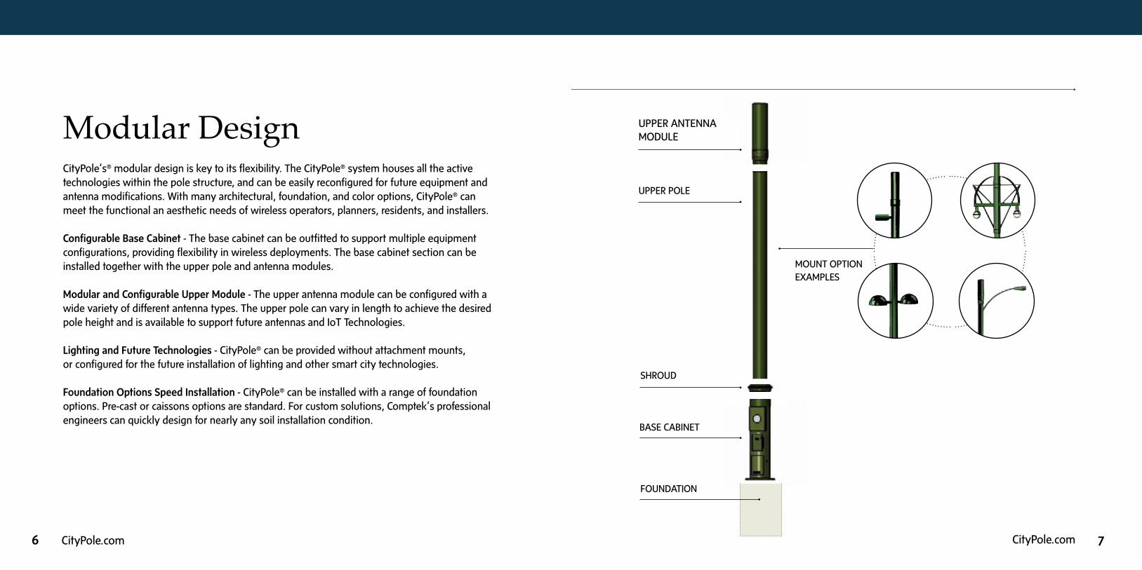
Modular DesignThe CityPole™ was designed for ease of Installation and the future in mind.
TOWER COMPONENTS
The two (2) component design allows the lower equipment cabinet to be outfitted and optionally
installed by the contractor in the right of way in advance of the upper more slender pole section
that mounts the antenna equipment.
SINGLE AND MULTIPLE CARRIER ANTENNAS
Single carrier and multi carrier solutions can be customized using the wireless operators equipment
requirements.
STREETSCAPE AESTHETICS
Shroud designs are standardized and can be uniquely designed for the streetscape environment. All
shrouds are impact resistance. Pole coatings are available in any color and are impact and UV resistant.
LIGHTING AND FUTURE NEW TECHNOLOGIES
The pole structure is designed for LED lighting on cantilever arms, top mounted or side mounted.
Provisions can be offered for security sensors and new technologies.
FOUNDATIONS
Precast and cast-in-situ foundation options exist for each pole type. Field design modifications can
be expedited by in-house professional engineers to accommodate unforeseen substructure conditions.
UPPER POLE
LOWER CABINET
FOUNDATION
SHROUD
ANTENNA
MOUNT OPTIONEXAMPLES
UPPER ANTENNA MODULE
CityPole’s® modular design is key to its flexibility. The CityPole® system houses all the active technologies within the pole structure, and can be easily reconfigured for future equipment and antenna modifications. With many architectural, foundation, and color options, CityPole® can meet the functional an aesthetic needs of wireless operators, planners, residents, and installers.
Configurable Base Cabinet - The base cabinet can be outfitted to support multiple equipment configurations, providing flexibility in wireless deployments. The base cabinet section can be installed together with the upper pole and antenna modules.
Modular and Configurable Upper Module - The upper antenna module can be configured with a wide variety of different antenna types. The upper pole can vary in length to achieve the desired pole height and is available to support future antennas and IoT Technologies.
Lighting and Future Technologies - CityPole® can be provided without attachment mounts, or configured for the future installation of lighting and other smart city technologies.
Foundation Options Speed Installation - CityPole® can be installed with a range of foundation options. Pre-cast or caissons options are standard. For custom solutions, Comptek’s professional engineers can quickly design for nearly any soil installation condition.
BASE CABINET
Modular Design

8 CityPole.com CityPole.com 9
Engineering
4 SmartCityPole.com
EngineeringEach CityPole™ design is engineered to satisfy national and local building code requirements.
An optimized use of internal space is achieved through three dimensional CAD modeling of all
internal components, structural supports and access door openings. Structural FEA modeling
is performed to optimize structural materials and assure a safe design in service. Bolted
connections are accessible and concealed from view and the environmental elements. Single
tenant and multi-tenant designs can be provided as required.
Finite element analysis.(Deflection is exaggerated.)
Integrated wireless equipment in base cabinet.
CityPole_brochure_FNL NEW.indd 4 5/18/17 2:54 PM
The CityPole® is engineered to the demanding standards of the
telecommunications industry. With its integrated base cabinet, wide
doors, and passive/active ventilation system, the CityPole™ satisfies
national and local building codes. Available material and space
is optimized by modeling all components in three dimensions.
The resulting computer model is analyzed for structural performance
using finite element methods (FEM). This engineering technique
assures efficient use of available space and materials while also
assuring a safe design.
In addition to modeling structural performance, the smart pole’s
thermal performance is also evaluated. As radios and other electronic
components compete for space, the smart pole’s ability to manage
heat generated by the radios, sensors, and other electronic devices
becomes important. Comptek engineers assure the heat generated
is properly managed by thermally modeling both the conductive
and convective heat flow, along with computational fluid dynamic
(CFD) modeling of the air moving through the cabinet. The technique,
when coupled with testing at national labs, assures internal environment remains consistent with the demands
of the installed electronics, regardless of external conditions.
The CityPole® is available in single or multi-tenant designs. Full scale Inter-Mod and PIM surveys are available
regardless of antenna or radio configuration. Bolted connections are readily accessiblie, yet easily hidden from
view, thus improving the aesthetics of the small cell installation contained within the CityPole®. The CityPole®
is engineered with the best technology available, assuring a clean installation while assuring an agile, high
performance equipment environment for the future.
Equipment surface temperature Thermal flow trajectories
10 CityPole.com CityPole.com 11
Fabrication and FinishThe CityPole® is made from durable, high quality materials and powder coated with finishes suitable for a 50 year life. Depending on options chosen, the CityPole® is made from structural steel, stainless steel, aerospace aluminum, or fiber-reinforced plastics (FRP). Corrosion protection is provided by powder coating, galvanizing, or the combination of both. Each pole is manufactured directly using Comptek’s engineering data files, assuring control of each design and an effective change management process. We are committed to using state-of-the-art fabrication technology and equipment to guarantee that fit and finishes are of high quality. Each section is individually labeled for ease of installation. All coating are UV rated and impact resistant, providing coating and color longevity.
The most noticeable feature is the selection of high quality, durable materials. Every CityPole® is protected internally and externally per our customers specifications. Common coatings include zinc undercoats or galvanizing with powder coating. Our coatings reliably resist UV, salt spray and extreme temperature ranges. The result is a highly durable and resistant product capable of resisting the outdoor environment under adverse conditions.
Fabrication and assembly performed internally and through Comptek’s certified network of nationwide specialty suppliers.
Comptek uses two main categories of powder coating: thermosets and thermoplastics. Thermosets are used for all exterior applications, and thermoplastics are used in interior applications when additional protection beyond galvanize is needed. Comptek specifies appropriate coatings for the installation environment, using polyester, polyurethane, polyester- epoxy hybrids, fusion-bonded epoxy, epoxy, and acrylics as necessary.
12 CityPole.com CityPole.com 13
8 SmartCityPole.com
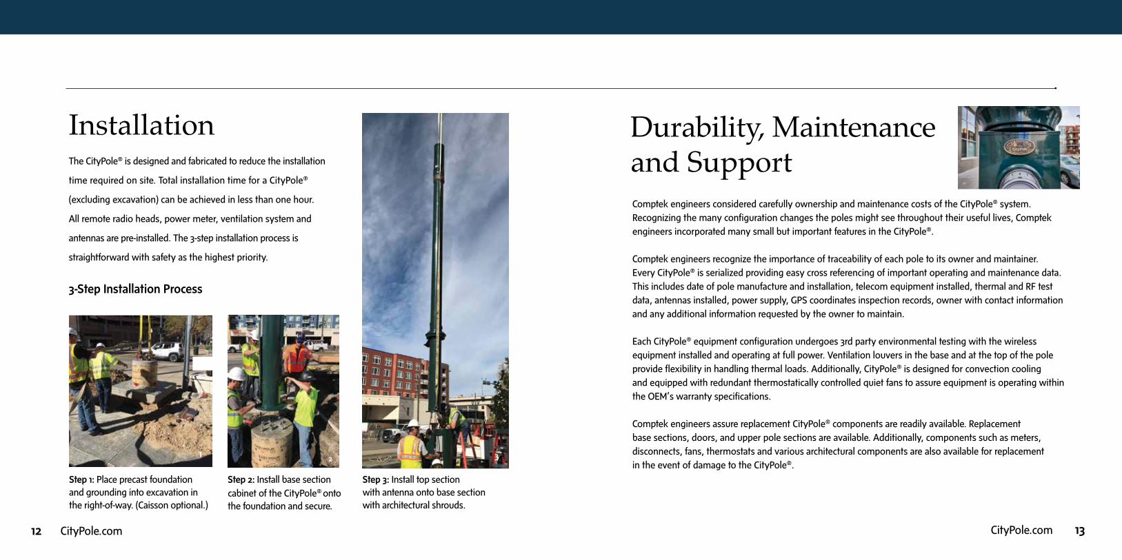
1 Place precast foundation and grounding into excavation in the right of way. 2 Install base section cabinet of the CityPole™ onto the foundation and secure.
3 Install top section with antenna onto base
section with architectural shrouds.
3-Step Insta l lat ion Process
CITY OF DENVER
The CityPole™ is designed and fabricated to reduce the
installation time required on site. Total installation time for
a CityPole™ excluding excavation, can be achieved in less
than one hour. All remote radio heads, power meter and
a ventilation system are pre-installed. The 3-step installation
process is straightforward with safety as the highest priority.
Installation
1
2
CityPole_brochure_FNL NEW.indd 8 5/18/17 2:54 PM
The CityPole® is designed and fabricated to reduce the installation
time required on site. Total installation time for a CityPole®
(excluding excavation) can be achieved in less than one hour.
All remote radio heads, power meter, ventilation system and
antennas are pre-installed. The 3-step installation process is
straightforward with safety as the highest priority.
3-Step Installation Process
Installation
Step 2: Install base section cabinet of the CityPole® onto the foundation and secure.
Step 3: Install top section with antenna onto base section with architectural shrouds.
8 SmartCityPole.com
1 Place precast foundation and grounding into excavation in the right of way. 2 Install base section cabinet of the CityPole™ onto the foundation and secure.
3 Install top section with antenna onto base
section with architectural shrouds.
3-Step Insta l lat ion Process
CITY OF DENVER
The CityPole™ is designed and fabricated to reduce the
installation time required on site. Total installation time for
a CityPole™ excluding excavation, can be achieved in less
than one hour. All remote radio heads, power meter and
a ventilation system are pre-installed. The 3-step installation
process is straightforward with safety as the highest priority.
Installation
1
2
CityPole_brochure_FNL NEW.indd 8 5/18/17 2:54 PM
SmartCityPole.com 9
34 53
Step 1: Place precast foundation and grounding into excavation in the right-of-way. (Caisson optional.)
Comptek engineers considered carefully ownership and maintenance costs of the CityPole® system. Recognizing the many configuration changes the poles might see throughout their useful lives, Comptek engineers incorporated many small but important features in the CityPole®.
Comptek engineers recognize the importance of traceability of each pole to its owner and maintainer.Every CityPole® is serialized providing easy cross referencing of important operating and maintenance data. This includes date of pole manufacture and installation, telecom equipment installed, thermal and RF test data, antennas installed, power supply, GPS coordinates inspection records, owner with contact information and any additional information requested by the owner to maintain.
Each CityPole® equipment configuration undergoes 3rd party environmental testing with the wireless equipment installed and operating at full power. Ventilation louvers in the base and at the top of the pole provide flexibility in handling thermal loads. Additionally, CityPole® is designed for convection cooling and equipped with redundant thermostatically controlled quiet fans to assure equipment is operating within the OEM’s warranty specifications.
Comptek engineers assure replacement CityPole® components are readily available. Replacement base sections, doors, and upper pole sections are available. Additionally, components such as meters, disconnects, fans, thermostats and various architectural components are also available for replacement in the event of damage to the CityPole®.
Durability, Maintenance and Support
14 CityPole.com CityPole.com 15
THE COMPTEKSPECIFICATIONSYSTEM
The Comptek Specification SystemThe CityPole® is customization. Each pole, in each location, can be uniquely configured to support different combinations of technology and architectural elements. This allows a CityPole® deployment to blend into the look and feel of any community.
When configuring a CityPole®, the selection process must consider regulatory, technical and aesthetic factors. The successful deployment of a CityPole® must comply with federal and local jurisdictional requirements, public safety, wireless carrier near term and longer term objectives and community acceptance. Common factors and decisions taken into account during the design process include:
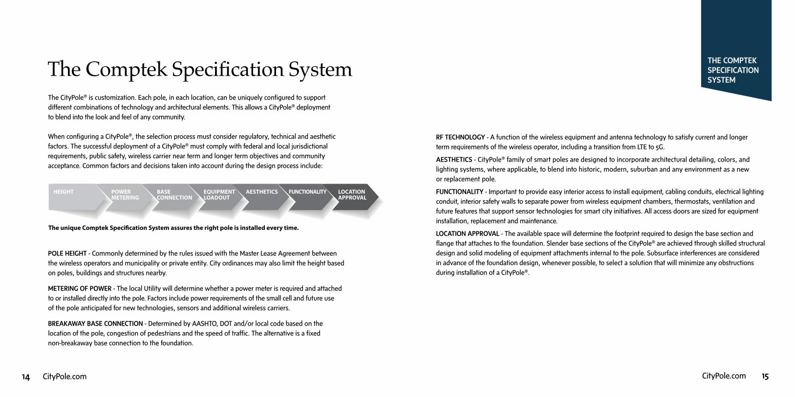
POLE HEIGHT - Commonly determined by the rules issued with the Master Lease Agreement between the wireless operators and municipality or private entity. City ordinances may also limit the height based on poles, buildings and structures nearby.
METERING OF POWER - The local Utility will determine whether a power meter is required and attached to or installed directly into the pole. Factors include power requirements of the small cell and future use of the pole anticipated for new technologies, sensors and additional wireless carriers.
BREAKAWAY BASE CONNECTION - Determined by AASHTO, DOT and/or local code based on the location of the pole, congestion of pedestrians and the speed of traffic. The alternative is a fixed non-breakaway base connection to the foundation.
RF TECHNOLOGY - A function of the wireless equipment and antenna technology to satisfy current and longer term requirements of the wireless operator, including a transition from LTE to 5G.
AESTHETICS - CityPole® family of smart poles are designed to incorporate architectural detailing, colors, and lighting systems, where applicable, to blend into historic, modern, suburban and any environment as a new or replacement pole.
FUNCTIONALITY - Important to provide easy interior access to install equipment, cabling conduits, electrical lighting conduit, interior safety walls to separate power from wireless equipment chambers, thermostats, ventilation and future features that support sensor technologies for smart city initiatives. All access doors are sized for equipment installation, replacement and maintenance.
LOCATION APPROVAL - The available space will determine the footprint required to design the base section and flange that attaches to the foundation. Slender base sections of the CityPole® are achieved through skilled structural design and solid modeling of equipment attachments internal to the pole. Subsurface interferences are considered in advance of the foundation design, whenever possible, to select a solution that will minimize any obstructions during installation of a CityPole®.
HEIGHT POWERMETERING
BASE CONNECTION
EQUIPMENTLOADOUT
AESTHETICS FUNCTIONALITY LOCATIONAPPROVAL
The unique Comptek Specification System assures the right pole is installed every time.
16 CityPole.com CityPole.com 17
The Selection ProcessThe Selection Process for a CityPole® can be simplified with a primary set of information and parameters. Once defined, the geometry of the CityPole® can readily be established with provisions identified for future uses of the structure. The process below is intended to define the information necessary to advance a solution forward to review together. Once received, our team will provide a recommended CityPole® and options to consider. Though our deployment solutions are customized, the CityPole® is comprised of
standard components to reduce costs and expedite fabrication. This process involves knowledge of the internal equipment and antennas, use of shapes, colors, and custom shrouds that blend with the surroundings.
STEP 1 - Select the height of the pole, determined by the antenna rad center(s), use of pole and any municipal height requirements.
STEP 2 - Identify from wireless operator the wireless equipment and antenna options to achieve the performance required of the small cell node transmission. This information allows us to determine the base cabinet options available for the technology configuration, including internal cabinet space required for thermal management, cabling for power supply, backhaul fiber connections (when applicable), duct for antenna and future IoT sensors.
STEP 3 - Establish if the CityPole® is metered of unmetered by the utility company or wireless operator. When metering is required, our team can assist in selection of meter options available for integration into the pole.
THE SELECTIONPROCESS
STEP 4 - Select an upper pole and antenna module. The upper pole height is typically selected with consideration of the antenna height and the diameter to provide for an aesthetic transition between the pole and antenna canister or panel configuration, and consideration of surrounding pole architecture. Our design team has developed solutions to maintain a slender form factor when panel antennas are specified by the RF engineer.
STEP 5 - Where lighting is required today or at a future date, identify the appearance being sought and our design team will provide solutions. Where existing lighting fixtures are known, we will design the CityPole® using a close match or identical fixture solutions.
STEP 6 - A foundation type is recommended by our engineers based on the location of the pole and whether right-of-way subsurface interferences exist.
STEP 7 - With the structure defined, detailing of the CityPole® can occur to select the cross section shape and color. Architectural shrouds are used at the interface of the base cabinet and upper pole, and transition of the upper pole to antenna module. A base shroud may also be used with consideration for the access opening locations.
Our selection process is proven to result in a highly functional smart pole that is durable and adaptable to future uses as technology changes require.
Our team is experienced
in closely collaborating
with all stakeholders
throughout the project
lifecycle, from achieving
the right solution to
facilitating installation
and future upgrades.
18 CityPole.com CityPole.com 19
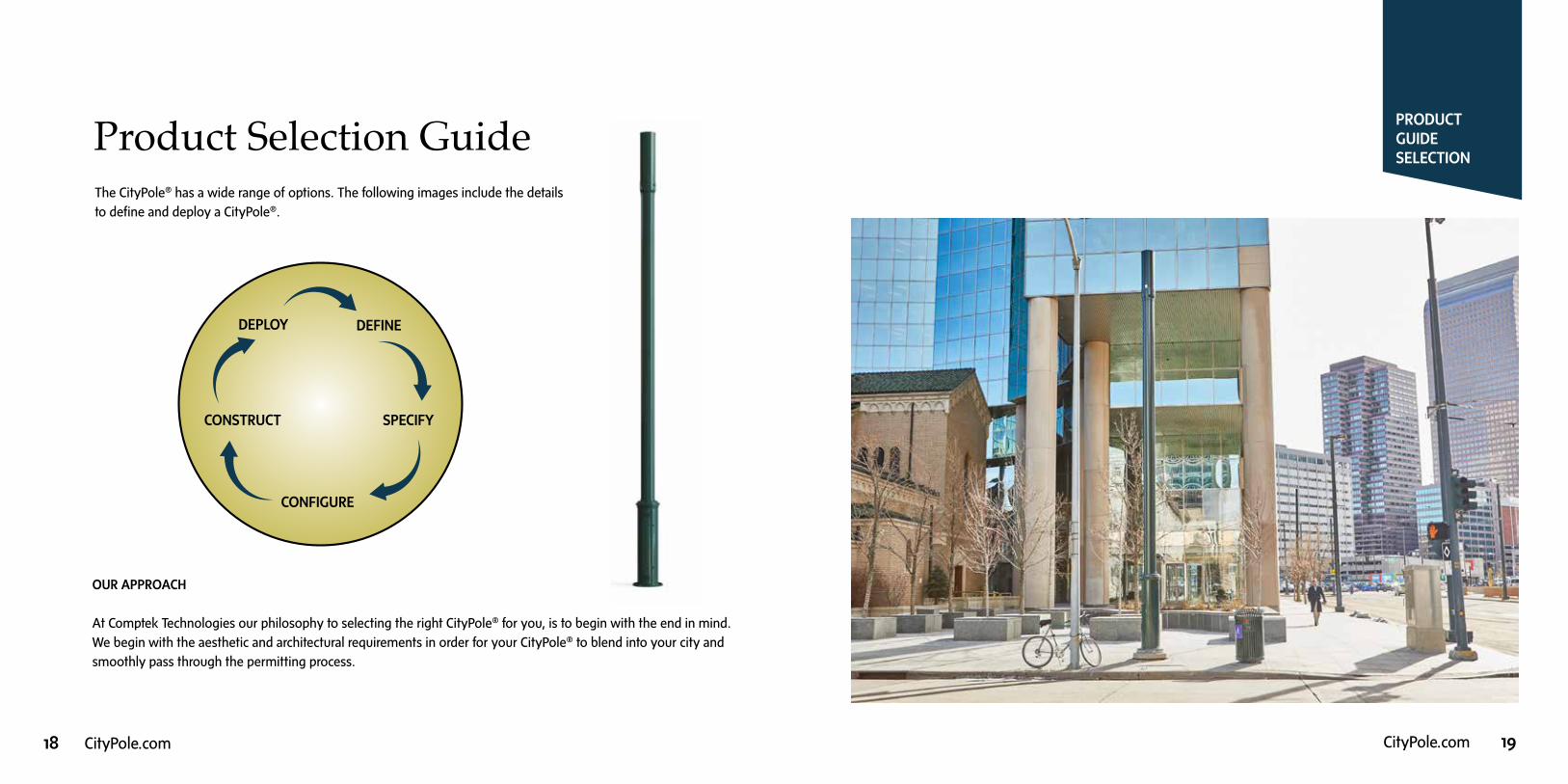
Product Selection GuideThe CityPole® has a wide range of options. The following images include the details to define and deploy a CityPole®.
PRODUCT GUIDESELECTION
DEPLOY DEFINE
CONSTRUCT SPECIFY
CONFIGURE
OUR APPROACH
At Comptek Technologies our philosophy to selecting the right CityPole® for you, is to begin with the end in mind. We begin with the aesthetic and architectural requirements in order for your CityPole® to blend into your city and smoothly pass through the permitting process.
20 CityPole.com CityPole.com 21
ARCHITECTURALANDAESTHETICSELECTION
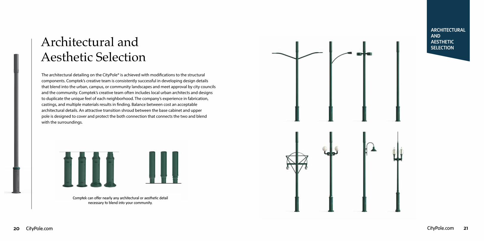
Architectural and Aesthetic SelectionThe architectural detailing on the CityPole® is achieved with modifications to the structural components. Comptek’s creative team is consistently successful in developing design details that blend into the urban, campus, or community landscapes and meet approval by city councils and the community. Comptek’s creative team often includes local urban architects and designs to duplicate the unique feel of each neighborhood. The company’s experience in fabrication, castings, and multiple materials results in finding. Balance between cost an acceptable architectural details. An attractive transition shroud between the base cabinet and upper pole is designed to cover and protect the both connection that connects the two and blend with the surroundings.
Comptek can offer nearly any architectural or aesthetic detail necessary to blend into your community.
22 CityPole.com CityPole.com 23
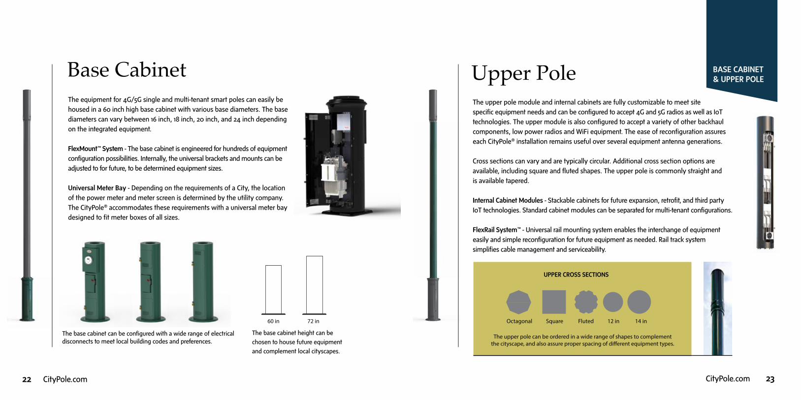
Base Cabinet The equipment for 4G/5G single and multi-tenant smart poles can easily be housed in a 60 inch high base cabinet with various base diameters. The base diameters can vary between 16 inch, 18 inch, 20 inch, and 24 inch depending on the integrated equipment.
FlexMount™ System - The base cabinet is engineered for hundreds of equipment configuration possibilities. Internally, the universal brackets and mounts can be adjusted to for future, to be determined equipment sizes.
Universal Meter Bay - Depending on the requirements of a City, the location of the power meter and meter screen is determined by the utility company. The CityPole® accommodates these requirements with a universal meter bay designed to fit meter boxes of all sizes.
BASE CABINET & UPPER POLE
The base cabinet can be configured with a wide range of electrical disconnects to meet local building codes and preferences.
The base cabinet height can be
chosen to house future equipment
and complement local cityscapes.
60 in 72 in
Upper PoleThe upper pole module and internal cabinets are fully customizable to meet site specific equipment needs and can be configured to accept 4G and 5G radios as well as IoT technologies. The upper module is also configured to accept a variety of other backhaul components, low power radios and WiFi equipment. The ease of reconfiguration assures each CityPole® installation remains useful over several equipment antenna generations.
Cross sections can vary and are typically circular. Additional cross section options are available, including square and fluted shapes. The upper pole is commonly straight and is available tapered.
Internal Cabinet Modules - Stackable cabinets for future expansion, retrofit, and third party IoT technologies. Standard cabinet modules can be separated for multi-tenant configurations.
FlexRail System™ - Universal rail mounting system enables the interchange of equipment easily and simple reconfiguration for future equipment as needed. Rail track system simplifies cable management and serviceability.
UPPER CROSS SECTIONS
Square Fluted 12 in 14 in
The upper pole can be ordered in a wide range of shapes to complement the cityscape, and also assure proper spacing of different equipment types.
Octagonal

24 CityPole.com CityPole.com 25
4G/5GSMALL CELL TECHNOLOGIESUpper Pole with
4G/5G Technologies 5G TechnologiesThe CityPole® team is experienced in deploying 5G radios and antennas having developed custom RF transparent antenna shrouds to accommodate multiple small cell radios.
Antenna shrouds can accommodate a tri-sector AIR (antenna integrated radio) array with adjustable brackets or mounted with the CityPole® vertical stacking loadout of the AIR units to create a slim shroud profile with easy azimuth adjustment.
The 4G/5G and 5G antenna shrouds are fully customizable to meet site specific equipment needs and can be configured to accept 1, 2, or 3 antenna or AIR arrays. The wide range of RF transparent materials ensure maximum signal coverage with reduced interference.
In addition to the fully integrated CityPole® solution, a decorative 5G concealment antenna and radio shroud is available to easily upgrade existing pole infrastructure with 5G technology.
The CityPole® 5G Concealment Pole Top is a mounting andconcealment solution for a wide range of existing or new poles inthe right-of-way. Passive and active thermal cooling availabledepending on the local environment. 5G Pole Top Concealmentsolutions can be easily be integrated with 4G technology and colormatched RF Transparent shroud.
26 CityPole.com CityPole.com 27
ENVIRONMENTALAND SERVICES CONTROL
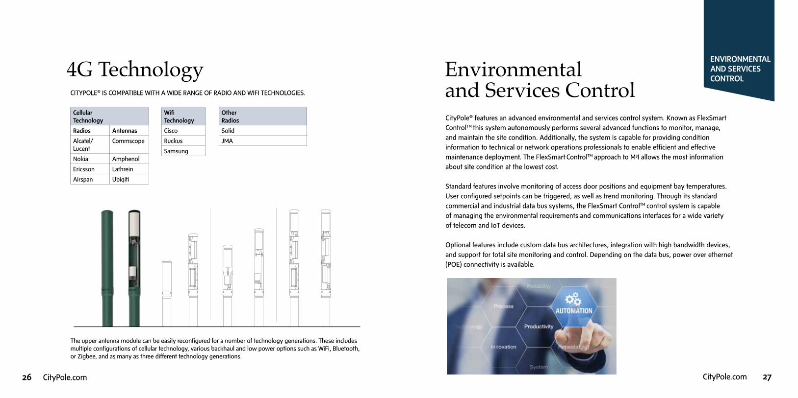
Environmental and Services ControlCityPole® features an advanced environmental and services control system. Known as FlexSmart
ControlTM this system autonomously performs several advanced functions to monitor, manage, and maintain the site condition. Additionally, the system is capable for providing condition information to technical or network operations professionals to enable efficient and effective maintenance deployment. The FlexSmart ControlTM approach to M3I allows the most information about site condition at the lowest cost.
Standard features involve monitoring of access door positions and equipment bay temperatures. User configured setpoints can be triggered, as well as trend monitoring. Through its standard commercial and industrial data bus systems, the FlexSmart ControlTM control system is capable of managing the environmental requirements and communications interfaces for a wide variety of telecom and IoT devices.
Optional features include custom data bus architectures, integration with high bandwidth devices, and support for total site monitoring and control. Depending on the data bus, power over ethernet (POE) connectivity is available.
STANDARD 360 DEGREE OMNI 360 DEGREE OMNI WITH
LOW POWERED RADIODUAL PANEL INTEGRATED
WIRELESS BACKHAUL
DUAL PANEL WITH 360 DEGREE OMNI (2 TECHNOLOGIES)
DUAL 180 DEGREE OMNIS WITH 360 OMNI(2 TECHNOLOGIES)
SINGLE TECHNOLOGY ANTENNA CONFIGURATIONS SINGLE TECHNOLOGY
ANTENNA WITH AUXILERY EQUIPMENT BAY
2 & 3 TECHNOLOGY ANTENNA CONFIGURATIONS
The upper antenna module can be easily reconfigured for a number of technology generations. These includes multiple configurations of cellular technology, various backhaul and low power options such as WiFi, Bluetooth, or Zigbee, and as many as three different technology generations.
CITYPOLE® IS COMPATIBLE WITH A WIDE RANGE OF RADIO AND WIFI TECHNOLOGIES.
Cellular Technology
Radios Antennas
Alcatel/ Lucent
Commscope
Nokia Amphenol
Ericsson Lathrein
Airspan Ubiqiti
Wifi Technology
Cisco
Ruckus
Samsung
OtherRadios
Solid
JMA
4G Technology

28 CityPole.com CityPole.com 29
LIGHTING ACCESSORIES
Lighting Accessories Lights are a vital component of all city environments, and cannot be overlooked. Lighting is vital for night illumination, but is also important for the city’s identity. Residents need to feel a sense of security and social presence and visitor and business people can be influenced by creating an inviting environment.
CityPole’s® can be ordered with a wide variety of lighting options. These include wireless controlled smart LED lighting for first responders, and energy conservation. Lights can be mounted with simple plates or offset arms to maximize illumination and the beauty of your cityscape.
More than 5,000 lighting attachments are available through the CityPole® network of distributors, including the nationally recognized Graybar Electric.
Leading brands include: Acuity-Lithonia Acuity Holophane Eaton-Cooper GE RoadwayHubbell LSI Clear World Sternberg
CityPole® offers nearly limitless options for lighting types and decorative mounts. Custom fabrication available.
2 SmartCityPole.com
CUSTOM DESIGNS USING STANDARDIZED MODULAR COMPONENTS
CityPole_brochure_FNL NEW.indd 25/18/17 2:54 PM
CityPole® offers nearly limitless options for lighting types and decorative mounts.

30 CityPole.com CityPole.com 31
Smart Cities Technology CityPole® easily enables the mounting and integration of sensor information into public safety and community access systems. By serving as an ‘Eco-system for Smart City Technologies’ the CityPole® plays an important role in integrating sensors and applications that knit the fabric of society closer together.
As Smart Cities around the country deploy millions of sensors and endpoints, the CityPole® will be an essential part of any deployment plan. With 50 year life and a fully modular design, the CityPole® can easily be configured, upgraded or changed throughout its life cycle as the city’s technology needs mature and change.
Whether your needs are related to Smart Energy, Smart Transportation, Smart Data or Smart Mobility, the CityPole® can be configured to meet those rapidly emerging and changing needs.
TECHNOLOGYACCESSORIES
• Smart Lighting Hub and Environmental Sensors
• 360 Video Surveillance
• Gunshot Detection System
• LED displays for parking information and safety alerts
• Wifi hub capabilities
• Charging integration for e-vehicles and smart devices
• High Efficiency SMART LED lighting
• RFID technology
• Customizable Sensor Mount System
ENVIRONMENTAL MONITORING
TRANSPORTATION AND TRAFFIC MANAGEMENT
PUBLIC SAFETY AND SECURITY
32 CityPole.com CityPole.com 33
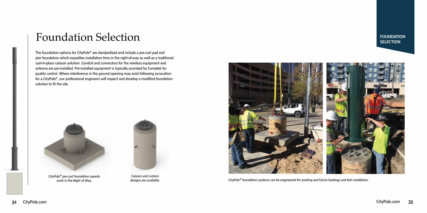
Foundation SelectionThe foundation options for CityPole® are standardized and include a pre-cast pad and pier foundation which expedites installation time in the right-of-way as well as a traditional cast-in-place caisson solution. Conduit and connectors for the wireless equipment and antenna are pre-installed. Pre-installed equipment is typically provided by Comptek for quality control. Where interference in the ground opening may exist following excavation for a CityPole®, our professional engineers will inspect and develop a modified foundation solution to fit the site.
CityPole® pre-cast foundation speeds work in the Right of Way.
Caisson and custom designs are available.
FOUNDATIONSELECTION
8 SmartCityPole.com
1 Place precast foundation and grounding into excavation in the right of way. 2 Install base section cabinet of the CityPole™ onto the foundation and secure.
3 Install top section with antenna onto base
section with architectural shrouds.
3-Step Insta l lat ion Process
CITY OF DENVER
The CityPole™ is designed and fabricated to reduce the
installation time required on site. Total installation time for
a CityPole™ excluding excavation, can be achieved in less
than one hour. All remote radio heads, power meter and
a ventilation system are pre-installed. The 3-step installation
process is straightforward with safety as the highest priority.
Installation
1
2
CityPole_brochure_FNL NEW.indd 8 5/18/17 2:54 PM
CityPole® foundation systems can be engineered for existing and future loadings and fast installation.

34 CityPole.com CityPole.com 35
PRODUCTSELECTIONMATRIX
Product Selection Matrix
Standard CityPole® System Offering Custom Options
Overall Pole Height 25’, 30’, 35’, and 40’ Above Ground Level (AGL) Available
Color Choices 9 Color Choices are Standard (Custom colors are available.)
Base Cabinet Technology Types 1, 2, or 3 Different Technologies can be Accommodated
Dimension Ground Diameter: 18”, 20”, 24” | Height: 60”, Optional 72”
Flexible Mount System FlexMountTM system to reconfigure internals for future equipment sizes.
Electrical Options No Disconnect, Disconnect Only, or Meter and Disconnect.
Universal Meter Bay Accommodates power meter and meter screen requirements as deter-mined by local utility provider; fits meter boxes of all sizes.
Upper Pole Antenna Module
Rad Center Location Variable and Based on Pole Height and Other Options
Technology Types 1, 2, or 3 Different Technologies can be Accommodated
Auxiliary Bay Options Low Power RF, Backhaul, and Wifi Options can be Accommodated. Multiple and reconfigurable 123/4 inch modules with RlexRailTM universal equipment track system optional.
Antenna Mount and Shroud Options
Separate and Secure Bays with RF Transparent Materials to accomodate 4G/5G Equipment. Omni and Panel Types available.
Accessory Selection Lighting Pole can be ordered without lighting or with 1,2,3, or 4 lights.
Light Mounts Standard Plate or Offset Arms depending on light selection
Lighting Shoebox, Cobrahead, Cylindrical, Dome and Acorn
Other Technology Gun Shot Sensors, Video, Weather, Traffic Mgmt
Lower Shroud Details Multiple Options are Available
Base Plate Details Multiple Options are Available
Foundation Options Pre-cast, or Cast-in-Place
Environmental Control
Thermal Management All Equipment and Antenna Bays Monitored for Temperature. Passive and Forced Air Standard; Heat Pipe and Thermoelectrical Optional
Security External and Internal Locking Features. CityPole® FlexSmartTM
Control and Connectivity Optional.
Monitoring and Control Industrial Controller with 24 Digital and 12 Analog Inputs with FlexSmartTM
The matrix summarizes the many different combinations of equipment available for the CityPole® product. The modular system can be easily customized to meet site-specific needs.
CITYPOLE® STANDARD RAL COLOR OPTIONS
CUSTOM COLORS AND NATURAL FINISHES ARE AVAILABLE UPON REQUEST
Green/ Black6012
Brown
8019
GalvanizeBrown9007
Signal/Traffic Black
9004
RubyRed
3003
SignalWhite9003
FawnBrown8007
Galvanized
Custom Color
Antique Silver
Metallic1424
GreyHybrid
1425
Sandy Concrete
1426
Pacific Coast1428
PebbleBeach1427

36 CityPole.com CityPole.com 37
PRODUCTEXAMPLES
Product ExamplesThe CityPole® system is tailor made for easy installation and use in a wide range
of environments. The following pages include several examples of CityPole® solutions
in many different environments. The opportunities for applications are limited only
by the inspiration and creativity of the deployment team.
Upper pole photo. Architectural shroud between base cabinet and upper pole.
CityPole® photo in Denver, Colorado.

38 CityPole.com CityPole.com 39
Urban LandscapesDesign solutions for the CityPole® in the urban environment often require special considerations for architectural lighting that satisfies the streetscape and existing lighting structures. This solution is particularly suitable for the replacement of existing light poles with a CityPole® that replicates those removed. Optional sensor technologies can be installed.
URBAN CENTER COLLEGE CAMPUS
Unique CampusApplicationsStandardized equipment in this unique modular pole design allows for tailored lighting configurations and university colors can match the aesthetics found on campus. The pole can incorporate metered power options to satisfy local utility requirements.
40 CityPole.com CityPole.com 41
SHOPPING MALL
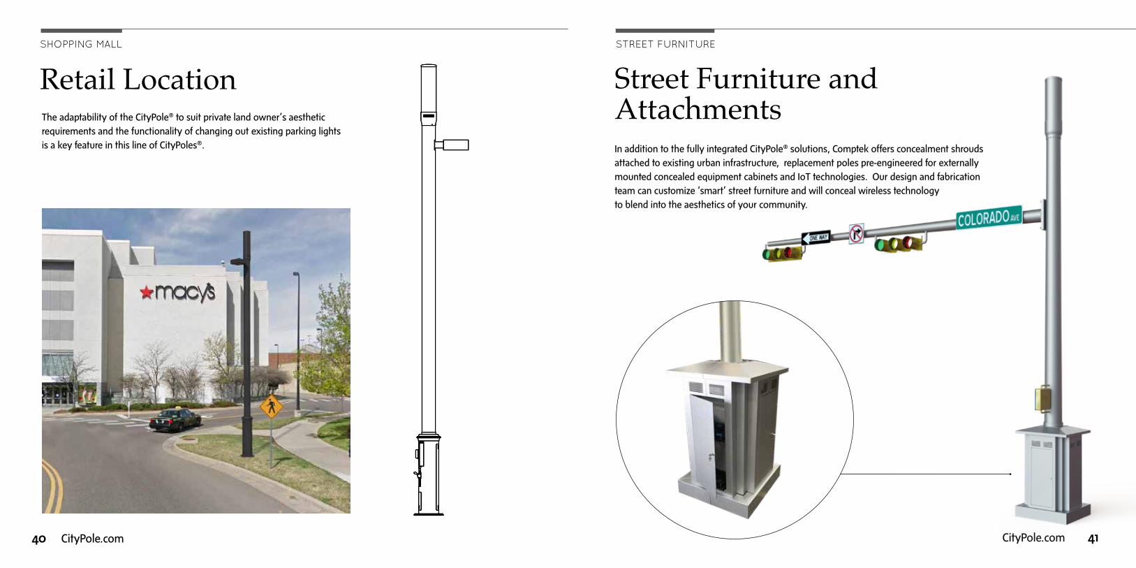
The adaptability of the CityPole® to suit private land owner’s aesthetic requirements and the functionality of changing out existing parking lights is a key feature in this line of CityPoles®.
Retail Location
Street Furniture and Attachments In addition to the fully integrated CityPole® solutions, Comptek offers concealment shrouds attached to existing urban infrastructure, replacement poles pre-engineered for externally mounted concealed equipment cabinets and IoT technologies. Our design and fabrication team can customize ‘smart’ street furniture and will conceal wireless technology to blend into the aesthetics of your community.
STREET FURNITURE

42 CityPole.com CityPole.com 43
Comptek was established in New York City in 1998 as a product development company and
fabricator of engineered composite, alloy and metal infrastructure products for the wireless
and energy markets. The company is a member of the Aero Wireless Group of Boulder, CO
that provides small cell and macro cell collocation engineering services, smart poles (CityPole®),
antenna shrouds, wireless street furniture, construction management and consulting to
communities and wireless operators seeking to expedite their wireless deployment programs.
Comptek has developed a full product line of small cell infrastructure and concealment structures
to support small cell deployments. The CityPole® (www.citypole.com) is being deployed across
multiple states in the public right-of-way, onto private landlord sites, university campuses and
private developments. The City of Denver adopted the CityPole® in early 2016 as its preferred
standard smart pole, following numerous review board approvals and city council. Comptek
has deployed the CityPole® throughout downtown Denver and will provide a minimum of 400
CityPole® in the right-of-way between 2016 and 2018. The CityPole® has been installed with
4G and 5G technologies for single carriers, and will be deployed with a multi-carrier solution
in 2017-2018.
The Aero Wireless Group has worked extensively throughout the U.S. for the major wireless carriers,
neutral host providers, municipalities and utility companies, completing over 4000 turnkey projects.
Our 15 year wireless infrastructure background working in macro cell and small cell technologies provides
our company a unique understanding of the importance of experienced engineering, quality fabrication
and CityPole® design solutions that minimize construction time in the right-of-way. Outside the U.S.,
the Aero Wireless group has performed projects in Hawaii, Alaska, Puerto Rico, Portugal, Bermuda, and
Southeast Asia, working for the United Nations and governments.
The company takes a leadership role in the wireless industry, actively serving on WIA’s HetNet Innovative
Technology Council, as members and active participants in WIA, CTIA, HetNet Forum, Smart Cities Council,
NATOA, UTC, and national standards committees including TIA. CityPoleTM has proven to be an excellent
choice for municipalities, university campuses, and other locations where wireless densification is required.
Innovative Wireless Infrastructure Solutions
TAKING A LEADERSHIP ROLE IN THE WIRELESS INDUSTRY Aero Wireless Group
Aero Wireless Group

5555 Central Avenue, Suite 100
Boulder, Colorado 80301
Email: [email protected]
Phone: 303.531.5758 | Fax: 303.531.5595
CityPole.com
Aero Wireless Group
Aero Wireless Group