smart parking management system based on rfid
TRANSCRIPT
Smart Parking Management System Based on
RFID
Weiwei Wang Beijing University of Posts and Telecommunications, Beijing, China
Email: [email protected]
Pengfei Ma Duke University, Durham, NC, America
Email: [email protected]
Abstract—This paper presents the design of a smart
parking managemnet system which consists of non-stop
automatic gate guard payment system and parking spot
detection system. We first briefly introduce RFID technique
and discuss its operating principles. Then we propose a
design for controlling and managing parking system using
RFID technique which is able to automatically calculate the
parking fee of vehicles and show the number of unoccupied
parking space in the screen at the entrance. Finally, we
simulated the anti-interference ability of Manchester coding
and decoding in this RFID system, the radio-frequency
interference circuit of RF tag and the transmission and
receiving module of the RF reader using the simulation
software Simulink.
Index Terms—RFID, parking management system, simulink
I INTRODUCTION
With the rapid development of society, the number of
various vehicles significantly increases. In some cities,
the existing parking management system cannot
efficiently operate thus raises congestion problem.
Moreover, drivers cannot be notified about the number of
parking spaces in the sparking lot before their entrance,
which exacerbate the congestion problem. To circumvent
this problem, we propose a smart parking management
system, which is composed of two aspects: automatic
collection of parking fee and detection of the number of
available parking spaces [1]. To enable the system to
efficiently operate, we employs radio frequency
identification technique (RFID).
As a wireless data transmission technique, RFID is
used in smart parking management system with multiple
advantages[2]: (1) at least 9 meters identification distance
and capability to identify static and high-speed mobile
objects at a speed of 100 km/h; (2) the capability to
identify multiple radio-frequency cards with different
serial numbers; (3) no electromagnetic pollution; (4) high
security and privacy; (5) easy to install and maintain.
The remainder of this paper is organized as follows.
First, in section 2, we describe RFID technique and its
Manuscript received February 25, 2013; revised July 18, 2013
principles. Next, in section 3, we present the structure of
smart parking management system and the results of
simulation in section 5, and conclude in section 6.
II RFID
Radio-frequency identification achieves non-contact
and bidirectional communications between the reader and
a radio-frequency card through using radio-frequency
electromagnetic fields. A RFID system consists of four
components: electronic tag, reader, computer
communication network and antenna.
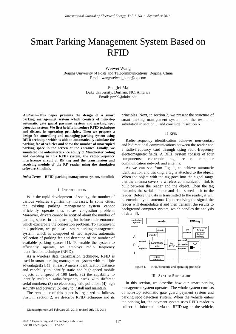
As we can see from Fig. 1, to achieve automatic
identification and tracking, a tag is attached to the object.
When the object with the tag goes into the signal range
that the antenna covers, a wireless communication link is
built between the reader and the object. Then the tag
transmits the serial number and data stored in it to the
reader. Before the data is transmitted to the reader, it will
be encoded by the antenna. Upon receiving the signal, the
reader will demodulate it and then transmit the results to
background computer system, which handles the analysis
of data [3].
Figure 1. RFID structure and operating principle
III SYSTEM STRUCTURE
In this section, we describe how our smart parking
management system operates. The whole system consists
of non-stop automatic gate guard payment system and
parking spot detection system. When the vehicle enters
the parking lot, the payment system uses RFID reader to
collect the information via the RFID tag on the vehicle,
117©2013 Engineering and Technology Publishingdoi: 10.12720/ijoee.1.3.117-122
International Journal of Electrical Energy, Vol. 1, No. 3, September 2013
then send the information to control computer, storing
vehicle information, entrance time and picture into the
database. At the time the vehicle exits, relative
information is obtained via RFID tag and the parking
time is calculated and stores the picture again. Parking
spot detection system: each parking spot requires a RFID
tag and an ultrasonic probe, which serves to detect the
availability of the parking spot and the tag is responsible
for sending the status of parking spot and its sequence
number to control computer through RF network. The
backend control computer communicate with RF tag by
RF reader and update the database when tag information
is received.
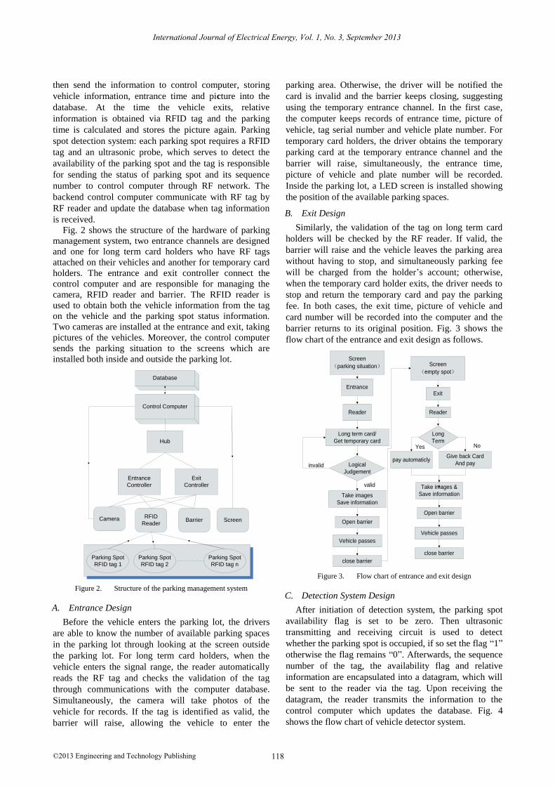
Fig. 2 shows the structure of the hardware of parking
management system, two entrance channels are designed
and one for long term card holders who have RF tags
attached on their vehicles and another for temporary card
holders. The entrance and exit controller connect the
control computer and are responsible for managing the
camera, RFID reader and barrier. The RFID reader is
used to obtain both the vehicle information from the tag
on the vehicle and the parking spot status information.
Two cameras are installed at the entrance and exit, taking
pictures of the vehicles. Moreover, the control computer
sends the parking situation to the screens which are
installed both inside and outside the parking lot.
Control Computer
Hub
Exit
Controller
Entrance
Controller
BarrierRFID
ReaderCamera Screen
Parking Spot
RFID tag 1
Parking Spot
RFID tag 2
Parking Spot
RFID tag n
Database
Figure 2. Structure of the parking management system
A. Entrance Design
Before the vehicle enters the parking lot, the drivers
are able to know the number of available parking spaces
in the parking lot through looking at the screen outside
the parking lot. For long term card holders, when the
vehicle enters the signal range, the reader automatically
reads the RF tag and checks the validation of the tag
through communications with the computer database.
Simultaneously, the camera will take photos of the
vehicle for records. If the tag is identified as valid, the
barrier will raise, allowing the vehicle to enter the
parking area. Otherwise, the driver will be notified the
card is invalid and the barrier keeps closing, suggesting
using the temporary entrance channel. In the first case,
the computer keeps records of entrance time, picture of
vehicle, tag serial number and vehicle plate number. For
temporary card holders, the driver obtains the temporary
parking card at the temporary entrance channel and the
barrier will raise, simultaneously, the entrance time,
picture of vehicle and plate number will be recorded.
Inside the parking lot, a LED screen is installed showing
the position of the available parking spaces.
B. Exit Design
Similarly, the validation of the tag on long term card
holders will be checked by the RF reader. If valid, the
barrier will raise and the vehicle leaves the parking area
without having to stop, and simultaneously parking fee
will be charged from the holder’s account; otherwise,
when the temporary card holder exits, the driver needs to
stop and return the temporary card and pay the parking
fee. In both cases, the exit time, picture of vehicle and
card number will be recorded into the computer and the
barrier returns to its original position. Fig. 3 shows the
flow chart of the entrance and exit design as follows.
Entrance
Reader
Logical
Judgement
Long term card/
Get temporary card
Take images
Save information
Open barrier
Vehicle passes
close barrier
valid
invalid
Reader
Long
Term
Take images &
Save information
Open barrier
Vehicle passes
close barrier
pay automaticly
Yes
Give back Card
And pay
No
Exit
Screen
(empty spot)
Screen
(parking situation)
Figure 3. Flow chart of entrance and exit design
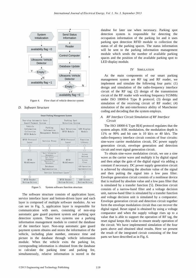
C. Detection System Design
After initiation of detection system, the parking spot
availability flag is set to be zero. Then ultrasonic
transmitting and receiving circuit is used to detect
whether the parking spot is occupied, if so set the flag “1”
otherwise the flag remains “0”. Afterwards, the sequence
number of the tag, the availability flag and relative
information are encapsulated into a datagram, which will
be sent to the reader via the tag. Upon receiving the
datagram, the reader transmits the information to the
control computer which updates the database. Fig. 4
shows the flow chart of vehicle detector system.
118©2013 Engineering and Technology Publishing
International Journal of Electrical Energy, Vol. 1, No. 3, September 2013
System
Initialization
availability flag→0
Ultrasonic Vehicle
Detector
Empty?
availability flag→1
Send Status
Information
Reader
Control Computer
Database Update
N
Y
Ultrasonic Vehicle
Detector
Empty? N
Yavailability flag→0
Figure 4. Flow chart of vehicle detector system
D. Software Structure
Smart Parking Management System
Non-stop Automatic Gate Guard Payment System
Parking Spot Detection System
Parking Information
Management Module
Service Interface Layer
Service Proxy
Database Implementation
Basic Information Management
Spot Status Management
Operation Log Management
Vehicle Information CollectionRFID Module
RFID Protocol Layer
Spot DetectionRFID Module
RFID Protocol Layer
LED DisplayModule
Function Library
RFIDMiddleware
RFIDMiddleware
LED Operation
Implementation
Screen Refresh
Screen Clear
RFID Reader Bottom-Driven
RFID Reader Bottom-Driven
LED Screen Bottom-Driven
Figure 5. System software function structure
The software structure consists of application layer,
service interface layer and bottom-driven layer and each
layer is composed of multiple software modules. As we
can see in Fig. 5, application layer is responsible for
communication with users, consisting of non-stop
automatic gate guard payment system and parking spot
detection system. These two systems use a parking
information management module to control the database
of the interface layer. Non-stop automatic gate guard
payment system obtains and stores the information of the
vehicle, including plate number, entrance time and
picture in the database through vehicle information
module. When the vehicle exits the parking lot,
corresponding information is obtained from the database
to calculate the parking time and parking fee,
simultaneously, relative information is stored in the
databse for later use when necessary. Parking spot
detection system is responsible for detecting the
occupation information of the parking lot and it uses
parking spot detection RFID module to collection the
status of all the parking spaces. The status information
will be sent to the parking information management
module which sends the number of available parking
spaces and the position of the available parking spot to
LED display module.
IV SIMULATION
As the main components of our smart parking
management system are RF tag and RF reader, we
implement and simulate the following four parts: (1)
design and simulation of the radio-frequency interface
circuit of the RF tag; (2) design of the transmission
circuit of the RF reader with working frequency 915MHz
under ISO 18000-6 Type B protocol; (3) design and
simulation of the receiving circuit of RF reader; (4)
simulation of the anti-interference ability of Manchester
coding and decoding that the system employs.
A. RF Interface Circuit Simulation of RF Interface
Circuit
The ISO 18000-6 Type B[4] protocol regulates that the
system adopts ASK modulation, the modulation depth is
11% or 99% and bit rate is 10 kb/s or 40 kb/s. The
radio-frequency interface circuit consists of four circuits:
sine-wave carrier modulation circuit, DC power supply
generation circuit, envelope generation and detection
circuit and reset signal generation circuit.
To obtain sine-wave modulation circuit, we use a sine
wave as the carrier wave and multiply it by digital signal
and then adapt the gain of the digital signal via adding a
constant if necessary. DC power supply generation circuit
is achieved by obtaining the absolute value of the signal
and then putting the signal into a low pass filter.
Envelope generation circuit consists of a nonlinear device
that is realized by absolute value and a low pass filter that
is simulated by a transfer function [5]. Detection circuit
consists of a narrow-band filter and a voltage decision
unit, narrow-band filter is simulated by a transfer function
and voltage decision unit is simulated by a comparator.
Envelope generation circuit and detection circuit together
form the envelope modulation circuit thus can recover the
digital signal. Reset signal is obtained by using a voltage
comparator and when the supply voltage rises up to a
value that is able to support the operation of RF tag, the
reset signal keeps this value to ensure steady operation of
the circuit. We have implemented simulation of the four
parts above and obtained ideal results. Here we present
the result of the integrated circuit consisting of the four
parts we have described as in Fig. 6.
119©2013 Engineering and Technology Publishing
International Journal of Electrical Energy, Vol. 1, No. 3, September 2013
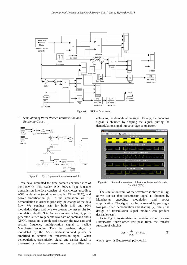
Figure 6. RF interface circuit
B. Simulation of RFID Reader Transmission and
Receiving Circuit
Figure 7. Type B protocol transmission module
We have simulated the time-domain characteristics of
the 915MHz RFID reader. ISO 18000-6 Type B reader
transmission interface consists of Manchester encoding,
ASK modulation (modulation depth 11% or 99%), and
power amplification [6]. In the simulation, we use
demodulation in order to precisely the change of the data
flow. We conduct tests for both 11% and 99%
modulation depth and here we present the test results for
modulation depth 99%. As we can see in Fig. 7, pulse
generator is used to generate raw data or command and a
XNOR operation is conducted between the raw data and
second frequency multiplication signal to realize
Manchester encoding. Then the baseband signal is
modulated by the ASK modulation and power is
amplified to achieve the transmission signal. When
demodulation, transmission signal and carrier signal is
processed by a down converter and low pass filter thus
achieving the demodulation signal. Finally, the encoding
signal is obtained by shaping the signal, putting the
demodulation signal into a voltage comparator.
Figure 8. Simulation waveform of the transmission module under Simulink (99%)
The simulation result of the waveform is shown in Fig.
8; we can see that transmission signal is obtained by
Manchester encoding, modulation and power
amplification. The signal can be recovered by passing a
low pass filter, demodulation and shaping [7]. Thus, the
design of transmission signal module can produce
desirable result.
As in Fig. 9, to simulate the receiving circuit, we use
Butterworth fourth-order low pass filter, the transfer
function of which is
)/()(
)( 0csS
SB
ASA
(1)
where )(SB is Butterworth polynomial.
120©2013 Engineering and Technology Publishing
International Journal of Electrical Energy, Vol. 1, No. 3, September 2013
432 613.2414.3613.21)( SSSSSB (2)
In simulation, we set Hzc 100 .
Figure 9. Receiving module
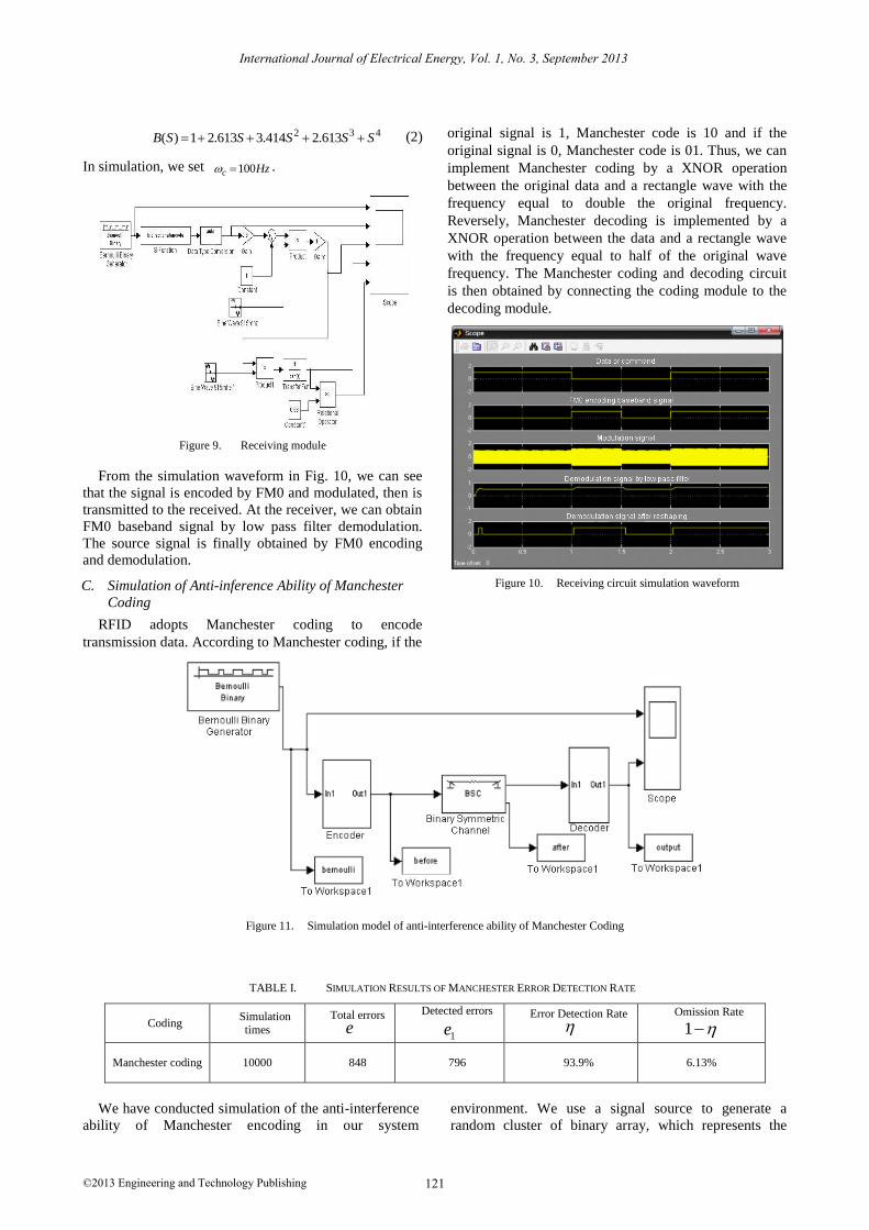
From the simulation waveform in Fig. 10, we can see
that the signal is encoded by FM0 and modulated, then is
transmitted to the received. At the receiver, we can obtain
FM0 baseband signal by low pass filter demodulation.
The source signal is finally obtained by FM0 encoding
and demodulation.
C. Simulation of Anti-inference Ability of Manchester
Coding
RFID adopts Manchester coding to encode
transmission data. According to Manchester coding, if the
original signal is 1, Manchester code is 10 and if the
original signal is 0, Manchester code is 01. Thus, we can
implement Manchester coding by a XNOR operation
between the original data and a rectangle wave with the
frequency equal to double the original frequency.
Reversely, Manchester decoding is implemented by a
XNOR operation between the data and a rectangle wave
with the frequency equal to half of the original wave
frequency. The Manchester coding and decoding circuit
is then obtained by connecting the coding module to the
decoding module.
Figure 10. Receiving circuit simulation waveform
Figure 11. Simulation model of anti-interference ability of Manchester Coding
TABLE I. SIMULATION RESULTS OF MANCHESTER ERROR DETECTION RATE
Coding Simulation times
Total errors
e
Detected errors
1e
Error Detection Rate
Omission Rate
1
Manchester coding 10000 848 796 93.9% 6.13%
We have conducted simulation of the anti-interference
ability of Manchester encoding in our system
environment. We use a signal source to generate a
random cluster of binary array, which represents the
121©2013 Engineering and Technology Publishing
International Journal of Electrical Energy, Vol. 1, No. 3, September 2013
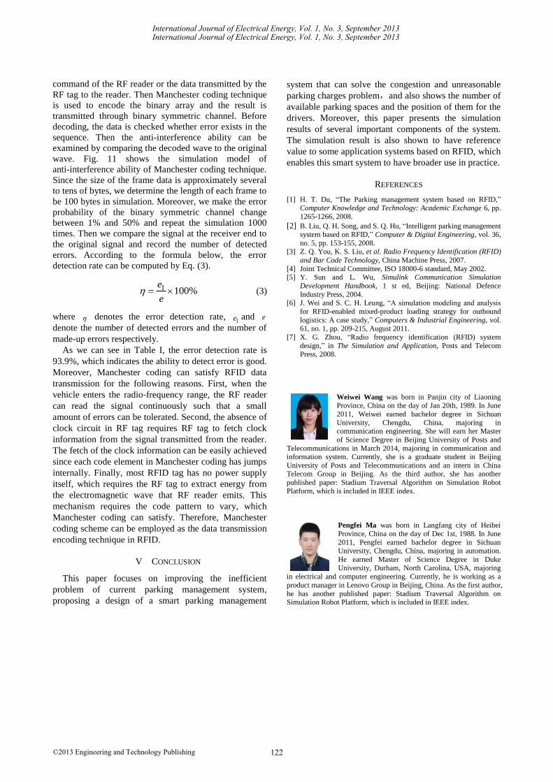
command of the RF reader or the data transmitted by the
RF tag to the reader. Then Manchester coding technique
is used to encode the binary array and the result is
transmitted through binary symmetric channel. Before
decoding, the data is checked whether error exists in the
sequence. Then the anti-interference ability can be
examined by comparing the decoded wave to the original
wave. Fig. 11 shows the simulation model of
anti-interference ability of Manchester coding technique.
Since the size of the frame data is approximately several
to tens of bytes, we determine the length of each frame to
be 100 bytes in simulation. Moreover, we make the error
probability of the binary symmetric channel change
between 1% and 50% and repeat the simulation 1000
times. Then we compare the signal at the receiver end to
the original signal and record the number of detected
errors. According to the formula below, the error
detection rate can be computed by Eq. (3).
%1001 e
e (3)
where denotes the error detection rate, 1e and e
denote the number of detected errors and the number of
made-up errors respectively.
As we can see in Table I, the error detection rate is
93.9%, which indicates the ability to detect error is good.
Moreover, Manchester coding can satisfy RFID data
transmission for the following reasons. First, when the
vehicle enters the radio-frequency range, the RF reader
can read the signal continuously such that a small
amount of errors can be tolerated. Second, the absence of
clock circuit in RF tag requires RF tag to fetch clock
information from the signal transmitted from the reader.
The fetch of the clock information can be easily achieved
since each code element in Manchester coding has jumps
internally. Finally, most RFID tag has no power supply
itself, which requires the RF tag to extract energy from
the electromagnetic wave that RF reader emits. This
mechanism requires the code pattern to vary, which
Manchester coding can satisfy. Therefore, Manchester
coding scheme can be employed as the data transmission
encoding technique in RFID.
V CONCLUSION
This paper focuses on improving the inefficient
problem of current parking management system,
proposing a design of a smart parking management
system that can solve the congestion and unreasonable
parking charges problem,and also shows the number of
available parking spaces and the position of them for the
drivers. Moreover, this paper presents the simulation
results of several important components of the system.
The simulation result is also shown to have reference
value to some application systems based on RFID, which
enables this smart system to have broader use in practice.
REFERENCES
[1] H. T. Du, “The Parking management system based on RFID,” Computer Knowledge and Technology: Academic Exchange 6, pp.
1265-1266, 2008.
[2] B. Liu, Q. H. Song, and S. Q. Hu, “Intelligent parking management system based on RFID,” Computer & Digital Engineering, vol. 36,
no. 5, pp. 153-155, 2008. [3] Z. Q. You, K. S. Liu, et al. Radio Frequency Identification (RFID)
and Bar Code Technology, China Machine Press, 2007.
[4] Joint Technical Committee, ISO 18000-6 standard, May 2002. [5] Y. Sun and L. Wu, Simulink Communication Simulation
Development Handbook, 1 st ed, Beijing: National Defence
Industry Press, 2004. [6] J. Wei and S. C. H. Leung, “A simulation modeling and analysis
for RFID-enabled mixed-product loading strategy for outbound
logistics: A case study,” Computers & Industrial Engineering, vol. 61, no. 1, pp. 209-215, August 2011.
[7] X. G. Zhou, “Radio frequency identification (RFID) system
design,” in The Simulation and Application, Posts and Telecom Press, 2008.
Weiwei Wang was born in Panjin city of Liaoning Province, China on the day of Jan 20th, 1989. In June
2011, Weiwei earned bachelor degree in Sichuan
University, Chengdu, China, majoring in communication engineering. She will earn her Master
of Science Degree in Beijing University of Posts and
Telecommunications in March 2014, majoring in communication and information system. Currently, she is a graduate student in Beijing
University of Posts and Telecommunications and an intern in China Telecom Group in Beijing. As the third author, she has another
published paper: Stadium Traversal Algorithm on Simulation Robot
Platform, which is included in IEEE index.
Pengfei Ma was born in Langfang city of Heibei
Province, China on the day of Dec 1st, 1988. In June
2011, Pengfei earned bachelor degree in Sichuan University, Chengdu, China, majoring in automation.
He earned Master of Science Degree in Duke
University, Durham, North Carolina, USA, majoring
in electrical and computer engineering. Currently, he is working as a
product manager in Lenovo Group in Beijing, China. As the first author,
he has another published paper: Stadium Traversal Algorithm on Simulation Robot Platform, which is included in IEEE index.
122
International Journal of Electrical Energy, Vol. 1, No. 3, September 2013
©2013 Engineering and Technology Publishing
International Journal of Electrical Energy, Vol. 1, No. 3, September 2013