smart mccs as a motor maintenance tool - siemens industry, inc
TRANSCRIPT
www.sea.siemens.com
A white paper issued by Siemens. ©2008 Siemens Energy & Automation, Inc. All rights reserved.
Smart MCCs as a motor maintenance tool
Siemens Energy & Automation, Inc.
www.sea.siemens.com/mcc
Smart Motor Control Centers December 1, 2008
This paper will discuss the application of Smart MCC technology to standard and predictive maintenance practices used to maximize motor life and help limit unplanned motor failure. An overview and definition of standard maintenance practices is followed by a description of information available from a Smart MCC and how this information can be used.
2
A white paper issued by Siemens. ©2008 Siemens Energy & Automation, Inc. All rights reserved.
White Paper | Smart Motor Control Center | December 1, 2008
Table of Contents
1. Introduction 1
2. Motor Maintenance Overview 2
2.1. Time-based Maintenance 4
2.2. Condition-based Maintenance 5
3. Siemens Smart MCC Overview 6
4. Siemens Smart MCC as a Motor Maintenance Tool 7
4.1. SIMOCODE Pro 8
4.1.1. SIMOCODE Pro Measured Data for Maintenance 9
4.1.2. SIMOCODE Pro Statistical Data for Maintenance 10
4.2.3 RW44 Soft-starter 11
4.2.1. RVSS Measurement Data for Maintenance 12
4.2.2. RVSS Statistical Data for Maintenance (Tab 1) 13
4.2.3. RVSS Statistical Data for Maintenance (Tab 2) 14
4.3. MM440 VFD 15
5. Summary 16
6. References 17
End of document 18
This document is not intended as a substitute for any product specific instruction or maintenance manual or literature. Always consult the manufacturer‘s product specific literature prior to working on or with motors, MCCs or related equipment.
3
1. Introduction
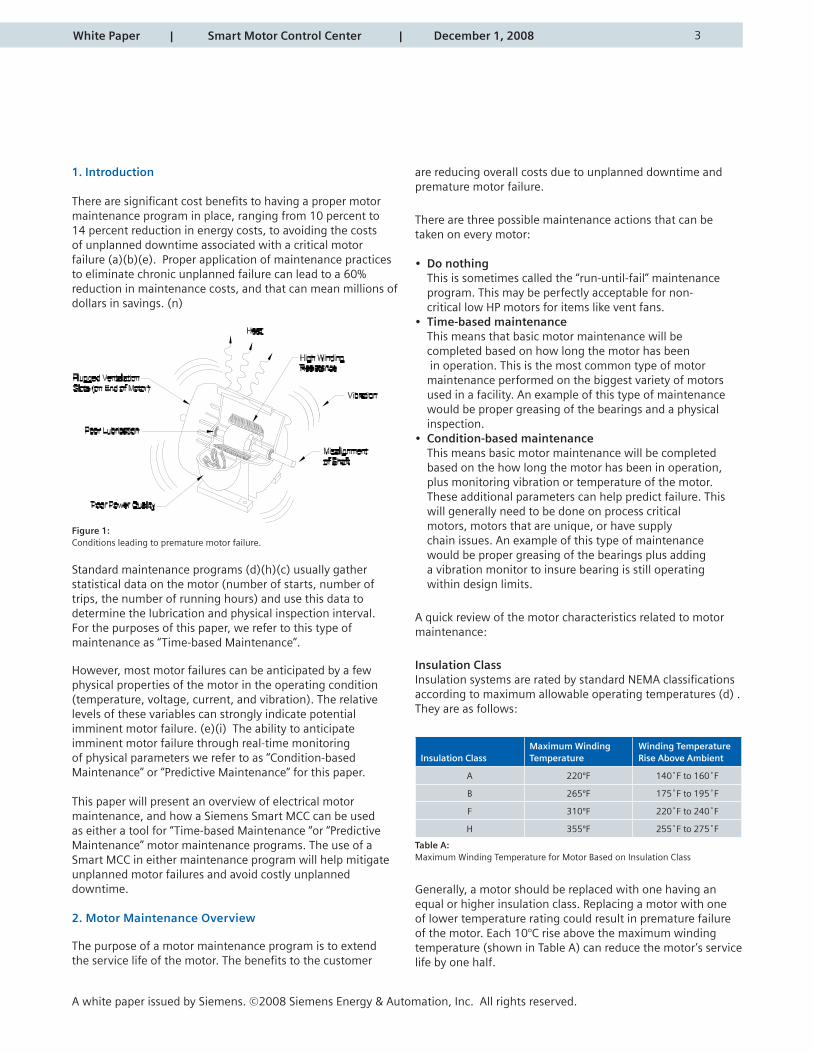
There are significant cost benefits to having a proper motor maintenance program in place, ranging from 10 percent to 14 percent reduction in energy costs, to avoiding the costs of unplanned downtime associated with a critical motor failure (a)(b)(e). Proper application of maintenance practices to eliminate chronic unplanned failure can lead to a 60% reduction in maintenance costs, and that can mean millions of dollars in savings. (n)
Figure 1: Conditions leading to premature motor failure.
Standard maintenance programs (d)(h)(c) usually gather statistical data on the motor (number of starts, number of trips, the number of running hours) and use this data to determine the lubrication and physical inspection interval. For the purposes of this paper, we refer to this type of maintenance as “Time-based Maintenance”.
However, most motor failures can be anticipated by a few physical properties of the motor in the operating condition (temperature, voltage, current, and vibration). The relative levels of these variables can strongly indicate potential imminent motor failure. (e)(i) The ability to anticipate imminent motor failure through real-time monitoring of physical parameters we refer to as “Condition-based Maintenance” or “Predictive Maintenance” for this paper.
This paper will present an overview of electrical motor maintenance, and how a Siemens Smart MCC can be used as either a tool for “Time-based Maintenance “or “Predictive Maintenance” motor maintenance programs. The use of a Smart MCC in either maintenance program will help mitigate unplanned motor failures and avoid costly unplanned downtime.
2. Motor Maintenance Overview
The purpose of a motor maintenance program is to extend the service life of the motor. The benefits to the customer
are reducing overall costs due to unplanned downtime and premature motor failure.
There are three possible maintenance actions that can be taken on every motor:
• Do nothing This is sometimes called the “run-until-fail” maintenance program. This may be perfectly acceptable for non- critical low HP motors for items like vent fans.• Time-based maintenance This means that basic motor maintenance will be completed based on how long the motor has been in operation. This is the most common type of motor maintenance performed on the biggest variety of motors used in a facility. An example of this type of maintenance would be proper greasing of the bearings and a physical inspection.• Condition-based maintenance This means basic motor maintenance will be completed based on the how long the motor has been in operation, plus monitoring vibration or temperature of the motor. These additional parameters can help predict failure. This will generally need to be done on process critical motors, motors that are unique, or have supply chain issues. An example of this type of maintenance would be proper greasing of the bearings plus adding a vibration monitor to insure bearing is still operating within design limits.
A quick review of the motor characteristics related to motor maintenance:
Insulation ClassInsulation systems are rated by standard NEMA classifications according to maximum allowable operating temperatures (d) . They are as follows:
Insulation ClassMaximum WindingTemperature
Winding TemperatureRise Above Ambient
A 220ºF 140˚F to 160˚F
B 265ºF 175˚F to 195˚F
F 310ºF 220˚F to 240˚F
H 355ºF 255˚F to 275˚F
Table A: Maximum Winding Temperature for Motor Based on Insulation Class
Generally, a motor should be replaced with one having an equal or higher insulation class. Replacing a motor with one of lower temperature rating could result in premature failure of the motor. Each 10°C rise above the maximum winding temperature (shown in Table A) can reduce the motor’s service life by one half.
A white paper issued by Siemens. ©2008 Siemens Energy & Automation, Inc. All rights reserved.
White Paper | Smart Motor Control Center | December 1, 2008
4
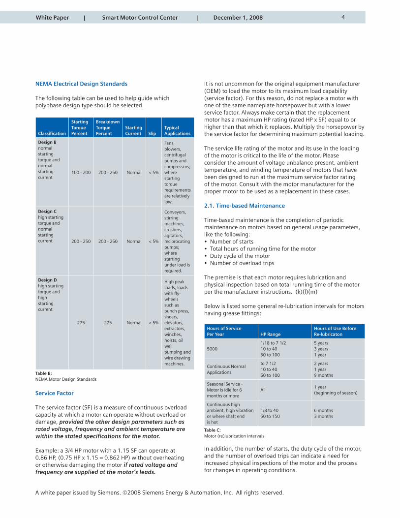
NEMA Electrical Design Standards
The following table can be used to help guide which polyphase design type should be selected.
Classification
Starting Torque Percent
Breakdown Torque Percent
Starting Current Slip
TypicalApplications
Design Bnormal startingtorque and normalstarting current
100 - 200 200 - 250 Normal < 5%
Fans, blowers, centrifugal pumps andcompressors; where starting torquerequirements are relatively low.
Design Chigh startingtorque and normalstartingcurrent 200 - 250 200 - 250 Normal < 5%
Conveyors, stirring machines, crushers, agitators, reciprocating pumps; where starting under load is required.
Design Dhigh startingtorque and highstarting current
275 275 Normal < 5%
High peak loads, loads with fly-wheels such as punch press, shears, elevators, extractors, winches, hoists, oil well pumping and wire drawing machines.
Table B:NEMA Motor Design Standards
Service Factor
The service factor (SF) is a measure of continuous overload capacity at which a motor can operate without overload or damage, provided the other design parameters such as rated voltage, frequency and ambient temperature are within the stated specifications for the motor.
Example: a 3/4 HP motor with a 1.15 SF can operate at 0.86 HP, (0.75 HP x 1.15 = 0.862 HP) without overheating or otherwise damaging the motor if rated voltage and frequency are supplied at the motor’s leads.
It is not uncommon for the original equipment manufacturer (OEM) to load the motor to its maximum load capability (service factor). For this reason, do not replace a motor with one of the same nameplate horsepower but with a lower service factor. Always make certain that the replacement motor has a maximum HP rating (rated HP x SF) equal to or higher than that which it replaces. Multiply the horsepower by the service factor for determining maximum potential loading.
The service life rating of the motor and its use in the loading of the motor is critical to the life of the motor. Please consider the amount of voltage unbalance present, ambient temperature, and winding temperature of motors that have been designed to run at the maximum service factor rating of the motor. Consult with the motor manufacturer for the proper motor to be used as a replacement in these cases.
2.1. Time-based Maintenance
Time-based maintenance is the completion of periodic maintenance on motors based on general usage parameters, like the following:• Number of starts• Total hours of running time for the motor• Duty cycle of the motor• Number of overload trips
The premise is that each motor requires lubrication and physical inspection based on total running time of the motor per the manufacturer instructions. (k)(l)(m)
Below is listed some general re-lubrication intervals for motors having grease fittings:
Hours of Service Per Year HP Range
Hours of Use BeforeRe-lubricaton
50001/18 to 7 1/210 to 4050 to 100
5 years3 years1 year
Continuous NormalApplications
to 7 1/210 to 4050 to 100
2 years1 year9 months
Seasonal Service - Motor is idle for 6 months or more
All1 year (beginning of season)
Continuous high ambient, high vibration or where shaft end is hot
1/8 to 4050 to 150
6 months3 months
Table C:Motor (re)lubrication intervals
In addition, the number of starts, the duty cycle of the motor, and the number of overload trips can indicate a need for increased physical inspections of the motor and the process for changes in operating conditions.
A white paper issued by Siemens. ©2008 Siemens Energy & Automation, Inc. All rights reserved.
White Paper | Smart Motor Control Center | December 1, 2008
5
2.2 Condition-based Maintenance
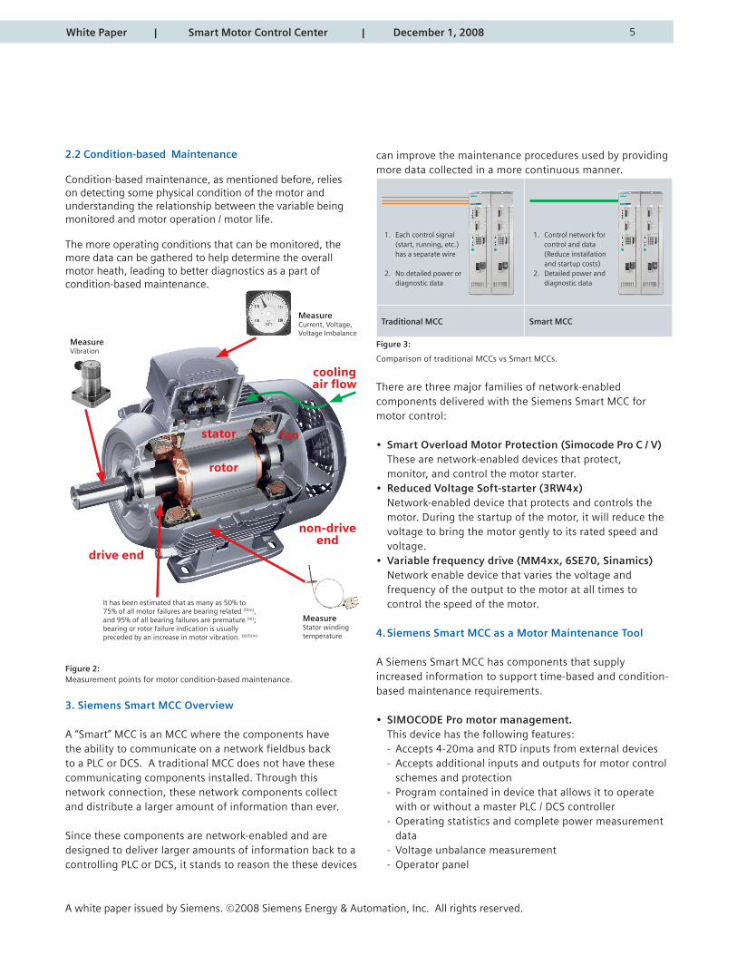
Condition-based maintenance, as mentioned before, relies on detecting some physical condition of the motor and understanding the relationship between the variable being monitored and motor operation / motor life.
The more operating conditions that can be monitored, the more data can be gathered to help determine the overall motor heath, leading to better diagnostics as a part of condition-based maintenance.
Figure 2:Measurement points for motor condition-based maintenance.
3. Siemens Smart MCC Overview
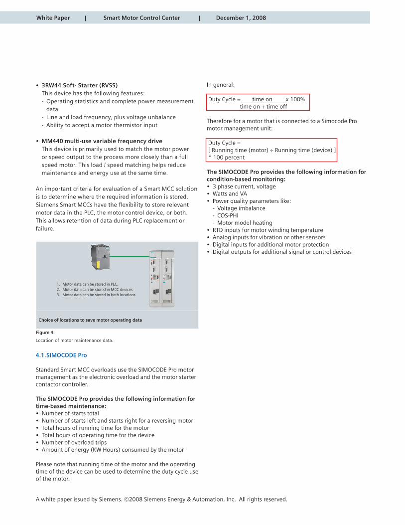
A “Smart” MCC is an MCC where the components have the ability to communicate on a network fieldbus back to a PLC or DCS. A traditional MCC does not have these communicating components installed. Through this network connection, these network components collect and distribute a larger amount of information than ever.
Since these components are network-enabled and are designed to deliver larger amounts of information back to a controlling PLC or DCS, it stands to reason the these devices
can improve the maintenance procedures used by providing more data collected in a more continuous manner.
Traditional MCC Smart MCC
Figure 3:
Comparison of traditional MCCs vs Smart MCCs.
There are three major families of network-enabled components delivered with the Siemens Smart MCC for motor control:
• Smart Overload Motor Protection (Simocode Pro C / V) These are network-enabled devices that protect, monitor, and control the motor starter.• Reduced Voltage Soft-starter (3RW4x) Network-enabled device that protects and controls the motor. During the startup of the motor, it will reduce the voltage to bring the motor gently to its rated speed and voltage.• Variable frequency drive (MM4xx, 6SE70, Sinamics) Network enable device that varies the voltage and frequency of the output to the motor at all times to control the speed of the motor.
4. Siemens Smart MCC as a Motor Maintenance Tool
A Siemens Smart MCC has components that supply increased information to support time-based and condition-based maintenance requirements.
• SIMOCODE Pro motor management. This device has the following features: - Accepts 4-20ma and RTD inputs from external devices - Accepts additional inputs and outputs for motor control schemes and protection - Program contained in device that allows it to operate with or without a master PLC / DCS controller - Operating statistics and complete power measurement data - Voltage unbalance measurement - Operator panel
A white paper issued by Siemens. ©2008 Siemens Energy & Automation, Inc. All rights reserved.
White Paper | Smart Motor Control Center | December 1, 2008
1. Each control signal (start, running, etc.) has a separate wire
2. No detailed power or diagnostic data
1. Control network for control and data (Reduce installation and startup costs)2. Detailed power and diagnostic data
rotor
stator fan
coolingair flow
non-driveend
drive end
It has been estimated that as many as 50% to75% of all motor failures are bearing related (fXm), and 95% of all bearing failures are premature (m); bearing or rotor failure indication is usually preceded by an increase in motor vibration. (k)(l)(m)
MeasureStator windingtemperature
MeasureVibration
MeasureCurrent, Voltage, Voltage Imbalance
In general:
Duty Cycle = time on x 100% time on + time off
Therefore for a motor that is connected to a Simocode Pro motor management unit:
Duty Cycle = [ Running time (motor) ÷ Running time (device) ] * 100 percent
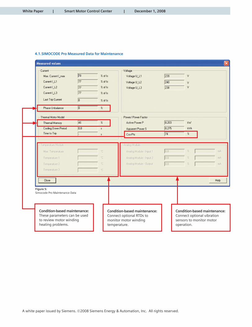
The SIMOCODE Pro provides the following information for condition-based monitoring:• 3 phase current, voltage• Watts and VA• Power quality parameters like: - Voltage imbalance - COS-PHI - Motor model heating• RTD inputs for motor winding temperature• Analog inputs for vibration or other sensors• Digital inputs for additional motor protection• Digital outputs for additional signal or control devices
White Paper | Smart Motor Control Center | December 1, 2008
A white paper issued by Siemens. ©2008 Siemens Energy & Automation, Inc. All rights reserved.
• 3RW44 Soft- Starter (RVSS) This device has the following features: - Operating statistics and complete power measurement data - Line and load frequency, plus voltage unbalance - Ability to accept a motor thermistor input
• MM440 multi-use variable frequency drive This device is primarily used to match the motor power or speed output to the process more closely than a full speed motor. This load / speed matching helps reduce maintenance and energy use at the same time.
An important criteria for evaluation of a Smart MCC solution is to determine where the required information is stored. Siemens Smart MCCs have the flexibility to store relevant motor data in the PLC, the motor control device, or both. This allows retention of data during PLC replacement or failure.
Choice of locations to save motor operating data
Figure 4:
Location of motor maintenance data.
4.1. SIMOCODE Pro
Standard Smart MCC overloads use the SIMOCODE Pro motor management as the electronic overload and the motor starter contactor controller.
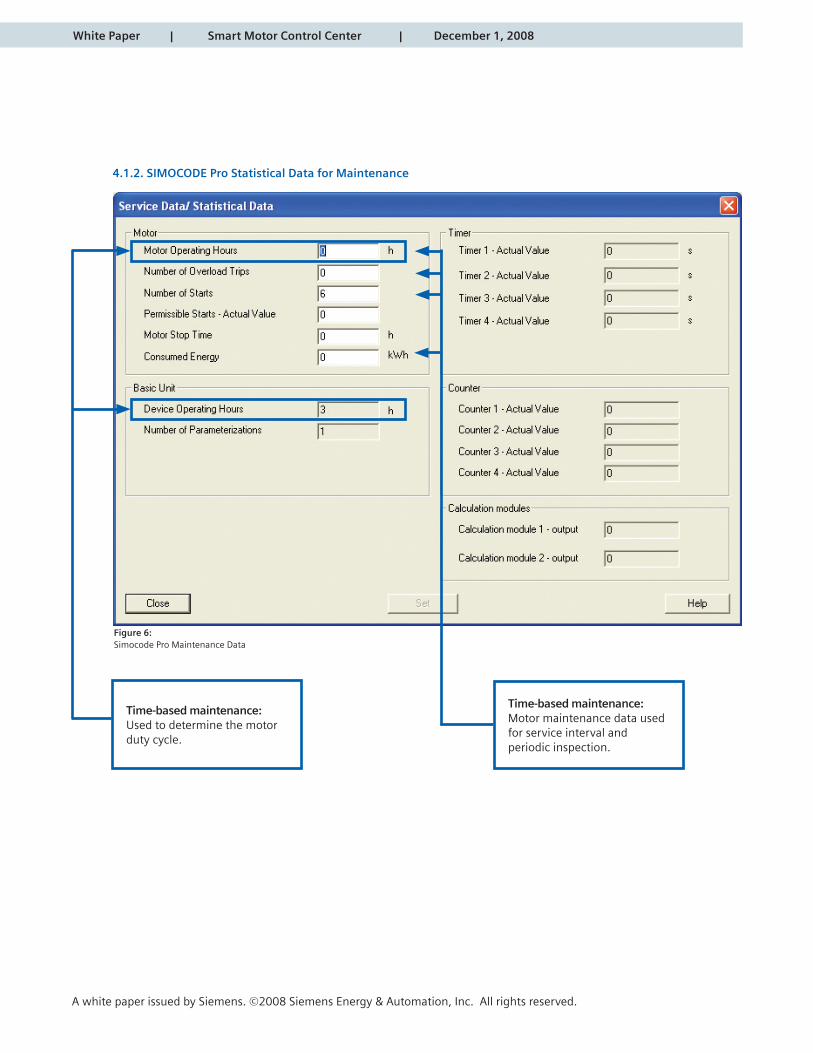
The SIMOCODE Pro provides the following information for time-based maintenance:• Number of starts total• Number of starts left and starts right for a reversing motor• Total hours of running time for the motor• Total hours of operating time for the device• Number of overload trips• Amount of energy (KW Hours) consumed by the motor
Please note that running time of the motor and the operating time of the device can be used to determine the duty cycle use of the motor.
1. Motor data can be stored in PLC.2. Motor data can be stored in MCC devices3. Motor data can be stored in both locations
White Paper | Smart Motor Control Center | December 1, 2008
A white paper issued by Siemens. ©2008 Siemens Energy & Automation, Inc. All rights reserved.
4.1. SIMOCODE Pro Measured Data for Maintenance
Condition-based maintenance:These parameters can be used to review motor winding heating problems.
Condition-based maintenance:Connect optional RTDs to monitor motor windingtemperature.
Condition-based maintenance:Connect optional vibration sensors to monitor motor operation.
Figure 5:Simocode Pro Maintenance Data
White Paper | Smart Motor Control Center | December 1, 2008
A white paper issued by Siemens. ©2008 Siemens Energy & Automation, Inc. All rights reserved.
4.1.2. SIMOCODE Pro Statistical Data for Maintenance
Time-based maintenance:Used to determine the motor duty cycle.
Time-based maintenance:Motor maintenance data used for service interval and periodic inspection.
Figure 6:Simocode Pro Maintenance Data
White Paper | Smart Motor Control Center | December 1, 2008
A white paper issued by Siemens. ©2008 Siemens Energy & Automation, Inc. All rights reserved.
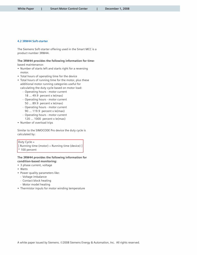
4.2 3RW44 Soft-starter
The Siemens Soft-starter offering used in the Smart MCC is a product number 3RW44.
The 3RW44 provides the following information for time-based maintenance:• Number of starts left and starts right for a reversing motor. • Total hours of operating time for the device• Total hours of running time for the motor, plus these additional motor running categories useful for calculating the duty cycle based on motor load: - Operating hours - motor current 18 ... 49.9 percent x Ie(max) - Operating hours - motor current 50 ... 89.9 percent x Ie(max) - Operating hours - motor current 90 ... 119.9 percent x Ie(max) - Operating hours - motor current 120 ... 1000 percent x Ie(max) • Number of overload trips
Similar to the SIMOCODE Pro device the duty cycle is calculated by:
Duty Cycle = [ Running time (motor) ÷ Running time (device) ] * 100 percent
The 3RW44 provides the following information for condition-based monitoring:• 3 phase current, voltage• Watts • Power quality parameters like: - Voltage imbalance - Contact block heating - Motor model heating• Thermistor inputs for motor winding temperature

White Paper | Smart Motor Control Center | December 1, 2008
A white paper issued by Siemens. ©2008 Siemens Energy & Automation, Inc. All rights reserved.
4.2. 1. RVSS Measurement Data for Maintenance
Condition-based maintenance:Used to determine the voltage and current unbalance effecton the motor windings.
Figure 7:RVSS Measured Real-time Data
White Paper | Smart Motor Control Center | December 1, 2008
A white paper issued by Siemens. ©2008 Siemens Energy & Automation, Inc. All rights reserved.
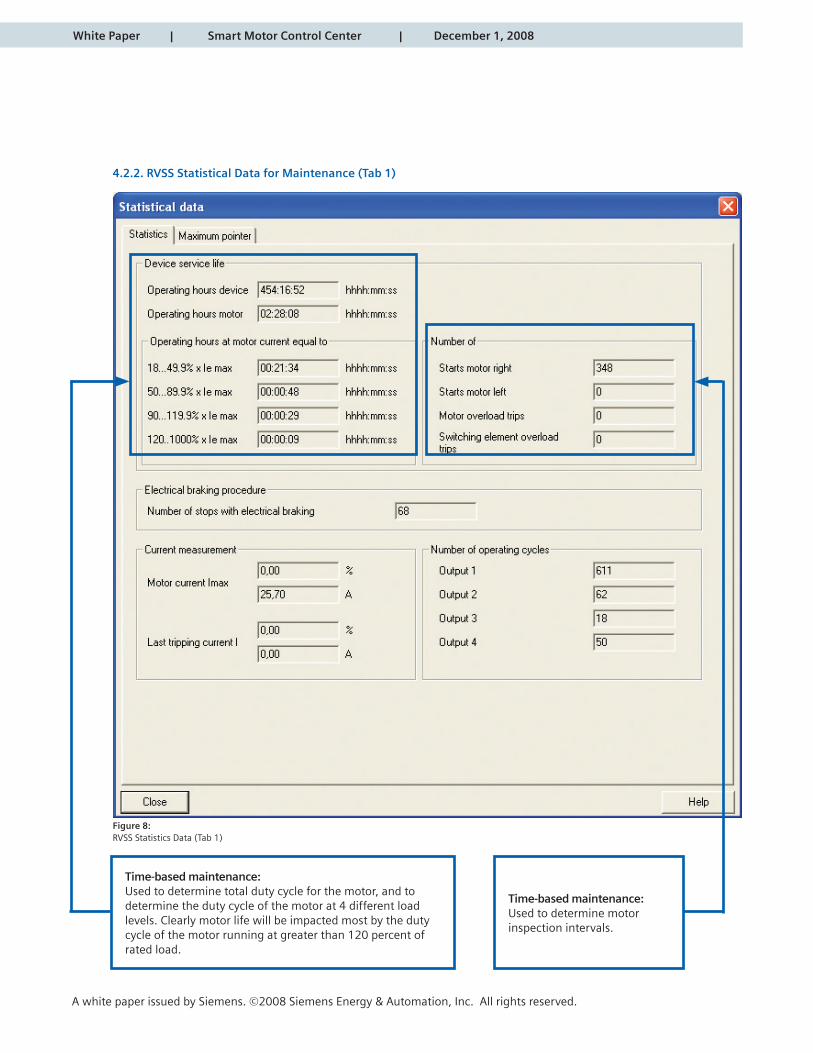
4.2.2. RVSS Statistical Data for Maintenance (Tab 1)
Time-based maintenance:Used to determine total duty cycle for the motor, and to determine the duty cycle of the motor at 4 different load levels. Clearly motor life will be impacted most by the duty cycle of the motor running at greater than 120 percent of rated load.
Time-based maintenance:Used to determine motorinspection intervals.
Figure 8:RVSS Statistics Data (Tab 1)
White Paper | Smart Motor Control Center | December 1, 2008
A white paper issued by Siemens. ©2008 Siemens Energy & Automation, Inc. All rights reserved.
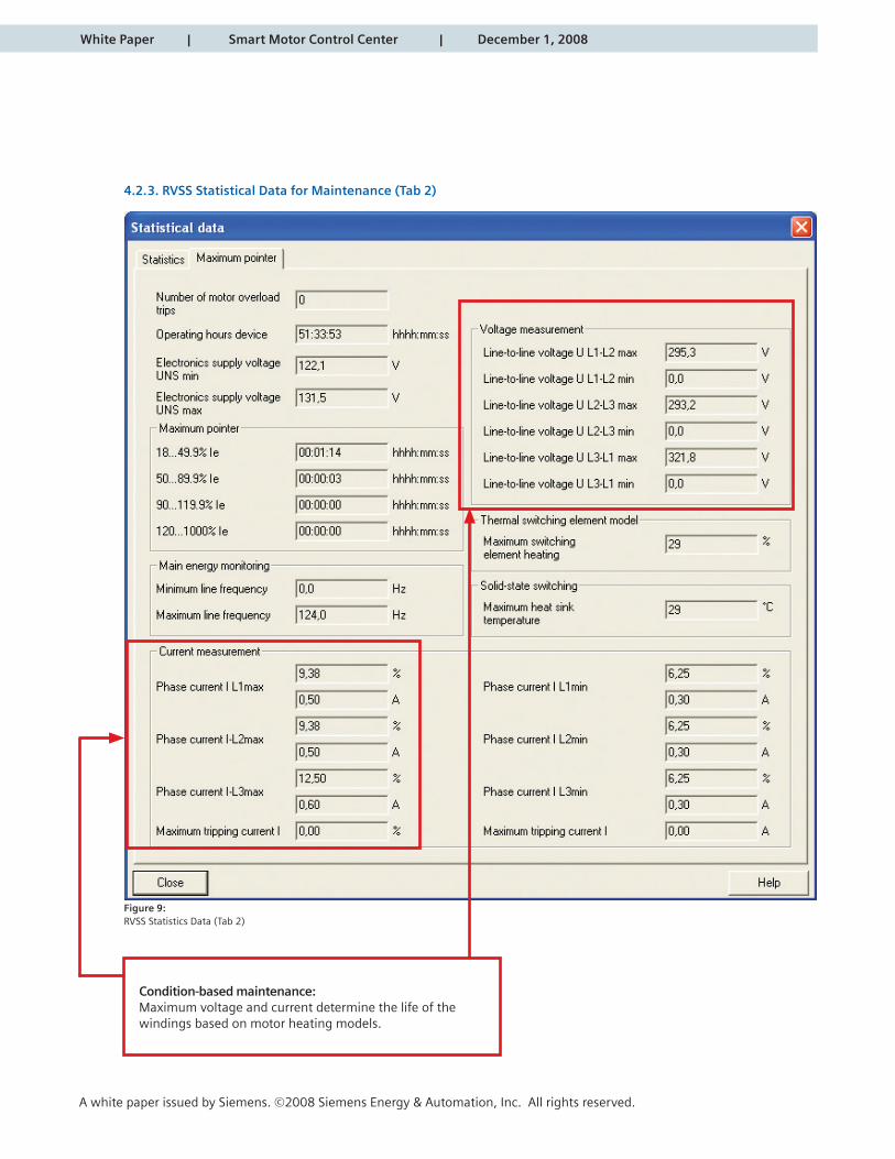
4.2. 3. RVSS Statistical Data for Maintenance (Tab 2)
Condition-based maintenance:Maximum voltage and current determine the life of thewindings based on motor heating models.
Figure 9:RVSS Statistics Data (Tab 2)

White Paper | Smart Motor Control Center | December 1, 2008
A white paper issued by Siemens. ©2008 Siemens Energy & Automation, Inc. All rights reserved.
4.3 MM440 VFD
The MM440 VFD provides the following information for time-based maintenance:• Total hours of running time for the motor• Number of overload trips
The MM440 VFD provides the following information for conditioned-based maintenance:• 3 phase current, voltage, and power• Power Factor, consumed energy• Resistance of rotor and stator windings• Thermistor input for motor winding temperature.
Figure 10:MM440 Motor Operational Data
Drive alarms and warnings
Operational data for motor performance evaluation
6
5. Summary
There are significant cost benefits from employing a motor maintenance program. These cost benefits are due to a reduction of unplanned downtime to reduced energy costs. A time-based maintenance program gathers statistical motor data (number of starts, running hours, etc) and utilizes this information to determine motor physical inspection and lubrication schedules. A condition-based maintenance program gathers additional real-time physical parameters (temperature, current, voltage, vibration) to anticipate imminent motor failures and proactively address motor issues.
Siemens Smart MCCs support either type of maintenance program, with the following features:• Ability to collect real-time data from the motor controlling device• Ability to have all relevant motor data read by the PLC or DCS controller and presented on the operator HMI. This data can then be printed, avoiding operator manual data collection processes.• Ability to gather data for time-based and condition-based motor maintenance.The time-based data is automatically included on all motor control devices, but the Simocode Pro can handle optional RTDs and vibration sensors for condition-based monitoring programs.
Siemens Smart MCCs are a cost effective addition to any existing maintenance program, as well as a key enabler to initiate new motor maintenance programs.
Unique features of Siemens Smart MCC with Profibus-DP communications include:• Motor data is stored in the motor control devices• Independent operation of the motor control devices to reduce PLC programming• Extended data and diagnostics are available for quicker troubleshooting
A white paper issued by Siemens. ©2008 Siemens Energy & Automation, Inc. All rights reserved.
White Paper | Smart Motor Control Center | December 1, 2008

White Paper | Smart Motor Control Center | December 1, 2008
A white paper issued by Siemens. ©2008 Siemens Energy & Automation, Inc. All rights reserved.
6. References
a.) “Understanding Downtime”, www.visionsolutions.com, May 2006
b.) “A Simple Way to Estimate the Cost of Downtime”, http://roc.cs.berkeley.edu/talks/LISA/ppt, Nov 2002
c.) “Motors: Planning for motor failure”, E-source Companies, LLC., 2006
d.) “Efficiency Opportunities through Motor Maintenance”, Pacific Gas and Electric Company, Apr 1997
e.) “Test Methods for Determining the Impact of Motor Condition on Motor Efficiency and Reliability” ALL-TEST Pro, LLC., (Undated)
f.) “Extend the operating life of your motor”, U.S. Department of Energy, Sep 2005
g.) “Eliminate Voltage Unbalance”, U.S. Department of Energy, Sep 2005
h.) “FAQ about Drive Technology”, Siemens AG, 2008
i.) “Prognostics and Condition-based Maintenance”, Pacific Northwest National Laboratory, PNNL-SA-36771, (Undated)
j.) “Automated Bearing Wear Detection”, DLI Engineering Corporation, 2004
k.) “Application Manual for NEMA Motors”, http://www.2.sea.siemens.com/NR/rdonlyres/1EE7928A-37F4-44F0-9342- C35844C09FE3/0/AppManSectionAIIRev1061608.pdf, 2008
l.) “Evaluation of antifriction bearing lubrication methods on motor life-cycle cost”, Siemens AG, Dec. 1999
m.) “Guide to Electric Motor Bearing Lubrication”, ExxonMobil, (Undated)
n.) “Hidden Treasure: Eliminating Chronic Failures Can Cut Maintenance Costs Up to 60%”. Plant Engineering Magazine, Nov 1996
White Paper | Smart Motor Control Center | December 1, 2008
A white paper issued by Siemens. ©2008 Siemens Energy & Automation, Inc. All rights reserved.
www.sea.siemens.com
All rights reserved. All trademarks use are owned by Siemens or their respective owners.
© 2008 Siemens Energy & Automation, Inc.
Siemens Energy & Automation, Inc.Industry SectorDrive Technologies and Industry Automation3333 Old Milton ParkwayAlpharetta, GA 30005Printed in USA