smart management for real-time telemetry...
TRANSCRIPT
Smart Management for Real-Time Telemetry (SMRT)
Enabling remote management and monitoring of ordinary household devices.
Team:
Henry Spang
Ethan Peters
Ryan Rawlins
Don Luchini
4/30/2013
Collaborators:
Dr. Robert J. Bowman - [email protected]
Ken Snyder - [email protected]
Website: http://projects.ce.rit.edu/edge/SMRT/private/index.html
Smart Management for Real-Time Telemetry – Page 1
Contents Needs Statement .......................................................................................................................................... 2
Objective Statement ..................................................................................................................................... 2
Mechanism of Operation .............................................................................................................................. 2
Functional Diagram ....................................................................................................................................... 3
Requirements Specification .......................................................................................................................... 4
Marketing Requirements .......................................................................................................................... 4
Engineering Requirements ........................................................................................................................ 4
Concept Selection ......................................................................................................................................... 6
Survey of Existing Systems ........................................................................................................................ 6
Concepts Considered and Chosen ............................................................................................................ 6
Design ............................................................................................................................................................ 9
System design ........................................................................................................................................... 9
Subsystems ............................................................................................................................................. 10
Cloud Server ........................................................................................................................................ 10
SMRT Hub ............................................................................................................................................ 11
SMRT Adapter ..................................................................................................................................... 12
Typical User Workflows .......................................................................................................................... 13
User views statistics for adapter ......................................................................................................... 13
User turns device on or off ................................................................................................................. 14
Transmission of a Reading .................................................................................................................. 15
Adapter is associated with hub ........................................................................................................... 16
Engineering Standards ............................................................................................................................ 17
Multidisciplinary Aspects ........................................................................................................................ 17
Background ............................................................................................................................................. 18
Outside Contributors .............................................................................................................................. 18
Constraints and Considerations .................................................................................................................. 19
Cost Estimates ............................................................................................................................................. 20
Testing Strategy .......................................................................................................................................... 20
Risks ............................................................................................................................................................ 39
Milestone Chart .......................................................................................................................................... 40

Smart Management for Real-Time Telemetry – Page 2
Needs Statement Imagine an all-too-familiar usage scenario: after leaving for work, a homeowner realizes that he or she
has left the home's air conditioner turned up. The homeowner has no knowledge of the power draw of
their home's air conditioning system, or how much their blunder could cost them at the end of the
month. Furthermore, they have no means to remotely shut off the air conditioner. A system is needed
to put the homeowner in control of the energy-consuming devices in their home.
Objective Statement We propose a low-cost system that allows residential, non-technical users to monitor their electricity
usage, and remotely control electricity-consuming devices within their home. The user will place a small
device between the consumer and a wall outlet, which will make the device accessible to a Web-based
or smartphone interface.
Mechanism of Operation A device, the SMRT adapter, will be placed between a wall outlet and a household device. This device
will measure the current through the connection using a current transformer, and report it to a hub unit
at regular intervals using an XBee radio. Additionally, this device will be able to open or close the
connection between the wall and the device by means of a solid-state relay when sent a command to do
so from a cloud-hosted server, which will be controlled via a user-friendly interface.

Smart Management for Real-Time Telemetry – Page 3
Functional Diagram
Figure 1: Top-level functional diagram of entire system
The server has a one-to-many relationship with a variable number hubs, which in turn have a one-to-
many relationship with a variable number of SMRT adapters. SMRT adapters communicate via ZigBee
with the hub, while the hub communicates with the server over Ethernet. The server is able to take both
current and historical data, and make them available via a web API to clients, which present them in a
human-readable interface to a user.

Smart Management for Real-Time Telemetry – Page 4
Requirements Specification
Marketing Requirements 1. Inexpensive
2. Robust and fault-tolerant
3. Easy to use and install
4. Low power
5. Accurate
6. Low delay
7. Not detrimental to user environment
Engineering Requirements
Marketing
Requirements
Engineering Requirement Justification
1 The cost of an individual SMRT adapter
should not exceed $100.
The cost of an adapter should not be
greater than the cost of a full-fledged
smart device.
2,3 An adapter will be able to withstand a
four-foot drop onto concrete.
Four feet is about the height of a
counter top.
1,4 An adapter should draw less than five
watts of power.
The device cannot draw more power
than the product it is attached to (e.g.,
LED light bulb).
6 The total delay from hitting an on/off
button on a client on a local network and a
device turning off should be less than one
second. The total delay from restoring
power to a registered adapter to it being
able to receive controls should be less than
ten seconds.
One second is roughly the startup time
of a modern computer monitor; it
should not take more time to transmit
the signal than for the action to occur.
1 The cost of the hub should not exceed
$200.
This is about the cost of a low-end
general-purpose computing device
that could be used as a server.
Smart Management for Real-Time Telemetry – Page 5
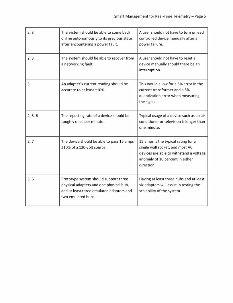
2, 3 The system should be able to come back
online autonomously to its previous state
after encountering a power fault.
A user should not have to turn on each
controlled device manually after a
power failure.
2, 3 The system should be able to recover from
a networking fault.
A user should not have to reset a
device manually should there be an
interruption.
5 An adapter’s current reading should be
accurate to at least ±10%.
This would allow for a 5% error in the
current transformer and a 5%
quantization error when measuring
the signal.
4, 5, 6 The reporting rate of a device should be
roughly once per minute.
Typical usage of a device such as an air
conditioner or television is longer than
one minute.
2, 7 The device should be able to pass 15 amps
±10% of a 120-volt source.
15 amps is the typical rating for a
single wall socket, and most AC
devices are able to withstand a voltage
anomaly of 10 percent in either
direction.
5, 6 Prototype system should support three
physical adapters and one physical hub,
and at least three emulated adapters and
two emulated hubs.
Having at least three hubs and at least
six adapters will assist in testing the
scalability of the system.
Smart Management for Real-Time Telemetry – Page 6
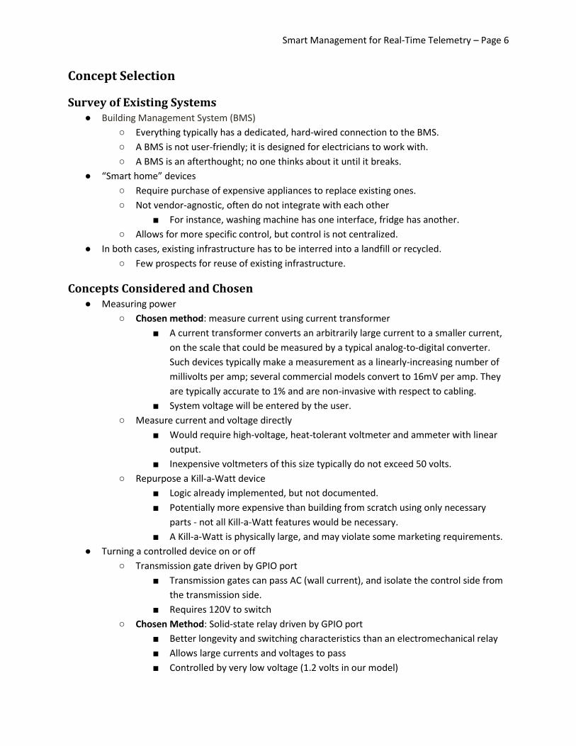
Concept Selection
Survey of Existing Systems ● Building Management System (BMS)
○ Everything typically has a dedicated, hard-wired connection to the BMS.
○ A BMS is not user-friendly; it is designed for electricians to work with.
○ A BMS is an afterthought; no one thinks about it until it breaks.
● “Smart home” devices
○ Require purchase of expensive appliances to replace existing ones.
○ Not vendor-agnostic, often do not integrate with each other
■ For instance, washing machine has one interface, fridge has another.
○ Allows for more specific control, but control is not centralized.
● In both cases, existing infrastructure has to be interred into a landfill or recycled.
○ Few prospects for reuse of existing infrastructure.
Concepts Considered and Chosen ● Measuring power
○ Chosen method: measure current using current transformer
■ A current transformer converts an arbitrarily large current to a smaller current,
on the scale that could be measured by a typical analog-to-digital converter.
Such devices typically make a measurement as a linearly-increasing number of
millivolts per amp; several commercial models convert to 16mV per amp. They
are typically accurate to 1% and are non-invasive with respect to cabling.
■ System voltage will be entered by the user.
○ Measure current and voltage directly
■ Would require high-voltage, heat-tolerant voltmeter and ammeter with linear
output.
■ Inexpensive voltmeters of this size typically do not exceed 50 volts.
○ Repurpose a Kill-a-Watt device
■ Logic already implemented, but not documented.
■ Potentially more expensive than building from scratch using only necessary
parts - not all Kill-a-Watt features would be necessary.
■ A Kill-a-Watt is physically large, and may violate some marketing requirements.
● Turning a controlled device on or off
○ Transmission gate driven by GPIO port
■ Transmission gates can pass AC (wall current), and isolate the control side from
the transmission side.
■ Requires 120V to switch
○ Chosen Method: Solid-state relay driven by GPIO port
■ Better longevity and switching characteristics than an electromechanical relay
■ Allows large currents and voltages to pass
■ Controlled by very low voltage (1.2 volts in our model)

Smart Management for Real-Time Telemetry – Page 7
● Wall Adapter Construction
○ Chosen Method: Repurpose an existing electronic casing fitted with a custom PCB
■ Cheap and tested system
■ PCB increases physical stability
○ Buy off the shelf electronic casing
■ Cheap but not free
■ Can be fitted closely to our dimensions
○ Build a custom enclosure
■ Can be fitted exactly to our dimensions
● Wireless communications between adapter and hub
○ Chosen Method: ZigBee
■ Low power; less complex than Wi-Fi
■ Requires creation of independent mesh network within a residence
○ Wi-Fi/Ethernet
■ Uses existing infrastructure / backhaul
■ Wi-Fi already deployed sufficiently robustly in residential settings
● Cloud-based virtual machine
○ Chosen Method: Apache Tomcat + Java EE
■ Uses Apache Coyote backend (same security & modularity as Apache httpd)
■ Allows us to utilize rich Java Cryptography API and modules for MySQL
○ Apache httpd + PHP
■ Popular “LAMP Stack” - lots of documentation, community support
■ PHP requires add-on libraries for heavy security usage
■ PHP is also not recommended for high-performance scenarios
○ nginx + PHP
■ nginx is a much higher-performance HTTP server than Apache httpd
■ Does not share the same support community
■ Not module-compatible with Apache
● Hub module
○ SoC running Linux
■ Many tasks already taken care of: DBMS, multitasking, Web server, etc.
■ Inexpensive, easy to interface with Ethernet and XBee modules
○ Microcontroller
■ Lowest power footprint and cost
■ Highest development time - would require the most code to be written from
scratch
■ Potential performance issues depending on speed of microcontroller
○ Chosen Method: Raspberry Pi
■ Familiar environment (can run Linux); easiest to prototype with
■ Very inexpensive, only $35
■ ARM Developer Day-capable
■ Slice of Pi allows for interfacing with XBees easily
Smart Management for Real-Time Telemetry – Page 8
● Communications between Hub and Cloud Server
○ Chosen Method: ejabberd (XMPP server)
■ ejabberd written in Erlang, high-performance runtime developed by Ericsson for
mobile phone base stations
■ ejabberd scales into the hundreds of thousands of users per instance
■ Supports third-party authentication modules to prevent us from having to
perform database replication
○ SSH
■ Very secure (public key-based), built-in authentication
■ Difficult to initiate an SSH connection backwards, from hub to server
● Required for traversing a firewall
○ Dumb TCP pipe, custom protocol
■ Could create protocol exactly to our needs
■ Not recommended to reinvent the wheel, especially for authentication
● Data Frontend
○ Chosen Method: AJAX-based API
■ Would allow for Web interface and smartphone interface to be created using
common backend
■ Software infrastructure is very mature - PHP, Java EE, etc.
■ Allows third-party clients to be created and the platform to be extended
● User Interface
○ Chosen Method: Smartphone app and Web interface
■ Having two distinct interfaces allows for each to be cater-designed to a
particular device format
○ Web interface only
■ Common codebase for user interface; consistent user experience.
■ Difficult to design a common UI workable on both a smartphone and a desktop.

Smart Management for Real-Time Telemetry – Page 9
Design
System design
Figure 2: Overall system design
The overall system, shown in Figure 2, consists of a variable number of SMRT adapters, which are
connected to a single SMRT hub located within a residence or business. Each SMRT hub, in turn, will
communicate with the SMRT server, which offers centralized management of all controlled devices.
This segmented approach provides a great deal of abstraction among segments in the system. For
instance, SMRT adapters need not have any understanding of how the SMRT server works, or how to
address it, while the SMRT server does not need to communicate directly with the adapters. Because of
this layer of abstraction, the product can be rapidly built concurrently by several team members, as the
hub is nothing more than a mediator that can be emulated with relative ease.
Smart Management for Real-Time Telemetry – Page 10
Subsystems
Cloud Server
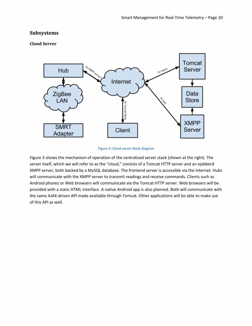
Figure 3: Cloud server block diagram
Figure 3 shows the mechanism of operation of the centralized server stack (shown at the right). The
server itself, which we will refer to as the “cloud,” consists of a Tomcat HTTP server and an ejabberd
XMPP server, both backed by a MySQL database. The frontend server is accessible via the Internet. Hubs
will communicate with the XMPP server to transmit readings and receive commands. Clients such as
Android phones or Web browsers will communicate via the Tomcat HTTP server. Web browsers will be
provided with a static HTML interface. A native Android app is also planned. Both will communicate with
the same AJAX-driven API made available through Tomcat. Other applications will be able to make use
of this API as well.
Smart Management for Real-Time Telemetry – Page 11
SMRT Hub
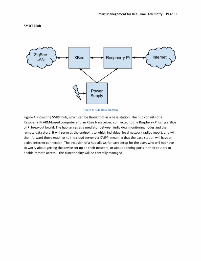
Figure 4: Hub block diagram
Figure 4 shows the SMRT hub, which can be thought of as a base station. The hub consists of a
Raspberry Pi ARM-based computer and an XBee transceiver, connected to the Raspberry Pi using a Slice
of Pi breakout board. The hub serves as a mediator between individual monitoring nodes and the
remote data store. It will serve as the endpoint to which individual local network radios report, and will
then forward those readings to the cloud server via XMPP, meaning that the base station will have an
active Internet connection. The inclusion of a hub allows for easy setup for the user, who will not have
to worry about getting the device set up on their network, or about opening ports in their routers to
enable remote access – this functionality will be centrally managed.

Smart Management for Real-Time Telemetry – Page 12
SMRT Adapter
Figure 5: SMRT Adapter block diagram
The SMRT adapter, shown in Figure 5, consists of a current transformer, a solid-state relay, and an XBee
transceiver. It sits between a device and a wall outlet. It will serve two primary purposes. First, it will
non-invasively make measurements of the current running through it using a current transformer, to
facilitate monitoring of a device’s energy usage. Second, it will allow a user to turn the device on or off
remotely, by toggling a solid-state relay placed inline with the AC mains.
Figure 6: SMRT Adapter circuit
Figure 6 shows the circuit schematic for the SMRT adapter, including its power supply, current
transformer, solid-state relay, and XBee radio. The XBee is powered off the wall voltage after being
Smart Management for Real-Time Telemetry – Page 13
passed through a voltage transformer. The current given to the ADC is sent through a current
transformer to and then a bridge rectifier in order to transfer it to a DC signal. The current is measured
from before the relay so the draw of the XBee can also be measured. The relay is seen as a combination
of an opto-isolator and two MOSFETs. The control signal is applied to the LED which applies voltage to
the gate of the transistor, thus allowing current flow.
Typical User Workflows
User views statistics for adapter
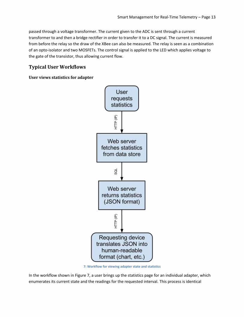
7: Workflow for viewing adapter state and statistics
In the workflow shown in Figure 7, a user brings up the statistics page for an individual adapter, which
enumerates its current state and the readings for the requested interval. This process is identical

Smart Management for Real-Time Telemetry – Page 14
regardless of what client the user made the request from, due to the abstracting web API, made
available through Tomcat over HTTP. From here, Tomcat runs the appropriate queries on the MySQL
backend, and formats the output as JSON data, which gets sent back to the user over HTTP. The client is
then tasked with interpreting this data and translating it into a human-readable format, such as a chart
or table.
User turns device on or off
Figure 8: Workflow for turning a device on or off.
In the workflow shown in Figure 8, a user chooses to turn a controlled device on or off. The client uses
the Web API to trigger a control message. From here, Tomcat sends the control command to the
appropriate hub over XMPP. If the hub receives the message successfully, it will relay the message to
the XBee on the adapter, which will toggle its solid-state relay. The hub will also send an
Smart Management for Real-Time Telemetry – Page 15
acknowledgement back to the server via XMPP. Upon receipt of this acknowledgement, the server will
update the device state record in the MySQL database to reflect the new device state.
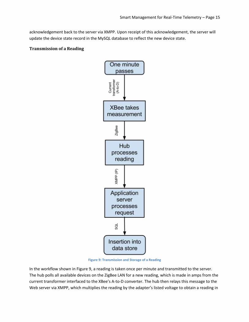
Transmission of a Reading
Figure 9: Transmission and Storage of a Reading
In the workflow shown in Figure 9, a reading is taken once per minute and transmitted to the server.
The hub polls all available devices on the ZigBee LAN for a new reading, which is made in amps from the
current transformer interfaced to the XBee’s A-to-D converter. The hub then relays this message to the
Web server via XMPP, which multiplies the reading by the adapter’s listed voltage to obtain a reading in

Smart Management for Real-Time Telemetry – Page 16
watts. The reading is then stored in the MySQL data store, tagged with the adapter ID and the
timestamp.
Adapter is associated with hub
Figure 10: Workflow for associating an adapter with a hub
Each adapter has a unique 64-bit unique identifier, based on the XBee radio’s UID. In Figure 10, a user
enters the 16-character hexadecimal representation of this UID into the Web interface, which transmits
it to the appropriate hub. The hub temporarily switches to the XBee network with name “SMRTReg,”
which has an encryption key consisting of the UID concatenated with itself, making 128 bits. The hub
transmits the proper network name and encryption key to the adapter, which acknowledges that it has
received the message and resets. The hub returns to its original network, and begins accepting
messages from the newly-registered adapter and passing them on to the Web server.
Smart Management for Real-Time Telemetry – Page 17
This method was chosen to eliminate the necessity of requiring a user to pair the adapter with the hub
manually, which would have compromised the physical integrity of the adapter by placing user-
accessible ports on it. It defends against security attacks by virtue of the secrecy of the XBee’s UID.
Engineering Standards IEEE 802.15.4, also known as ZigBee, forms the basis of our network of SMRT adapters. It provides end-
to-end security, media access control, and network isolation to our implementation. These reduce the
probability of eavesdropping on the device network, increase the reliability of transmissions on the
network, and prevent other nearby networks from interfering with ours.
IEEE 802.3 and 802.2 specify the physical link layer and data link layer, respectively, for our hub’s
connection to the Internet. 802.3 Ethernet is widely available in consumer routers, and removes a layer
of complexity that a wireless backhaul solution such as Wi-Fi (IEEE 802.11) or cellular (UMTS,
CDMA2000, LTE, etc.) would have left us with in our implementation.
The XMPP Standards Foundation’s eXtensible Message and Presence Protocol, or XMPP, forms the basis
of our interprocess communication system between hubs and the server. As its name suggests, XMPP
enables us to authenticate both the client and the server, and send messages between the two. On top
of XMPP, we specify a lightweight text-based protocol, with message routing and authentication
performed through XMPP rather than through our protocol.
The IETF standards for HTTP 1.1 and SSL 3.0 are used extensively throughout the project. Both are
supported by virtually all Internet-enabled consumer devices, which can be used to access their devices
via our server. HTTP specifies the de-facto standard for Web-based communication, while SSL provides
end-to-end security and authentication for HTTP. XMPP is also routed on top of SSL to provide end-to-
end security for the IPC scenario as well.
Multidisciplinary Aspects Design and testing of the SMRT adapter relies heavily on electrical engineering knowledge and test
equipment. It was quickly discovered during testing that function generators provided by the RIT
Computer Engineering department supplied inadequate current to test the current transformer. At this
point, an isolation transformer, high-power resistors, and a variable-voltage transformer were sourced
from the RIT Electrical Engineering department to test our equipment in a more realistic scenario.
The iterative process employed by design of the cloud stack and software draw upon principles from
software engineering. Permissively licensed applications and libraries are being used throughout the
project to, for instance, provide the application server and a standard XMPP client library, reducing our
start-up time. An iterative approach allows for maximum agility in beginning testing as soon as possible,
before other unrelated components are created.
Efficient design of the database system and overall system security draw from computer science
principles such as relational database concepts and cryptography. Our MySQL database can be made
more efficient using primary keys, while its overall consistency and integrity can be maintained
independently of the code accessing it using foreign keys. Cryptography and obfuscation serve as the

Smart Management for Real-Time Telemetry – Page 18
bases of our security design, specifically in our authentication schemes, data storage schemes, and
choice of symmetric encryption ciphers.
Background Circuits I (0301-381) and Electronics I (0301-481) provide the basic understanding necessary to construct
the SMRT adapter. Circuits I allows for the design of basic components such as voltage dividers and level
converters to ensure proper operating and signaling voltages for each of our components, while
Electronics I allows for the characterization of the characteristics of the relay (and previously the
MOSFETs) employed in our design.
Interface and Digital Electronics (0306-560) involves the design of a sensor-based system interfaced with
an ARM microcontroller. Topics such as analog-to-digital conversion are covered, such as will be
necessary for the readings from the current transformer. Interfacing the XBee radio itself to components
in the adapter, as well as to the Raspberry Pi, are similar tasks to what was performed with an
optoisolator and several op-amps in this class to create a digital heartbeat monitor.
Software Engineering (4010-361) provides a basic insight into the modern iterative processes in the
design of a software stack. In particular, this class introduces the use of collaborative tools such as
version control systems, and advocates the use of open-source libraries to prevent reinventing the
wheel. Studies pertain to agile development methods such as Kanban and Scrum, which prioritize
feature separation and continuous integration over a distinct design and test cycle, making the team less
susceptible to delays and encouraging it to work on its feet.
Data Base Concepts (4003-485) introduces relational databases and the Structured Query Language
(SQL). As a relational database serves as the central repository for all data being sent and received
through the system, its efficient design is crucial, as is efficient means to query and update it as
demonstrated in this class.
Co-op experience at EnerNOC, Inc., is further helpful in the project. EnerNOC performs a similar function
to the project, but targets manufacturing centers and other large energy consumers rather than homes
and small businesses. While its BMS-driven design is substantially different from the hub-and-adapter
system employed by this project, the experience of dealing with the benefits and risks of monitoring and
throttling electrical devices, and of real-world metrics used to measure electrical systems, is of great use
to the project.
Outside Contributors Dr. Robert J. Bowman, RIT Electrical Engineering Department Professor Office: 09-3201 Phone: (585) 475-7917 E-mail: [email protected] Ken Snyder, RIT Electrical Engineering Facilities Manager Office: 09-3245 Phone: (585) 475-2121 E-mail: [email protected]

Smart Management for Real-Time Telemetry – Page 19
Constraints and Considerations ● Extensibility
○ Theoretically any wall-powered device could be plugged into the unit, as long as the
current drawn by the device does not exceed the designed current of the device.
○ The AJAX API would allow third-party applications to retrieve data and manipulate it in
new ways.
● Manufacturability
○ Utilizes inexpensive, off-the-shelf, pre-tested parts
○ No unique components in the design to manufacture
● Reliability
○ Use of all solid-state parts will lead to a drastically lesser likelihood of mechanical
failures.
○ Microcontrollers often have a useful life of 10+ years
● Economic Context
○ Using less power will result in the user having a lower electricity bill.
○ Energy as it is currently produced is finite and non-renewable; utilizing less of it means
more will be available later on.
● Environmental Context
○ Saving power means fewer resources are needed to power the average home.
○ Evaluating a home’s power footprint on a per-device basis allow a homeowner to
determine where the greatest energy savings can be achieved.
● Ethical Issues
○ “Green” is a buzzword; the device must actually be useful in saving energy and not sell
itself on far-off potential.
● Global Context
○ Device is physically able to be adapted quite easily to different power standards.
○ We are only measuring current, not voltage - the mains voltage will be entered on the
server.
○ The power supply we use, in this case, would need to be able to work on 110/120-volt
and 220/240-volt systems.
● Health/Safety Issues
○ Mains power is of a high enough voltage to be deadly if handled improperly.
○ The design must adequately isolate the user from shock, fire hazard, etc.
● Intellectual Property
○ As green tech is an up-and-coming industry, it is possible that parts of our design may be
patented.
● Political Issues
○ Unlike a utility-mandated smart meter, the devices would be completely optional to
deploy in a home.
● Social Context
○ Make energy conservation visible and increase awareness.
Smart Management for Real-Time Telemetry – Page 20
○ Gamification of energy savings
○ Put the responsibility for energy efficiency on the individual
● Sustainability
○ Allows for the reuse of existing infrastructure in creating smart appliances.
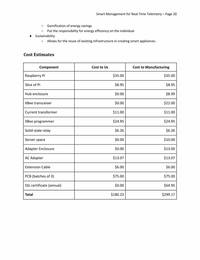
Cost Estimates
Component Cost to Us Cost to Manufacturing
Raspberry Pi $35.00 $35.00
Slice of Pi $8.95 $8.95
Hub enclosure $0.00 $8.99
XBee transceiver $0.00 $22.00
Current transformer $11.00 $11.00
XBee programmer $24.95 $24.95
Solid-state relay $6.26 $6.26
Server space $0.00 $10.00
Adapter Enclosure $0.00 $13.00
AC Adapter $13.07 $13.07
Extension Cable $6.00 $6.00
PCB (batches of 3) $75.00 $75.00
SSL certificate (annual) $0.00 $64.95
Total $180.23 $299.17

Smart Management for Real-Time Telemetry – Page 20
Testing Strategy Test Case Name: Boot Up
Description:
Tests that the adapter can boot up from being unplugged properly.
Setup:
Adapter is unplugged from the wall, has a device plugged into it.
Overall result: Not yet run
Steps Action Expected Result
1 Plug adapter into wall LED turns on
2 Adapter sends a handshake signal to connect with associated hub Hub receives handshake and acknowledges to adapter
3 Sends current state to hub Hub receives state, sends ACK to adapter and forwards information to server
4 Adapter takes current reading and forwards it to the hub Hub acknowledges data and forwards to server
Test Case Name: Current Reading
Description: Tests that the system is properly measuring current and therefore power.
Setup:
Adapter prototype is connected to the wall, a 60W lightbulb and wirlessly connected to a prototyping workstation. Additionally, current transformer's LUT has been setup.
Overall result: Not yet run
Steps Action Expected Result
1 Turn on lightbulb Lightbulb turns on and adapter starts reporting voltage reading
2 Look up reported voltage in the current transformer's LUT LUT reports 500 mA of current
Smart Management for Real-Time Telemetry – Page 21
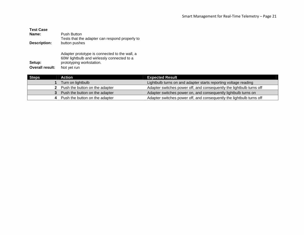
Test Case Name: Push Button
Description:
Tests that the adapter can respond properly to button pushes
Setup:
Adapter prototype is connected to the wall, a 60W lightbulb and wirlessly connected to a prototyping workstation.
Overall result: Not yet run
Steps Action Expected Result
1 Turn on lightbulb Lightbulb turns on and adapter starts reporting voltage reading
2 Push the button on the adapter Adapter switches power off, and consequently the lightbulb turns off
3 Push the button on the adapter Adapter switches power on, and consequently lightbulb turns on
4 Push the button on the adapter Adapter switches power off, and consequently the lightbulb turns off

Smart Management for Real-Time Telemetry – Page 22
Test Case Name: Receive Command Description: Tests that the adapter can receive commands
Setup:
Adapter prototype is connected to the wall, a 60W lightbulb and wirlessly connected to a hub prototype, which is in turn connected to a prototype of the web app
Overall result: Not yet run
Steps Action Expected Result
1 Turn on lightbulb Lightbulb turns on and adapter starts reporting voltage reading
2 Log in to web app Web app says that the adapter is on and drawing power
3 Push the button in the web app to toggle the adapter
Adapter switches power off, and consequently lightbulb turns off. Web app reports that the adapter is no longer drawing power and is turned off.
4 Push the button in the web app to toggle the adapter Adapter switches power on, and consequently lightbulb turns on. Web app reports that the adapter is on and drawing power.
5 Push the button in the web app to toggle the adapter
Adapter switches power off, and consequently lightbulb turns off. Web app reports that the adapter is no longer drawing power and is turned off.
Smart Management for Real-Time Telemetry – Page 23
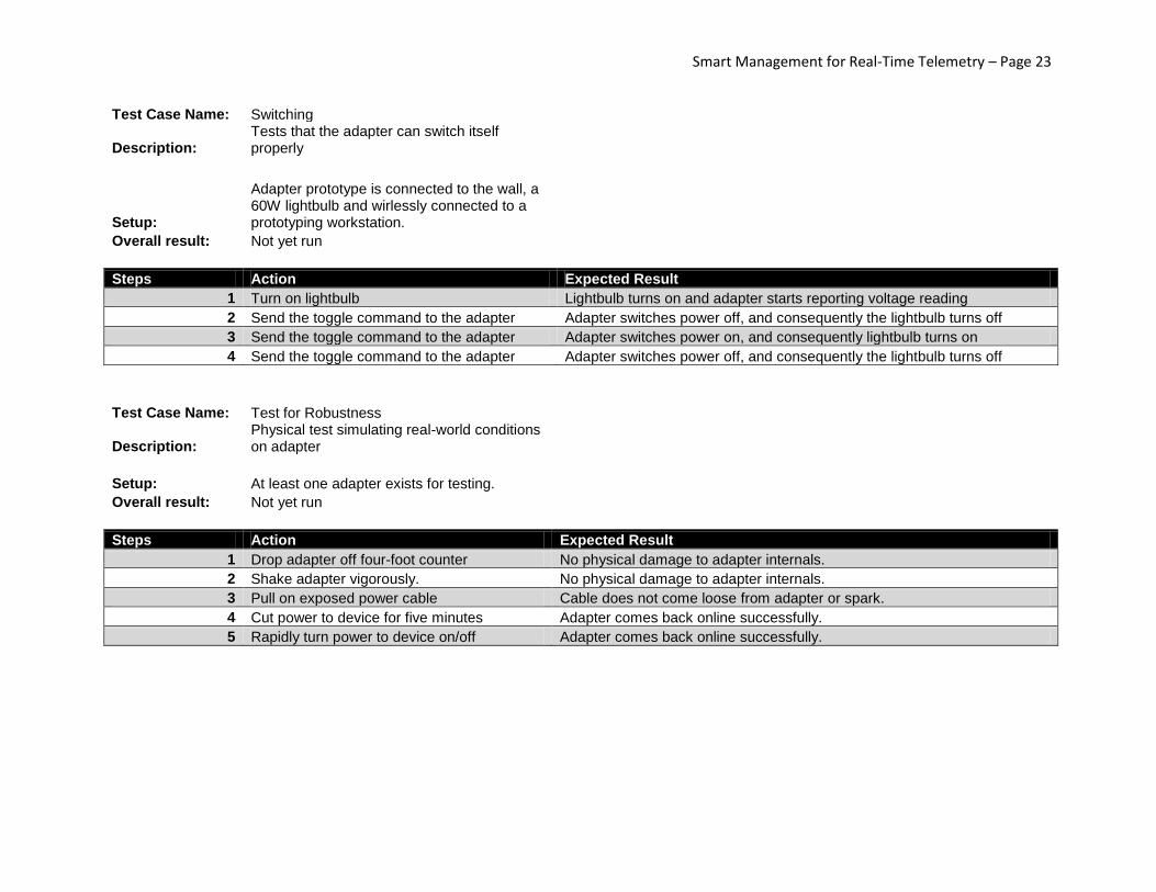
Test Case Name: Switching
Description: Tests that the adapter can switch itself properly
Setup:
Adapter prototype is connected to the wall, a 60W lightbulb and wirlessly connected to a prototyping workstation.
Overall result: Not yet run
Steps Action Expected Result
1 Turn on lightbulb Lightbulb turns on and adapter starts reporting voltage reading
2 Send the toggle command to the adapter Adapter switches power off, and consequently the lightbulb turns off
3 Send the toggle command to the adapter Adapter switches power on, and consequently lightbulb turns on
4 Send the toggle command to the adapter Adapter switches power off, and consequently the lightbulb turns off
Test Case Name: Test for Robustness
Description: Physical test simulating real-world conditions on adapter
Setup: At least one adapter exists for testing. Overall result: Not yet run
Steps Action Expected Result
1 Drop adapter off four-foot counter No physical damage to adapter internals.
2 Shake adapter vigorously. No physical damage to adapter internals.
3 Pull on exposed power cable Cable does not come loose from adapter or spark.
4 Cut power to device for five minutes Adapter comes back online successfully.
5 Rapidly turn power to device on/off Adapter comes back online successfully.

Smart Management for Real-Time Telemetry – Page 24
Test Case Name: Transmit Reading Description: Tests that the adapter can send out data
Setup:
Adapter prototype is connected to the wall, a 60W lightbulb and wirlessly connected to a hub prototype, which is in turn connected to a prototype of the web app
Overall result: Not yet run
Steps Action Expected Result
1 Turn on lightbulb Lightbulb turns on and adapter starts reporting voltage reading
2 Go to power usage reporting page on web app Web app reports using 60W of power

Smart Management for Real-Time Telemetry – Page 25
Test Case Name: Control device Description: Tests the interface for turning on/off a device.
Setup: Have at least one registered user with at least one associated hub and one associated adapter.
Overall result: Not yet run
Steps Action Expected Result
1 User navigates to website interface and logs in Login successful
2 Device readings and account management menu are displayed to user. User clicks on a device to select it.
Device specific options are displayed to user in a submenu.
3 Option to change a device's state is selected.
Confirmation message of the device's state change is displayed to the user. LED on device changes state to indicate device changing state.
4 Server sends T (ID) to hub Hub forwards T to adapter and sends an A T to the server
5 Hub receives updated status from adapter Sends a T (ID) to the server
6 Server sends an A T Hub receives A T
Test Case Name: Create a schedule Description: Tests the interface for adding a scheduled event to a user's device.
Setup: Have at least one registered user with at least one associated hub and one associated adapter.
Overall result: Not yet run
Steps Action Expected Result
1 User navigates to website interface and logs in Login successful
2 Device readings and account management menu are displayed to user. User clicks on a device to select it.
Device specific options are displayed to user in a submenu.
3 Option to schedule an event is selected. Sub-interface for event scheduling pops up
4 User enters date and time, type of event (device on or off) and checks whether the event is recurring or not
Confirmation message is displayed to user. Event icon is placed next to device.
Smart Management for Real-Time Telemetry – Page 26
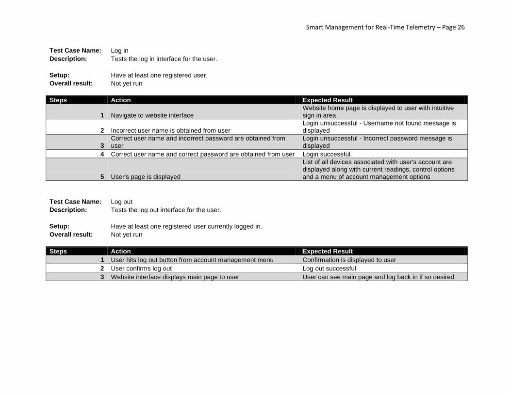
Test Case Name: Log in Description: Tests the log in interface for the user.
Setup: Have at least one registered user. Overall result: Not yet run
Steps Action Expected Result
1 Navigate to website interface Website home page is displayed to user with intuitive sign in area
2 Incorrect user name is obtained from user Login unsuccessful - Username not found message is displayed
3 Correct user name and incorrect password are obtained from user
Login unsuccessful - Incorrect password message is displayed
4 Correct user name and correct password are obtained from user Login successful.
5 User's page is displayed
List of all devices associated with user's account are displayed along with current readings, control options and a menu of account management options
Test Case Name: Log out Description: Tests the log out interface for the user.
Setup: Have at least one registered user currently logged in. Overall result: Not yet run
Steps Action Expected Result
1 User hits log out button from account management menu Confirmation is displayed to user
2 User confirms log out Log out successful
3 Website interface displays main page to user User can see main page and log back in if so desired
Smart Management for Real-Time Telemetry – Page 27
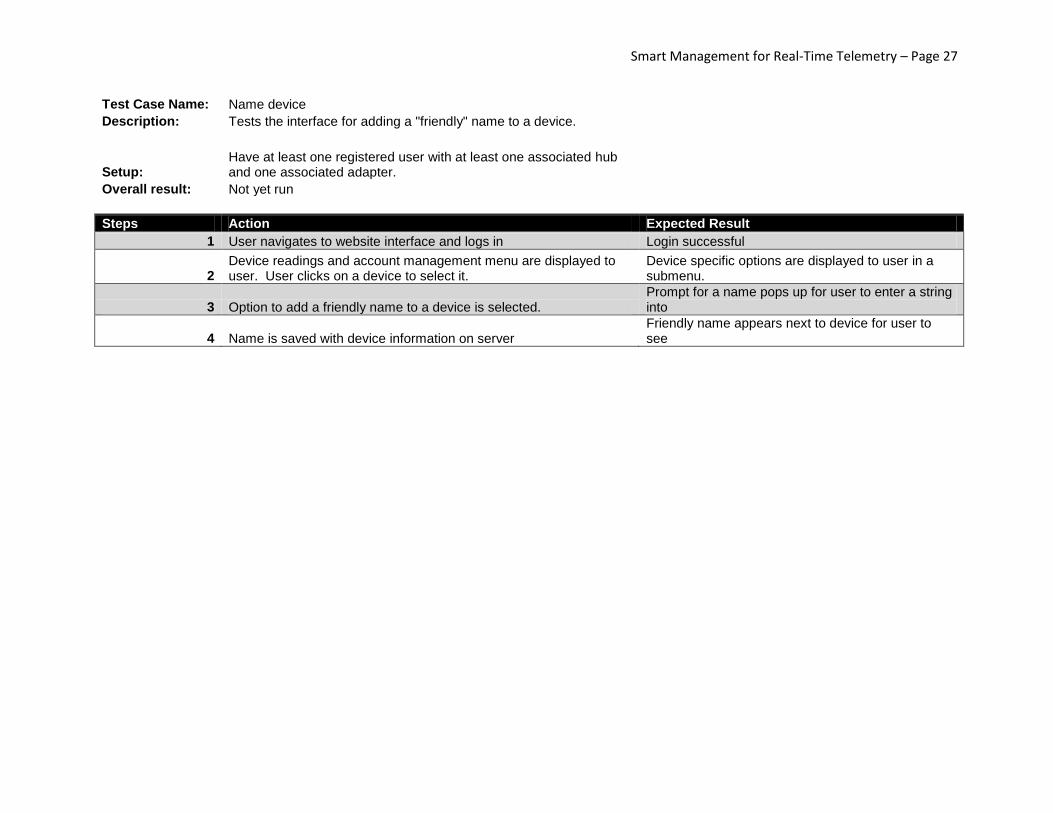
Test Case Name: Name device Description: Tests the interface for adding a "friendly" name to a device.
Setup: Have at least one registered user with at least one associated hub and one associated adapter.
Overall result: Not yet run
Steps Action Expected Result
1 User navigates to website interface and logs in Login successful
2 Device readings and account management menu are displayed to user. User clicks on a device to select it.
Device specific options are displayed to user in a submenu.
3 Option to add a friendly name to a device is selected. Prompt for a name pops up for user to enter a string into
4 Name is saved with device information on server Friendly name appears next to device for user to see

Smart Management for Real-Time Telemetry – Page 28
Test Case Name: Remove device
Description: Tests the interface for adding a device to a user's account.
Setup:
Have at least one registered user with at least one associated hub and one associated adapter.
Overall result: Not yet run
Steps Action Expected Result
1 User navigates to website interface and logs in Login successful
2 Device readings and account management menu are displayed to user. User clicks on a device to select it. Device specific options are displayed to user in a submenu.
3 Option to remove a device is selected. Confirmation window pops up to make sure user wishes to permanently remove device from their account.
4 User confirms device removal Message confirms device has been removed from account.
5 Device is removed from user's list of devices Readings and commands are no longer sent/received from device.
6 Server sends D (ID) to hub Hub receives D (ID)
7 Hub removes device ID from list Hub dissociates with adapter to terminate data and command transmissions
8 Hub sends A D to server Server receives A D
Smart Management for Real-Time Telemetry – Page 29
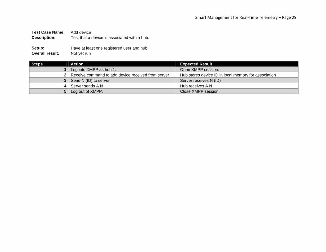
Test Case Name: Add device Description: Test that a device is associated with a hub.
Setup: Have at least one registered user and hub.
Overall result: Not yet run
Steps Action Expected Result
1 Log into XMPP as hub 1. Open XMPP session.
2 Receive command to add device received from server Hub stores device ID in local memory for association
3 Send N (ID) to server Server receives N (ID)
4 Server sends A N Hub receives A N
5 Log out of XMPP. Close XMPP session.
Smart Management for Real-Time Telemetry – Page 30
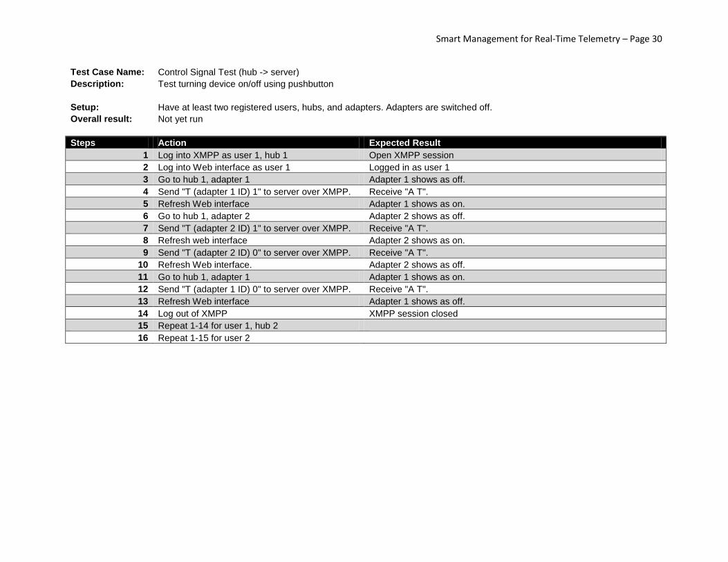
Test Case Name: Control Signal Test (hub -> server)
Description: Test turning device on/off using pushbutton
Setup: Have at least two registered users, hubs, and adapters. Adapters are switched off.
Overall result: Not yet run
Steps Action Expected Result
1 Log into XMPP as user 1, hub 1 Open XMPP session
2 Log into Web interface as user 1 Logged in as user 1
3 Go to hub 1, adapter 1 Adapter 1 shows as off.
4 Send "T (adapter 1 ID) 1" to server over XMPP. Receive "A T".
5 Refresh Web interface Adapter 1 shows as on.
6 Go to hub 1, adapter 2 Adapter 2 shows as off.
7 Send "T (adapter 2 ID) 1" to server over XMPP. Receive "A T".
8 Refresh web interface Adapter 2 shows as on.
9 Send "T (adapter 2 ID) 0" to server over XMPP. Receive "A T".
10 Refresh Web interface. Adapter 2 shows as off.
11 Go to hub 1, adapter 1 Adapter 1 shows as on.
12 Send "T (adapter 1 ID) 0" to server over XMPP. Receive "A T".
13 Refresh Web interface Adapter 1 shows as off.
14 Log out of XMPP XMPP session closed
15 Repeat 1-14 for user 1, hub 2
16 Repeat 1-15 for user 2
Smart Management for Real-Time Telemetry – Page 31
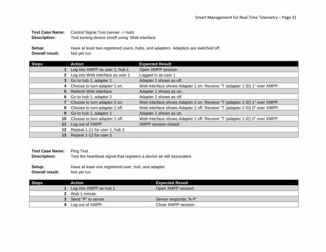
Test Case Name: Control Signal Test (server -> hub)
Description: Test turning device on/off using Web interface
Setup: Have at least two registered users, hubs, and adapters. Adapters are switched off.
Overall result: Not yet run
Steps Action Expected Result
1 Log into XMPP as user 1, hub 1 Open XMPP session
2 Log into Web interface as user 1 Logged in as user 1
3 Go to hub 1, adapter 1 Adapter 1 shows as off.
4 Choose to turn adapter 1 on. Web interface shows Adapter 1 on. Receive "T (adapter 1 ID) 1" over XMPP.
5 Refresh Web interface Adapter 1 shows as on.
6 Go to hub 1, adapter 2 Adapter 2 shows as off.
7 Choose to turn adapter 2 on. Web interface shows Adapter 2 on. Receive "T (adapter 2 ID) 1" over XMPP.
8 Choose to turn adapter 2 off. Web interface shows Adapter 2 off. Receive "T (adapter 2 ID) 0" over XMPP.
9 Go to hub 1, adapter 1 Adapter 1 shows as on.
10 Choose to turn adapter 1 off. Web interface shows Adapter 1 off. Receive "T (adapter 1 ID) 0" over XMPP.
11 Log out of XMPP XMPP session closed
12 Repeat 1-11 for user 1, hub 2
13 Repeat 1-12 for user 2
Test Case Name: Ping Test Description: Test the heartbeat signal that registers a device as still associated.
Setup: Have at least one registered user, hub, and adapter.
Overall result: Not yet run
Steps Action Expected Result
1 Log into XMPP as hub 1. Open XMPP session.
2 Wait 1 minute.
3 Send "P" to server. Server responds "A P".
4 Log out of XMPP. Close XMPP session.
Smart Management for Real-Time Telemetry – Page 32
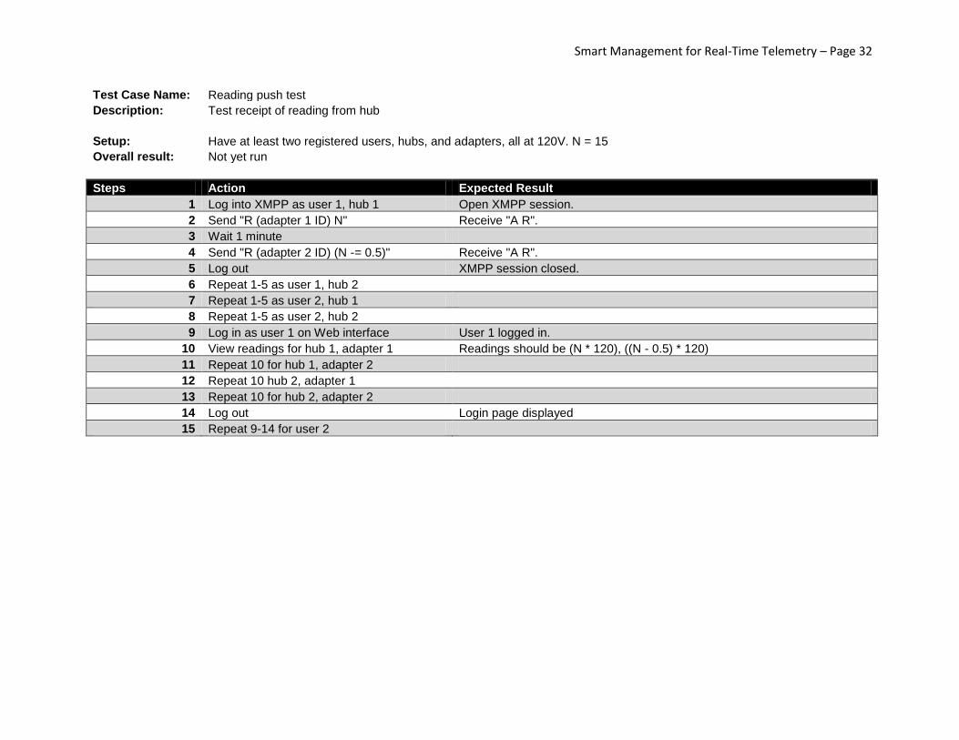
Test Case Name: Reading push test Description: Test receipt of reading from hub
Setup: Have at least two registered users, hubs, and adapters, all at 120V. N = 15
Overall result: Not yet run
Steps Action Expected Result
1 Log into XMPP as user 1, hub 1 Open XMPP session.
2 Send "R (adapter 1 ID) N" Receive "A R".
3 Wait 1 minute
4 Send "R (adapter 2 ID) (N -= 0.5)" Receive "A R".
5 Log out XMPP session closed.
6 Repeat 1-5 as user 1, hub 2
7 Repeat 1-5 as user 2, hub 1
8 Repeat 1-5 as user 2, hub 2
9 Log in as user 1 on Web interface User 1 logged in.
10 View readings for hub 1, adapter 1 Readings should be (N * 120), ((N - 0.5) * 120)
11 Repeat 10 for hub 1, adapter 2
12 Repeat 10 hub 2, adapter 1
13 Repeat 10 for hub 2, adapter 2
14 Log out Login page displayed
15 Repeat 9-14 for user 2
Smart Management for Real-Time Telemetry – Page 33
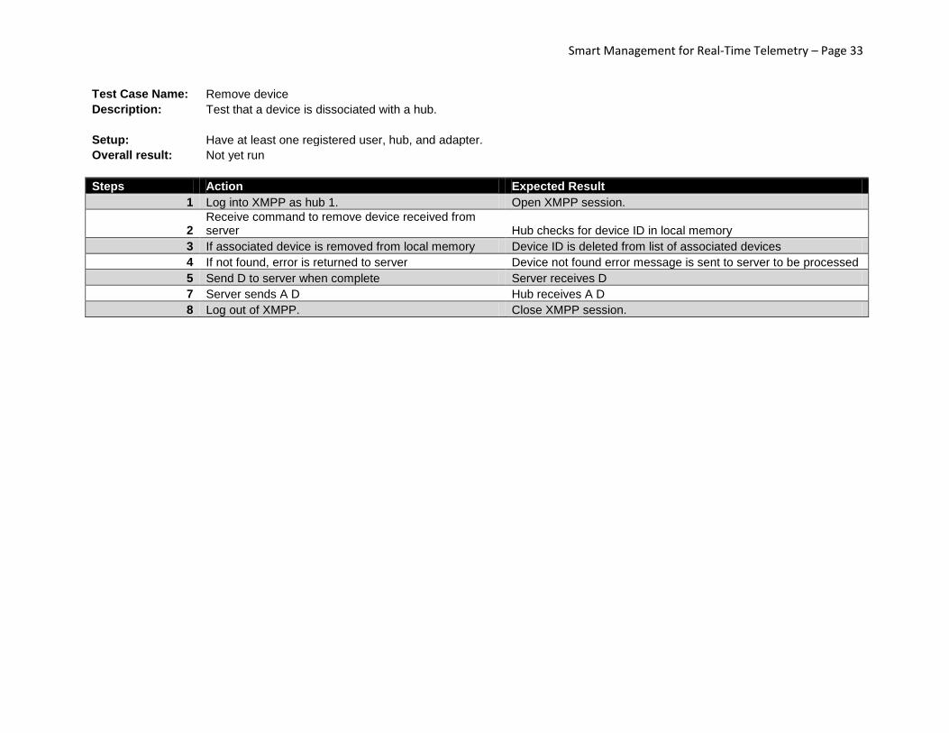
Test Case Name: Remove device Description: Test that a device is dissociated with a hub.
Setup: Have at least one registered user, hub, and adapter.
Overall result: Not yet run
Steps Action Expected Result
1 Log into XMPP as hub 1. Open XMPP session.
2 Receive command to remove device received from server Hub checks for device ID in local memory
3 If associated device is removed from local memory Device ID is deleted from list of associated devices
4 If not found, error is returned to server Device not found error message is sent to server to be processed
5 Send D to server when complete Server receives D
7 Server sends A D Hub receives A D
8 Log out of XMPP. Close XMPP session.

Smart Management for Real-Time Telemetry – Page 34
Test Case Name: Scheduler Test Description: Test turning devices on/off from scheduler
Setup: Have at least two registered users, hubs, and adapters.
Overall result: Not yet run
Steps Action Expected Result
1 Log in as user 1 User 1 logged in
2 Select hub 1 Hub 1 details shown
3 Select adapter 1 Adapter 1 details shown
4 Add schedule to turn on 5 minutes in future Confirmation message displayed
5 Add schedule to turn off 6 minutes in future Confirmation message displayed
6 Select adapter 2 Adapter 2 details shown
7 Repeat 4-5 for adapter 2
8 Select hub 2 Hub 2 details shown
9 Repeat 3-7 for hub 2
10 Log out of user 1 Login page displayed
11 Log in as user 2 User 2 logged in
12 Repeat steps 2-9 as user 2
13 Wait 5 minutes after each entry created Each device should turn on independently (not at the same time)
14 Wait 1 minute after devices turn on Each device should turn off independently
15 Disable scheduler once complete Scheduled tasks go inactive once events complete
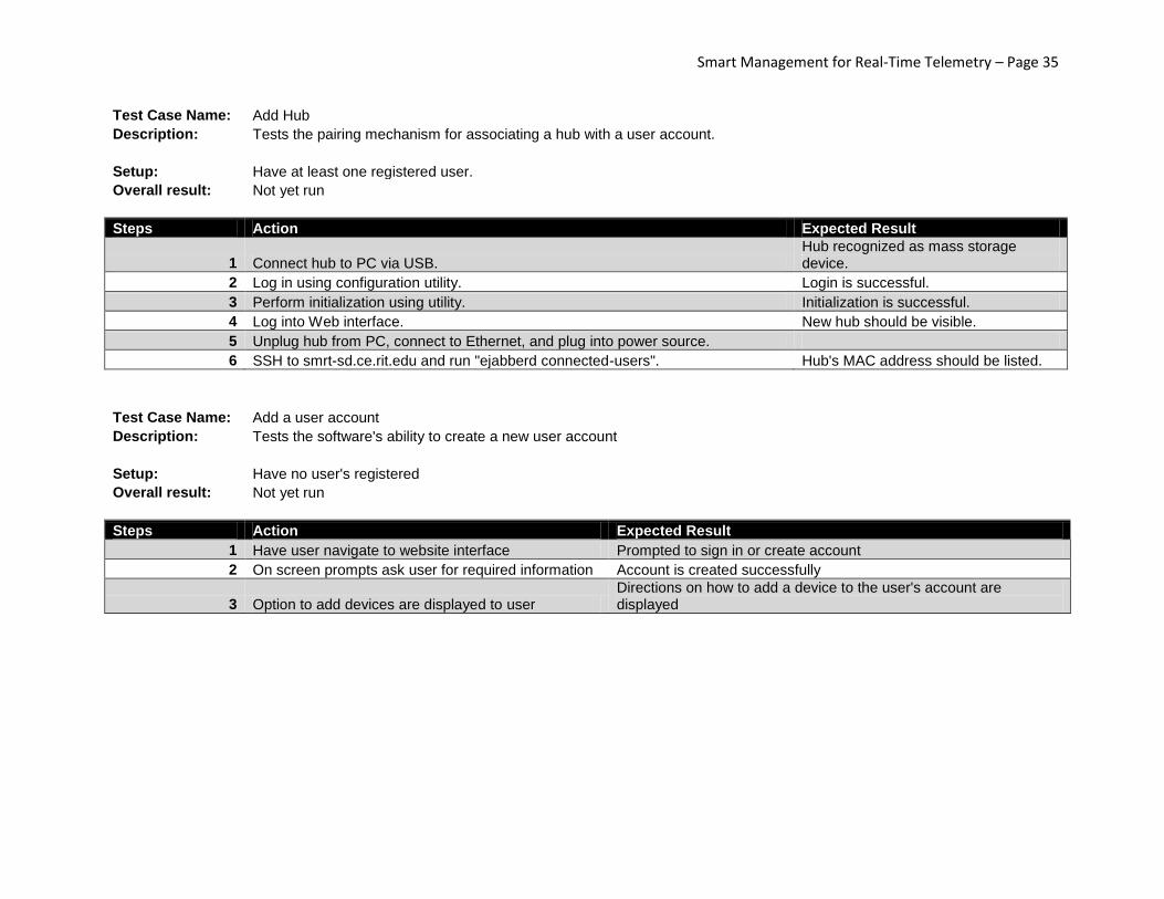
Smart Management for Real-Time Telemetry – Page 35
Test Case Name: Add Hub Description: Tests the pairing mechanism for associating a hub with a user account.
Setup: Have at least one registered user.
Overall result: Not yet run
Steps Action Expected Result
1 Connect hub to PC via USB. Hub recognized as mass storage device.
2 Log in using configuration utility. Login is successful.
3 Perform initialization using utility. Initialization is successful.
4 Log into Web interface. New hub should be visible.
5 Unplug hub from PC, connect to Ethernet, and plug into power source.
6 SSH to smrt-sd.ce.rit.edu and run "ejabberd connected-users". Hub's MAC address should be listed.
Test Case Name: Add a user account
Description: Tests the software's ability to create a new user account
Setup: Have no user's registered
Overall result: Not yet run
Steps Action Expected Result
1 Have user navigate to website interface Prompted to sign in or create account
2 On screen prompts ask user for required information Account is created successfully
3 Option to add devices are displayed to user Directions on how to add a device to the user's account are displayed
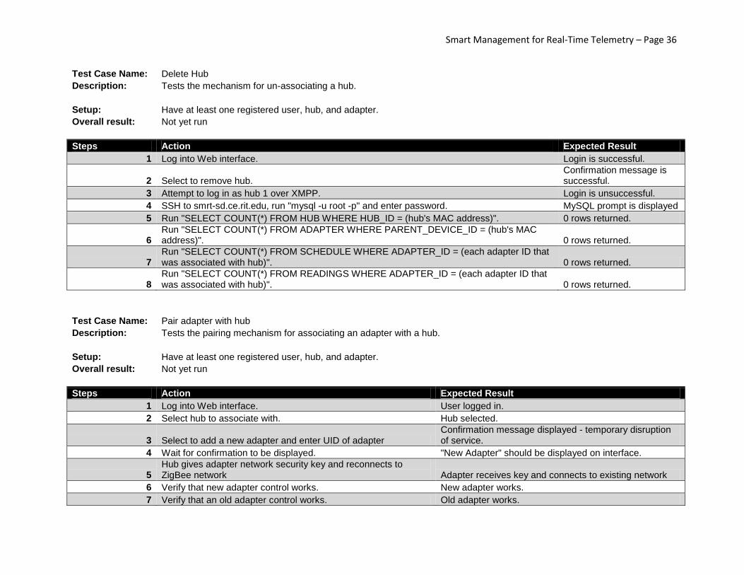
Smart Management for Real-Time Telemetry – Page 36
Test Case Name: Delete Hub Description: Tests the mechanism for un-associating a hub.
Setup: Have at least one registered user, hub, and adapter.
Overall result: Not yet run
Steps Action Expected Result
1 Log into Web interface. Login is successful.
2 Select to remove hub. Confirmation message is successful.
3 Attempt to log in as hub 1 over XMPP. Login is unsuccessful.
4 SSH to smrt-sd.ce.rit.edu, run "mysql -u root -p" and enter password. MySQL prompt is displayed
5 Run "SELECT COUNT(*) FROM HUB WHERE HUB_ID = (hub's MAC address)". 0 rows returned.
6 Run "SELECT COUNT(*) FROM ADAPTER WHERE PARENT_DEVICE_ID = (hub's MAC address)". 0 rows returned.
7 Run "SELECT COUNT(*) FROM SCHEDULE WHERE ADAPTER_ID = (each adapter ID that was associated with hub)". 0 rows returned.
8 Run "SELECT COUNT(*) FROM READINGS WHERE ADAPTER_ID = (each adapter ID that was associated with hub)". 0 rows returned.
Test Case Name: Pair adapter with hub
Description: Tests the pairing mechanism for associating an adapter with a hub.
Setup: Have at least one registered user, hub, and adapter.
Overall result: Not yet run
Steps Action Expected Result
1 Log into Web interface. User logged in.
2 Select hub to associate with. Hub selected.
3 Select to add a new adapter and enter UID of adapter Confirmation message displayed - temporary disruption of service.
4 Wait for confirmation to be displayed. "New Adapter" should be displayed on interface.
5 Hub gives adapter network security key and reconnects to ZigBee network Adapter receives key and connects to existing network
6 Verify that new adapter control works. New adapter works.
7 Verify that an old adapter control works. Old adapter works.
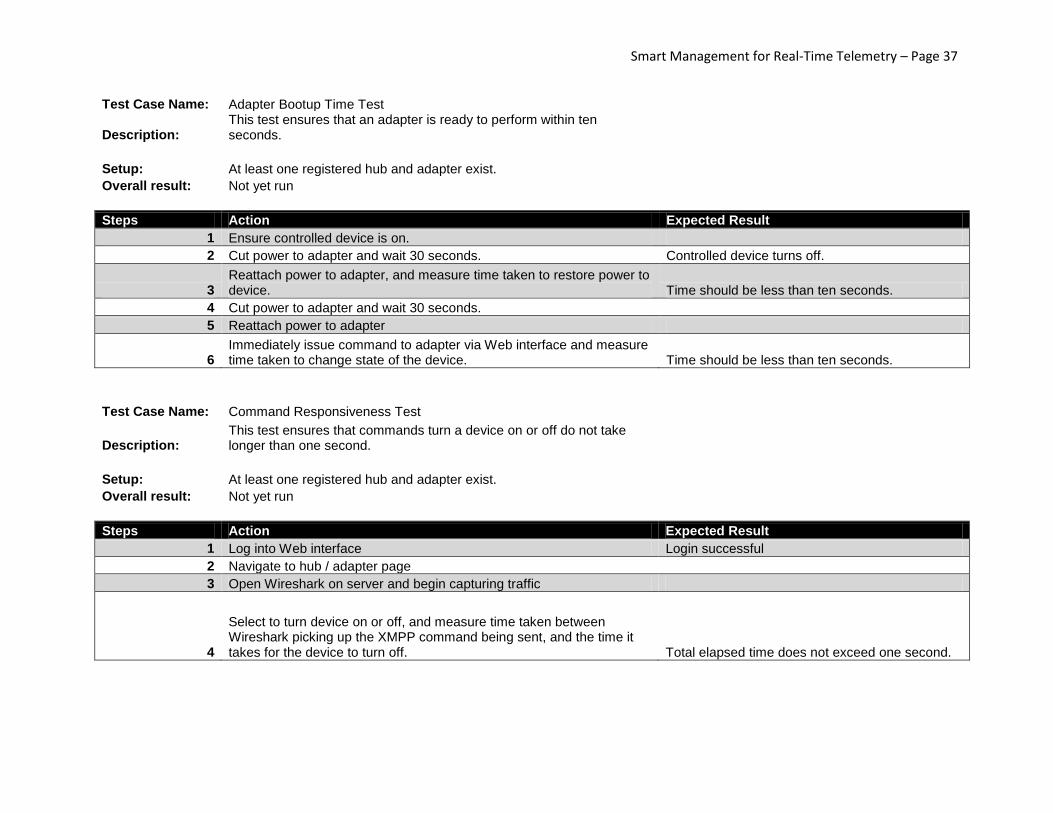
Smart Management for Real-Time Telemetry – Page 37
Test Case Name: Adapter Bootup Time Test
Description: This test ensures that an adapter is ready to perform within ten seconds.
Setup: At least one registered hub and adapter exist. Overall result: Not yet run
Steps Action Expected Result
1 Ensure controlled device is on.
2 Cut power to adapter and wait 30 seconds. Controlled device turns off.
3 Reattach power to adapter, and measure time taken to restore power to device. Time should be less than ten seconds.
4 Cut power to adapter and wait 30 seconds.
5 Reattach power to adapter
6 Immediately issue command to adapter via Web interface and measure time taken to change state of the device. Time should be less than ten seconds.
Test Case Name: Command Responsiveness Test
Description: This test ensures that commands turn a device on or off do not take longer than one second.
Setup: At least one registered hub and adapter exist. Overall result: Not yet run
Steps Action Expected Result
1 Log into Web interface Login successful
2 Navigate to hub / adapter page
3 Open Wireshark on server and begin capturing traffic
4
Select to turn device on or off, and measure time taken between Wireshark picking up the XMPP command being sent, and the time it takes for the device to turn off. Total elapsed time does not exceed one second.
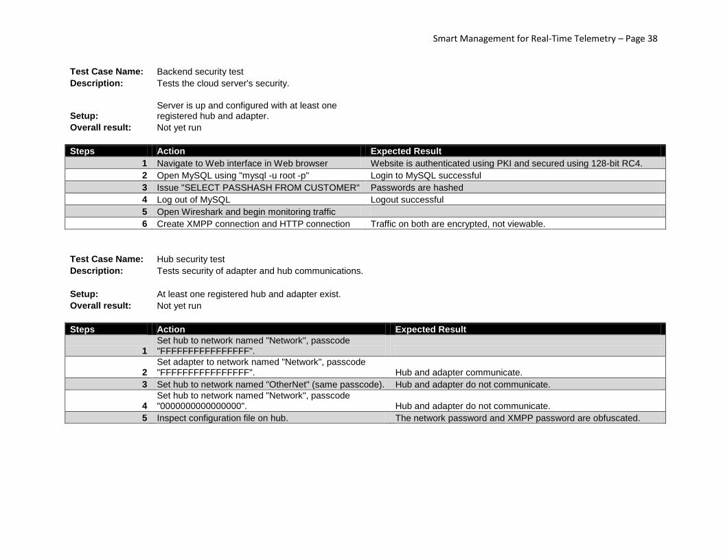
Smart Management for Real-Time Telemetry – Page 38
Test Case Name: Backend security test Description: Tests the cloud server's security.
Setup:
Server is up and configured with at least one registered hub and adapter.
Overall result: Not yet run
Steps Action Expected Result
1 Navigate to Web interface in Web browser Website is authenticated using PKI and secured using 128-bit RC4.
2 Open MySQL using "mysql -u root -p" Login to MySQL successful
3 Issue "SELECT PASSHASH FROM CUSTOMER" Passwords are hashed
4 Log out of MySQL Logout successful
5 Open Wireshark and begin monitoring traffic
6 Create XMPP connection and HTTP connection Traffic on both are encrypted, not viewable.
Test Case Name: Hub security test Description: Tests security of adapter and hub communications.
Setup: At least one registered hub and adapter exist. Overall result: Not yet run
Steps Action Expected Result
1 Set hub to network named "Network", passcode "FFFFFFFFFFFFFFFF".
2 Set adapter to network named "Network", passcode "FFFFFFFFFFFFFFFF". Hub and adapter communicate.
3 Set hub to network named "OtherNet" (same passcode). Hub and adapter do not communicate.
4 Set hub to network named "Network", passcode "0000000000000000". Hub and adapter do not communicate.
5 Inspect configuration file on hub. The network password and XMPP password are obfuscated.

Smart Management for Real-Time Telemetry – Page 39
Risks ● Hardest Part: Networking (No background)
○ ZigBee network failure
■ Hub queues up readings and commands so that they can be passed when the
network comes back online.
○ Internet connection failure
■ XMPP heartbeat signal determines the presence of connectivity at both the server
and the hub.
● Heat output of solid-state relay must not cause excessively high temperatures
○ A heatsink will dissipate excess heat.
● Encasing should not physically break when dropped, and should protect internal components
○ A PCB will be used to provide sturdy mounting for components.
○ The casing should be electrically isolated from stray wall current, to protect the user.
○ A repurposed laptop power adapter enclosure will be used, as it is pre-engineered for
the same types of operating conditions.
● Power failure should not cause a device to stop working
○ Configuration data should be stored in a non-volatile manner.
○ AC-DC converter will be fused.
● Security
○ End-to-end encryption on ZigBee LAN (128-bit AES)
○ End-to-end encryption between Tomcat and Web browser (128-bit RC4)
○ Authentication between Tomcat and browser performed using PKI (CACert, free)
○ Authentication of hub uses hub’s MAC address
○ Authentication of device uses 64-bit UID of XBee
Smart Management for Real-Time Telemetry – Page 40
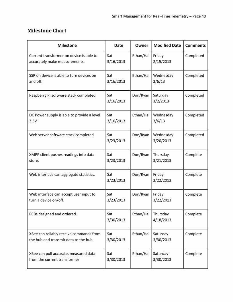
Milestone Chart
Milestone Date Owner Modified Date Comments
Current transformer on device is able to
accurately make measurements.
Sat
3/16/2013
Ethan/Hal Friday
2/15/2013
Completed
SSR on device is able to turn devices on
and off.
Sat
3/16/2013
Ethan/Hal Wednesday
3/6/13
Completed
Raspberry Pi software stack completed Sat
3/16/2013
Don/Ryan Saturday
3/2/2013
Completed
DC Power supply is able to provide a level
3.3V
Sat
3/16/2013
Ethan/Hal Wednesday
3/6/13
Completed
Web server software stack completed Sat
3/23/2013
Don/Ryan Wednesday
3/20/2013
Completed
XMPP client pushes readings into data
store.
Sat
3/23/2013
Don/Ryan Thursday
3/21/2013
Complete
Web interface can aggregate statistics. Sat
3/23/2013
Don/Ryan Friday
3/22/2013
Complete
Web interface can accept user input to
turn a device on/off.
Sat
3/23/2013
Don/Ryan Friday
3/22/2013
Complete
PCBs designed and ordered. Sat
3/30/2013
Ethan/Hal Thursday
4/18/2013
Complete
XBee can reliably receive commands from
the hub and transmit data to the hub
Sat
3/30/2013
Ethan/Hal Saturday
3/30/2013
Complete
XBee can pull accurate, measured data
from the current transformer
Sat
3/30/2013
Ethan/Hal Saturday
3/30/2013
Complete

Smart Management for Real-Time Telemetry – Page 41
Hub can reliably receive and transmit
commands over the ZigBee network.
Sat
4/6/2013
Don/Ryan Friday
4/5/2013
Complete
Hub can reliably receive and transmit
commands from the Web.
Sat
4/6/2013
Don/Ryan Tuesday
4/9/2013
Complete
Website update. Tue
4/9/2013
Don/Ryan Monday
4/18/2013
Complete
Full integration of components into brick-
on-a-leash.
Sat
4/20/2013
Ethan/Hal Sunday
4/28/2013
Complete
Android interface pushes user commands
to server
Sat
4/20/2013
Ethan/Hal Sunday
4/28/2013
At Risk
Android interface accepts data from server Sat
4/20/2013
Ethan/Hal Sunday
4/28/2013
At Risk
Draft of final project poster and report. Thu
4/25/2013
Everyone Wednesday
4/24/2013
Complete
Finished website. Tue
4/30/2013
Don/Ryan Sunday
4/28/2013
Complete
Final project poster and report. Tue
4/30/2013
Everyone Sunday
4/28/2013
Complete

Smart Management for Real-Time Telemetry – Page 39
Gantt Chart
Mon Mar 4
ISO WEEK NUM W1 W2 W3 W4 W5 W6 W7 W8 W9 W10 W11
MONTH MAR APR MAY (MON)DAY 04 11 18 25 01 08 15 22 29 06 13
Hardware
SSR Stops Flow DONE
Current Transforms Measures DONE
DC Power Supply Yields 3.3V DONE
XBee Reads Voltage
DONE
XBee Receives & Acts Upon Command
DONE
XBee Transmits Data To Hub
DONE
PCBs Designed and Ordered
DONE
Full Integration of Parts
DONE
Emergency Buffer Time
Software
Software Stack for Raspberry Pi DONE
Web Server Software Stack
DONE
XMPP Client
DONE
Web Interface Shows Statistics
DONE
Web Interface Accepts User Input
DONE
Hub Communicates to XBee Network
DONE
Hub Communicates with Web DONE
Hub Sends/Receives Commands
DONE
Android Interface Pushes Data
AT RISK
Android Interface Receives Data
AT RISK
Website
DONE
Project Report and Poster
DONE
Emergency Buffer Time
Smart Management for Real-Time Telemetry – Page 39
Perspective Overall, the foundations backing the final project turned out to be solid. Areas in which the team had a
solid foundation tended to produce the best systems; however, areas in which the team had little to no
experience tended to be prone to errors, primarily in the design of the system before its assembly.
The software stack running on the cloud server was implemented mostly in the way planned. The only
deviation from the original design was that a Java-based module for authenticating ejabberd clients
against MySQL had to be rewritten in Python, due to an incompatibility between the way Java and
Erlang process the standard input and output streams. This substitution did not compromise the system
or cut corners in any way, and was purely a design oversight.
Programming for the Raspberry Pi turned out to be slightly more difficult than expected. For instance,
setting up the Raspberry Pi to allow use of its serial port (for use with the XBee modem) requires
modification of kernel configuration files. The XBee API, which claims to be fully compatible with Linux,
has its serial port name hard-coded to “/dev/ttyUSB0”, even though some systems such as the Pi use a
different /dev entry for the serial port. It was determined in programming for the serial port that
multithreading was not possible with two threads using the serial port, so the original concept to run
two independent daemons for taking measurements and processing commands was scrapped in favor
of a single-threaded approach for both, which on the bright side ended up giving a performance benefit.
Working with the XBee modems was unfamiliar at first. Configuring the radio interface on all units took
longer than expected, as the radios we were provided with had previous configuration data on them
that we were not aware of – resetting the radios to factory defaults made them work as expected. The
team ended up encountering bandwidth issues transmitting large number of readings, due to improper
assumptions concerning the XBee’s buffer sizes. This was worked around by using the cyclic sleep timer
built into the XBee to only transmit in short bursts, rather than continuously.
The printed circuit boards proved to be the biggest problem for the team, as no members were familiar
with PCB design. Our faculty contact was unavailable until after our scheduled milestone completion
date to advise in design, putting back both its construction and testing. Integration of parts to the PCB
showed the team’s shortcomings: the power supply ended up being mounted upside-down, and the
pitch of several parts was too wide to fit in the holes that were ordered. The end result was that some
components had to “hang out” off the PCB itself, and instead were held together with solder and heat-
shrink tubing. Due to this, the device enclosures that we selected were no longer sufficient to house the
devices, which the team mitigated by using cardboard boxes as enclosures.
Finally, full integration testing of the interfaces to the platform came too late in the project – such tasks
should have been scheduled earlier, to prevent schedule overruns and last-minute fixes. Creation of a
lookup table, for instance, came very late in the project, and while effective, was performed at a break-
neck pace.