smart grid and power electronics - why do we need high …
TRANSCRIPT
© ABB Group July 20, 2010 | Slide 1
Smart Grid and Power Electronics - Why Do We Need High MW Electronics
Le Tang, ABB Inc.
High MW Electronics – Industry Roadmap Meeting at NIST, Dec. 11, 2009

© ABB Group July 20, 2010 | Slide 2
Smart electricity – efficient power for a sustainable world
A smart grid is the evolved system that manages the electricity demand
in asustainable, reliable and economic manner
built onadvanced infrastructure
and tuned to facilitatethe integration of behavior of all involved

© ABB Group July 20, 2010 | Slide 3
The visionary smart gridSumming up the major requirements
Capacity
Reliability
Efficiency
Sustainability
Upgrade/install capacity economicallyProvide additional infrastructure (e-cars)
Stabilize the system and avoid outagesProvide high quality power all the time
Improve efficiency of power generationReduce losses in transport and consumption
Connect renewable energy to the gridManage intermittent generation

© ABB Group July 20, 2010 | Slide 4
Smart Grid RequirementsIntegration from supply to demand – 4 pillars
Demand response
Integration of electric vehicles
Integration of
renewables Reliability and
Efficiency
Smart Grid is more than only smart meters.Smart Grid includes both transmission and distribution.Smart Grid includes both automation/IT and power devices.

© ABB Group July 20, 2010 | Slide 5
Power Electronics in Smart Grids A key technology in at least 3 of the 4 pillars
Integration of electric vehicles
Reliability and
Efficiency
Integration of
renewables
Demand response

© ABB Group July 20, 2010 | Slide 6
Power Electronics in Smart Grids Integration of renewables
Solar converters
Wind turbine converters
At wind farm point of connection to grid:SVC/STATCOM for grid code compliance
Synchronous condenserEnergy storage e.g. Dynapow for improving stability and
decrease power fluctuations
Integration of renewables
HVDC for offshore wind park connection
Ocean energy harvestingconverters
Residential Distributed Generation (e.g small wind
turbines, solar panel)
Micro-hydro power converters
© ABB Group July 20, 2010 | Slide 7
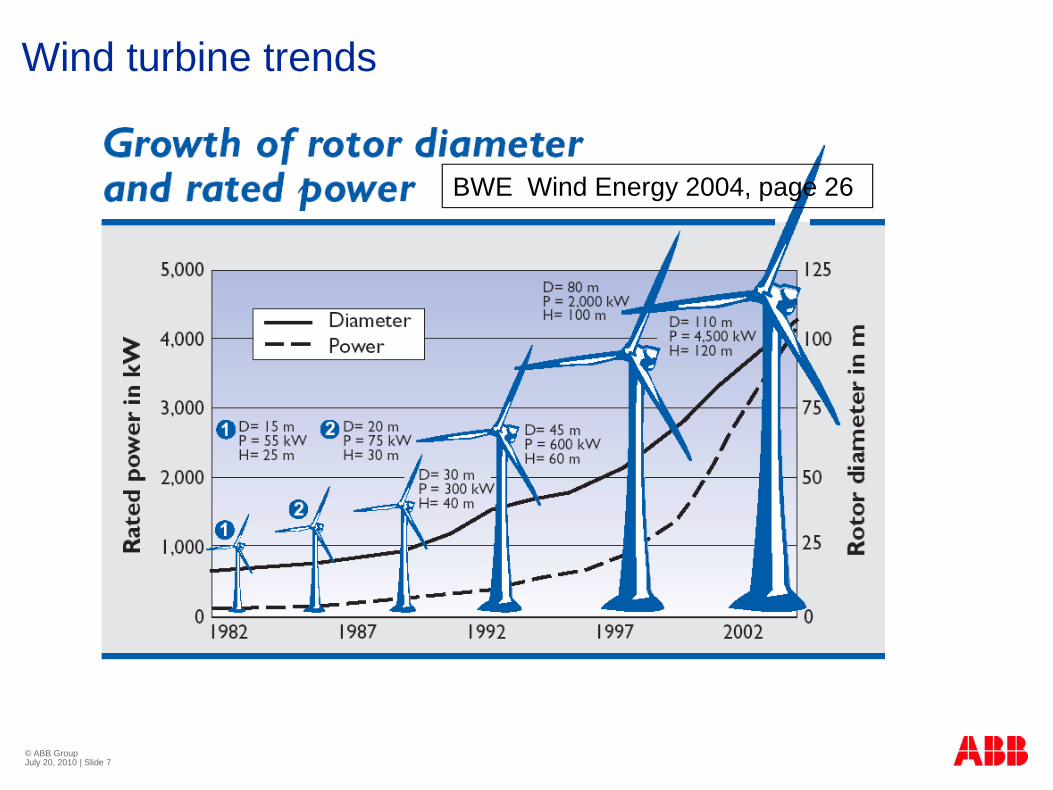
Wind turbine trends
BWE Wind Energy 2004, page 26

© ABB Group July 20, 2010 | Slide 8
Wind Turbine Converters
Fit inside the mast of the turbine
Convert the generated power to the desired frequency and voltage
Help support weak grid by supplying or absorbing reactive power
© ABB Group July 20, 2010 | Slide 9
P
PPQ Q
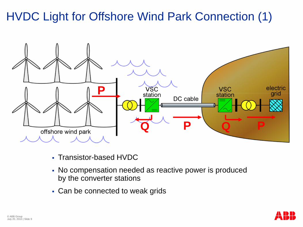
Transistor-based HVDC
No compensation needed as reactive power is produced by the converter stations
Can be connected to weak grids
HVDC Light for Offshore Wind Park Connection (1)
© ABB Group July 20, 2010 | Slide 10
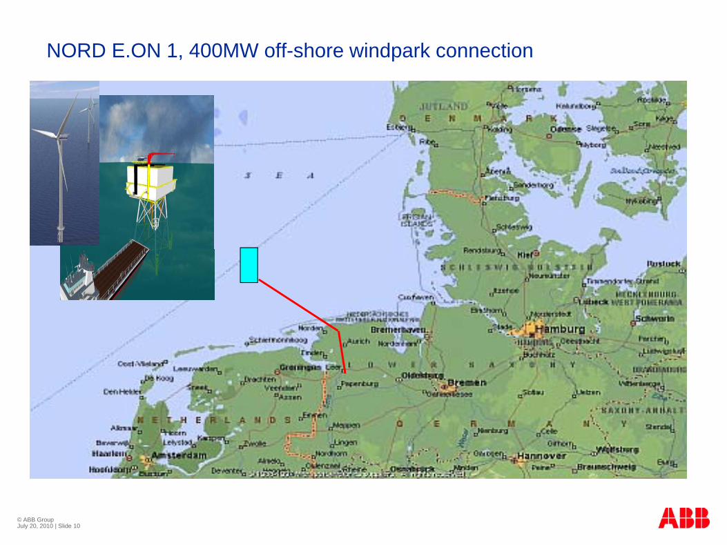
NORD E.ON 1, 400MW off-shore windpark connection

© ABB Group July 20, 2010 | Slide 11
NORD E.ON 1Customer
E.ON Netz GmbH, Germany
Scope
400 MW HVDC Light System
Two HVDC Light converter stations
DC Cable system
DC cable submarine to onshore connection (2x128km)
DC cable on land (2x75km)
200 MW Submarine AC cable 170kV (1x1200 m)
Fiber optic cable (203 km)
170 kV GIS on platformOffshore platform structure - jacket and topside
… and all Auxiliary Systems needed to operate and maintain the Offshore station.
Sea Water System, HVAC, Dieselgenerators, Fire Protection, etc

© ABB Group July 20, 2010 | Slide 12
Layout platform
GIS
Future shunt reactor(s) max
40 MVar

© ABB Group July 20, 2010 | Slide 13
Diele1Offshore1
HVDC Light Cable +150 kV
HVDC Light Cable -150 kV
Phase Reactor
AC Filter
Power Transformer D
C C
apac
itor
Converter Valve
GIS
Scope
SLD March 2008JL
AC B
reak
er +
pr
eins
ert.
Res
isto
r
DC
Cho
pper
Bard platform
1 km
? km OWP Future 1
OWP Future 2? km
Future shunt reactor(s) max
40 MVar
Future HVDC Transmission Link 1
Future HVDC Transmission Link 2
400 kV
On-shore converter rating based on Grid Code:
Overview, 400 MW HVDC Light System Nord E.ON 1
Offshore rating conditions
No tap-changer
Wind park Q
Cable grid Q
Fault ride through
Future scenarios(Pre-Eng. ABB)

© ABB Group July 20, 2010 | Slide 14
Integrating renewable powerIntermittent power generation
Electricity from wind and solar plants is intermittentSpinning reserves between 5 and 18 percent of installed wind energy are required1
Plant interconnections and a wide range of storage technologies could reduce the need for reserves
The future electrical system must be able to cope with these challenges
CapacityReliabilityEfficiency
Sustainability
1 Wind impact on power system, Bremen 2009

© ABB Group July 20, 2010 | Slide 15
Optimizing supply and demandAdjusting the energy mix
Power consumption varies over the year and during the day and night
To satisfy demand all the time reserve capacity is required. For environmental reasons reserves should be minimal.
The challenge of reliability grows with more intermittent renewable energy
A wide range of electrical storage technologies could mitigate the problem
The future electrical system must provide optimal solutions
CapacityReliabilityEfficiency
Sustainability GW
2
4
6
8
00 h 12 h 00 h 12 h 00 h
Demand
Mix of different energy sources for base load and peak load
© ABB Group July 20, 2010 | Slide 16
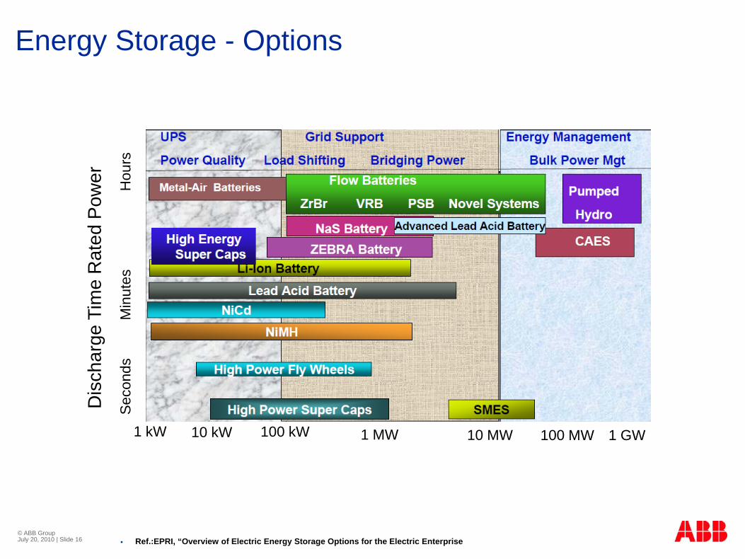
Energy Storage - Options
Ref.:EPRI, “Overview of Electric Energy Storage Options for the Electric Enterprise
1 kW 10 kW 100 kW 1 MW 100 MW 1 GW10 MW
Dis
char
ge T
ime
Rat
ed P
ower
Sec
onds
Min
utes
Hou
rs

© ABB Group July 20, 2010 | Slide 17
Power Electronics in Energy Storage – Examples
Simplified view of a flywheel energy storage system Components of a typical SMES system
Ref:
PAULO F. RIBEIRO, BRIAN K. JOHNSON, MARIESA L. CROW, AYSEN ARSOY, “Energy Storage Systems for Advanced Power Applications”
Edward Furlong, Marco Piemontesi, Prasad P, Sukumar De, “Advances in energy storage techniques for critical power systems”.
Fast charging system for a car battery

© ABB Group July 20, 2010 | Slide 18
Power Electronics in Energy Storage – Regensys Battery Energy Storage System (BESS)
System view of Regensys BESS plant
Main elements of the Regenesys system

© ABB Group July 20, 2010 | Slide 19
StorageProject example: Battery Energy Storage for GVEA
Golden Valley Electric Association BESS Project
40 MW Rating
10 MWH Battery Capacity

© ABB Group July 20, 2010 | Slide 20
ABB FACTS: Dynamic Energy Storage
Energy storage connected on DC-side of converter (SVC Light)
Size depends on power level and duration
Charge energy equal to load energy
Focus on “dynamic”, manages:
High number charge and discharge cycles
High Power at medium duration
Chosen high performance battery as energy storage
© ABB Group July 20, 2010 | Slide 21
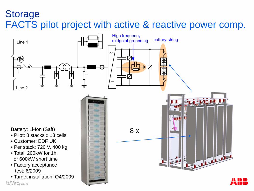
StorageFACTS pilot project with active & reactive power comp.
Battery: Li-Ion (Saft)• Pilot: 8 stacks x 13 cells• Customer: EDF UK• Per stack: 720 V, 400 kg• Total: 200kW for 1h, or 600kW short time
• Factory acceptance test: 6/2009
• Target installation: Q4/2009
8 x

© ABB Group July 20, 2010 | Slide 22
Installation of Field Demonstrator ABB UK has a contract on an installation of afield demonstrator installation in distribution network
Customer is EDF Energy, UK
11 kV Energy Storage and Voltage Control
Data:
System Voltage: 11 kV ±6%
Reactive Power: 600 kVAr inductiveto 600 kVAr capacitive
Active Power: 600 kW (short time),200 kW during 1 hour
© ABB Group July 20, 2010 | Slide 23
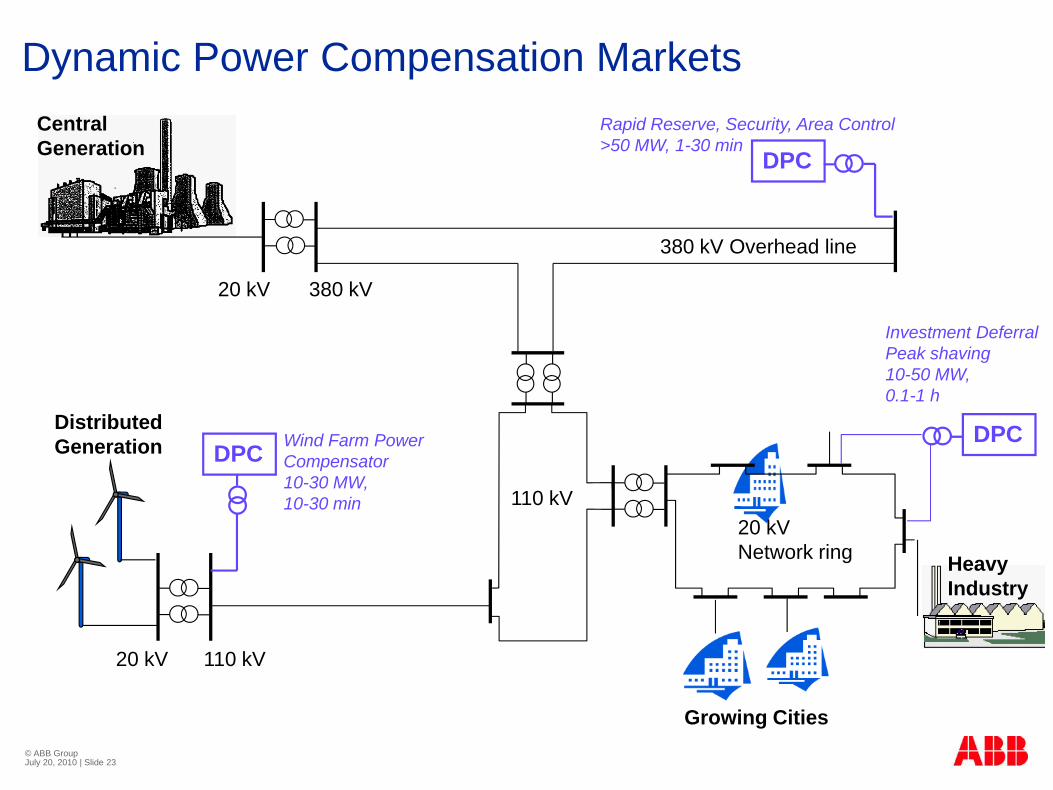
Dynamic Power Compensation Markets
380 kV
110 kV20 kVNetwork ring
20 kV
HeavyIndustry
CentralGeneration
20 kV 110 kV
DistributedGeneration
380 kV Overhead line
DPCRapid Reserve, Security, Area Control>50 MW, 1-30 min
DPC Wind Farm PowerCompensator10-30 MW, 10-30 min
DPC
Investment DeferralPeak shaving10-50 MW, 0.1-1 h
Growing Cities
© ABB Group July 20, 2010 | Slide 24
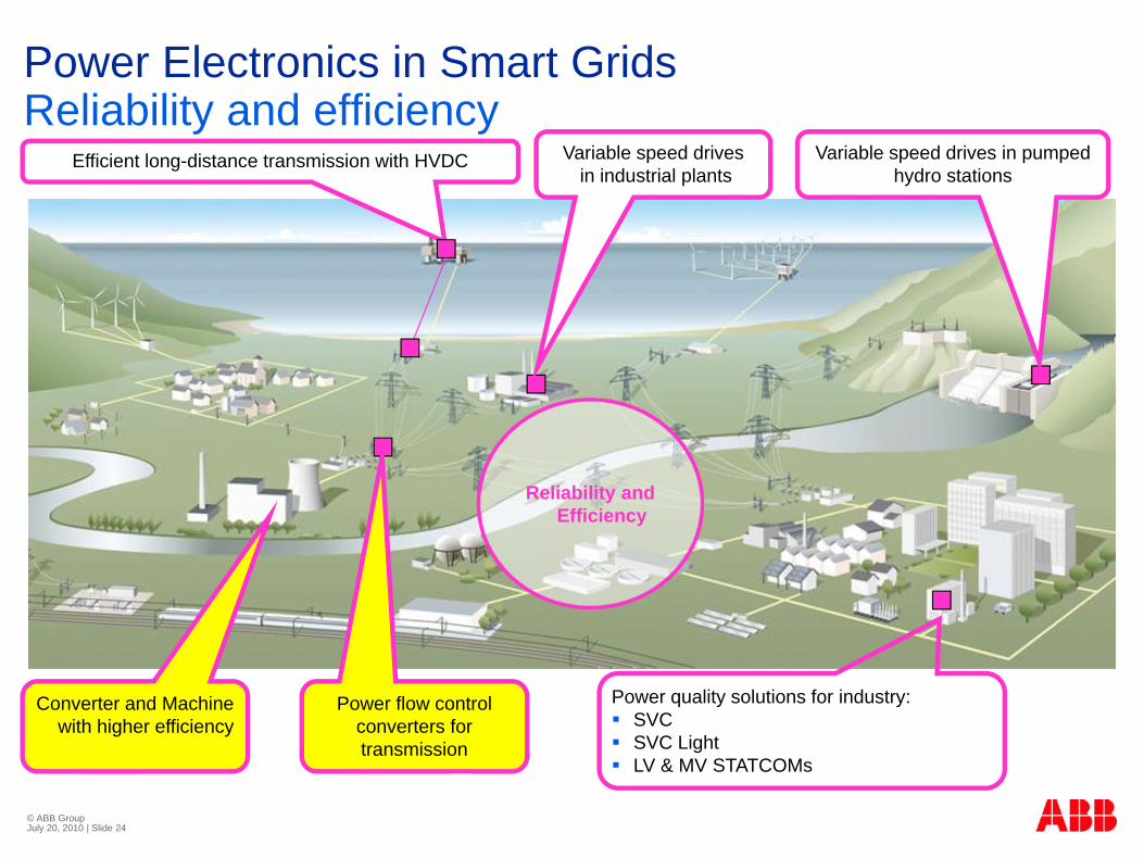
Power Electronics in Smart Grids Reliability and efficiency
Power quality solutions for industry: SVCSVC Light LV & MV STATCOMs
Efficient long-distance transmission with HVDC Variable speed drivesin industrial plants
Variable speed drives in pumped hydro stations
Reliability and Efficiency
Power flow control converters for transmission
Converter and Machine with higher efficiency
© ABB Group July 20, 2010 | Slide 25
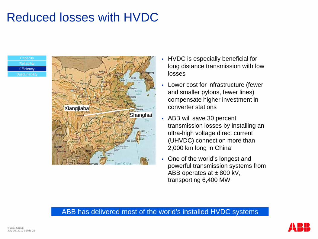
Reduced losses with HVDC
HVDC is especially beneficial for long distance transmission with low losses
Lower cost for infrastructure (fewer and smaller pylons, fewer lines) compensate higher investment in converter stations
ABB will save 30 percent transmission losses by installing an ultra-high voltage direct current (UHVDC) connection more than 2,000 km long in China
One of the world’s longest and powerful transmission systems from ABB operates at ± 800 kV, transporting 6,400 MW
ABB has delivered most of the world’s installed HVDC systems
CapacityReliabilityEfficiency
Sustainability
XiangjiabaShanghai

© ABB Group July 20, 2010 | Slide 26
MV DrivesWhy variable speed drives?
60 - 65% of industrial electrical energy is consumed by electric motors
For each 1 USD spent to purchase a motor, 100 USD are spent for energy cost during its lifetime
Today, only 5% of these motors are controlled by variable speed drives
30% of existing motors can be retrofitted with variable speed drives
The installed base of ABB drives saves more than 120 TWh of energy per year, the equivalent of 15 nuclear power plantsABB drives reduce CO2 emissions by approx. 60 million tons per year
© ABB Group July 20, 2010 | Slide 27
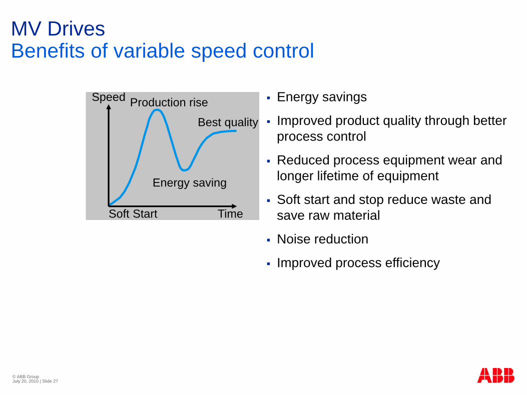
MV DrivesBenefits of variable speed control
Energy savings
Improved product quality through better process control
Reduced process equipment wear and longer lifetime of equipment
Soft start and stop reduce waste and save raw material
Noise reduction
Improved process efficiency
Production riseSpeed
Best quality
Energy saving
Soft Start Time
© ABB Group July 20, 2010 | Slide 28
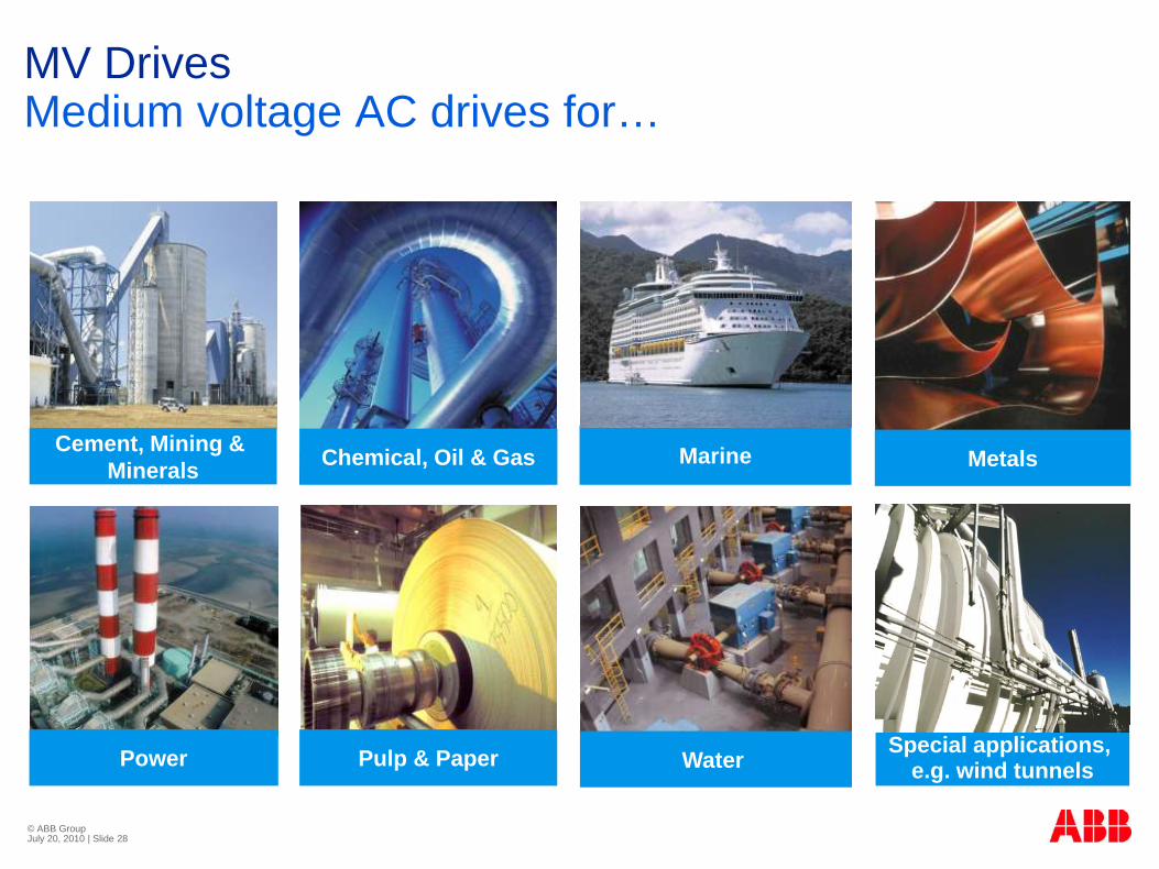
MV DrivesMedium voltage AC drives for…
Chemical, Oil & Gas
Power Water
Marine
Pulp & Paper Special applications, e.g. wind tunnels
MetalsCement, Mining & Minerals
© ABB Group July 20, 2010 | Slide 29
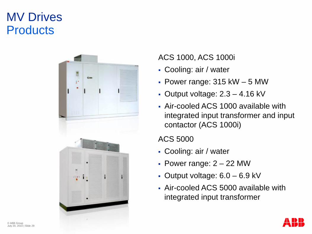
MV DrivesProducts
ACS 1000, ACS 1000iCooling: air / waterPower range: 315 kW – 5 MWOutput voltage: 2.3 – 4.16 kV Air-cooled ACS 1000 available with integrated input transformer and input contactor (ACS 1000i)
ACS 5000Cooling: air / waterPower range: 2 – 22 MWOutput voltage: 6.0 – 6.9 kVAir-cooled ACS 5000 available with integrated input transformer

© ABB Group July 20, 2010 | Slide 30
Power Electronics in Smart Grids Integration of electric vehicles
Traction drives for (hybrid) electric vehicles
Stations for fast charging of electric vehicles
Centralized energy storage (Dynapow) to absorbe peaks due to simultaneous (fast) charging of multiple electric vehicles
Integration of electric vehicles
Residential inverters for energy storage, renewables, and PHEV/EV
© ABB Group July 20, 2010 | Slide 31
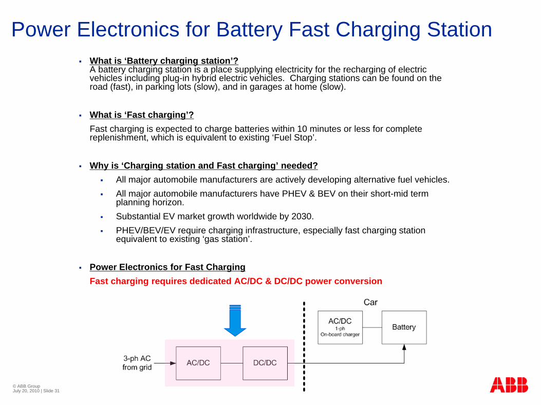
Power Electronics for Battery Fast Charging StationWhat is ‘Battery charging station’?A battery charging station is a place supplying electricity for the recharging of electric vehicles including plug-in hybrid electric vehicles. Charging stations can be found on the road (fast), in parking lots (slow), and in garages at home (slow).
What is ‘Fast charging’?Fast charging is expected to charge batteries within 10 minutes or less for complete replenishment, which is equivalent to existing ‘Fuel Stop’.
Why is ‘Charging station and Fast charging’ needed?All major automobile manufacturers are actively developing alternative fuel vehicles.All major automobile manufacturers have PHEV & BEV on their short-mid term planning horizon.Substantial EV market growth worldwide by 2030.PHEV/BEV/EV require charging infrastructure, especially fast charging station equivalent to existing ‘gas station’.
Power Electronics for Fast ChargingFast charging requires dedicated AC/DC & DC/DC power conversion

© ABB Group July 20, 2010 | Slide 32
Infrastructure of Battery Fast Charging StationAssumption:
A fleet of all electric vehicles with battery packs in the range of 25-50kWh (driving range of 100 – 200km)
Scenario:
A ten-minute quick charge from 10% to 90% capacity for 25kWh battery pack would require a power draw of about 120kW from the grid.
If average charging station is capable of serving 10 cars simultaneously, a ten-minute quick charge for all 10 vehicles refers to 1.2MW load. Charging station load would continuously fluctuate in the range of 0-1.2MW.
If there are 20 fast charging stations in a city, there will be continuous load fluctuation in the range of 0-24MW from a grid perspective.
© ABB Group July 20, 2010 | Slide 33
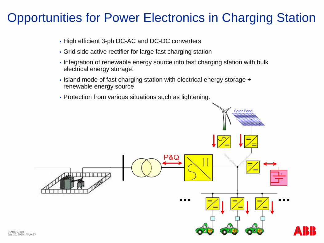
Opportunities for Power Electronics in Charging Station
High efficient 3-ph DC-AC and DC-DC converters
Grid side active rectifier for large fast charging station
Integration of renewable energy source into fast charging station with bulk electrical energy storage.
Island mode of fast charging station with electrical energy storage + renewable energy source
Protection from various situations such as lightening.

© ABB Group July 20, 2010 | Slide 34
Conclusion: Smart Grid Needs High MW Electronics
Current switching
Current interrupting
Current limiting
Transformer
Solid-state substation
Main Challenges:High reliability
Low losses
Thermal Management/Cooling
High switching frequency
High blocking voltage for direct MV connection
High power density/Footprint
Low cost
LV-a
pplic
atio
ns
