smart electronic fuel injection system using magnetic fuel vaporizer
TRANSCRIPT
http://www.iaeme.com/IJMET/index.asp 33 [email protected]
International Journal of Mechanical Engineering and Technology (IJMET) Volume 6, Issue 11, Nov 2015, pp. 33-42, Article ID: IJMET_06_11_004 Available online at http://www.iaeme.com/IJMET/issues.asp?JType=IJMET&VType=6&IType=11 ISSN Print: 0976-6340 and ISSN Online: 0976-6359
© IAEME Publication
SMART ELECTRONIC FUEL INJECTION SYSTEM USING MAGNETIC FUEL
VAPORIZER
Mr. Saurabh Murlidhar Chaudhari and Mr. Mitesh Hemant Salvi
Department of Mechanical Engineering YTIET, Karjat Mumbai University, India
ABSTRACT
The ever hike in the price of fuel in the world has created a big zeal to look
for an alternative to petrol/gasoline that are used to drive vehicles throughout the world. The emissions after the combustion has already created problems like Greenhouse effect and global warming. Technologies have tried their best
to look for solutions to this major concern that is increasing exponentially, nowadays. Taking this as a basis of research we decided to develop such a
system that will bring a considerable control in the emissions of the engine’s exhaust and with the assistance of some electronic sensors and transducers a viable injection system will be develop so as to achieve the maximum output
from the prototype engine and to achieve the longest mileage for many cars in future. Electronic mileage booster with magnetic fuel vaporizer combustion is basically an alternative or can be a replacement to conventional carburetor
equipped engines. The model is responsible for setting up the dynamic air fuel ratio in the intake manifold which provide the required power to the vehicle
rather than providing the constant ratio. The new concept of magnetic fuel vaporizer also helps to dissolve the carbon build-up in carburetor, jets, fuel injector and combustion chamber, thereby keeping the engines c lear
condition.
Key words: Electronic fuel injection system, magnetic fuel vaporizer and
greenhouse effect
Cite this Article: Mr. Chaudhari, S. M. and Mr. Salvi, M. H. Smart Electronic Fuel Injection System using Magnetic Fuel Vaporizer. International Journal
of Mechanical Engineering and Technology, 6(11), 2015, pp. 33-42. http://www.iaeme.com/IJMET/issues.asp?JType=IJMET&VType=6&IType=11
1. INTRODUCTION
1.1. Problem Statement
One of the main issues our society is facing is the constant increase in the temperature
of the earth’s atmosphere, also known as global warming. A rise in the temperature in

Mr. Saurabh Murlidhar Chaudhari and Mr. Mitesh Hemant Salvi
http://www.iaeme.com/IJMET/index.asp 34 [email protected]
the atmosphere can cause ice to melt around the Earth’s poles, a rise in sea level, and an increase in rainfall and snowfall worldwide. This phenomenon is mainly caused by
greenhouse gases produced by the burning of fossil fuels. According to the United States Environmental Protection Agency, 28% of greenhouse gas emissions come
from burning fossil fuels in transportation. Oil refined as gasoline to fuel cars, trucks, and other highway vehicles is the main fossil fuel used in transportation.
The Shell Eco-marathon competition is designed for students to find innovative
solutions in transportation to help reduce the release of greenhouse gas emissions in vehicles. This includes finding alternative energy sources as well as optimizing the
energy sources we have today. Our goal is to design and build well optimized fuel injection system with a car prototype that maximizes fuel efficiency of an internal combustion engine to compete in the Shell Eco-marathon Asia. This system can be
installed on all market vehicles to reduce emissions and increase mileage by few factors.
1.2. Scope
There is no doubt that this is the most flourishing technology in automotive sector. Almost the conventional vehicles have been replaced by hybrid and many of this has smart engine driving system. As per the rising need it is sure that in future the
conventional carbureted vehicles shall be replacement by this smart system. India still lag in this section. Hence there is huge scope to this.
2. STUDY AND SURVEY
2.1. Introduction
This section will focus on study and research done behind selection o f appropriate engine for our injection system as well as the detail specifications sensors and ECU of
the EFI kit.
2.2. Engine: Honda GX35
The engine selection for the Shell Eco-Marathon car is one of the most important aspects for the vehicle’s success. Since the goal is to improve fuel efficiency, finding
a motor that will be able to power the vehicle while using the least amount of power is important. Since the engine will be cycled on and off during the competition, overall
motor efficiency was deem more important than total power output. Most current small engine choices suffer from the same design flaw: they are carbureted. Carburetors deliver fuel less efficiently than fuel injection, hurting fuel economy.
Finding a motor that was fuel injected or that could be easily modified to become fuel injected is a priority. Motor compression ratios are another way to improve engine
efficiency. It is possible to improve engine compression by changing parts but using a motor that has a higher compression ratio to start with is a better option. As a small group, our budget is limited, so finding the best cost/performance ratio for the motor
is important.
Three main engine options were considered: a Honda GY6-QMB 50cc, a Honda
GX25 25cc, and a Honda GX35 35cc. Figure shows the GX35 engine that was selected. The engines were compared in terms of their power output, compression ratio, aftermarket support, starter type, clutch type, initial fuel consumption, and cost.
Table shows the decision matrix used to compare the engines. Engines were scored with possible values of 1, 5, and 10 with 10 being the best possible score and 5 being
the worst. The score is then weighted by the importance, giving the final total score.
Smart Electronic Fuel Injection System using Magnetic Fuel Vaporizer
http://www.iaeme.com/IJMET/index.asp 35 [email protected]
2.2.1. Power Output
In the category of power output, least is the best. The car will be light, so it will not
take a lot of power to achieve the desired speed. The GY6-QMB produces 2.1 kW at 6500 rpm and 3.1 N-m at 5500 rpm, the GX25 produces 0.72 kW at 7000 rpm and 1
N-m at 5000 rpm, and the GX35 produces 1 kW at 7000 rpm and 1.6 N-m at 5000 rpm [1]. The GX25 would produce enough power to move the car, while not producing any more than we need. Consequently, the GX25 scored the highest in this
category followed by the GX35 and last was the GY6-QMB.
2.2.2. Compression Ratio
Compression ratio of an engine is an important measure of thermodynamic efficiency: the higher the ratio, the more efficient the motor. Since the motor will be cycled, overall efficiency is just as important as initial fuel consumption. The GY6-QMB
starts with a compression ratio of 10.5:1 while the GX25 and GX35 both have Compression ratios of 8.0:1 [1]. The GY6-QMB scored the highest possible points in
this category while the GX25 and GX35 scored the lowest.
2.3. Ignition Type
Using an electric starter would make it possible for the driver to cycle the motor on and off while driving. Since the plan to improve vehicle efficiency is to cycle the
motor, having an electric starter is much better than having a magneto starter. The GX35 is the only motor of the 3 considered to have an electric starter, giving it the
maximum number of points for the category.
2.4. Fuel System
2.4.1. Overview
The team came up with three different concepts for the fuel system. Each one of these
concepts is based upon the same idea that the team is limited to gasoline as a fuel source. The team is also limited to many other constraints related to the fue l system. The team must use a Shell Eco-Marathon approved fuel tank of 30mL, 100mL, or
250mL. The team is also limited to certain clear no expansive fuel lines. With all of these constraints in place, there is only a few different concepts related to the fuel
system the team considered. These concepts are the use of carburetor, use of fuel injection, and the use of a forced induction fuel injected system. The first concept is the method of using a carburetor to deliver the fuel in the engine. This is how mo st
small engines are designed. It is a simple delivery system that does not require the need for computer processor or modules. It utilizes the mechanical appendances to
deliver fuel. A big problem with carburetors is that they cannot precisely tune a vehicle to the absolute best fuel efficiency. Another disadvantage with carburetors is that they commonly are in need of adjustment. This means decreased reliability and
increased maintenance.
The second concept is the method of fuel injection. Fuel injection sprays fuel
directly into the throttle body or into the cylinder depending on the system. This increases fuel efficiency because the spray is localized where combustion occurs. The system is very reliable once the team integrates it into the engine. Fuel injection also
allows for very accurate tuning with the assistance of software and electronics. It does take some time to set up the system and get the system producing the best fuel
efficiency results.
Figure 1 shows how fuel injection works.

Mr. Saurabh Murlidhar Chaudhari and Mr. Mitesh Hemant Salvi
http://www.iaeme.com/IJMET/index.asp 36 [email protected]
Figure 1 Direct Injection
2.4.2. Design Considerations
The team needed to decide which fuel system was best for the Eco-Marathon
competition application. The team determined criteria that would be divided into six sections for the fuel system: fuel efficiency, ease of implementation, precise tuning, reliability, maintenance, and cost. The team defined each of these criterions and gave
them a respective weighted percentage based upon importance. The team defines fuel efficiency as a percentage of fuel that is converted into propulsion energy. This is
measured in a percentage. This is the most important to the team because the more fuel efficient the fuel system is the less amount of fuel used to Propel the vehicle and overall a lower vehicle fuel efficiency. The team gave fuel efficiency a weighted
percentage of 40%. The team defines ease of implementation as the amount of time it would take to install the fuel system. This is important to the team because the simpler
the system is to integrate the more time the team has to test and tune. A simpler system is also easier to find potential problems and fix them. The team assigned ease of implementation with a weighted percentage of 10%. The team defines precise
tuning as how accurate the fuel system can be tuned to. This is very important to the team because the more precise the fuel system tuning is, the better the fuel efficiency
that can be obtained. The team assigned precise tuning with a weighted percentage of 20%.
The team defines reliability as the time it takes before the system has a problem
and needs maintenance. This is important because the team wants a fuel system that will hold true to the tuned characterizes. The team does not want to have to worry
about if the fuel system is going to fail during test runs or competition runs. For this reason the team gave reliability a weighted percentage of 15%. The team defines maintenance as the amount of time spent maintain fluids and retuning to keep best
fuel efficiency. This quantity will be measured in minutes. This is important to the team because the team does not want to spend a lot of time in between runs checking
and retuning the vehicle at the competition. The team assigned maintenance with a weighted percentage of 10%.
Smart Electronic Fuel Injection System using Magnetic Fuel Vaporizer
http://www.iaeme.com/IJMET/index.asp 37 [email protected]
The team defines fuel system cost to be the amount to purchase the fuel system, measured in dollars. This is not as important to the team because the whole objective
of this competition is to be as fuel efficient as possible. This means that a good amount of the budget will go into a fuel system. The team assigned fuel system cost to
have a weighted percentage of 5%.
3. ELECTRONIC FUEL INJECTION
3.1. Introduction
SE-EFI is an Electronic Fuel Injection conversion kit for small engines. This install
procedure is a customized version for the Honda GX35. It is only a hardware installation guide. It does not cover any tuning or ECU Programming. The locations
of the components are up to you, the ones shown here are preferred locations by some early adopters.
This EFI kit has below features:
Electronic fuel injection (EFI)
Quick engine start even at cold temperatures
More power and torque than the carbureted version
High fuel efficiency and low carbon emissions
fuel-cut-off
OBD - on board diagnosis
Performance tuning for advanced users.
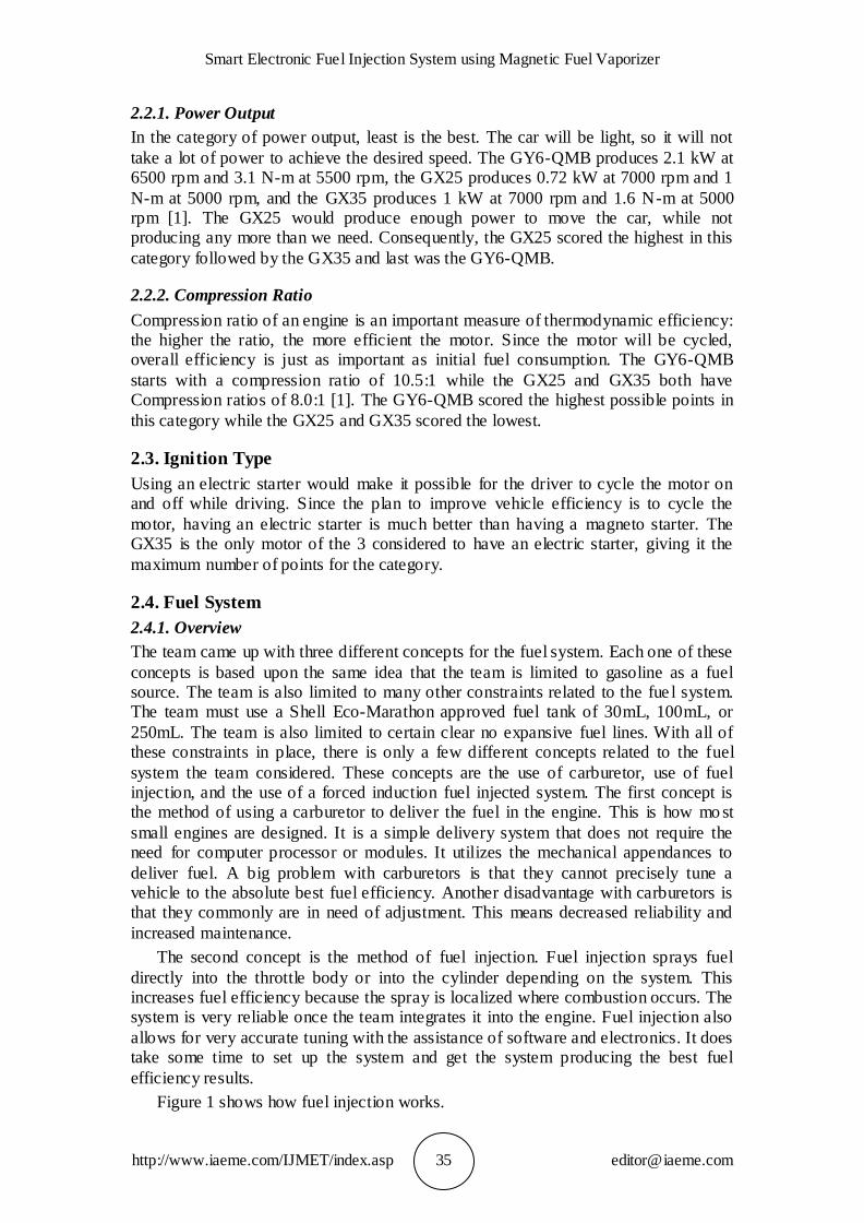
EFIJ- series fuel injectors are designed to inject the fuel into the intake manifold to
achieve a homogeneous distribution of fuel in air flow as efficiently as possible. The injectors are used on EFI system usually Injector consist the filter, electrical fittings, solenoid coil, the armature, needle valve, O-ring, seals and other components.
Figure 2 Transverse section of fuel injector
3.2. ECU
The core part of Ecotrons ECU is Free Scale’s 16 bit or 32 bit microprocessor that is specifically designed for powertrain controls. ECU also includes some Application
Mr. Saurabh Murlidhar Chaudhari and Mr. Mitesh Hemant Salvi
http://www.iaeme.com/IJMET/index.asp 38 [email protected]
Specific Integrated Circuits, or ASIC chips, from world famous automotive semiconductor manufacturers, like Infineon, and International Rectifier etc. Most
importantly, Ecotrons’
ECU contains the state-of-art engine control software which combines both
efficiency and flexibility of the modern engine control technology. Ecotrons has a few small engine ECUs; all small sizes and light weight. One is like the below picture, potted with the epoxy for weather proof. ECU judges the working state of the engine
through the sensor measuring data acquisition and calculation. ECU performs Optimization and control tasks according to the existing and stored calibration data.
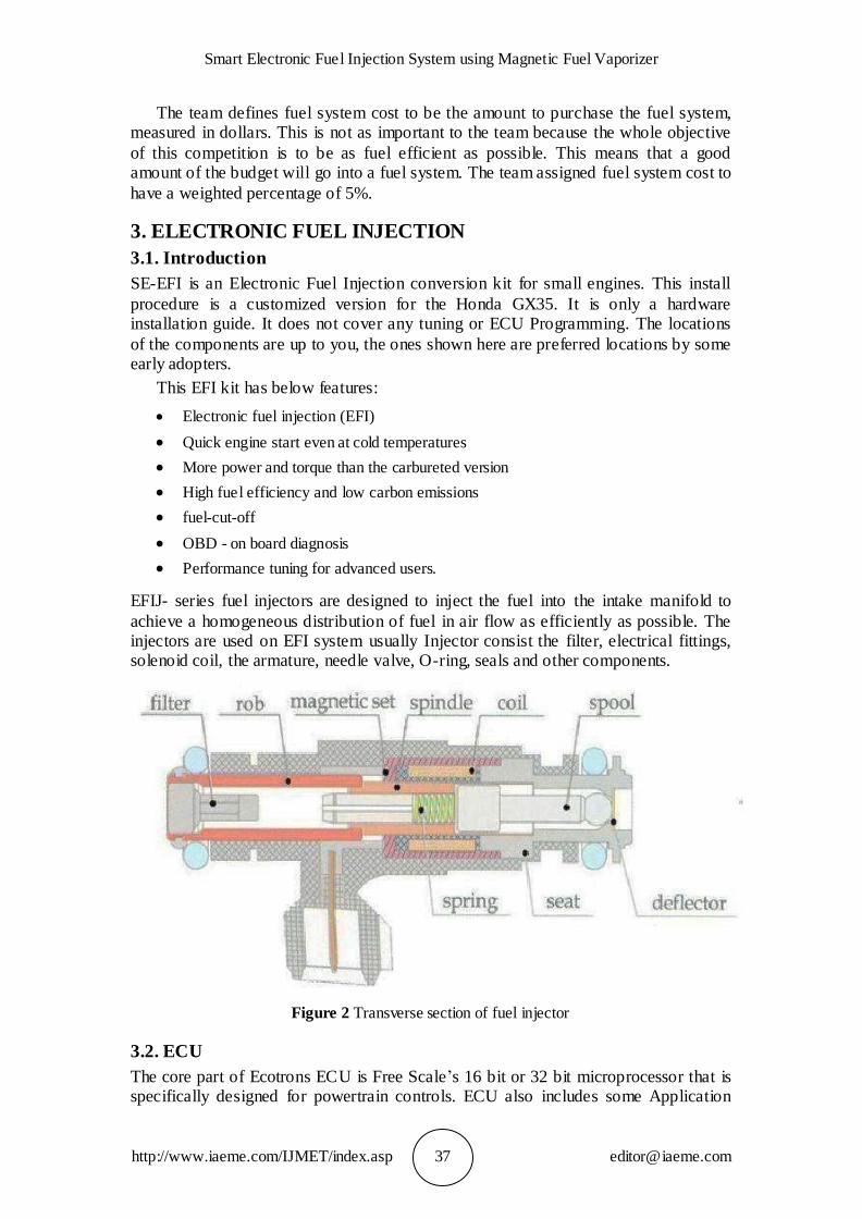
3.3. Installations
In order to ensure a high reliability, ECU installation should abide by the following principles:
Mounting position of ECU should have adequate ventilation.
Avoid the heat transmission to the ECU.
Away from the ignition system, the EMI is serious
It should be installed firmly.
Avoid the dirty, wet, and splash water.
Don’t let the ECU to prop up the wiring harness.
Wiring harness should avoid wear and heat.
Figure 3 Mounting
3.4. Installation
1. TPS sensor is not water submersible proof.
2. Avoid the sensor in a dusty or muddy environment. The dust or debris that might get into sensing element will cause deficiency of the sensor.
3. Every time a new sensor is installed or a new ECU is installed in Ecotrons EFI system, the TPS sensor idle position and WOT position will be self-adapted. To trigger this learning process is to create a “power fail” of ECU, meaning, with Key On, disconnect the ECU and then key off, then reconnect the ECU.
Smart Electronic Fuel Injection System using Magnetic Fuel Vaporizer
http://www.iaeme.com/IJMET/index.asp 39 [email protected]
4. Sensor mounting torque should not exceed 49.03mN * m (MAX), to prevent the sensor damaging.
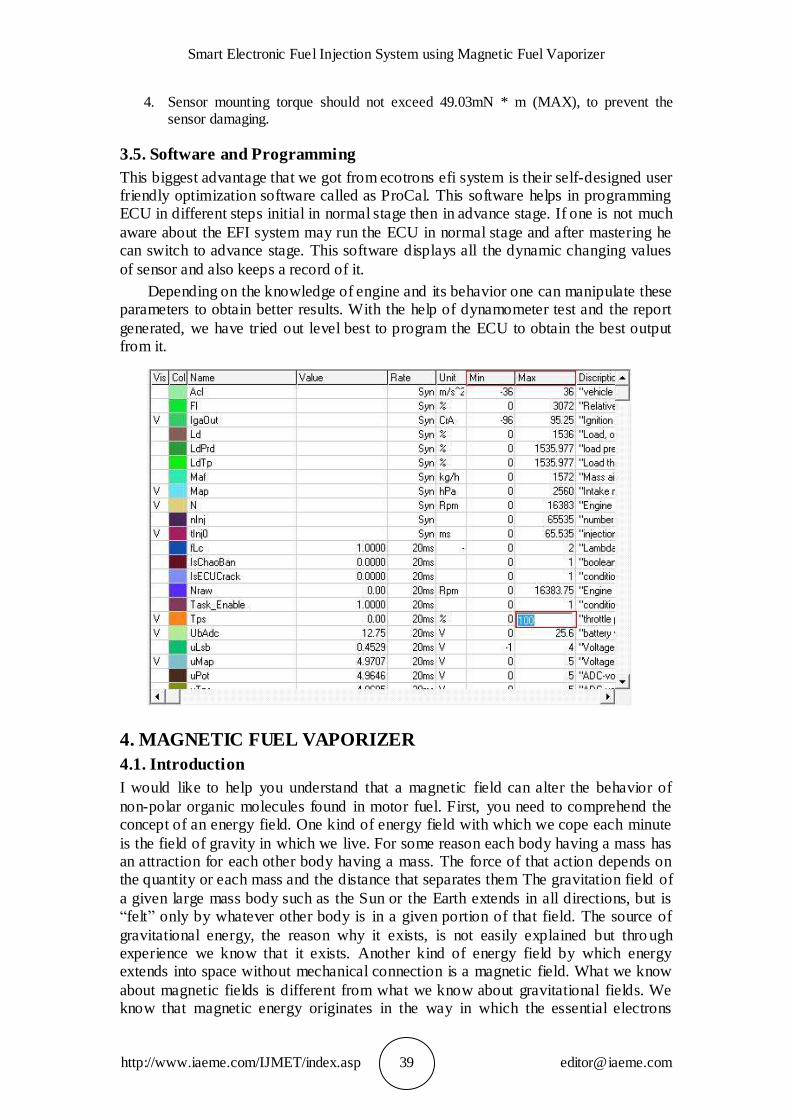
3.5. Software and Programming
This biggest advantage that we got from ecotrons efi system is their self-designed user friendly optimization software called as ProCal. This software helps in programming ECU in different steps initial in normal stage then in advance stage. If one is not much
aware about the EFI system may run the ECU in normal stage and after mastering he can switch to advance stage. This software displays all the dynamic changing values
of sensor and also keeps a record of it.
Depending on the knowledge of engine and its behavior one can manipulate these parameters to obtain better results. With the help of dynamometer test and the report
generated, we have tried out level best to program the ECU to obtain the best output from it.
4. MAGNETIC FUEL VAPORIZER
4.1. Introduction
I would like to help you understand that a magnetic field can alter the behavior of
non-polar organic molecules found in motor fuel. First, you need to comprehend the concept of an energy field. One kind of energy field with which we cope each minute
is the field of gravity in which we live. For some reason each body having a mass has an attraction for each other body having a mass. The force of that action depends on the quantity or each mass and the distance that separates them The gravitation field of
a given large mass body such as the Sun or the Earth extends in all directions, but is “felt” only by whatever other body is in a given portion of that field. The source of
gravitational energy, the reason why it exists, is not easily explained but thro ugh experience we know that it exists. Another kind of energy field by which energy extends into space without mechanical connection is a magnetic field. What we know
about magnetic fields is different from what we know about gravitational fields. We know that magnetic energy originates in the way in which the essential electrons
Mr. Saurabh Murlidhar Chaudhari and Mr. Mitesh Hemant Salvi
http://www.iaeme.com/IJMET/index.asp 40 [email protected]
found in all matter spin. This constant movement of electrons is described by a branch of mathematics called quantum mechanics, which, for the sake of the average reader,
we will not employ in this writing.
Most of the furiously moving electrons in most of the stable atoms and stable
molecules in the Universe are paired. For want of a truly intimate knowledge, we say that one electron of an electron pair is spinning in one direction and the other electron of the pair spinning in the opposite direction. Paired electrons with this balanced
arrangement exhibit no external magnetic activity, because the spin in one direction cancels the effect of the spin in the other direction. A magnetic field is set up when
somebody, for example an iron bar magnet or the
Earth’s core, has a lot of unpaired electrons, we say, spinning in the same direction. The energy influence of these unpaired electrons is transmitted through
space to affect other electrons in other bodies. A magnetic field is created by the magnetized iron bar magnet or the Earth’s core. For centuries mankind has been able
to see the effects of a magnet, without fully understanding how or why it works. A magnetic field extends into a finite space. The electrons in the atoms of matter coming into this magnetic field might be affected by the energy of the magnetic field in a
remote transfer of energy. Most of what is known about magnets involves polar materials in a magnetic field. For example, when mechanical energy is exerted to
make a metal rotate in a magnetic field, a flow of electrons (electricity) is created and the mechanical energy is converted into electric energy. In an electric motor the energy of moving electrons is converted to mechanical energy. Many other examples
of the behavior in a magnetic field of metals or polar inorganic and even polar organic materials have been studied. However, our concern is with completely non-polar
materials, where normally there are no electrons that are not neatly balanced in pairs. A hydrocarbon fuel consists of molecules made from atoms of carbon and hydrogen, which are collected by what are called covalent bonds. In such bonds an individual
atom will share a pair of electrons with a neighboring atom. Two carbon atoms might share two electrons and by doing so they are held together. Each carbon atom can be
connected in four different directions. For example, a given carbon atom might form a sharing partnership with two other carbon atoms in order to be a link in a chain. At the same time this same carbon atom will form a sharing partnership with two hydrogen
atoms. Each of the bonds, the C-C bonds or the C-H bonds consist of shared and paired electrons. Normally the two electrons in each covalent bond have balanced
opposite spins. “Normal” properties of non-polar molecules such as the hydrocarbons in gasoline, diesel fuel and related materials presuppose such electron spin-balanced chemical bonds.
Consider the properties of a liquid that can freeze to become a solid or vaporize to become a gas. Each hydrocarbon such as we are considering has a characteristic
temperature at which it will boil and a lower characteristic temperature at which it will freeze. In the series of hydrocarbons (that have no branched chains), both the melting point and the boiling point increase as a function of the molecular weight, or
the number of carbon atoms in the chain. The bigger the molecule, the higher the boiling temperature and the freezing temperature. Ordinary liquid fuels consist of
mixtures of hydrocarbon molecules of various sizes. In a fuel liquid held between the freezing (melting) point and the boiling point, where energy is constantly being transferred from one molecule to another as they vibrate and collide with each other,
some molecules will be close to the energy state at which they might fly off as a gas.
Smart Electronic Fuel Injection System using Magnetic Fuel Vaporizer
http://www.iaeme.com/IJMET/index.asp 41 [email protected]
Other molecules will be close to the energy state that allows them to “snuggle up” to another like molecule in what is the start of a chunk of solid material.
4.2. Effect of Magnetism on Fuel Molecules
Fuel molecule consists of a number of atoms made up of number of nucleus and electrons, which orbit their nucleus. Magnetic movements already exist in their
molecules and they therefore already have positive and negative electrical charges. However these molecules have not been realigned, the fuel is not actively interlocked with oxygen during combustion, the fuel molecule or hydrocarbon chains must be
ionized and realigned. The ionization and realignment is achieved through the application of magnetic field, as said by Paul (1993), Park K et al (1997).
Fuel mainly consists of hydrocarbon and when fuel flows through a magnetic field, the hydrocarbon change their orientation and molecules of hydrocarbon change their configuration. At the same time inter molecular force is considerably reduced or
depressed. These mechanisms are believed to help disperse oil particles and to become finely divided. This has the effect of ensuring that fuel actively interlocks
with oxygen producing a more complete burn in the combustion chamber. The result is better fuel economy and reduction in hydrocarbons, carbon monoxide and oxides of nitrogen that are emitted though exhaust. The ionization fuel also helps to dissolve the
carbon build-up in carburetor, jets, fuel injector and combustion chamber, thereby keeping the engines clear condition.
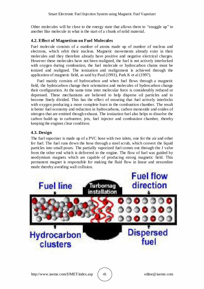
4.3. Design
The fuel vaporizer is made up of a PVC hose with two inlets, one for the air and other
for fuel. The fuel runs down the hose through a steel scrub, which convert the liquid particles into small pours. The partially vaporized fuel comes out through the J valve
from the other end which is delivered to the engine. The flow of fuel was guided by neodymium magnets which are capable of producing strong magnetic field. This permanent magnet is responsible for making the fluid flow in linear and streamline
mode thereby avoiding wall collision.
Mr. Saurabh Murlidhar Chaudhari and Mr. Mitesh Hemant Salvi
http://www.iaeme.com/IJMET/index.asp 42 [email protected]
4.4. Output
This vaporizer is capable of increasing the mileage of the vehicle by 30%, as vapors are more combustible than liquid. The use of this vaporizer in our vehicle succumbed
172kmp
5. CONCLUSION AND FUTURE SCOPE
Our new Smart Injection System with magnetic vaporizer will be installed on our race vehicle which will compete in Shell Eco Marathon 2016, Philippines. After making this a happening project we came to know that one can achieve increased mileage of
at least 25% which will thereby bring a considerable reduction on use of global fuel and this has become a prime reason for its increased use at global level. Almost 30%
of the commercial vehicle has employed such smart systems of different brands in order to obtain a better fuel economy and controlled emission.
REFERENCE
[1] R S Khurmi, J K Gupta, Theory of Machines, Eurasia Publishing House Pvt. Ltd., Distributors S. Chand and Company Ltd. for Toothed Wheels.
[2] V B Bhandari, Design of Machine Elements, Third Edition, McGraw Hill Education (India) Pvt. Ltd. for Rolling Contact Bearings
[3] Faculty of Mechanical Engineering, PSG College of Technology, Coimbatore, Printed and published by Kalaikathir Achchagam, Revised edition 1978 for Rolling Contact Bearing
[4] Automobile system- Dr. Kripal singh
[5] IC engines- Prof. Rajput
[6] Vehicle Dynamics-Thomas Gillespie
[7] A Text Book of Automobile Engineering R K Rajput Firewall Media, 2007 ISBN 8170089913, 97881700899
[8] S. Sunil Kumar Reddy and Dr. V. Pandurangadu. Theoritical Investigations of Injection Pressure in A Four Stroke DI Diesel Engine with Alcohol as Fuel. International Journal of Mechanical Engineering and Technology, 4(2), 2013, pp. 209–216.