smart data accelerator interface (“sdxi”) specification
TRANSCRIPT

1
Smart Data Accelerator Interface (“SDXI”) Specification
Version 0.9.0 rev 1
ABSTRACT: Smart Data Accelerator Interface (SDXI) is a proposed standard for a memory to memory Data Mover and acceleration interface.
Publication of this Working Draft for review and comment has been approved by the SDXI TWG. This draft represents a “best effort” attempt by the SDXI TWG to reach preliminary consensus, and it may be
updated, replaced, or made obsolete at any time. This document should not be used as reference material or cited as other than a “work in progress.” Suggestions for revisions should be directed to
http://www.snia.org/feedback/
Working Draft
July 2021
USAGE 2 Copyright © 2021 SNIA. All rights reserved. All other trademarks or registered trademarks are the property of their 3 respective owners. 4
The SNIA hereby grants permission for individuals to use this document for personal use only, and for corporations and 5 other business entities to use this document for internal use only (including internal copying, distribution, and display) 6 provided that: 7
1. Any text, diagram, chart, table or definition reproduced shall be reproduced in its entirety with no alteration, and, 8
2. Any document, printed or electronic, in which material from this document (or any portion hereof) is reproduced 9 shall acknowledge the SNIA copyright on that material, and shall credit the SNIA for granting permission for its 10 reuse. 11
12
Other than as explicitly provided above, you may not make any commercial use of this document or any portion thereof, 13 or distribute this document to third parties. All rights not explicitly granted are expressly reserved to SNIA. 14
Permission to use this document for purposes other than those enumerated above may be requested by e-mailing 15 [email protected]. Please include the identity of the requesting individual and/or company and a brief description of the 16 purpose, nature, and scope of the requested use. 17
18
All code fragments, scripts, data tables, and sample code in this SNIA document are made available under 19 the following license: 20
BSD 3-Clause Software License 21 22 Copyright (c) 2021, The Storage Networking Industry Association. 23 24 Redistribution and use in source and binary forms, with or without modification, are permitted provided that the 25 following conditions are met: 26 27 * Redistributions of source code must retain the above copyright notice, this list of conditions and the following 28 disclaimer. 29 30 * Redistributions in binary form must reproduce the above copyright notice, this list of conditions and the following 31 disclaimer in the documentation and/or other materials provided with the distribution. 32 33 * Neither the name of The Storage Networking Industry Association (SNIA) nor the names of its contributors may 34 be used to endorse or promote products derived from this software without specific prior written permission. 35 36 THIS SOFTWARE IS PROVIDED BY THE COPYRIGHT HOLDERS AND CONTRIBUTORS "AS IS" AND ANY 37 EXPRESS OR IMPLIED WARRANTIES, INCLUDING, BUT NOT LIMITED TO, THE IMPLIED WARRANTIES OF 38 MERCHANTABILITY AND FITNESS FOR A PARTICULAR PURPOSE ARE DISCLAIMED. IN NO EVENT 39 SHALL THE COPYRIGHT OWNER OR CONTRIBUTORS BE LIABLE FOR ANY DIRECT, INDIRECT, 40 INCIDENTAL, SPECIAL, EXEMPLARY, OR CONSEQUENTIAL DAMAGES (INCLUDING, BUT NOT LIMITED 41 TO, PROCUREMENT OF SUBSTITUTE GOODS OR SERVICES; LOSS OF USE, DATA, OR PROFITS; OR 42 BUSINESS INTERRUPTION) HOWEVER CAUSED AND ON ANY THEORY OF LIABILITY, WHETHER IN 43 CONTRACT, STRICT LIABILITY, OR TORT (INCLUDING NEGLIGENCE OR OTHERWISE) ARISING IN ANY 44 WAY OUT OF THE USE OF THIS SOFTWARE, EVEN IF ADVISED OF THE POSSIBILITY OF SUCH DAMAGE. 45
46

DISCLAIMER 47
The information contained in this publication is subject to change without notice. The SNIA makes no 48 warranty of any kind with regard to this specification, including, but not limited to, the implied warranties of 49 merchantability and fitness for a particular purpose. The SNIA shall not be liable for errors contained herein 50 or for incidental or consequential damages in connection with the furnishing, performance, or use of this 51 specification. 52
53
54

Revision History 55
56
Revision Date Comments v0.7 September 2020 Starting point Draft Contribution to SNIA SDXI TWG
v0.9 July 2021 First Public preview
57
58
59
Suggestions for revisions should be directed to http://www.snia.org/feedback/. 60 61
62
63
64
65
Smart Data Accelerator Interface (“SDXI”) Specification 66
[Status] 67
July 2021 68
69
70
71

SDXI TWG v0.9 Contributors 72
Philip Ng, AMD 73
Alexandre Romana, Arm 74
Glen Sescila, Dell Inc 75
Shyam Iyer, Dell Inc 76
Paul Von Stamwitz, Fujitsu 77
Curtis Ballard, HPE 78
Dwight Riley, HPE 79
Donald Dutile, Red Hat Inc. 80
Beau Beachamp, MemVerge 81
Jason Wohlgemuth, Microsoft 82
Murali Ravirala, Microsoft 83
Frederick Knight, NetApp 84
Bill Martin, Samsung 85
Santosh Kumar, SK Hynix 86
Rich Brunner, VMware 87
James Leighton, Western Digital 88
Paul Hartke, Xilinx 89
90
91

2 Working Draft SNIA SDXI Specification Version 0.9.0 rev 1
Table of contents 92
ABSTRACT: SMART DATA ACCELERATOR INTERFACE (SDXI) IS A PROPOSED STANDARD FOR A MEMORY TO 93 MEMORY DATA MOVER AND ACCELERATION INTERFACE. ................................................................................. 1 94
SDXI TWG V0.9 CONTRIBUTORS ............................................................................................................... 1 95
1 SDXI: OVERVIEW .................................................................................................................................... 6 96
1.1 SCOPE 6 97
1.2 OUTSIDE SCOPE 6 98
1.3 DOCUMENTATION CONVENTIONS ......................................................................................................... 6 99
Normative vs. Informative ........................................................................................................... 6 100
Reserved .................................................................................................................................... 6 101
Developer Notes ........................................................................................................................ 7 102
Abbreviations and Terminology .................................................................................................. 7 103
Other Clarifying Notes ................................................................................................................ 8 104
References ................................................................................................................................. 8 105
2 BACKGROUND ........................................................................................................................................ 9 106
2.1 ARCHITECTED PLATFORM DATA MOVER .............................................................................................. 9 107
SDXI Descriptor Ring .............................................................................................................. 10 108
Virtualization Support ............................................................................................................... 11 109
2.2 ADDRESSING MODES ........................................................................................................................ 12 110
PASID Usage ........................................................................................................................... 12 111
Address Spaces and Multi-Address-Space Operation .............................................................. 12 112
SDXI Function Groups ............................................................................................................. 13 113
Unpinned Memory Access ........................................................................................................ 14 114
2.3 MODULARITY AND EXPANDABILITY ..................................................................................................... 14 115
2.4 ENDIAN FORMAT SUPPORT ............................................................................................................... 15 116
3 SYSTEM MEMORY DATA STRUCTURES ............................................................................................ 16 117
3.1 OVERVIEW 16 118
3.2 CONTEXT DATA STRUCTURES ........................................................................................................... 16 119
Context Level 2 Table .............................................................................................................. 18 120
Context Level 1 Table .............................................................................................................. 19 121
Context Control Entry ............................................................................................................... 20 122
AKey Table Entry ..................................................................................................................... 22 123
Context Status Entry ................................................................................................................ 24 124
3.3 ADMINISTRATIVE CONTEXT (CONTEXT 0) ........................................................................................... 24 125

SNIA SDXI Specification Working Draft 3 Version 0.9.0 rev 1
3.4 ERROR LOG 24 126
Error Log Header Entry ............................................................................................................ 25 127
Descriptor Retry ....................................................................................................................... 30 128
3.5 SDXI MULTI-FUNCTION ACCESS ....................................................................................................... 30 129
SDXI Function Group ............................................................................................................... 30 130
RKey Processing ...................................................................................................................... 30 131
RKey Table .............................................................................................................................. 31 132
RKey Table Entry ..................................................................................................................... 31 133
4 SDXI FUNCTION AND CONTEXT STATE ............................................................................................. 33 134
4.1 SDXI FUNCTION STATE .................................................................................................................... 33 135
Stopped State .......................................................................................................................... 34 136
Initializing State ........................................................................................................................ 34 137
Active State .............................................................................................................................. 34 138
Soft Stop Request State ........................................................................................................... 34 139
Hard Stop Request State .......................................................................................................... 34 140
Stopped-On-Error State............................................................................................................ 35 141
4.2 SDXI CONTEXT STATE ..................................................................................................................... 35 142
Context Stopped/NotRunning States ........................................................................................ 35 143
Context Inactive State .............................................................................................................. 35 144
Context Ready State ................................................................................................................ 35 145
Context Running State ............................................................................................................. 37 146
Context Stopping State ............................................................................................................ 37 147
Context Stopping With Errors State .......................................................................................... 37 148
Context Error State ................................................................................................................... 37 149
5 SDXI DESCRIPTOR RING OPERATION ................................................................................................ 38 150
5.1 ENQUEUING ONE OR MORE DESCRIPTORS.......................................................................................... 40 151
Multi-Producer Enqueue ........................................................................................................... 43 152
5.2 DESCRIPTOR PROCESSING ............................................................................................................... 44 153
5.3 DESCRIPTOR ORDERING AND PARALLEL EXECUTION .......................................................................... 44 154
5.4 DESCRIPTOR COMPLETION ............................................................................................................... 45 155
5.5 MEMORY CONSISTENCY MODEL ........................................................................................................ 45 156
5.6 DESCRIPTOR CHAINING .................................................................................................................... 46 157
Extended Descriptors ............................................................................................................... 46 158
4 Working Draft SNIA SDXI Specification Version 0.9.0 rev 1
6 SDXI DESCRIPTOR AND OPERATION SPECIFICATION ..................................................................... 47 159
6.1 DESCRIPTOR FORMAT FOR SDXI OPERATIONS .................................................................................. 48 160
Common Header and Footer .................................................................................................... 48 161
Completion Status Block .......................................................................................................... 50 162
Attribute Field ........................................................................................................................... 50 163
6.2 DMA BASE OPERATIONS GROUP (DMABASEGRP) ............................................................................. 52 164
DmaBaseGrp: DS_DMAB_NOP ............................................................................................... 52 165
DmaBaseGrp: DS_DMAB_WRT_IMM Operation ..................................................................... 54 166
DmaBaseGrp: DS_DMAB_COPY Operation ............................................................................ 56 167
DmaBaseGrp: DS_DMAB_REPCOPY Operation ..................................................................... 58 168
6.3 ADMINISTRATIVE OPERATION GROUP (ADMINGRP) ............................................................................. 60 169
AdminGrp: DS_ADM_UPD_FUNC Operation ........................................................................... 61 170
AdminGrp DS_ADM_UPD_CXT Operation .............................................................................. 63 171
AdminGrp DS_ADM_UPD_AKEY Operation ............................................................................ 65 172
AdminGrp DS_ADM_START Operation ................................................................................... 67 173
AdminGrp DS_ADM_STOP Operation ..................................................................................... 69 174
AdminGrp DS_ADM_INTR Operation ....................................................................................... 71 175
AdminGrp DS_ADM_SYNC Operation ..................................................................................... 73 176
AdminGrp DS_ADM_UPD_RKEY Operation ............................................................................ 75 177
6.4 ATOMIC OPERATION GROUP (ATOMICGRP) ........................................................................................ 76 178
6.5 INTRGRP OPERATION GROUP ........................................................................................................... 79 179
IntrGrp DS_INTERRUPT Operation ......................................................................................... 79 180
6.6 VENDOR DEFINED OPERATION GROUP .............................................................................................. 81 181
7 FUNCTION INITIALIZATION AND CONTEXT MANAGEMENT ............................................................. 82 182
7.1 FUNCTION INITIALIZATION .................................................................................................................. 82 183
7.2 CONTEXT MANAGEMENT ................................................................................................................... 82 184
Caching of Memory Data Structures ......................................................................................... 82 185
Modify or Delete a Context Level 2 Table Entry ........................................................................ 83 186
Add Context Level 1 Table ....................................................................................................... 83 187
Modify or Delete a Context Level 1 Table Entry ........................................................................ 83 188
New Context Creation .............................................................................................................. 84 189
Modify a Context Control Entry ................................................................................................. 85 190
Modify or Delete an AKey Table Entry ...................................................................................... 85 191
Start a Context ......................................................................................................................... 86 192

SNIA SDXI Specification Working Draft 5 Version 0.9.0 rev 1
Restore and Resume a Context ............................................................................................... 86 193
Stop/Save a Context ................................................................................................................ 87 194
7.3 ERROR LOG PROCESSING ................................................................................................................. 87 195
Error Log Initialization ............................................................................................................... 87 196
Error Log Overflow Recovery ................................................................................................... 88 197
7.4 RESET 88 198
7.5 MAILBOX INTERFACE ........................................................................................................................ 88 199
7.6 DESCRIPTOR DRIVEN INTERRUPTS .................................................................................................... 88 200
8 SDXI PCI-EXPRESS DEVICE ARCHITECTURE .................................................................................... 89 201
8.1 SDXI FUNCTION CONFIGURATION SPACE REGISTERS ........................................................................ 89 202
Class Code............................................................................................................................... 89 203
BAR Configuration .................................................................................................................... 90 204
Required Capabilities and Extended Capabilities ..................................................................... 91 205
9 MMIO CONTROL REGISTERS .............................................................................................................. 92 206
9.1 GENERAL CONTROL AND STATUS REGISTERS .................................................................................... 93 207
9.2 CONTEXT AND RKEY TABLE REGISTERS ............................................................................................ 97 208
9.3 ERROR LOGGING CONTROL AND STATUS REGISTERS ......................................................................... 98 209
9.4 MBOX MAILBOX REGISTERS ........................................................................................................... 100 210
9.5 PF MAILBOX DATA REGISTERS ........................................................................................................ 102 211
9.6 VF MAILBOX DATA REGISTERS ........................................................................................................ 104 212
9.7 DOORBELL BAR 105 213
214

6 Working Draft SNIA SDXI Specification Version 0.9.0 rev 1
1 SDXI: Overview 215
This document describes SDXI, an architectural data-mover device for server platforms. SDXI aims to 216 provide a variety of benefits including architectural stability, modularity, virtualization-friendly programming 217 interface, both user and kernel mode support, and new capabilities designed to accelerate virtualized 218 workloads. 219
1.1 Scope 220
1.2 Outside Scope 221
1.3 Documentation Conventions 222
Shall, Should, May, and Can 223
This specification adheres to Section 13.1 of the IEEE Specifications Style Manual, which dictates use of 224 the words ‘shall’, ‘should’, ‘may’, and ‘can’ in the development of documentation, as follows: 225
• The word ‘shall’ is used to indicate mandatory requirements strictly to be followed in order to conform 226 to the Specification and from which no deviation is permitted (‘shall’ equals ‘is required to’). 227
• The use of the word ‘must’ is deprecated and shall not be used when stating mandatory 228 requirements; ‘must’ is used only to describe unavoidable situations. 229
• The use of the word ‘will’ is deprecated and shall not be used when stating mandatory requirements; 230 will is only used in statements of fact. 231
• The word ‘should’ is used to indicate that among several possibilities one is recommended as 232 particularly suitable, without mentioning or excluding others; or that a certain course of action is 233 preferred but not necessarily required; or that (in the negative form) a certain course of action is 234 deprecated but not prohibited (should equals is recommended that). 235
• The word ‘may’ is used to indicate a course of action permissible within the limits of the Specification 236 (may equals is permitted). 237
• The word ‘can’ is used for statements of possibility and capability, whether material, physical, or 238 causal (‘can’ equals ‘is able to’). 239
Normative vs. Informative 240
All sections are normative, unless they are explicitly indicated to be informative using conventions 241 described in 1.3. 242
Reserved 243
The following applies to the term ‘Reserved’: 244
• The contents, state, or information are not specified at this time. 245
• Any field, feature, capability, etc. marked ‘Reserved’ is subject to change. 246

SNIA SDXI Specification Working Draft 7 Version 0.9.0 rev 1
Developer Notes 247
Developer Notes do not specify normative or optional requirements. They are included for clarification and 248 illustration only. These notes are delineated by: 249
250
Developer Note: This is such a note … 251
Abbreviations and Terminology 252
253
Term Definition Administrative Context
A context that supports the use of administrative operations used for managing SDXI Functions and their contexts.
ATS Address Translation Services. Defined in the PCI Express Base Specification. Context A Context refers to a descriptor ring used for executing operations, along with
all associated memory data structures such as control and status information DMA Direct Memory Access Function Group A collection of SDXI functions that may generate DMA requests using each
other’s PCIe Requester IDs. GPA Guest Physical Address GVA Guest Virtual Address HPA Host Physical Address HVA Host Virtual Address IO Input Output IOMMU IO Memory Management Unit IOVA IO Virtual Address Local Local or Local Space refers to the SFuncHandle=0 value that corresponds to
the SDXI PCIe function hosting the context and descriptor. MMIO Memory mapped IO MMU Memory Management Unit PASID Process Address Space Identifier. The combination of PASID and Requester ID
identifies the address space used by a transaction on the PCIe bus. PIO Programmed I/O PRI Page Request Interface. Defined in the PCI Express Base Specification. Remote Remote or Remote Space refers to the use of a SFuncHandle value that is not
the Local one. Requester ID The PCIe bus, device and function number used by an SDXI function as part of
DMA and address translation operations. SDXI Function A PCIe endpoint function that implements the SDXI specification. This may be
either a physical or virtual function. SFuncHandle SDXI Function Handle is an opaque identifier that maps to an SDXI function’s
PCIe Requester ID. This is used when accessing AKey referenced data structures. The encoding is implementation specific other than the 0 value.
254
255

8 Working Draft SNIA SDXI Specification Version 0.9.0 rev 1
Other Clarifying Notes 256
1.3.5.1 Index 257
Index as used in this specification refers to a table index to a table-specific entry. In order to address the 258 corresponding table entry in memory, the index is multiplied by the size of the table-specific entry and added to 259 the beginning address of the table. For example, if a table starting at address 0x1000 has entries that are 64 260 bytes in size, then an index into that table needs to be multiplied by 64 and added to 0x1000 to determine the 261 correct memory location of the entry. 262 263
References 264
PCI Express Base Specification, Revision 5.0 265

SNIA SDXI Specification Working Draft 9 Version 0.9.0 rev 1
2 Background 266
The concept of a Direct Memory Access (DMA) data mover device to offload software-based copy loops is 267 well-known. Such offloading is desirable to free up CPU execution cycles. But adoption has been mostly 268 limited to specific privileged software and I/O use cases employing very device-specific interfaces that are 269 not forward compatible. The current limitations make user-mode application usage challenging in a non-270 virtualized environment and nearly impossible in a multi-tenant virtualized environment. The figure below 271 shows a vision for such an architectural data mover. 272
Figure 2-1 Architectural Data Mover 273
MMIO (Memory Mapped I/O)
SCM (Storage Class Memory)
Fabric Attached Memory
SDXI
System Physical Address space• Accelerate Data
Movement (CPU offloaded)
• Secure• Architectural, Stable
Interfaces
SW context isolation layers
Application(Context A) Application(Context B)
1. Leverage a standard specification
Direct User mode
2. Innovate around the spec
3. Add incremental Data acceleration
features
GPU
FPGA
SMART IO
CPU Family B SDXI
SDXI
SDXI
SDXI
CPU CPU Family A
DRAM(Context A)
DRAM(Context B)DRAM (Context B)
DRAM (Context A)
274
We have developed the SDXI Platform Data Mover (aka “SDXI”) to provide an architectural interface to 275 address these limitations: 276
• An extensible, forward-compatible interface that is independent of actual data mover implementations 277 and underlying I/O interconnect technology. 278
• A standard interface for user-mode address-space to address-space data movement without the 279 need of mediation by privileged software once a connection has been established. 280
• A standard interface for privileged software to control the data mover including connection 281 management and data movement between multiple address spaces 282
• An interface that can be abstracted or virtualized by privileged software to allow greater compatibility 283 of workloads or virtual machines across different servers. 284
• A well-defined capability to quiesce, suspend, and resume the architectural state of a per-address-285 space data mover to allow “live” workload or virtual machine migration between servers. 286
• A forward compatible interface that ensures pre-existing software drivers including user-mode drivers 287 can operate on future hardware implementations without modification. 288
• The ability to incorporate additional offloads in the future without modification to the architectural 289 interface. 290
2.1 Architected Platform Data Mover 291
The basic SDXI architecture consists of some number of Smart Data accelerators that are enumerated as 292 one or more PCIe endpoint functions. Each function may support 1 or more contexts with each context 293 having a single descriptor ring. SR-IOV is optionally supported. 294

10 Working Draft SNIA SDXI Specification Version 0.9.0 rev 1
Figure 2-2 Basic SDXI Architecture 295
SDXI Device
IOMMU
System Memory
SDXI Data Mover
PF0VF0_0VF0_nVF
0_0C
ntxt
0
DataDataData
VF0_
0Cnt
xtm
-1
PF0C
ntxt
n-1
PF0C
ntxt
0
VF0_
nCnt
xt0
VF0_
nCnt
xtm
-1
296
297
SDXI Descriptor Ring 298
An SDXI descriptor is a naturally aligned 64-byte entry that instructs an SDXI function to perform a given 299 operation. Descriptors are placed in a circular ring that starts at a specified address (DescRingBasePtr). 300 The ring is contiguous at the translation level configured for the SDXI function. The ring is configured to 301 contain a given number of descriptor ring entries (DescRingSize). The number of bytes allocated in 302 memory for the ring is: (DescRingSize * 64). 303
A set of related operations form an operations group. An operation requires a particular descriptor format 304 to indicate parameters for the operation. 305
The ring and all of its related system memory data structures comprise a “context”. SDXI uses a 2-level 306 hierarchy of context tables (Context Table Level 2, Context Table Level 1) to enumerate the components 307 of the context. The concatenation of the offsets used to enumerate a context in both Context tables yields 308 the 16-bit “context_number” that is associated with the context. (Note that the Context Tables point to a 309 context but are not themselves part of the context.) 310

SNIA SDXI Specification Working Draft 11 Version 0.9.0 rev 1
Figure 2-3 SDXI Descriptor Ring 311
A circular ring requires “start” and “end” indicators. Rather than using memory pointers to track these, an 312 SDXI descriptor ring uses 64-bit *unsigned* logical indices to indicate the start (ReadIndex) and end 313 (WriteIndex) of the descriptor ring. This simplifies various calculations for SW and HW alike. The logical 314 indices need only be mapped onto descriptor ring addresses when writing or reading a ring entry at a 315 given Index. All rings use the same mechanism to communicate between producer and consumer. 316
From the perspective of software, SDXI has two kinds of descriptor rings: 317
• A software producer ring. Software writes descriptors on to the ring, increments WriteIndex, and 318 writes to the doorbell to signal the SDXI function that a new descriptor has been written. The SDXI 319 function reads from the ring, increments ReadIndex, and performs the requested operation. With a 320 few exceptions noted in the next list item, all rings are software producer rings. 321
• A software consumer ring. The SDXI function writes log messages (using the format of descriptors) 322 on to the ring, increments WriteIndex, and can be configured to generate an interrupt to signal that a 323 new message has been written. Software reads from the log ring, increments ReadIndex, and 324 processes the requested message. The Error Log and the optional Administrative Log are two 325 examples of this kind of ring. 326
Virtualization Support 327
SDXI is architected specifically to allow operation within a virtualized environment. 328
Live migration is supported through a variety of accommodations in the programming model. During live 329 migration, a real hardware SDXI implementation may be stopped by the Hypervisor. Once stopped, there 330 is no hidden state. All critical state is located in either MMIO registers or in system memory. Another 331 instance may be configured with this state and restarted. It is possible to arbitrarily transition between 332 hardware and software emulated implementations. 333
DRBp + (N-1) * 64 DRBp + (1) * 64
DRBp
EntryAddresses
(Wraps every N*64 bytes)
Index = 0, N, 2*N, ...
Index = N-1, 2*N-1, 3*N-1, ...
Index = 1, N+1, 2*N+1, ...
Indices(Do not Wrap)
ReadIndex:
WriteIndex-1:
WriteIndex:
ValidEntry
FreeEntry
FreeEntry
FreeEntry
FreeEntry
ValidEntry
SDXI DescriptorQueue Ring
N = DescQueueSize (Number of entries in Queue)DRBp = DescriptorRingBasePtr
Indices are from 0 to (2^64)-1
EntryAddress = DescRingBasePtr + ((Index % DescQueueSize) << 6)WriteIndex - ReadIndex <= DescQueueSize
Where Consumer can start reading enqueued entries
Index of last enqueued entry to be read by Consumer
Where producer can start enqueueing
more entries

12 Working Draft SNIA SDXI Specification Version 0.9.0 rev 1
The programming model allows a Hypervisor to hide features from newer implementations and 334 specifications from a VM. This facilitates migration of a VM built around older versions of the specification 335 onto newer hardware. 336
Specific use cases around virtualized environments may be accelerated by SDXI. See Address Spaces 337 and Multi-Address-Space Operation. 338
Hardware implementations may be virtualized using standard PCIe SR-IOV techniques. There are slight 339 differences in the SDXI programming model between PF and VF implementations described in this 340 specification. In general, it is assumed that a Hypervisor would take control over PFs and allow VFs to be 341 directly mapped into VMs. 342
2.2 Addressing Modes 343
SDXI is designed to support multiple address spaces to facilitate a number of data movement use cases. 344 In combination with a supporting IOMMU, SDXI may make memory accesses using guest virtual, guest 345 physical or system physical addresses. 346
PASID Usage 347
Guest virtual space is accessed by tagging DMA requests with a Process Address Space Identifier 348 (PASID) that indexes into an appropriate IOMMU guest page table external to the SDXI function. This 349 allows DMA directly into user processes. The SDXI programming model allows control structures, 350 descriptors and data buffers to each be optionally located in a guest virtual space facilitating the 351 implementation of user-mode rings and access to user process data. Traditional descriptor rings and data 352 buffers located in kernel space are also supported. 353
Address Spaces and Multi-Address-Space Operation 354
Each SDXI physical or virtual function, like generic PCIe functions, can be considered to support DMA 355 access to one or more address spaces defined by their PCIe Requester ID, and optionally, a set of PASID 356 values. In general, the address spaces will be mapped as appropriate by privileged software. 357
A basic memory copy operation may reference two distinct memory data buffers. Privileged software may 358 want to use the copy operation to copy a data buffer from one address space to another. Traditionally this 359 would require some form of software address translation, or some scheme of mapping multiple address 360 spaces into a shared memory address space. Under SDXI this is greatly simplified. 361
Typically, a PCIe function can only access address spaces mapped using its own Requester ID. A unique 362 capability of SDXI functions is the optional ability to access memory buffers using address spaces 363 accessible by other SDXI functions. SDXI determines the address space of each data buffer using an 364 AKey value which is used to look up an AKey table entry. This entry provides SFuncHandle which maps to 365 the Requester ID of an SDXI function within the SDXI Function Group. The AKey table entry also provides 366 an optional PASID value. 367
Consider the example where a Hypervisor and a number of virtual machines (VMs) each have an SDXI 368 function (physical or virtual) assigned to them - FnCntl, FnSrc, FnDst - and those functions are located 369 within the same SDXI function group. The descriptor ring and all other control structures would be 370 associated with the Hypervisor’s FnCntl function and would be fetched using DMA FnCntl’s Requester ID. 371 The descriptor may then indicate the appropriate address spaces for both the source and destination data 372 buffers as belonging to FnSrc and FnDst. When reading the source buffer, DMA from SDXI will appear as 373 a read from FnSrc, and when writing the destination buffer, DMA from SDXI will appear as writes from 374 FnDst. In all cases, addresses may be either Guest Virtual or Guest Physical. All addresses would be 375 translated by the IOMMU using existing page tables. 376

SNIA SDXI Specification Working Draft 13 Version 0.9.0 rev 1
The figure below shows an example of such an operation. 377
Figure 2-4 Example Operation 378
F(TFFuncHandle)
Akey Table
DMA Read{RID0, PASID_A}DMA Read Completion DMA Write{RID2, PASID_C}
DMA Read{RID1, PASID_B}DMA Read Completion
Descriptor
Desc Type
Attr
DstAkey SrcAkey
SrcAddress
DstAddress
CompletionSignal
Address Space A Address Space CAddress Space B
Implementation defined Function. (Maps SFuncHandle to appropriate Requester IDs)
Akey Table (Allowed address Spaces)
AKEY 0 {SFuncHandleX, PASID_A}
IOMMUSF0: RID0 + PASID_A
SDXI Device
SF 0(“ FnSrc”)
SF 2(“ FnDst ”)
SF 1(“FnCtl”)
IOMMUSF1: RID1 + PASID_B
IOMMUSF2: RID2 + PASID_C
Producer
AKEY 1 {SFuncHandleZ, PASID_C}
F(SFuncHandle)SFuncHandle
RequesterID
379
380
Note that a multi-address space data movement solution can be achieved using two SDXI functions as 381 well as a single SDXI function. If FnDst or FnSrc are not equal to FnCtl, they may protect access to their 382 address spaces using the RKey feature. See 3.5 SDXI Multi-Function Access and 3.5.2 RKey Processing 383 for more details. 384
SDXI Function Groups 385
One of the conditions for allowing an SDXI function to access an address space owned by another SDXI 386 function is that both functions must belong to the same SDXI Function Group. An SDXI PF and its 387 associated VFs always belong to the same function group. A function group may contain multiple PFs and 388 VFs. A system may contain multiple disconnected function groups. 389
Function groups are discovered using the GroupID field in the MMIO registers. The method of 390 communication between SDXI functions within a function group is outside the scope of this specification. 391
392

14 Working Draft SNIA SDXI Specification Version 0.9.0 rev 1
Figure 2-5 SDXI Function Groups 393
IOMMU 1
SR-IOV SDXI Device 0
IOMMU 0
System Memory
PF1VF1_0VF1_n
VF1_
0Cnt
xt0
DataDataData
Multiple SDXI devices within an SDXI Function Group
VF1_
0Cnt
xtm
-1
PF1C
ntxt
n-1
PF1C
ntxt
0
VF1_
nCnt
xt0
VF1_
nCnt
xtm
-1
PF0VF0_0VF0_n
VF0_
0Cnt
xt0
DataDataData
VF0_
0Cnt
xtm
-1
PF0C
ntxt
n-1
PF0C
ntxt
0
VF0_
nCnt
xt0
VF0_
nCnt
xtm
-1
SR-IOV SDXI Device 1
394
Unpinned Memory Access 395
SDXI supports the use of unpinned memory through the use of the PCIe-defined ATS and PRI features. 396 The SDXI programming model does not explicitly identify whether data structures reside in unpinned 397 memory. If the PCIe ATS and PRI features are enabled within a function, an SDXI implementation must 398 assume that any memory accesses associated with that function’s address spaces may target unpinned 399 memory. 400
2.3 Modularity and Expandability 401
SDXI is architected as a modular and expandable framework for offload functions. While the initial 402 specification is focused on copy operations, additional offloads may be defined and added to newer 403 versions of the specification, as well as newer implementations. All new features shall be explicitly 404 discovered and enabled by supporting software. Implementations may choose to implement different sets 405 of offload capabilities. 406
In general, all SDXI OS/VM and user-level software is expected to operate transparently on any hardware 407 implementation that supports the same or newer version of the specification that the software was 408 designed for, as long as all of the expected offload capabilities are present. 409

SNIA SDXI Specification Working Draft 15 Version 0.9.0 rev 1
2.4 Endian Format Support 410
The SDXI specification is written assuming a little-endian architecture. Support for other endian formats is 411 outside the scope of this specification. 412

16 Working Draft SNIA SDXI Specification Version 0.9.0 rev 1
3 System Memory Data Structures 413
3.1 Overview 414
The following figure depicts all of the memory-addressed data structures used by an SDXI function. In 415 order to facilitate efficient software-based virtualization, the majority of an SDXI function’s architectural 416 state resides in system memory and is described in this chapter. The remaining state resides in a small 417 number of MMIO control registers (described in Chapter 9) and PCI Function configuration space registers 418 (described in Chapter 8). This layout of memory structures is designed to facilitate selective trapping by 419 privileged software. 420
Figure 3-1 Memory-Addressed Data Structures 421
422
3.2 Context Data Structures 423
An SDXI context represents the memory structures needed to directly monitor or control the operation of a 424 descriptor ring. An SDXI context consists of a descriptor ring, and the associated Context Control Entry 425 (CCE), Context Status Entry (CSE), AKey Table, and WriteIndex structures. Memory buffers and 426

SNIA SDXI Specification Working Draft 17 Version 0.9.0 rev 1
completion signals which descriptor ring entries operate upon are not considered part of the SDXI function 427 context; however, they are an important part of the additional corresponding state that software manages 428 directly in order to use the descriptor ring. 429
SDXI uses a 2-level hierarchy of context tables (Context Table Level 2, Context Table Level 1) to 430 enumerate the components of the context. The concatenation of the 9-bit Level 2 offset with the 7-bit Level 431 1 offset yields the 16-bit “context_number” that is associated with the context. (Note that the Context 432 Tables point to a context but are not themselves part of the context.) MmioCap1.NContexts indicates the 433 maximum supported context number. 434
An SDXI function will not access portions of the contexts table associated with context numbers greater 435 than MmioCap1.NContexts. See the example below. 436
Figure 3-2 MmioCap1.NContexts Example 437
Context Level 1 Table
Lvl 1 Ptr for contexts 0 to 127Lvl 1 Ptr for contexts 128 to 255
. . .Other Entries Are Invalid
Context 128: CCE and AKey PtrsContext 129: CCE and AKey Ptrs
. . .Other Entries Are Invalid
Context 255: CCE and AKey Ptrs
Context 0: CCE and AKey PtrsContext 1: CCE and AKey Ptrs
. . .Other Entries Are Valid
Context 127: CCE and AKey Ptrs
Context Level 1 Table
Context Level 2 Table
Example: MmioCap1.NContexts = 128
438
439

18 Working Draft SNIA SDXI Specification Version 0.9.0 rev 1
Context Level 2 Table 440
The Context Base Table register points to the 4KB level 2 table containing an array of level 2 table entries 441 described below. Each of those entries is a pointer to a level 1 table. A level 2 table contains 512 level 1 442 pointers. 443
444
Figure 3-3 Context Level 2 Table Entry 445
446
447
Table 3-1 Context Level 2 Table Entry 448
Bits Field Description
0 V Valid. When 1, indicates the other bits in this data structure are valid. When 0, all other bits in this data structure shall be ignored.
11:1 Reserved
63:12 ContextLvl1TableBasePtr Pointer to the start of a Context Level 1 table. This points to an aligned 4K region of memory.
449
31 30 29 28 27 26 25 24 23 22 21 20 19 18 17 16 15 14 13 12 11 10 9 8 7 6 5 4 3 2 1 0
DWORD0 V
DWORD1
ContextLvl1TableBasePtr[31:12] Rsvd
ContextLvl1TableBasePtr[63:32]

SNIA SDXI Specification Working Draft 19 Version 0.9.0 rev 1
Context Level 1 Table 450
Each of the level 1 table structures is a 4K naturally aligned piece of memory containing an array of 451 context level 1 table entries described below. A Context level 1 table has 128 entries. 452
Figure 3-4 Context Level 1 Table Entry 453
454
Table 3-2 Context Level 1 Table Entry 455
Bits Field Description
0 V Valid. When 1, indicates the other bits in this data structure are valid. When 0, all other bits in this data structure shall be ignored.
1 A Active. 1=Context is active and may execute descriptors. 0=Context is inactive and is blocked from executing descriptors.
2 PV PASID Valid. Indicates the ContextPASID field is valid.
5:3 Reserved
63:6 ContextControlPtr Pointer to a Context Control Entry. This points to a 64B aligned region of memory.
67:64 AKTSize AKeyTableSize. Indicates the size of the AKey table referenced by AKeyTableBasePtr. The table size is encoded as 2(AKTSize+12) bytes or 2(AKTSize+7)
entries. Encodings greater than 0x8 are reserved.
75:68 Reserved
127:76 AKeyTableBasePtr Pointer to the start of an AKey table. This points to a 4Kbyte aligned region of memory.
147:128 ContextPASID If PV=1, indicates the PASID value used in combination with the SDXI function’s Requester ID to access the WriteIndex, Context Status Entry, Completion Signal and Descriptor Ring. If PV=0, this field is not used and the WriteIndex, Context Status Entry, Completion Signal and Descriptor Ring are accessed using the SDXI function’s Requester ID but without a PASID.
151:148 MaxBuffer Indicates the maximum data buffer size supported by this context. The size is encoded as 2(MaxBuffer+21). Descriptor type or the size of the buffer length field within certain types of descriptors may further limit the maximum data buffer size for certain types of operations. This field should not be set to exceed MmioControl2.MaxBufferCntl
159:152 Reserved
31 30 29 28 27 26 25 24 23 22 21 20 19 18 17 16 15 14 13 12 11 10 9 8 7 6 5 4 3 2 1 0
DWORD0 PV A V
DWORD1
DWORD2
DWORD3
DWORD4
DWORD5
DWORD6
DWORD7
ContextControlPtr[63:32]
ContextControlPtr[31:6] Rsvd
Rsvd
Rsvd
AKeyTableBasePtr[31:12]
AKeyTableBasePtr[63:32]
CmdGrp0Support
ContextPASIDMaxBufferRsvd
AKTSizeRsvd

20 Working Draft SNIA SDXI Specification Version 0.9.0 rev 1
Bits Field Description
191:160 CmdGrp0Support Each bit in this field is set to 1 to indicate whether a certain group of optional descriptors is supported within this context. The encoding of the bits matches the MmioCapabilities1.CmdGrp0Support register.
255:192 Reserved
456
Context Control Entry 457
The Context Control Entry contains control information for a single descriptor ring. 458
Software shall expose the memory containing the context control entry as readable to the SDXI function 459 hosting the context. Software shall expose the memory containing the descriptor ring and the write index 460 as read-write to the SDXI function hosting the context. 461
This structure is intended to be controlled by privileged software. 462
Figure 3-5 Context Control Entry 463
464
465
31 30 29 28 27 26 25 24 23 22 21 20 19 18 17 16 15 14 13 12 11 10 9 8 7 6 5 4 3 2 1 0
DWORD0 R SH R V
DWORD1
DWORD2
DWORD3
DWORD4
DWORD5
DWORD6
DWORD7
DWORD8
DWORD9
DWORD10
DWORD11
DWORD12
DWORD13
DWORD14
DWORD15
DescRingBasePtr[31:6] QoS
DescRingBasePtr[63:32]
DescRingSize
WriteIndexPtr[31:3] Rsvd
ContextStatusPtr[63:32]
ContextStatusPtr[31:4] Rsvd
Rsvd
WriteIndexPtr[63:32]
Rsvd
Rsvd
Rsvd
Rsvd
Rsvd
Rsvd
Rsvd
Rsvd

SNIA SDXI Specification Working Draft 21 Version 0.9.0 rev 1
466
Table 3-3 Context Control Entry 467
Bits Field Description
0 V Valid. When 1, indicates the other bits in this data structure are valid. When 0, all other bits in this data structure shall be ignored.
1 Reserved
3:2 QoS Quality of service indicator.
Value Definition 00b Urgent 01b High 10b Medium 11b Low
The usage of this field is implementation specific.
4 SH Sequential Consistency Hint. 1=Descriptor ring is expected to set the S bit in most descriptors.
5 Reserved
63:6 DescRingBasePtr Pointer to the start of the descriptor ring. This points to a 64-byte aligned region of memory
95:64 DescRingSize Descriptor ring size. Indicates the size of the descriptor ring in 64-byte units.
131:96 Reserved
191:132 ContextStatusPtr Pointer to the Context Status data structure which includes the read index value. This points to a 16B aligned region of memory.
194:192 Reserved
255:195 WriteIndexPtr Pointer to descriptor ring write index. This points to an 8B aligned region of memory.
511:256 Reserved
468
469

22 Working Draft SNIA SDXI Specification Version 0.9.0 rev 1
AKey Table Entry 470
The AKey table is a 4-Kbyte aligned contiguous memory structure composed of AKey table entries. The 471 table may be any power-of-2 size from 4-Kbytes up to 1-Mbyte. Software controls the size of the table 472 through the context level 1 entry structure. Software chooses the size of the table based on its contiguous 473 memory allocation capabilities. 474
The descriptor may reference any AKey associated with the same ring context. The AKey table entries 475 encode all of the valid address spaces, PASIDs and interrupts available to the context. 476
Figure 3-6 AKey Table Entry 477
478
Table 3-4 AKey Table Entry 479
Bits Field Description
0 V Valid. When 1, indicates the other bits in this data structure are valid. When 0, all other bits in this data structure shall be ignored.
1 IV Interrupt Valid. When 1, the InterruptNumber field is valid.
2 PV PASIDValid. When 1, the PASID field contains valid information.
3 SE Steering Enable. When 1, memory requests referencing this AKey table entry are enabled for PCIe Transaction Processing Hints* and set PCIe TH=1 if TPH is also enabled through the TPH Requester Extended Capability. 0=TPH is disabled for memory requests referencing this AKey table entry.
14:4 InterruptNumber Interrupts generated using this AKey table entry are issued using the specified SFuncHandle and the MSI-X entry corresponding to InterruptNumber.
15 Reserved
31 30 29 28 27 26 25 24 23 22 21 20 19 18 17 16 15 14 13 12 11 10 9 8 7 6 5 4 3 2 1 0
DWORD0 R SE PV IV V
DWORD1
DWORD2
DWORD3
TargetSFuncHandle InterruptNumber
PASID
SteeringTagPHRsvd
Rsvd
RKeyRsvd

SNIA SDXI Specification Working Draft 23 Version 0.9.0 rev 1
Bits Field Description
31:16 TargetSFuncHandle TargetSFuncHandle specifies the target function within the SDXI function group which owns data buffers associated with the AKey table entry. TargetSFuncHandle is set to the target function’s MmioCapabilities0.SFuncHandle value. TargetSFuncHandle is an opaque identifier that maps to the target function’s PCIe Requester ID which is used when accessing the data buffer. The TargetSFuncHandle encoding of 0 is used to indicate the same function that is executing the descriptor and which owns the AKey table. A function may not use its own MmioCapabilities1.SFuncHandle value in its AKey table entries to reference its own Requester ID. It must use the 0 encoding for this purpose. See 2.2.3 SDXI Function Groups for more details.
51:32 PASID PASID value used for requests using this AKey table entry.
63:52 Reserved
79:64 SteeringTag When SE=1 and ST Mode Select in the TPH Requester Extended Capability = Device Specific, this field provides up to 16 bits of steering tag information through the PCIe ST field for memory requests that reference this AKey table entry. Steering tag information is generated through standard PCIe controls if ST Mode Select is not set to the device specific mode.
81:80 PH Processing Hint. When SE=1, this field supplies the 2-bit PH field for memory requests that reference this AKey table entry.
95:82 Reserved
111:96 RKey Specifies the RKey value used to access another function’s data buffer. This field is only valid if TargetSFuncHandle is non-zero. See 5.7 RKey Processing for more details
*Refer to the PCI-Express Base Specification for further details on Transaction Processing Hints. 480
481

24 Working Draft SNIA SDXI Specification Version 0.9.0 rev 1
Context Status Entry 482
The Context Status Entry contains status information for a single descriptor Context. If made accessible to 483 a user process, it is exposed as a read-only structure to software. 484
When creating the context, software shall initialize the status entry to all-zero prior to making the context 485 valid. 486
Software shall expose the memory containing the Context Status Entry as read-write to the SDXI function 487 using the context address space. 488
Figure 3-7 Context Status Entry 489
490
Table 3-5 Context Status Entry 491
Bits Field Description
3:0 ContextState Context State. 0000b = Stopped 0001b = Running 0010b = Stopping 1111b = Error All other encodings reserved
7:4 Reserved
63:8 Reserved
127:64 ReadIndex Descriptor ring read index.
3.3 Administrative Context (Context 0) 492
Administrative operations are used by privileged software to manage the SDXI function and are only 493 supported in Context 0 (“Administrative” Context) within each function. 494
An Administrative Context only supports “AdminGrp, ConnectGrp and other specified administrative 495 operations; no other operation groups including the DmaBaseGrp operations are supported. A VF 496 Administrative Context may be used to manage contexts associated with that VF. A PF Administrative 497 Context may be used to manage contexts hosted by the PF or contexts hosted by any VF associated with 498 the PF. 499
500
3.4 Error Log 501
Each SDXI function supports an Error Log message ring configured through MMIO space. 502
31 30 29 28 27 26 25 24 23 22 21 20 19 18 17 16 15 14 13 12 11 10 9 8 7 6 5 4 3 2 1 0
DWORD0
DWORD1
DWORD2
DWORD3 ReadIndex[63:32]
Rsvd
ReadIndex[31:0]
ContextStateRsvd

SNIA SDXI Specification Working Draft 25 Version 0.9.0 rev 1
Even though descriptors may reference data buffers in different address spaces and may detect errors 503 when accessing those buffers, all errors are logged with the function hosting the context. 504
The error log is a software consumer ring and is structured similar to a descriptor ring. 505
An SDXI function writes an error log header entry to the error log whenever an error is detected. For errors 506 associated with a descriptor, a copy of the descriptor is written into the error log after the header entry. 507 Descriptors written into the error log will have their Valid bit set to 1. 508
During descriptor processor errors may be detected and logged at different processing stages for a single 509 descriptor resulting in multiple error logs. Only one error may be logged for errors occurring during the 510 execution of the descriptor operation. Refer to 5.2 Descriptor Processing for more details. 511
The error log is empty when ErrLogWptr is equal to ErrLogRptr. Error log entries are written in increments 512 of 64 bytes. When an error log entry is written, ErrLogWptr will be advanced by 1 for each 64 byte unit 513 written, and ErrLogStatus will be set. 514
An interrupt will be generated when the error log is written if ErrLogInterruptEn=1. If MSI or MSI-X are 515 enabled, vector 0 will be used for the error log interrupt. 516
Software may process error log entries and then advance ErrLogRptr by 1 for each 64byte unit processed. 517
The function may simultaneously process multiple descriptors from the same ring. The order in which error 518 log entries are written is implementation-dependent even for descriptors within the same ring. 519
A context with context-specific errors, as indicated by CV=1 in the error log header will stop processing 520 new descriptors. If the context status entry is accessible, it will start transitioning to the Error state. 521
The error log will overflow if there is insufficient space to write a complete log entry when required. The 522 ErrorLogStatus.ErrLogOverflow bit is set on an overflow event. Error logging is stopped when the overflow 523 bit is set. Contexts may continue to run even when the error log is full or in the overflow state, however 524 detailed error information for new errors will be lost. 525
The function may be halted if an uncorrectable error prevents further safe operation across all of its 526 associated contexts. This is reflected in Status0.GlobalState. The function does not transition all of its 527 contexts into the error state when this occurs. 528
Errors may be reported on DMA write operations. While DMA writes are posted in PCI-Express and do not 529 return any status, write response status may be available in implementations that do not connect using a 530 physical PCIe link. 531
Error Log Header Entry 532
Error log header entries provide error status information about a specific error event. The ErrLogType and 533 ErrLogSubType fields provide information about the error condition. An implementation may use any of the 534 ErrLogSubType encodings in combination with any ErrLogType encodings as appropriate. 535
The CV, AV and IV flags indicate whether detailed information about the context number, memory address 536 and descriptor index are provided. 537
The RT flag indicates that the affected descriptor may be retried by software. See section 0 for more 538 details. 539
Error log header entries are formatted similar to SDXI descriptors but use a unique Type encoding to avoid 540 aliasing with real operations. See 6.1.1 Common Header and Footer for more details. 541
If a descriptor encountering an error is logged with the header, the header entry and the descriptor are 542 linked together by setting the Chain bit in the error log header. See 5.6 Descriptor Chaining for more 543 details on the use of the Chain bit. 544

26 Working Draft SNIA SDXI Specification Version 0.9.0 rev 1
An Extended Descriptor may be written into the error log after an error log header entry. If an Extended 545 Descriptor is written into the error log, the header entry ErrIndex field shall point to the starting index of the 546 Extended Descriptor in the context descriptor ring. 547
Figure 3-8 Error Log Header Entry 548
549
31 30 29 28 27 26 25 24 23 22 21 20 19 18 17 16 15 14 13 12 11 10 9 8 7 6 5 4 3 2 1 0
DWORD0 C V
DWORD1 RT IV AV CV
DWORD2
DWORD3
DWORD4
DWORD5
DWORD6
DWORD7
DWORD8
DWORD9
DWORD10
DWORD11
DWORD12
DWORD13
DWORD14
DWORD15
ErrAddress [31:0]
Rsvd
ErrAddress [63:32]
ErrIndex[31:0]
ErrIndex[63:32]
SubType=ErrLogType Type=0x7F7
ErrLogSubType ErrContextNumber
Rsvd
Rsvd

SNIA SDXI Specification Working Draft 27 Version 0.9.0 rev 1
Table 3-6 Error Log Header Entry 550
Bits Field Description
0 V Valid. When 1, indicates the other bits in this data structure are valid. When 0, all other bits in this data structure shall be ignored.
11:1 Type 0x7F7 = Error Log Header Entry
19:12 SubType The SubType field is used to encode the error log type. See below for encodings.
30:20 Reserved
31 C Chain. Indicates whether the error log header is followed by 1 or more descriptors in the error log.
47:32 ErrContextNumber Context number associated with the error log entry.
51:48 Reserved
52 CV Context Number Valid. Indicates whether the context_number field contains valid information.
53 AV Address Valid. 1=The ErrAddress field contains valid information.
54 IV Index Valid. 1=The ErrIndex field contains valid information.
55 RT Retry. 1=The referenced descriptor may be retried. Only valid in conjunction with descriptor errors (IV=1 and C=1).
63:56 ErrLogSubType Error log sub-type. See below for encodings.
127:64 ErrAddress Error Address. Valid if AV=1. Address associated with the error.
191:128 ErrIndex Error Index. Valid if IV=1. Descriptor index associated with the error.
511:192 Reserved
551
552
28 Working Draft SNIA SDXI Specification Version 0.9.0 rev 1
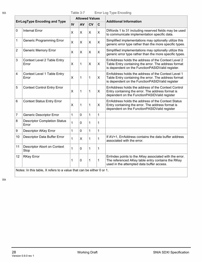
Table 3-7 Error Log Type Encoding 553
ErrLogType Encoding and Type Allowed Values
Additional Information IV AV CV C
0 Internal Error X X X X DWords 1 to 31 including reserved fields may be used to communicate implementation specific data.
1 Generic Programming Error X X X X Simplified implementations may optionally utilize this generic error type rather than the more specific types.
2 Generic Memory Error X X X X Simplified implementations may optionally utilize this generic error type rather than the more specific types.
3 Context Level 2 Table Entry Error X 1 X X
ErrAddress holds the address of the Context Level 2 Table Entry containing the error. The address format is dependent on the FunctionPASIDValid register.
4 Context Level 1 Table Entry Error X 1 1 X
ErrAddress holds the address of the Context Level 1 Table Entry containing the error. The address format is dependent on the FunctionPASIDValid register
5 Context Control Entry Error X 1 1 X
ErrAddress holds the address of the Context Control Entry containing the error. The address format is dependent on the FunctionPASIDValid register
6 Context Status Entry Error X 1 1 X
ErrAddress holds the address of the Context Status Entry containing the error. The address format is dependent on the FunctionPASIDValid register
7 Generic Descriptor Error 1 0 1 1
8 Descriptor Completion Status Error 1 0 1 1
9 Descriptor AKey Error 1 0 1 1
10 Descriptor Data Buffer Error 1 X 1 1 If AV=1, ErrAddress contains the data buffer address associated with the error.
11 Descriptor Abort on Context Stop 1 0 1 1
12 RKey Error 1 0 1 1
ErrIndex points to the AKey associated with the error. The referenced AKey table entry contains the RKey used in the attempted data buffer access.
Notes: In this table, X refers to a value that can be either 0 or 1.
554

SNIA SDXI Specification Working Draft 29 Version 0.9.0 rev 1
Table 3-8 Error Log Sub-Type 555
ErrLog SubType Summary Description
0 Reserved
1 Generic uncorrectable error The SDXI function must be reset prior to restarting operation.
2 Non-zero reserved field A reserved field contained a non-zero value. Support for this sub-type is optional. Implementations are not required to detect all possible reserved field violations.
3 Unsupported field encoding Unsupported encoding in a supported field.
4 ATS address translation error An ATS request was returned with error status. This encoding is not used for permission faults unless the Page Request Interface (PRI) feature is disabled or halted.
5 ATS address translation returned poisoned data
An ATS request was returned with poisoned data.
6 PASID out of range A PASID value outside the implementation-supported range was detected.
7 PRI error received PRI response received with an error response code.
8 PRI timeout Timeout waiting for PRI response. The timeout time is implementation specific.
9 Reference to invalid AKey table entry
Referenced AKey table entry is either invalid, contains an error, or is outside the range of the AKey table.
10 Reserved
11 Memory access returned with unsupported request status
12 Memory access returned with completer abort status
13 Memory access returned with poisoned data
14 Timeout accessing memory DMA request timed out. The timeout value is implementation specific.
15 Index Error Invalid combination of WriteIndex and ReadIndex values. For example, WriteIndex < ReadIndex or WriteIndex – ReadIndex > DescRingSize. This subtype is also used to indicate an Index rollover at 264.
556

30 Working Draft SNIA SDXI Specification Version 0.9.0 rev 1
Descriptor Retry 557
Descriptor errors with RT=1, IV=1, and C=1 set in the error log header may be retried by software. An 558 SDXI function may only mark an error log entry as RT=1 if memory consistency has not been violated. 559
Retrying a descriptor generally involves software correcting the underlying cause of the error, copying the 560 descriptor into an appropriate context, possibly with modifications, and re-executing it. Software shall 561 determine whether any underlying error conditions are correctable and whether to attempt a retry. Further 562 details are outside the scope of this specification. 563
While multiple descriptors from the same context may be written into the error log out-of-order, descriptors 564 must be retried in a valid order that reproduces the memory consistency of the original descriptor ring 565 ordering. The original descriptor ordering may be determined using the error log header 566 ErrContextNumber and ErrIndex fields. 567
Software may determine that all error logs for a context have been written by checking whether the context 568 status value has been changed to Error. 569
Retry may not be possible on an error log overflow event. 570
Implementations are encouraged to generate error logs with RT=1 where possible. 571
3.5 SDXI Multi-Function Access 572
There can be multiple interacting SDXI functions in a system if supported by the SDXI implementation. 573 Typically, a PCIe function can only access address spaces mapped using its own Requester ID. A unique 574 capability of an SDXI function is the optional ability to access address spaces mapped by the Requestor 575 ID of another SDXI function. 576
When executing a descriptor operation, the SDXI function determines the address space for each 577 specified data buffer or interrupt target by using the associated AKey value to reference an AKey table 578 entry. This entry provides SFuncHandle which maps to the Requester ID of an SDXI function within the 579 SDXI Function Group. When SFuncHandle is non-zero, the request is to another target or receiving 580 function. 581
The receiving function can optionally control which remote functions are permitted to attempt access using 582 the Receiver-side (function) Key Table (RKEY) mechanism. 583
SDXI Function Group 584
When an SDXI Function returns MmioCapabilities1.SDXI_MF as ‘1’, the function supports SDXI multi-585 function access and provides the Receiver-side (function) Key Table (RKEY) mechanism; otherwise, these 586 mechanisms are not supported. Note that SDXI multi-function access when supported is only possible for 587 SDXI functions that belong to the same SDXI Function Group. An SDXI PF and its associated VFs always 588 belong to the same function group. A function group may contain multiple PFs and VFs. A system may 589 contain multiple disconnected function groups. Function groups are discovered using the 590 MmioControl0.GroupID field in each SDXI function. 591
In a multi-function implementation of SDXI, all functions connected within an SDXI function group reflect 592 the same GroupID value written into any group member’s copy of this register. Software may identify all 593 functions within a function group by writing a non-zero value into the GroupID field of one function and 594 scanning for the same value in other SDXI functions. The GroupID register is only used to identify 595 functions within the same SDXI function group. It is not referenced by other SDXI registers or data 596 structures. 597
The method of coordination and configuration between SDXI functions within a function group is outside 598 the scope of this specification. 599
RKey Processing 600
SNIA SDXI Specification Working Draft 31 Version 0.9.0 rev 1
The Receiver-side (function) Key Table (RKEY) mechanism is used by a target (receiving) function to 601 control access to its data buffers from remote requesting functions within the same SDXI function group. 602
When a data buffer’s AKey table entry specifies an SFuncHandle value of zero (i.e. the access is within a 603 function), RKey processing for that access is skipped. When SFuncHandle is non-zero (i.e. the access is 604 across functions), RKey processing is attempted using the following checks below. 605
1. Requesting function passes its own SFuncHandle value along with the AKey table entry’s RKey 606 value and, if present, PASID, to the target function indicated by TargetSFuncHandle. 607
2. If the target function has MmioCapabilities1.SDXI_MF=0, abort the remote access. 608
3. Target function uses the supplied RKey value as an index into its RKey table to obtain the 609 associated RKey table entry. If the RKey table is not enabled 610 (MmioRKeyTblBase.RKeyTableEn=0), or the RKey table entry is not valid, abort the remote access. 611
4. Target function checks if the RKey table entry RequesterSfuncHandle match the requester 612 SFuncHandle. If not, abort the remote access. 613
5. Target function checks if the RKey table entry has PV=0. If so, it then checks that the requesting 614 function did not supply a PASID value, otherwise the remote access is aborted. 615
6. Target function checks if the RKey table entry has PV=1. If so, it then checks that the requesting 616 function supplied a PASID value and that the value matches the PASID value in the RKey table 617 entry. If not, the data buffer access is aborted. 618
RKey Table 619
The RKey table is a 4-Kbyte aligned contiguous memory structure composed of 8-byte RKey table entries. 620 The table may be any power-of-2 size from 4-Kbytes up to 512-Kbytes. Software controls the size of the 621 table through MmioRKeyTblBase.RKeyTableSize. 622
Software controlling the function may use IOMMU page tables in combination with PASID and RKey 623 values to selectively expose data buffers to different requesting functions. 624
Errors associated with failed RKey table entry checks are logged at the requesting function. No errors are 625 logged at the target function. 626
Error log entries associated with failed RKey table entry checks are marked as RT=0 and cannot be 627 retried. 628
RKey checks are performed for each descriptor referenced data buffer which is owned by another SDXI 629 function. This is implied when the data buffer AKey table entry contains a non-zero TargetSFuncHandle. 630
A connection manager specification is proposed for development by the SNIA SDXI TWG post publication 631 of Smart Data Accelerator Interface (“SDXI”) Specification v1.0. Please refer to it for mechanisms to 632 allocate and exchange RKeys between functions. 633
634
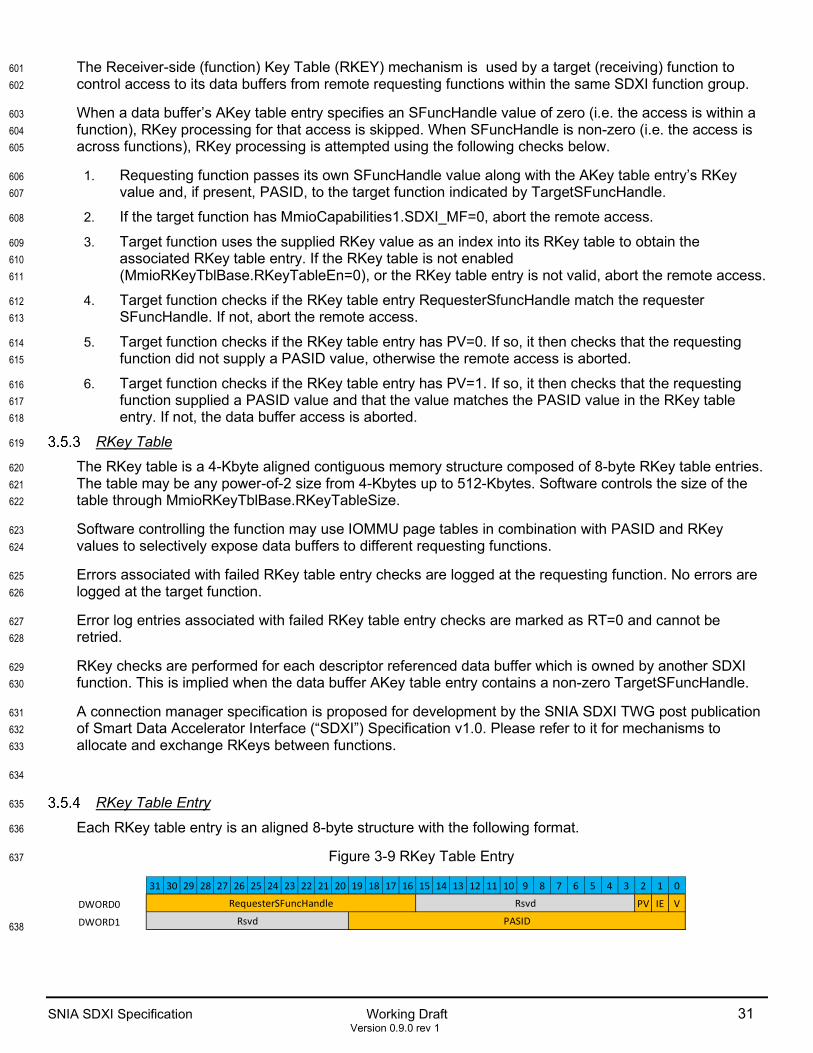
RKey Table Entry 635
Each RKey table entry is an aligned 8-byte structure with the following format. 636
Figure 3-9 RKey Table Entry 637
638
31 30 29 28 27 26 25 24 23 22 21 20 19 18 17 16 15 14 13 12 11 10 9 8 7 6 5 4 3 2 1 0
DWORD0 PV IE V
DWORD1
RsvdRequesterSFuncHandle
Rsvd PASID

32 Working Draft SNIA SDXI Specification Version 0.9.0 rev 1
Table 3-9 RKey Table Entry 639
Bits Field Description
0 V Valid. When 1, indicates the other bits in this data structure are valid. When 0, all other bits in this data structure shall be ignored and remote requesting functions may not use the RKey value associated with this entry to access data buffers owned by this function.
1 IE Interrupt Enable. When 1, Requesting functions referencing this RKey table entry are permitted to generate interrupt requests via this function. When 0, interrupt requests generated by referencing this RKey table entry are ignored.
2 PV PASIDValid. When 1, the PASID field contains valid information.
15:3 Reserved
31:16 RequesterSFuncHandle RequesterSFuncHandle specifies the SFuncHandle value of the remote requesting function expected to reference this RKey table entry. See <> for more details.
51:32 PASID PASID value used to access data buffers using this RKey entry
63:52 Reserved
*Refer to the PCI-Express Base Specification for further details on Transaction Processing Hints. 640
641

SNIA SDXI Specification Working Draft 33 Version 0.9.0 rev 1
4 SDXI Function and Context State 642
4.1 SDXI Function State 643
An SDXI function operates in one of 6 basic states reflected by the MmioStatus0.GlobalState register and 644 shown in the figure below. Software may use the MmioControl0.Enable register to help transition the 645 function between the various states. 646
Figure 4-1 SDXI Function States and State Transitions 647
648
649
GlobalState = 001b(Initializing)
GlobalState = 000b(Stopped)
GlobalState = 101b(Stopped On Error)
GlobalState = 010b(Active)
GlobalState = 011b(Soft Stop Step)
Reset
GlobalState = 100b(Hard Stop Step)
GlobalState is MmioStatus0.GlobalStateEnable is MmioControl0.Enable
Enable 11b
Function InitComplete
Enable Legend00b: Request Stop 01b: Request Soft Stop10b: Request Hard Stop11b: Request Active
One or more contexts failed to stop

34 Working Draft SNIA SDXI Specification Version 0.9.0 rev 1
Stopped State 650
The function is idle and not enabled to process any memory data structures or perform DMA operations. 651
From the Stopped state, software may set MmioControl0.Enable=11b. The function will attempt to 652 transition through the Initializing state into the Active state. Software shall program 653 ContextTableBase.ContextLvl2TableBasePtr prior to setting MmioControl0.Enable=11b. 654
Initializing State 655
The function self-initializes in the initializing state. If initialization is successful, the function transitions to 656 the Active state. If an error occurs during the initialization that prevents the processing of all contexts, the 657 function writes an appropriate error log and transitions to the Stopped-On-Error state. 658
It is an error (Generic Programming Error/Invalid Field Encoding) for software to program 659 MmioControl0.Enable to a value other than 11b when the function is in the Initializing state. 660
Active State 661
In the Active state, the function is enabled to process contexts and descriptors. 662
From the Active state, privileged software may request the function stop by writing Mmio0Control0Enable 663 to 10b to request a hard stop or to 01b to request a soft stop. 664
It is an error (Generic Programming Error/Invalid Field Encoding) for software to clear 665 MmioControl0.Enable to 00b when the function is in the Active state. 666
If an error occurs that prevents the processing of all contexts, the function writes an appropriate error log 667 and transitions to the Stopped-On-Error state 668
Soft Stop Request State 669
In the Soft Stop Request state, the function shall stop processing new descriptors and wait for all 670 outstanding descriptors to complete. The function shall wait until all outstanding descriptors complete 671 naturally or until an implementation-defined timeout period has expired at which point any remaining 672 descriptors are aborted. 673
When all contexts are stopped, the function transitions to the Stopped state. If an error occurs that 674 prevents one or more contexts from stopping, errors are logged, if possible, and the function instead 675 transitions to the Stopped-On-Error state. Descriptor errors including aborts alone do not drive a transition 676 to the Stopped-On-Error state. 677
Hard Stop Request State 678
In the Hard Stop Request state, the function shall stop processing new descriptors and wait for all 679 outstanding descriptors to complete. The function shall abort outstanding descriptors and log errors as 680 necessary for each aborted descriptor. 681
When all contexts are stopped, the function transitions to the Stopped state. If an error occurs that 682 prevents one or more contexts from stopping, errors are logged, if possible, and the function instead 683 transitions to the Stopped-On-Error state. Descriptor errors including aborts alone do not drive a transition 684 to the Stopped-On-Error state. 685

SNIA SDXI Specification Working Draft 35 Version 0.9.0 rev 1
Stopped-On-Error State 686
This state indicates that the function has stopped due to an error condition that prevents further context 687 processing. 688
If MmioControl0. FunctionErrIntEn=1, an interrupt to software is generated upon entering this state. 689
Software may return the function to the Stopped state by clearing MmioControl0.Enable to 00b. 690
4.2 SDXI Context State 691
An SDXI context operates in one of 7 basic states. The state is determined through a combination of the 692 value of ContextState in the Context Status Entry and the A (Active) field in the Context Level 1 Table 693 Entry. 694
Figure 4-2 shows the various states and the basic state transitions. Additional state transitions may occur, 695 particularly to the Stopping state, due to various error conditions. 696
Software shall not write to the Context Status Entry of a context in the Ready, Running or Stopping states. 697 A function may non-coherently cache the context status entry while in any of these states. 698
Context Stopped/NotRunning States 699
In these states the context does not process descriptors and does not respond to doorbells. The context 700 requires additional software initialization. 701
Contexts are normally transitioned into the Ready state by executing an AdminGrp.Start operation on the 702 function’s administrative context or, under SR-IOV, from the PF’s administrative context. An administrative 703 context cannot start itself through this mechanism. 704
An administrative context may be bootstrapped into the Running state by having software set, in memory, 705 both the Context Level 1 Table Entry A (Active) bit to 1 and Context Status Entry ContextStatus field to 706 Running. Software may then issue a doorbell to the context. 707
Software shall not use the AdminGrp.Start command from a PF administrative context to start a VF 708 administrative context. 709
Context Inactive State 710
In this state the context does not process descriptors and does not respond to doorbells. The context 711 requires additional software initialization. 712
Context Ready State 713
In this state, the context has been enabled to process descriptors but no descriptors are available. The 714 context may transition to the Running state based upon receiving an appropriate doorbell write that target 715 this context, or optionally by polling the context’s WriteIndex value in memory. 716
717

36 Working Draft SNIA SDXI Specification Version 0.9.0 rev 1
Figure 4-2 SDXI Context States and Basic State Transitions 718
719
ContextStatus = StoppedS0: Context Stopped
* = Implementations may optionally transition into the Context Running state by reading WriteIndex and ReadIndex from memory. This is shown to indicate the possibility a context may
execute descriptor operations even without receiving a doorbell write. Software must issue doorbell writes in order to ensure correct operation.
Context State Diagram
S5: Context Operation Undefined
SW: Writing ContextStatus
4a. Context Ready
4b. Context Running
ContextStatus = Running, S4: Context Active,
CL1TE.A = 1
Func: All known work completed (LastDoorbellValue =ReadIndex)
SW: ( Doorbell write OR Admin(Start) ) AND DoorbellValue > ReadIndex AND DoorbellValue <= WriteIndex
Func: Implementation Specific*
SW: Writing ContextStatus
SW: ContextStatus !Stopped
SW: Writing ContextStatus
S2
Key “Stops”: Admin(Stop) or Function(Stop) “Start”: Admin(Start) “Inactive”: ContextStatus = Running, CL1TE.A=0, and No pending Descriptors ——— : SW Initiated State Transition ——— : Function Initiated State Transition ——— : State Transition to Operation Undefined
SW: “Stops”
ContextStatus = ErrorS1: Context Error
SW: ContextStatus Running OR Admin(Start) (and DBR if needed)
ContextStatus = StoppingS2: Context Stopping
SW: “Stops” or “Start”
SW: “Stops”
SW: “Stops” or “Start”
or “Start”
and SavedSW: “Error” Context Suspended SW: “Error” Context Modified,
Restored, or Created
Restored, or CreatedSW: “Stopped” Context Modified,
and SavedSW: “Stopped” Context Suspended
and Saved
SW: ContextStatus Stopped
S2Func: No errors detected, All Outstanding Descriptors Complete
Func: Errors detected, All Outstanding Descriptors Complete or Aborted
ContextStatus = Running
S4: Context ActiveCL1TE.A=1
SW: A 1
S3a: Context Inactive CL1TE.A=0
All Outstanding Descriptors Completed
SW: A 0
Func: No errors detected, All Outstanding Descriptors Complete
A = 0
A = 1
Restored, or CreatedSW: “Inactive” Context Modified,
and SavedSW: “Inactive” Context Suspended
and Saved
Error detectedFunc: Context or Descriptor
S3b: Context Going Inactive, CL1TE.A=0
May be Pending Descriptors
SW: A 1
Note: For any software-initiated context state transition, software shall use Admin Update and Admin Sync
operations as appropriate to ensure serialization and synchronization.

SNIA SDXI Specification Working Draft 37 Version 0.9.0 rev 1
Context Running State 720
In this state, the context is actively processing new descriptors. 721
AdminGrp.Start operations targeting the context may update the current doorbell value. 722
Context Stopping State 723
In this state, the context stops processing new descriptors and waits for outstanding descriptors to 724 complete. 725
If a hard stop request caused the transition into this state, or while in this state, a hard stop is requested, 726 outstanding descriptors are aborted, and errors are logged. Otherwise, the function may wait for an 727 implementation-specific amount of time for outstanding descriptors to complete normally. Once the timeout 728 time has expired, any remaining outstanding descriptors are aborted, and errors are logged. 729
A hard stop may be requested through either AdminGrp.Stop or MmioControl0.Enable. 730
Context Stopping With Errors State 731
In this state, the context stops processing new descriptors and waits an implementation-specific amount of 732 time for outstanding descriptors to complete normally. Once the timeout time has expired, any remaining 733 outstanding descriptors are aborted, and errors are logged. 734
While in this state, if a hard stop is requested through AdminGrp.Stop or through MmioControl0.Enable, 735 outstanding descriptors are aborted, and errors are logged. 736
AdminGrp.Start operations targeting the context are ignored while in this state. 737
Context Error State 738
The context is stopped in this state and waits for software to correct any underlying error conditions. 739 Software should overwrite ContextStatus to Stopped to return the context to the Not Running state. 740 Alternatively, software may return the context to the Stopped state by clearing the A (Active) bit in the 741 Context Level 1 Table Entry, performing appropriate AdminGrp.Update and AdminGrp.Sync operations, 742 and then overwriting ContextStatus to Stopped. 743
AdminGrp.Start and AdminGrp.Stop operations targeting the context are ignored while in this state. 744

38 Working Draft SNIA SDXI Specification Version 0.9.0 rev 1
5 SDXI Descriptor Ring Operation 745
Figure 5-1 An SDXI Function Context 746
An SDXI function descriptor is a naturally aligned 64-byte entry that instructs an SDXI function to perform 747 a given action. Descriptors are placed in a circular ring buffer that starts at a specified address 748 (DescRingBasePtr). The ring is contiguous at the translation level configured for the SDXI function. The 749 ring is configured to contain a given number of descriptor entries (DescRingSize). The number of bytes 750 allocated in memory for the ring is: (DescRingSize * 64). 751
The ring and all its related system memory data structures comprise a “context”. SDXI uses a 2-level 752 hierarchy of context tables (Context Table Level 2, Context Table Level 1) to enumerate the components 753 of the context. The concatenation of the offsets used to enumerate a context in both Context tables yields 754 the 16-bit “context_number” that is associated with the context. Note that the Context Tables point to a 755 context but are not themselves part of the context. An SDXI function can support multiple concurrent 756 contexts. Contexts are classified into two types: an “unprivileged” type used directly by user applications 757 for data movement; and “administrative” contexts that can be used by privileged software to control all 758 contexts supported by a SDXI function. 759
An SDXI function may optionally generate DMA requests with PASID when accessing non-context data 760 structures, as well as Context Control Entries and AKey Table Entries. This is controlled through the 761 Control0.FunctionPASID and Control0.FunctionPASIDValid MMIO registers. 762
A SDXI function may optionally generate DMA requests with PASID when accessing a context’s descriptor 763 ring, WriteIndex, Context Status Entry, or Completion Statusstructures. This is controlled through the 764 Context Level 1 Table Entry PV and ContextPASID fields. 765
A SDXI function may optionally generate DMA requests with PASID when accessing data buffers. This is 766 controlled through the associated AKey Table Entry PV and PASID fields. 767
A circular ring requires “start” and “end” indicators. Rather than using memory pointers to track these, a 768 SDXI descriptor ring uses 64-bit *unsigned* logical indices to indicate the start (ReadIndex) and end 769 (WriteIndex) of the descriptor ring. This simplifies various calculations for SW and HW alike. The logical 770
A Single SDXI Context
Index = 0, N, 2*N, ...
Descriptor Entry
: CCE.DescBasePtr
: + (1) * 64
: + (N-1) * 64
Descriptor Entry
Descriptor EntryIndex = 1, N+1, 2*N+1, ...
Index = N-1, 2*N-1, 3*N-1, ...Entry AddressWrap-around
ContextStateReadIndex
WriteIndex
CSE:ContextStatus Entry
Control BitsDescRingBasePtrDescQueueSize
. . .ContextStatusPtr
WriteIndexPtrCmdGrp0Support
MaxBuffer
CCE:ContextControl Entry
Descriptor Ring
CL1T:Context Level 1 Table
N = CCE.DescQueueSize(Each entry 64-bytes)
. . .
. . .
. . .
AkeyTable
CL2T:Context Level 2 Table
Context Lvl 2Table Base Ptr
Function MMIO
Context.DoorbellFunction MMIO
Context Lvl 1Table Base Ptr
(each entry 8-bytes)
EntryAddress = CCE.DescRingBasePtr + ((Index % CCE.DescQueueSize) << 6)WriteIndex – CSE.ReadIndex <= CCE.DescQueueSize
ContextNumber[15:0] = (CL2T_byte_offset[11:0] << 4) + (CL1T_byte_offset[11:0] >> 5)
ContextControlPtrAkeyTableBasePtr
ContextPASID. . .
(each entry 32-bytes)

SNIA SDXI Specification Working Draft 39 Version 0.9.0 rev 1
indices need only be mapped onto descriptor ring addresses when writing or reading a ring entry at a 771 given Index. 772
• An SDXI descriptor ring shall be contiguous within the address space used to access it. This is 773 determined by the function’s PCI requester ID and optional PASID. 774
CCE.DescRingBasePtr indicates the start address of the ring within this address space. 775
The logical ReadIndex and WriteIndex indices map to ring addresses when writing or reading a ring entry 776 at a given Index. An index N, maps to an address in the ring by: 777
• ring_entry_address = DescBase + ((N % DescRingSize) << 6) 778
The indices are not expected to reach or exceed 264-1 in practice 779
After software increments WriteIndex and adds entries to the ring, it shall write the context’s Doorbell 780 address with the WriteIndex value; there is no architectural guarantee that new entries on the ring are 781 processed without this important write. 782
If software wants to add N entries to the descriptor ring, it must ensure that: 783
• WriteIndex + N - ReadIndex <= DescRingSize 784
For an enabled context, ReadIndex is constantly being updated by HW as new descriptors are processed. 785 Any value read by SW of the ReadIndex could be stale, but this is not a problem. Since ReadIndex always 786 increases and never wraps in the normal case, a calculation using a stale value of ReadIndex will only 787 cause a more conservative understanding of the number of available indices/entries by software. It will 788 never allow enqueing more entries than the ring can hold. 789
If WriteIndex == ReadIndex, then the SDXI function does not process more entries of that context until 790 WriteIndex and Doorbell.WriteIndex are updated beyond ReadIndex. The SDXI function will stop 791 processing entries when ReadIndex == WriteIndex or ReadIndex points to an invalid entry. The SDXI 792 function shall never process the entry pointed to by WriteIndex or any entry that is logically past 793 WriteIndex, regardless of the value of the descriptor’s Valid field. 794
Software shall not modify valid descriptors located between ReadIndex and WriteIndex. 795
796

40 Working Draft SNIA SDXI Specification Version 0.9.0 rev 1
5.1 Enqueuing one or more Descriptors 797
The following procedure may be used to enqueue one or more descriptors into a descriptor ring: 798
1. Check for sufficient space in the descriptor ring by reading the ReadIndex, WriteIndex and ring size. 799
2. Reserve space in the descriptor ring by using an atomic compare-and-swap operation to add a value to 800 the Write Index in memory corresponding to the number of descriptors to be enqueued. 801
3. Descriptors may be written into memory starting at DescBase + (pre_incremented_WriteIndex % 802 DescRingSize )*64. Software shall ensure that the Valid field in a descriptor header is set to 0 (Invalid) 803 until the whole descriptor is written. The function may start processing the whole descriptor immediately 804 once the valid field is set to 1. The function may read the descriptor one or more times prior to the 805 doorbell being written. 806
4. Once all descriptors are written to memory, write the updated WriteIndex value to the context’s doorbell 807 location. 808

SNIA SDXI Specification Working Draft 41 Version 0.9.0 rev 1
Figure 5-2 Example x86-64 SDXI Enqueue Code 809
/* Example code for enqueueing descriptors on an SDXI ring using gcc 9.3 (and later). 810 811
The code should be correct for multiple CPU architectures as it relies solely on: the cpu-independent gcc single-threaded guarantees for 812 instruction re-ordering; gcc atomic built-ins which control compiler instruction-reordering and proper emitting of CPU memory barriers and 813 instructions; and the behavior of the volatile type keyword to ensure that gcc does not optimize away or cache critical SDXI index 814 locations. (Note: the code has been compiled at -O3 and the assembly examined on both x86-64 and ARM64 for correctness wrt these 815 issues.) 816
817 Using a fence (__atomic_thread_fence(__ATOMIC_ACQ_REL)) at key points in the code ensures for any given thread that: the complier 818 doesn't re-order instructions due to optimizations; and the complier emits the minimum but necessary CPU memory barriers to ensure the 819 required read and write ordering within the thread. 820
821 For example, on x86-64 with optimizations enabled, the fence compiles to nothing due to the TSO memory model; however, on ARM64 822 this compiles to "dmb ish". Using __ATOMIC_SEQ_CST instead for the fence penalizes the emitted code in some cases -- e.g. mfence 823 on x86-64 which is too strong. 824
825 In a multi-producer scenario, Write_Index can only be safely updated using __atomic_compare_exchange_n(). This operation also 826 provides the required single-threaded guarantees wrt the update of Write_Index. Using _ATOMIC_SEQ_CST here seems like the right 827 generic choice which gcc compiles to the correct CPU instructions such as "lock cmpxchg" on x86_64 and "ldaxr, cmp, bne, stlxr" on 828 ARM64. 829
*/ 830 831 #define SDXI_DESCR_SIZE 64 832 #define SDXI_DS_NUM_QW (SDXI_DESCR_SIZE / sizeof(uint64_t)) 833 #define _ALIGN64 __attribute__ ((aligned (64))) 834 #define SDXI_MULTI_PRODUCER 1 // Define to 0 if single-producer 835 836 /* Shows a method for writing an array of descriptors to the SDXI ring given a ring index. 837 838
Method: Skip writing the first QW of the first new entry to be added to the ring, but write all the other entry data as normal. This ensures 839 that we don't trigger the SDXI function into reading incomplete entries as we are writing them. Finally, write the first QW of the first new 840 entry to the ring so the SDXI function can start processing the new entries. 841
842 This is safe provided that the zeroth bit of the LSB (VALID bit) of the first new ring entry is '0' *before* WriteIndex is advanced past it 843 (since an SDXI function will not read past an invalid ring entry). This requirement is ensured by SW and the SDXI function in the following 844 way: SW shall always initialize at least every 64th byte of the ring to zero before first use of the ring; and subsequently, the SDXI function 845 shall always clear the zeroth bit of the LSB of every ring entry the function processes. 846
*/ 847 int update_ring( 848 uint64_t * const enq_entries, // Ptr to entries to enqueue 849 uint64_t enq_num, // Number of entries to enqueue 850 uint64_t * ring_base, // Ptr to ring location 851 uint64_t ring_size, // (Ring Size in bytes)/64 852 uint64_t index ) // Starting ring index to update 853 { 854 uint64_t skip = 1; // 'skip' writing the first QW. 855
856 for (uint64_t i = 0; i < enq_num; i++){ 857 uint64_t * ringp = ring_base + ((index + i) % ring_size) * SDXI_DS_NUM_QW; 858 uint64_t * entryp = enq_entries + (i * SDXI_DS_NUM_QW); 859 860 for (uint64_t j = skip; j < SDXI_DS_NUM_QW; j++ ){ 861 *(ringp + j) = *(entryp + j); 862 } 863 864 skip = 0; // Don't skip the first QW for the other entries 865 } 866 867
// Now write the first QW of the first new entry to the ring. 868 __atomic_thread_fence(__ATOMIC_ACQ_REL); 869 *(ring_base + (index % ring_size) * SDXI_DS_NUM_QW) = *enq_entries; 870 871 return 0; 872 } 873
874
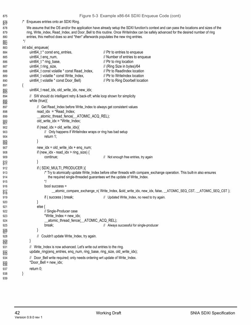
42 Working Draft SNIA SDXI Specification Version 0.9.0 rev 1
Figure 5-3 Example x86-64 SDXI Enqueue Code (cont) 875
/* Enqueues entries onto an SDXI Ring. 876 877
We assume that the OS and/or the application have already setup the SDXI function's context and can pass the locations and sizes of the 878 ring, Write_index, Read_Index, and Door_Bell to this routine. Once WriteIndex can be safely advanced for the desired number of ring 879 entries, this method does so and *then* afterwards populates the new ring entries. 880
*/ 881 882 int sdxi_enqueue( 883 uint64_t * const enq_entries, // Ptr to entries to enqueue 884 uint64_t enq_num, // Number of entries to enqueue 885 uint64_t * ring_base, // Ptr to ring location 886 uint64_t ring_size, // (Ring Size in bytes)/64 887 uint64_t const volatile * const Read_Index, // Ptr to ReadIndex location 888 uint64_t volatile * const Write_Index, // Ptr to WriteIndex location 889 uint64_t volatile * const Door_Bell) // Ptr to Ring Doorbell location 890 { 891 uint64_t read_idx, old_write_idx, new_idx; 892 893
// SW should do intelligent retry & back-off; while loop shown for simplicity 894 while (true){ 895 896
// Get Read_Index before Write_Index to always get consistent values 897 read_idx = *Read_Index; 898 __atomic_thread_fence(__ATOMIC_ACQ_REL); 899 old_write_idx = *Write_Index; 900 901 if (read_idx > old_write_idx){ 902
// Only happens if WriteIndex wraps or ring has bad setup 903 return 1; 904 } 905 906 new_idx = old_write_idx + enq_num; 907 if (new_idx - read_idx > ring_size) { 908 continue; // Not enough free entries, try again 909 } 910 911 if ( SDXI_MULTI_PRODUCER ){ 912 /* Try to atomically update Write_Index before other threads with compare_exchange operation. This built-in also ensures 913
the required single-threaded guarantees wrt the update of Write_Index. 914 */ 915 bool success = 916 __atomic_compare_exchange_n( Write_Index, &old_write_idx, new_idx, false, __ATOMIC_SEQ_CST, __ATOMIC_SEQ_CST ); 917 918 if ( success ) break; // Updated Write_Index, no need to try again. 919 } 920 else { 921
// Single-Producer case 922 *Write_Index = new_idx; 923 __atomic_thread_fence(__ATOMIC_ACQ_REL); 924 break; // Always successful for single-producer 925 } 926 927
// Couldn't update Write_Index, try again. 928 } 929 930
// Write_Index is now advanced. Let's write out entries to the ring. 931 update_ring(enq_entries, enq_num, ring_base, ring_size, old_write_idx); 932 933
// Door_Bell write required; only needs ordering wrt update of Write_Index. 934 *Door_Bell = new_idx; 935 936 return 0; 937 } 938
939

SNIA SDXI Specification Working Draft 43 Version 0.9.0 rev 1
Multi-Producer Enqueue 940
Multiple producer entities may use the enqueue procedure described in the prior section in parallel without 941 the use of locks or other higher-level serialization methods. While a context’s WriteIndex value in memory 942 must be monotonically increasing, the SDXI function may see doorbell writes to a context whose values 943 are not monotonically increasing. The function shall discard such doorbell writes. 944
945

44 Working Draft SNIA SDXI Specification Version 0.9.0 rev 1
5.2 Descriptor Processing 946
This section describes the specific behavior required of an SDXI function as it processes a descriptor. 947
The function processes descriptors from a ring using the following notional steps: 948
1. Determine space has been allocated in the descriptor ring (WriteIndex>ReadIndex), for example by 949 receiving a doorbell write with an updated WriteIndex value or by polling WriteIndex in memory. 950
2. Poll on the descriptor located at ReadIndex until it is valid. The function may stop polling after an 951 implementation-specific timeout period and log an error. 952
3. Check the Fence bit in the descriptor header. If it is set, wait for all prior descriptors within the same 953 context to complete. 954
4. Set the Valid field in the header to invalid. 955
5. Write incremented ReadIndex value back to memory. 956
6. Execute the descriptor operation including accessing any referenced AKeys and data buffers 957
7. Write an error log entry if an error was detected in any of the previous steps 958
8. Update MiscStatus in the Completion Status Block if necessary 959
9. Write an error log entry if any errors were encountered accessing the Completion Status Block 960
10. Complete the descriptor by atomically decrementing the completion signal in the Completion Status 961 Block, or if an error was previously detected, by writing all bits of the completion signal to 1. 962
11. Write an error log entry if any errors were encountered accessing the completion signal 963
964
If an error occurs during steps 1 to 3, an error log is written and processing for the current descriptor is 965 stopped. Further processing actions such as changing the Valid field or generating a completion signal are 966 not performed. 967
If an error occurs during steps 4, 5, or 6, the function jumps to step 7 and writes an error log entry. 968
If an error is detected during descriptor processing, the function starts transitioning the Context to the Error 969 state. All outstanding descriptors associated with the Context must complete prior to entering the Error 970 state. 971
Descriptor processing may be stopped during steps 1, 2 or 3 without logging an error. This may occur, for 972 example, due to the parallel execution of a Stop Context operation in an administrative context. Stopping 973 descriptor processing at any other time results in an error. 974
5.3 Descriptor Ordering and Parallel Execution 975
An SDXI function may prefetch any number of descriptors from a descriptor ring up to the location prior to 976 that indicated by the WriteIndex value in memory. Dynamic modification of valid descriptors located 977 between ReadIndex and WriteIndex-1 is not supported. 978
Following the model in the prior section, an SDXI function shall process descriptors in the order in which 979 they appear in the descriptor ring until the end of step 4 where the ReadIndex is incremented. An SDXI 980 function may execute steps 5 and later for multiple descriptors of the same context in parallel. 981
The Fence (F) flag may be used to constrain parallel execution. When the Fence flag is set, the function 982 shall wait for all prior descriptor operations to complete before executing the fenced descriptor operation. 983 When the Fence flag is clear, the descriptor operation may be executed while prior descriptor operations 984 are outstanding. 985

SNIA SDXI Specification Working Draft 45 Version 0.9.0 rev 1
The Sequential Consistency (S) flag may also affect parallel execution. See section 5.5 Memory 986 Consistency Model for more details. 987
There are no ordering or consistency requirements for descriptors belonging to different contexts. 988
5.4 Descriptor Completion 989
When each descriptor operation has completed, the function will decrement the referenced completion 990 signal in memory. Descriptors may complete out of order. It is up to software to assign completion signal 991 locations and initial values as appropriate. Some applications may require precise tracking of descriptors 992 while others may track groups of descriptors. 993
When a descriptor encounters an error during processing and causes its context to stop, there may be 994 multiple prior and/or subsequent descriptors from the same context being processed in parallel. These 995 may complete independently with or without error. 996
5.5 Memory Consistency Model 997
Unless otherwise specified, there are no ordering or consistency requirements between an SDXI function’s 998 memory accesses associated with the same descriptor operation. 999
An SDXI function clearing the descriptor header Valid bit shall be made globally visible ahead of making 1000 the ReadIndex update globally visible. Additionally, the clearing of the Valid bit shall be made globally 1001 visible ahead of making any writes associated the descriptor operation globally visible and ahead of 1002 making any writes to the descriptor’s Completion Status globally visible. 1003
All writes associated with a descriptor operation shall be made globally visible prior to making changes to 1004 the descriptor’s Completion Statusglobally visible. Within the Completion Status, changes to MiscStatus 1005 shall be made globally visible prior to making updates to the descriptor’s completion signal globally visible. 1006 Additionally, all error logs for the descriptor, other than those associated with accessing the completion 1007 status block shall be made globally visible prior to making updates to the completion status block globally 1008 visible. 1009
If the Sequential Consistency (S) flag is set, all writes from prior descriptor operations in the same context 1010 shall be made globally visible prior to making writes from the current descriptor operation globally visible, 1011 regardless of address. 1012
If the Sequential Consistency flag is clear, writes associated with the current descriptor operation may be 1013 reordered ahead of, and made globally visible prior to, writes associated with prior descriptor operations 1014 that have not yet been made globally visible. 1015
Unlike the fence flag, the sequential consistency flag allows multiple descriptors to be executed in parallel 1016 as long as the rules around global visibility are maintained. 1017
Developer Note: This note is regarding the use of Sequential Consistency Flag and PCIe Relaxed 1018 Ordering. 1019
In general, writes associated with a single descriptor operation may be issued over the PCIe bus in any 1020 order. 1021
If the S flag is clear, all writes associated with the descriptor operation may be issued as Relaxed Ordered 1022 (RO=1) writes. Additionally, writes associated with the descriptor operation may be issued ahead of writes 1023 associated with prior descriptor operations. 1024

46 Working Draft SNIA SDXI Specification Version 0.9.0 rev 1
If the S flag is set, all writes associated with a descriptor operation need to be issued as non-relaxed 1025 (RO=0) over the PCIe bus, and only after writes associated with all prior descriptor operations have been 1026 issued on the bus. 1027
5.6 Descriptor Chaining 1028
The descriptor chaining mechanism may be used for either Extended Descriptors or as part of the Error 1029 Log. See 5.6.1 Extended Descriptors and 3.4 Error Log for more details. 1030
A descriptor chain is formed from 2 or more adjacent 64-byte descriptor entries. Each entry in the chain is 1031 referred to as a link. Each link is formatted as a standard SDXI descriptor with an SDXI header and footer. 1032 Each link except for the last shall set the Chain (C) bit to 1 in their respective headers. The last link in the 1033 chain is indicated by a descriptor with the Chain bit clear. 1034
Software shall reserve enough space in the descriptor ring to enqueue the entire chain. The individual 1035 descriptor entries forming the chain may be written into the descriptor ring in arbitrary order. 1036
When processing a descriptor chain, an SDXI function shall increment ReadIndex by 1 and clear the 1037 header Valid bit for each link in the chain. 1038
Extended Descriptors 1039
Extended descriptors may be utilized by operations that require more than the 52 bytes of operand space 1040 provided by a single SDXI descriptor. Additional operand space may be created by chaining 2 or more 1041 descriptor entries. Each operation definition shall indicate whether the use of an extended descriptor is 1042 required. 1043
Other than the Chain bit, extended descriptors utilize the same descriptor header for each link in the chain. 1044
Only the last link in the chain contains a valid descriptor footer with the pointer to the completion status 1045 block. The descriptor footers for all other links in the chain are reserved. Only one completion signal 1046 decrement is performed for the entire extended descriptor. 1047
Error log entries are generated for the extended descriptor as a whole. 1048
An SDXI function processing an extended descriptor shall wait until all links are valid before executing the 1049 descriptor operation. 1050

SNIA SDXI Specification Working Draft 47 Version 0.9.0 rev 1
6 SDXI Descriptor and Operation Specification 1051
A set of related operations form an operations group. An operation requires a particular descriptor format 1052 to indicate parameters for the operation. These are described in this chapter. 1053
Table 6-1 SDXI Operation Groups, Types, and Subtypes 1054
Operation Group Type Subtype Operation (Reserved) 0x000 ‘-- ‘-- DMA Base Operation Group (DmaBaseGrp)
0x001 0x01 Nop 0x02 WriteImm 0x03 Copy 0x04 RepCopy
Administrative Operation Group (AdminGrp)
0x002 0x00 UpdateFunc 0x01 UpdateContext 0x02 UpdateAkey 0x03 Start 0x04 Stop 0x05 Intr 0x06 Sync
Atomic Operation Group (AtomicGrp)
0x003 0x00 Reserved 0x01 Swap 0x02 Unsigned Add 0x03 Unsigned Subtract 0x04 Reserved 0x05 AND 0x06 OR 0x07 XOR 0x08 Signed Min 0x09 Signed Max 0x0A Unsigned Clamping Increment 0x0B Unsigned Clamping Decrement 0x0C Compare and Swap
Interrupt Operation Group (IntrGrp) 0x004 0x00 Interrupt Connection Operation Group (ConnectGrp)
0x005 ‘-- Reserved
Reserved 0x7F6 – 0x006 ‘-- ‘-- Reserved for Error Log 0x7F7 ‘-- ‘-- Vendor Defined 0x7F8 – 0x7FF ‘-- Reserved
1055 Operation Types and Subtypes are encoded in the first 4-bytes of the descriptor header as: 1056
Figure 6-1 Type & Subtype Encoding in Descriptors 1057
1058
31 30 29 28 27 26 25 24 23 22 21 20 19 18 17 16 15 14 13 12 11 10 9 8 7 6 5 4 3 2 1 0
DWORD00 CH FE SE VL
* * * * 0000 00000
< - - opcode - - > subtype type
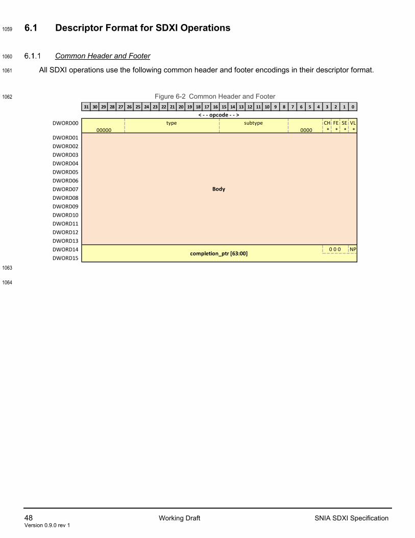
48 Working Draft SNIA SDXI Specification Version 0.9.0 rev 1
6.1 Descriptor Format for SDXI Operations 1059
Common Header and Footer 1060
All SDXI operations use the following common header and footer encodings in their descriptor format. 1061
Figure 6-2 Common Header and Footer 1062
1063
1064
31 30 29 28 27 26 25 24 23 22 21 20 19 18 17 16 15 14 13 12 11 10 9 8 7 6 5 4 3 2 1 0
DWORD00 CH FE SE VL
* * * *DWORD01DWORD02DWORD03DWORD04DWORD05DWORD06DWORD07DWORD08DWORD09DWORD10DWORD11DWORD12DWORD13DWORD14 NP
DWORD150 0 0
completion_ptr [63:00]
0000 00000
Body
< - - opcode - - > subtype type

SNIA SDXI Specification Working Draft 49 Version 0.9.0 rev 1
<!-- Table=Desc --!> 1065 Table 6-2 SDXI Operation Common Header and Footer Descriptor Format 1066
Location Field Bit Range Description DW00[31:00] ‘opcode:' 031:000 Opcode
DW00[00] ‘valid =* (VL)’ 000 1 = Descriptor is valid. All fields may be processed. 0 = Descriptor is invalid. All other fields within the descriptor shall be ignored. The function shall poll the descriptor until it becomes valid or until an implementation defined timeout period has expired at which point an error is logged.
DW00[01] ‘sequential = * (SE)’ 001 Sequential Consistency 1 = Operation writes are sequentially consistent 0 = Operation writes are not required to be sequentially consistent See section 5.5 for more details.
DW00[02] ‘fence =* (FE)’ 002 1 = All prior descriptor operations shall complete before executing this descriptor’s operation 0 = Execution of this descriptor’s operation is permitted prior to the completion of prior descriptor operations See section 5.3 for more details.
DW00[03] ‘chain = * (CH)’ 003 Chain. 1=Start or middle of a set of chained descriptors. 0=End of chain, or non-chained descriptor. See section 5.6 for more details.
DW00[07:04] ‘= 0000’ 007:004 Shall be set to 0 DW00[15:08] ‘subtype’ 015:008 Specifies an operation within the Operation Group. DW00[26:16] ‘type’ 026:016 Specifies the Operation Group. DW00[31:27] ‘= 00000’ 031:027 Shall be set to 0
DW13:01 ‘Operation’ 447:032 This region is defined separately for each operation.
DW15:14 ‘completion_ptr [63:00]^’ 511:448 A pointer to a 16B aligned region of memory containing the Completion Status block. An invalid pointer may result in an error.
DW14[00] ‘no_pointer (NP)’ 448 When 0, the SDXI function shall update the completion status blocked pointed to by completion_ptr. When 1, there is no completion status block associated with the descriptor to update and the completion_ptr shall be ignored. This mechanism avoids the overhead of completion-block-status processing for a series of descriptor requests that are ordered before a terminal one which will specify a completion status block.
DW14[03:01] ‘0 0 0~’ 451:449 Shall be set to 0 1067
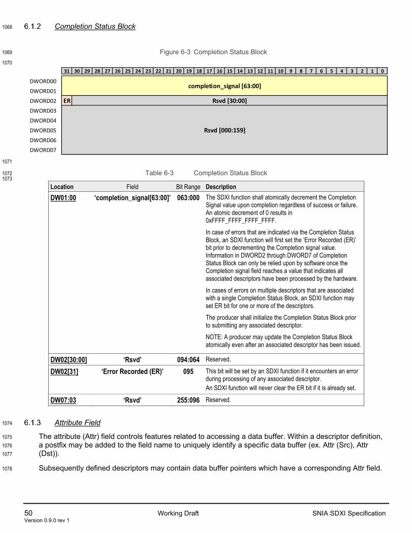
50 Working Draft SNIA SDXI Specification Version 0.9.0 rev 1
Completion Status Block 1068
Figure 6-3 Completion Status Block 1069
1070
1071
Table 6-3 Completion Status Block 1072 1073
Location Field Bit Range Description DW01:00 ‘completion_signal[63:00]’ 063:000 The SDXI function shall atomically decrement the Completion
Signal value upon completion regardless of success or failure. An atomic decrement of 0 results in 0xFFFF_FFFF_FFFF_FFFF.
In case of errors that are indicated via the Completion Status Block, an SDXI function will first set the ‘Error Recorded (ER)’ bit prior to decrementing the Completion signal value. Information in DWORD2 through DWORD7 of Completion Status Block can only be relied upon by software once the Completion signal field reaches a value that indicates all associated descriptors have been processed by the hardware.
In cases of errors on multiple descriptors that are associated with a single Completion Status Block, an SDXI function may set ER bit for one or more of the descriptors.
The producer shall initialize the Completion Status Block prior to submitting any associated descriptor.
NOTE: A producer may update the Completion Status Block atomically even after an associated descriptor has been issued.
DW02[30:00] ‘Rsvd’ 094:064 Reserved.
DW02[31] ‘Error Recorded (ER)’ 095 This bit will be set by an SDXI function if it encounters an error during processing of any associated descriptor. An SDXI function will never clear the ER bit if it is already set.
DW07:03 ‘Rsvd’ 255:096 Reserved.
Attribute Field 1074
The attribute (Attr) field controls features related to accessing a data buffer. Within a descriptor definition, 1075 a postfix may be added to the field name to uniquely identify a specific data buffer (ex. Attr (Src), Attr 1076 (Dst)). 1077
Subsequently defined descriptors may contain data buffer pointers which have a corresponding Attr field. 1078
31 30 29 28 27 26 25 24 23 22 21 20 19 18 17 16 15 14 13 12 11 10 9 8 7 6 5 4 3 2 1 0
DWORD00
DWORD01
DWORD02 ERDWORD03
DWORD04
DWORD05
DWORD06
DWORD07
Rsvd [000:159]
completion_signal [63:00]
Rsvd [30:00]

SNIA SDXI Specification Working Draft 51 Version 0.9.0 rev 1
Table 6-4 Attribute Field 1079
Bits Field Description
1:0 CoherencyControl 00b : The associated memory location is accessed as I/O coherent. 01b : The associated memory location is accessed as non-coherent. 10b : The associated memory location is accessed as I/O coherent. Cache injection may be used for the associated data buffer if enabled. All other encodings reserved
2 Reserved Shall be set to 0
3 MMIO 1b: The referenced memory buffer may be located in either system memory or MMIO space. 0b: The reference memory buffer is located in system memory and is not located in an MMIO space. This setting may optimize performance in some implementations.
1080
Figure 6-4 AttributeFormat 1081
1082
3 2 1:0MMIO rsvd Coherency Ctl

52 Working Draft SNIA SDXI Specification Version 0.9.0 rev 1
6.2 DMA Base Operations Group (DmaBaseGrp) 1083
All SDXI implementations are required to support the DmaBaseGrp operations. 1084
DmaBaseGrp: DS_DMAB_NOP 1085
The DmaBaseGrp’s Nop operation performs no functional DMA operation. A descriptor specifying the 1086 operation is processed and ordered the same as other descriptors, obeys all relevant bits in the header, 1087 and generates the completion signal. 1088
Figure 6-5 DS_DMAB_NOP Descriptor Format 1089
1090
1091
31 30 29 28 27 26 25 24 23 22 21 20 19 18 17 16 15 14 13 12 11 10 9 8 7 6 5 4 3 2 1 0
DWORD00 CH FE SE VL
0 * 0 1DWORD01DWORD02DWORD03DWORD04DWORD05DWORD06DWORD07DWORD08DWORD09DWORD10DWORD11DWORD12DWORD13DWORD14 NP
DWORD150 0 0
completion_ptr [63:00]
0000 0x01 0x001 00000
rsvd (r)
< - - opcode - - > subtype type

SNIA SDXI Specification Working Draft 53 Version 0.9.0 rev 1
<!-- Table=Desc --!> 1092 Table 6-5 DS_DMAB_NOP Descriptor Format 1093
Location Field Bit Range Description DW00[31:00] ‘opcode:' 031:000 Opcode
DW00[00] ‘valid =1 (VL)’ 000 See header description. DW00[01] ‘sequential = 0 (SE)’ 001 Shall be set to 0. DW00[02] ‘fence = * (FE)’ 002 See header description. DW00[03] ‘chain=0 (CH)’ 003 Shall be set to 0. DW00[07:04] ‘= 0000’ 007:004 Shall be set to 0 DW00[15:08] ‘subtype=0x01’ 015:008 See header description. DW00[26:16] ‘type=0x001’ 026:016 See header description. DW00[31:27] ‘= 00000’ 031:027 Shall be set to 0
DW13:01 ‘rsvd (r)’ 447:032 Shall be set to 0
DW15:14 ‘completion_ptr [63:00]^’ 511:448 See footer description, Section 6.1.1
DW14[00] ‘no_pointer (NP)’ 448 See footer description, Section 6.1.1 DW14[03:01] ‘0 0 0~’ 451:449 Shall be set to 0
<!-- Table=End --!> 1094 1095

54 Working Draft SNIA SDXI Specification Version 0.9.0 rev 1
DmaBaseGrp: DS_DMAB_WRT_IMM Operation 1096
The DmaBaseGrp’s WriteImm operation is used to write up to 32 contiguous bytes starting at a destination 1097 memory address. The data is supplied inside the descriptor. Following little-endian conventions, data byte 1098 0 is written to the first byte of the destination address. Write atomicity guarantees are implementation 1099 specific. 1100
Figure 6-6 DS_DMAB_WRT_IMM Descriptor Format 1101
1102
1103
31 30 29 28 27 26 25 24 23 22 21 20 19 18 17 16 15 14 13 12 11 10 9 8 7 6 5 4 3 2 1 0
DWORD00 CH FE SE VL
0 * * 1
DWORD01
DWORD02DWORD03DWORD04DWORD05DWORD06DWORD07DWORD08DWORD09DWORD10DWORD11DWORD12DWORD13DWORD14 NP
DWORD15
akey0 (Dst)rsvd (r)
address0 [63:00] (Dst)
data [255:000]
0 0 0 completion_ptr [63:00]
bsize 0 0 0 rsvd (r)< - - attr - - >
attr0 (Dst)rsvd (r) rsvd (r)
0000 0x02 0x001 00000< - - size - - >
< - - opcode - - > subtype type

SNIA SDXI Specification Working Draft 55 Version 0.9.0 rev 1
<!-- Table=Desc --!> 1104 Table 6-6 DS_DMAB_WRT_IMM Descriptor Format 1105
Location Field Bit Range Description DW00[31:00] ‘opcode:' 031:000 Opcode
DW00[00] ‘valid =1 (VL)’ 000 See header description. DW00[01] ‘sequential = * (SE)’ 001 See header description. DW00[02] ‘fence = * (FE)’ 002 See header description. DW00[03] ‘chain=0 (CH)’ 003 Shall be set to 0. DW00[07:04] ‘= 0000’ 007:004 Shall be set to 0 DW00[15:08] ‘subtype=0x02’ 015:008 See header description. DW00[26:16] ‘type=0x001’ 026:016 See header description. DW00[31:27] ‘= 00000’ 031:027 Shall be set to 0
DW01[07:00] ‘size*' 039:032 Size DW01[04:00] ‘bsize’ 036:032 Specifies the number of bytes to write minus 1.
0x0 = 1 Byte, . . .0x1F = 32 Bytes DW01[07:05] ‘0 0 0’ 039:037 Shall be set to 0
DW01[31:08] ‘rsvd (r)’ 063:040 Shall be set to 0
DW02[07:00] ‘attr*' 071:064 Attributes DW02[03:00] ‘attr0 (Dst)’ 067:064 Destination buffer attributes DW02[07:04] ‘rsvd (r)’ 071:068 Shall be set to 0
DW02[31:08] ‘rsvd (r)’ 095:072 Shall be set to 0 DW03[15:00] ‘akey0 (Dst)’ 111:096 Destination buffer AKey DW03[31:16] ‘rsvd (r)’ 127:112 Shall be set to 0 DW05:04 ‘address0 [63:00] (Dst)’ 191:128 Starting Destination Buffer Address
DW13:06 ‘data [255:000]’ 447:192 Immediate Data DW15:14 ‘completion_ptr [63:00]^’ 511:448 See footer description, Section 6.1.1
DW14[00] ‘no_pointer (NP)’ 448 See footer description, Section 6.1.1 DW14[03:01] ‘0 0 0~’ 451:449 Shall be set to 0
<!-- Table=End --!> 1106

56 Working Draft SNIA SDXI Specification Version 0.9.0 rev 1
DmaBaseGrp: DS_DMAB_COPY Operation 1107
The DmaBaseGrp’s Copy operation copies a source data buffer to a destination data buffer. 1108
It is an error (Generic Descriptor Error/Unsupported Field Encoding) for the source and destination buffers 1109 to exceed the size described by CL1TE.MaxBuffer. 1110
Figure 6-7 DS_DMAB_COPY Descriptor Format 1111
1112
1113
31 30 29 28 27 26 25 24 23 22 21 20 19 18 17 16 15 14 13 12 11 10 9 8 7 6 5 4 3 2 1 0
DWORD00 CH FE SE VL
0 * * 1DWORD01
DWORD02DWORD03DWORD04DWORD05DWORD06DWORD07DWORD08DWORD09DWORD10DWORD11DWORD12DWORD13DWORD14 NP
DWORD15
address0 [63:00] (Src)
address1 [63:00] (Dst)
rsvd (r)
0 0 0 completion_ptr [63:00]
< - - attr - - > attr0 (Src)attr1 (Dst) rsvd (r)
akey0 (Src)akey1 (Dst)
0000 0x03 0x001 00000size
< - - opcode - - > subtype type

SNIA SDXI Specification Working Draft 57 Version 0.9.0 rev 1
<!-- Table=Desc --!> 1114 Table 6-7 DS_DMAB_ COPY Descriptor Format 1115
Location Field Bit Range Description DW00[31:00] ‘opcode:' 031:000 Opcode
DW00[00] ‘valid =1 (VL)’ 000 See header description. DW00[01] ‘sequential = * (SE)’ 001 See header description. DW00[02] ‘fence = * (FE)’ 002 See header description. DW00[03] ‘chain=0 (CH)’ 003 Shall be set to 0. DW00[07:04] ‘= 0000’ 007:004 Shall be set to 0 DW00[15:08] ‘subtype=0x03’ 015:008 See header description. DW00[26:16] ‘type=0x001’ 026:016 See header description. DW00[31:27] ‘= 00000’ 031:027 Shall be set to 0
DW01[31:00] ‘size’ 063:032 Specifies the number of bytes to write minus 1. 0x0 = 1 Byte, . . ., 0xFFFF_FFFF = 2**32 Bytes
DW02[07:00] ‘attr*' 071:064 Attributes DW02[03:00] ‘attr0 (Src)’ 067:064 Source buffer attributes DW02[07:04] ‘attr1 (Dst)’ 071:068 Destination buffer attributes
DW02[31:08] ‘rsvd (r)’ 095:072 Shall be set to 0
DW03[15:00] ‘akey0 (Src)’ 111:096 Source buffer AKey
DW03[31:16] ‘akey1 (Dst)’ 127:112 Destination buffer AKey
DW05:04 ‘address0 [63:00] (Src)’ 191:128 Source Buffer Address
DW07:06 ‘address1 [63:00] (Dst)’ 255:192 Destination Buffer Address
DW13:08 ‘rsvd (r)’ 447:256 Shall be set to 0
DW15:14 ‘completion_ptr [63:00]^’ 511:448 See footer description, Section 6.1.1 DW14[00] ‘no_pointer (NP)’ 448 See footer description, Section 6.1.1 DW14[03:01] ‘0 0 0~’ 451:449 Shall be set to 0
<!-- Table=End --!> 1116

58 Working Draft SNIA SDXI Specification Version 0.9.0 rev 1
DmaBaseGrp: DS_DMAB_REPCOPY Operation 1117
The DmaBaseGrp’s Repeat Copy operation copies a single 4-KiB-aligned source data buffer to multiple 1118 adjacent locations within a 4-KiB-aligned destination buffer. This operation may be used, for example, to 1119 fill a large region of memory. 1120
It is an error (Generic Descriptor Error/Unsupported Field Encoding) to specify a destination buffer size 1121 greater than the size described by CL1TE..MaxBuffer. 1122
Figure 6-8 DS_DMAB_REPCOPY Descriptor Format 1123
1124
1125
31 30 29 28 27 26 25 24 23 22 21 20 19 18 17 16 15 14 13 12 11 10 9 8 7 6 5 4 3 2 1 0
DWORD00 CH FE SE VL
0 * * 1
DWORD01
DWORD02DWORD03DWORD04 AZ
DWORD05DWORD06DWORD07
DWORD08DWORD09DWORD10DWORD11DWORD12DWORD13DWORD14 NP
DWORD15
rsvd (r)
0 0 0 completion_ptr [63:00]
0 … 0 address1 [63:00] (Dst)
< - - repeat - - > 0 . . . 0 number
akey0 (Src)akey1 (Dst)0 … 0
address0 [63:00] (Src)
0 … 0 nsize 0 … 0 < - - attr - - >
attr0 (Src)attr1 (Dst) rsvd (r)
0000 0x04 0x001 00000< - - size - - >
< - - opcode - - > subtype type

SNIA SDXI Specification Working Draft 59 Version 0.9.0 rev 1
<!-- Table=Desc --!> 1126 Table 6-8 DS_DMAB_REPCOPY Descriptor Format 1127
Location Field Bit Range Description DW00[31:00] ‘opcode:' 031:000 Opcode
DW00[00] ‘valid =1 (VL)’ 000 See header description. DW00[01] ‘sequential = * (SE)’ 001 See header description. DW00[02] ‘fence = * (FE)’ 002 See header description. DW00[03] ‘chain=0 (CH)’ 003 Shall be set to 0. DW00[07:04] ‘= 0000’ 007:004 Shall be set to 0 DW00[15:08] ‘subtype=0x04’ 015:008 See header description. DW00[26:16] ‘type=0x001’ 026:016 See header description. DW00[31:27] ‘= 00000’ 031:027 Shall be set to 0
DW01[31:00] ‘size*' 063:032 Size DW01[11:00] ‘0 … 0’ 043:032 Shall be set to 0
DW01[20:12] ‘nsize’ 052:044 The size of the source data buffer in 4-Kbyte increments minus 1. 0x0 = 4 Kbytes, … , 0x1FF = 2 Mbytes
DW01[31:21] ‘0 … 0’ 063:053 Shall be set to 0
DW02[07:00] ‘attr*' 071:064 Attribute Fields DW02[03:00] ‘attr0 (Src)’ 067:064 Source buffer attributes DW02[07:04] ‘attr1 (Dst)’ 071:068 Destination buffer attributes
DW02[31:08] ‘rsvd (r)' 095:072 Shall be set to 0 DW03[15:00] ‘akey0 (Src)’ 111:096 Source buffer AKey DW03[31:16] ‘akey1 (Dst)’ 127:112 Destination buffer AKey DW05:04 ‘address0 [63:00] (Src)^’ 191:128 4KB aligned source buffer starting address.
DW04[00] ‘all_zero (AZ)’ 128
When AZ=1, this indicates that the source buffer is all zero. This allows the SDXI function to optimize the transfer (even avoiding reading the buffer). When AZ=0, no such guarantee is made. When AZ=1, SW shall always initialize the entire source buffer to zero; otherwise the contents of the destination is not defined – and no error is required to be reported in this case.
DW04[11:01] ‘0 … 0~’ 139:129 Shall be set to 0 DW07:06 ‘address1 [63:00] (Dst)^’ 255:192 4KB aligned destination buffer starting address.
DW06[11:00] ‘0 … 0~’ 203:192 Shall be set to 0 DW08[31:00] ‘repeat*’ 287:256 Specifies the number of times the source data buffer is copied
to the destination buffer. 0x0 = 1 copy …. 0xF_FFFF = 220 copies. The total destination size is: 4Kbytes * (Size+1) * (Repeat+1).
DW08[11:00] ‘0 . . . 0’ 267:256 Shall be set to 0 DW08[31:12] ‘number’ 287:268 See above
DW13:09 ‘rsvd (r)’ 447:288 Shall be set to 0 DW15:14 ‘completion_ptr [63:00]^’ 511:448 See footer description, Section 6.1.1
DW14[00] ‘no_pointer (NP)’ 448 See footer description, Section 6.1.1 DW14[03:01] ‘0 0 0~’ 451:449 Shall be set to 0
<!-- Table=End --!> 1128

60 Working Draft SNIA SDXI Specification Version 0.9.0 rev 1
6.3 Administrative Operation Group (AdminGrp) 1129
Administrative operations are used by software to manage the SDXI function. 1130
AdminGrp’s Update operations are part of the administrative operations group. They are used by 1131 privileged software to indicate changes to various memory data structures. When an Update operation 1132 signals completion, this does not guarantee that the effects of the operation are visible or that the flushing 1133 of any affected caches has completed. 1134
Update operations shall be used even when transitioning data structures from the invalid to valid state. 1135 This is done to simplify software emulated implementations. 1136
The AdminGrp’s Sync operation is used as a barrier after one or more Update operations. After 1137 completion of the Sync, the effects of prior AdminGrp Updates to the structures selected by the Sync 1138 operation are guaranteed to be seen by all new descriptors. AdminGrp’s Sync does not act as a barrier for 1139 AdminGrp Update operations executed in different contexts from the Sync. 1140
The AdminGrp’s Start and Stop operations may be used to control the execution state of a target context. 1141 A context that is stopped may also be started by writing appropriate memory state values followed by 1142 writing an appropriate doorbell. 1143
See section 7.2 for more details. 1144
1145
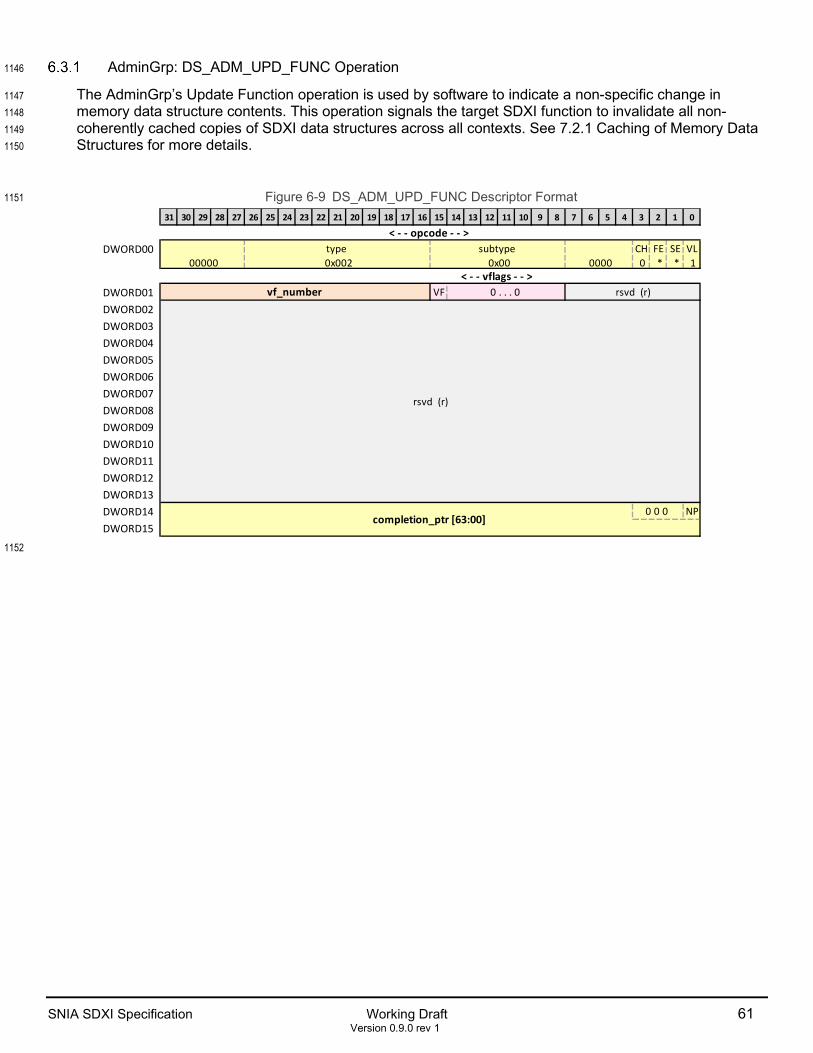
SNIA SDXI Specification Working Draft 61 Version 0.9.0 rev 1
AdminGrp: DS_ADM_UPD_FUNC Operation 1146
The AdminGrp’s Update Function operation is used by software to indicate a non-specific change in 1147 memory data structure contents. This operation signals the target SDXI function to invalidate all non-1148 coherently cached copies of SDXI data structures across all contexts. See 7.2.1 Caching of Memory Data 1149 Structures for more details. 1150
Figure 6-9 DS_ADM_UPD_FUNC Descriptor Format 1151
1152
31 30 29 28 27 26 25 24 23 22 21 20 19 18 17 16 15 14 13 12 11 10 9 8 7 6 5 4 3 2 1 0
DWORD00 CH FE SE VL
0 * * 1
DWORD01 VF
DWORD02DWORD03DWORD04DWORD05DWORD06DWORD07DWORD08DWORD09DWORD10DWORD11DWORD12DWORD13DWORD14 NP
DWORD15
rsvd (r)0 . . . 0 vf_number
rsvd (r)
0 0 0 completion_ptr [63:00]
0000 0x00 0x002 00000< - - vflags - - >
< - - opcode - - > subtype type

62 Working Draft SNIA SDXI Specification Version 0.9.0 rev 1
<!-- Table=Desc --!> 1153 Table 6-9 DS_ADM_UPD_FUNC Operation Descriptor Format 1154
Location Field Bit Range Description DW00[31:00] ‘opcode:' 031:000 Opcode
DW00[00] ‘valid =1 (VL)’ 000 See header description. DW00[01] ‘sequential = * (SE)’ 001 See header description. DW00[02] ‘fence = * (FE)’ 002 See header description. DW00[03] ‘chain=0 (CH)’ 003 Shall be set to 0. DW00[07:04] ‘= 0000’ 007:004 Shall be set to 0 DW00[15:08] ‘subtype=0x00’ 015:008 See header description. DW00[26:16] ‘type=0x002’ 026:016 See header description. DW00[31:27] ‘= 00000’ 031:027 Shall be set to 0
DW01[07:00] ‘rsvd (r)’ 039:032 Shall be set to 0
DW01[15:08] ‘vflags*' 048:040 Flags
DW01[14:08] ‘0 . . . 0’ 046:040 Shall be set to 0 DW01[15] ‘vf_valid (VF)’ 047 1 = Update the VF number indicated by vf_number
0 = Update within the local function context executing this descriptor (For VF administrative contexts, this field shall be set to 0.)
DW01[31:16] ‘vf_number’ 063:048 Only valid for PF administrative contexts. When VF=1, this field
indicates the VF to update. (For VF administrative contexts, this field shall be set to 0.)
DW13:02 ‘rsvd (r)’ 447:096 Shall be set to 0 DW15:14 ‘completion_ptr [63:00]^’ 511:448 See footer description, Section 6.1.1
DW14[00] ‘no_pointer (NP)’ 448 See footer description, Section 6.1.1 DW14[03:01] ‘0 0 0~’ 451:449 Shall be set to 0
<!-- Table=End --!> 1155
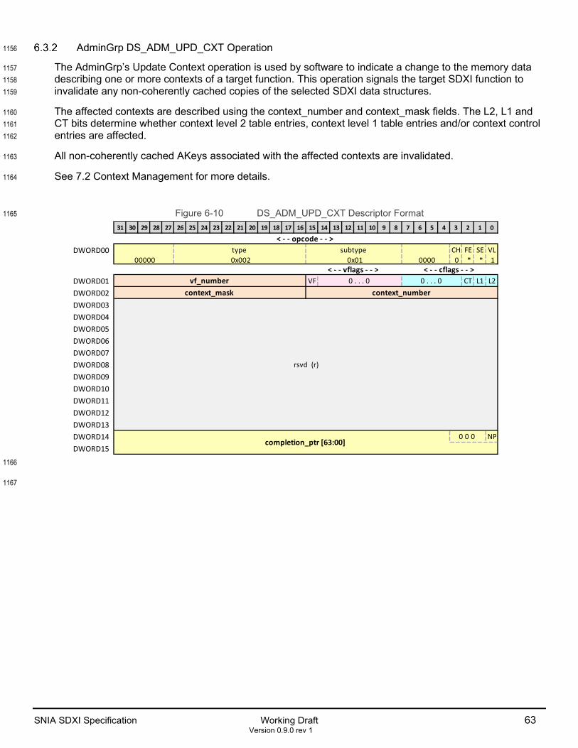
SNIA SDXI Specification Working Draft 63 Version 0.9.0 rev 1
AdminGrp DS_ADM_UPD_CXT Operation 1156
The AdminGrp’s Update Context operation is used by software to indicate a change to the memory data 1157 describing one or more contexts of a target function. This operation signals the target SDXI function to 1158 invalidate any non-coherently cached copies of the selected SDXI data structures. 1159
The affected contexts are described using the context_number and context_mask fields. The L2, L1 and 1160 CT bits determine whether context level 2 table entries, context level 1 table entries and/or context control 1161 entries are affected. 1162
All non-coherently cached AKeys associated with the affected contexts are invalidated. 1163
See 7.2 Context Management for more details. 1164
Figure 6-10 DS_ADM_UPD_CXT Descriptor Format 1165
1166
1167
31 30 29 28 27 26 25 24 23 22 21 20 19 18 17 16 15 14 13 12 11 10 9 8 7 6 5 4 3 2 1 0
DWORD00 CH FE SE VL
0 * * 1
DWORD01 VF CT L1 L2
DWORD02DWORD03DWORD04DWORD05DWORD06DWORD07DWORD08DWORD09DWORD10DWORD11DWORD12DWORD13DWORD14 NP
DWORD15
rsvd (r)
0 0 0 completion_ptr [63:00]
0 . . . 0 0 . . . 0 vf_number context_number context_mask
0000 0x01 0x002 00000< - - cflags - - > < - - vflags - - >
< - - opcode - - > subtype type

64 Working Draft SNIA SDXI Specification Version 0.9.0 rev 1
<!-- Table=Desc --!> 1168 Table 6-10 DS_ADM_UPD_CXT Descriptor Format 1169
Location Field Bit Range Description DW00[31:00] ‘opcode:' 031:000 Opcode
DW00[00] ‘valid =1 (VL)’ 000 See header description. DW00[01] ‘sequential = * (SE)’ 001 See header description. DW00[02] ‘fence = * (FE)’ 002 See header description. DW00[03] ‘chain=0 (CH)’ 003 Shall be set to 0. DW00[07:04] ‘= 0000’ 007:004 Shall be set to 0 DW00[15:08] ‘subtype=0x01’ 015:008 See header description. DW00[26:16] ‘type=0x002’ 026:016 See header description. DW00[31:27] ‘= 00000’ 031:027 Shall be set to 0
DW01[07:00] ‘cflags*' 039:032 Flags DW01[00] ‘CLT2(L2)’ 032 When 1, indicates that context level 2 table entries associated
with the masked context_number have been updated DW01[01] ‘CLT1(L1)’ 033 When 1, indicates that context level 1 table entries associated
with the masked context_number have been updated DW01[02] ‘CCE(CT)’ 034 When 1, indicates that the context control entries specified by the
masked context_number have been updated DW01[07:03] ‘0 . . . 0’ 039:035 Shall be set to 0
DW01[15:08] ‘vflags*' 047:040 Flags DW01[14:08] ‘0 . . . 0’ 046:040 Shall be set to 0 DW01[15] ‘vf_valid (VF)’ 047 1 = Update the VF number indicated by vf_number
0 = Update within the local function context executing this descriptor (For VF administrative contexts, this field shall be set to 0.)
DW01[31:16] ‘vf_number’ 063:048 Only valid for PF administrative contexts. When VF=1, this field indicates the VF to update. (For VF administrative contexts, this field shall be set to 0.)
DW02[15:00] ‘context_number’ 079:064 Indicates the context number to start. This value is masked by context_mask.
DW02[31:16] ‘context_mask’ 095:080 For each bit in context_mask that is set to 1, the corresponding bit in context_number is ignored when matching cached Context entries. When invalidating Context Level 2 Table Entries, aligned blocks of 128 context numbers must be updated using context_mask.
DW13:03 ‘rsvd (r)’ 447:096 Shall be set to 0 DW15:14 ‘completion_ptr [63:00]^’ 511:448 See footer description, Section 6.1.1
DW14[00] ‘no_pointer (NP)’ 448 See footer description, Section 6.1.1 DW14[03:01] ‘0 0 0~’ 451:449 Shall be set to 0
<!-- Table=End --!> 1170 1171
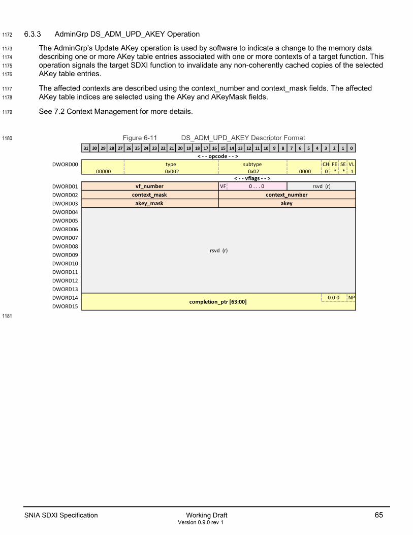
SNIA SDXI Specification Working Draft 65 Version 0.9.0 rev 1
AdminGrp DS_ADM_UPD_AKEY Operation 1172
The AdminGrp’s Update AKey operation is used by software to indicate a change to the memory data 1173 describing one or more AKey table entries associated with one or more contexts of a target function. This 1174 operation signals the target SDXI function to invalidate any non-coherently cached copies of the selected 1175 AKey table entries. 1176
The affected contexts are described using the context_number and context_mask fields. The affected 1177 AKey table indices are selected using the AKey and AKeyMask fields. 1178
See 7.2 Context Management for more details. 1179
Figure 6-11 DS_ADM_UPD_AKEY Descriptor Format 1180
1181
31 30 29 28 27 26 25 24 23 22 21 20 19 18 17 16 15 14 13 12 11 10 9 8 7 6 5 4 3 2 1 0
DWORD00 CH FE SE VL
0 * * 1
DWORD01 VF
DWORD02DWORD03DWORD04DWORD05DWORD06DWORD07DWORD08DWORD09DWORD10DWORD11DWORD12DWORD13DWORD14 NP
DWORD15
akey akey_mask
rsvd (r)
0 0 0 completion_ptr [63:00]
rsvd (r)0 . . . 0 vf_number context_number context_mask
0000 0x02 0x002 00000< - - vflags - - >
< - - opcode - - > subtype type

66 Working Draft SNIA SDXI Specification Version 0.9.0 rev 1
<!-- Table=Desc --!> 1182 Table 6-11 DS_ADM_UPD_AKEY Descriptor Format 1183
Location Field Bit Range Description DW00[31:00] ‘opcode:' 031:000 Opcode
DW00[00] ‘valid =1 (VL)’ 000 See header description. DW00[01] ‘sequential = * (SE)’ 001 See header description. DW00[02] ‘fence = * (FE)’ 002 See header description. DW00[03] ‘chain=0 (CH)’ 003 Shall be set to 0. DW00[07:04] ‘= 0000’ 007:004 Shall be set to 0 DW00[15:08] ‘subtype=0x02’ 015:008 See header description. DW00[26:16] ‘type=0x002’ 026:016 See header description. DW00[31:27] ‘= 00000’ 031:027 Shall be set to 0
DW01[07:00] ‘rsvd (r)’ 039:032 Shall be set to 0
DW01[15:08] ‘vflags*' 047:040 Flags DW01[14:08] ‘0 . . . 0’ 046:040 Shall be set to 0 DW01[15] ‘vf_valid (VF)’ 047 1 = Update the VF number indicated by vf_number
0 = Update within the local function context executing this descriptor (For VF administrative contexts, this field shall be set to 0.)
DW01[31:16] ‘vf_number’ 063:048 Only valid for PF administrative contexts. When VF=1, this field indicates the VF to update. (For VF administrative contexts, this field shall be set to 0.)
DW02[15:00] ‘context_number’ 079:064 Indicates the context number to start. This value is masked by context_mask.
DW02[31:16] ‘context_mask’ 095:080 For each bit in context_mask that is set to 1, the corresponding bit in context_number is ignored when matching cached Context entries. When invalidating Context Level 2 Table Entries, aligned blocks of 128 context numbers must be updated using context_mask.
DW03[15:00] ‘akey’ 111:096 When combined with akey_mask, indicates the AKey values that have been updated.
DW03[31:16] ‘akey_mask’ 127:112 For each bit in akey_mask that is set to 1, the corresponding bit in AKey is ignored when matching cached AKey entries numbers
DW13:04 ‘rsvd (r)’ 447:128 Shall be set to 0 DW15:14 ‘completion_ptr [63:00]^’ 511:448 See footer description, Section 6.1.1
DW14[00] ‘no_pointer (NP)’ 448 See footer description, Section 6.1.1 DW14[03:01] ‘0 0 0~’ 451:449 Shall be set to 0
<!-- Table=End --!> 1184

SNIA SDXI Specification Working Draft 67 Version 0.9.0 rev 1
AdminGrp DS_ADM_START Operation 1185
The AdminGrp’s Start operation: changes the value of ContextState within the target context’s Context 1186 Status Entry to indicate Running; and signals the context to run using the supplied doorbell value. 1187
Figure 6-12 DS_ADM_START Descriptor Format 1188
1189
1190
31 30 29 28 27 26 25 24 23 22 21 20 19 18 17 16 15 14 13 12 11 10 9 8 7 6 5 4 3 2 1 0
DWORD00 CH FE SE VL
0 1 * 1
DWORD01 VF DR
DWORD02DWORD03DWORD04DWORD05DWORD06DWORD07DWORD08DWORD09DWORD10DWORD11DWORD12DWORD13DWORD14 NP
DWORD15
rsvd (r)
doorbell [63:00]
rsvd (r)
0 0 0 completion_ptr [63:00]
rsvd (r)0 . . . 0 vf_number context_number context_mask
0000 0x03 0x002 00000< - - vflags - - >
< - - opcode - - > subtype type
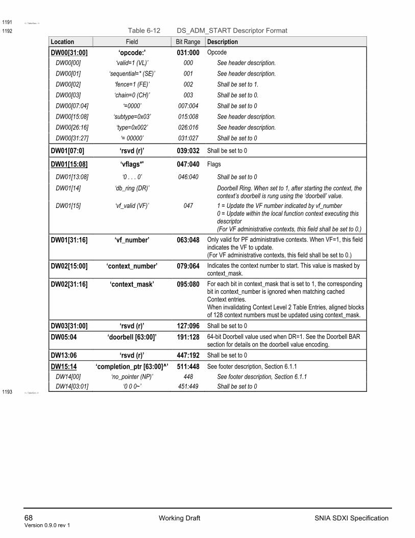
68 Working Draft SNIA SDXI Specification Version 0.9.0 rev 1
<!-- Table=Desc --!> 1191 Table 6-12 DS_ADM_START Descriptor Format 1192
Location Field Bit Range Description DW00[31:00] ‘opcode:' 031:000 Opcode
DW00[00] ‘valid=1 (VL)’ 000 See header description. DW00[01] ‘sequential=* (SE)’ 001 See header description. DW00[02] ‘fence=1 (FE)’ 002 Shall be set to 1. DW00[03] ‘chain=0 (CH)’ 003 Shall be set to 0. DW00[07:04] ‘=0000’ 007:004 Shall be set to 0 DW00[15:08] ‘subtype=0x03’ 015:008 See header description. DW00[26:16] ‘type=0x002’ 026:016 See header description. DW00[31:27] ‘= 00000’ 031:027 Shall be set to 0
DW01[07:0] ‘rsvd (r)’ 039:032 Shall be set to 0
DW01[15:08] ‘vflags*' 047:040 Flags
DW01[13:08] ‘0 . . . 0’ 046:040 Shall be set to 0 DW01[14] ‘db_ring (DR)’ Doorbell Ring. When set to 1, after starting the context, the
context’s doorbell is rung using the ‘doorbell’ value. DW01[15] ‘vf_valid (VF)’ 047 1 = Update the VF number indicated by vf_number
0 = Update within the local function context executing this descriptor (For VF administrative contexts, this field shall be set to 0.)
DW01[31:16] ‘vf_number’ 063:048 Only valid for PF administrative contexts. When VF=1, this field indicates the VF to update. (For VF administrative contexts, this field shall be set to 0.)
DW02[15:00] ‘context_number’ 079:064 Indicates the context number to start. This value is masked by context_mask.
DW02[31:16] ‘context_mask’ 095:080 For each bit in context_mask that is set to 1, the corresponding bit in context_number is ignored when matching cached Context entries. When invalidating Context Level 2 Table Entries, aligned blocks of 128 context numbers must be updated using context_mask.
DW03[31:00] ‘rsvd (r)’ 127:096 Shall be set to 0 DW05:04 ‘doorbell [63:00]’ 191:128 64-bit Doorbell value used when DR=1. See the Doorbell BAR
section for details on the doorbell value encoding. DW13:06 ‘rsvd (r)’ 447:192 Shall be set to 0 DW15:14 ‘completion_ptr [63:00]^’ 511:448 See footer description, Section 6.1.1
DW14[00] ‘no_pointer (NP)’ 448 See footer description, Section 6.1.1 DW14[03:01] ‘0 0 0~’ 451:449 Shall be set to 0
<!-- Table=End --!> 1193

SNIA SDXI Specification Working Draft 69 Version 0.9.0 rev 1
AdminGrp DS_ADM_STOP Operation 1194
The AdminGrp’s Stop operation stops a target context from processing new descriptors and changes the 1195 target context’s state to a relevant stopped state. The target context shall be stopped at a descriptor 1196 boundary. See 4.2 SDXI Context State for more details. 1197
The AdminGrp’s Stop operation shall complete in a timely manner so that further administrative operations 1198 may be executed. The operation is not required to wait for the target context to stop prior to completing. 1199 Software shall check the target context’s ContextStatus to determine whether the context has stopped. 1200
If a hard stop is specified, the SDXI function may abort outstanding operations rather than wait for them to 1201 complete normally to speed up the stop process. This may result in errors being reported in the error log. 1202
Figure 6-13 DS_ADM_STOP Descriptor Format 1203
1204
1205
31 30 29 28 27 26 25 24 23 22 21 20 19 18 17 16 15 14 13 12 11 10 9 8 7 6 5 4 3 2 1 0
DWORD00 CH FE SE VL
0 1 * 1
DWORD01 VF 0 HS
DWORD02DWORD03DWORD04DWORD05DWORD06DWORD07DWORD08DWORD09DWORD10DWORD11DWORD12DWORD13DWORD14 NP
DWORD15
rsvd (r)
0 0 0 completion_ptr [63:00]
rsvd (r)0 . . . 0 vf_number context_number context_mask
0000 0x04 0x002 00000< - - vflags - - >
< - - opcode - - > subtype type

70 Working Draft SNIA SDXI Specification Version 0.9.0 rev 1
<!-- Table=Desc --!> 1206 Table 6-13 DS_ADM_STOP Descriptor Format 1207
Location Field Bit Range Description DW00[31:00] ‘opcode:' 031:000 Opcode
DW00[00] ‘valid=1 (VL)’ 000 See header description. DW00[01] ‘sequential=* (SE)’ 001 See header description. DW00[02] ‘fence=1 (FE)’ 002 Shall be set to 1. DW00[03] ‘chain=0 (CH)’ 003 Shall be set to 0. DW00[07:04] ‘=0000’ 007:004 Shall be set to 0 DW00[15:08] ‘subtype=0x04’ 015:008 See header description. DW00[26:16] ‘type=0x002’ 026:016 See header description. DW00[31:27] ‘=00000’ 031:027 Shall be set to 0
DW01[07:0] ‘rsvd (r)’ 039:032 Shall be set to 0
DW01[15:08] ‘vflags*' 047:040 Flags
DW01[12:08] ‘0 . . . 0’ 044:040 Shall be set to 0 DW01[13] ‘hard_stop (HS)’ 045 Hard Stop. When HS=1, outstanding operations in the
affected context may be aborted prior to stopping the context. When HS=0, outstanding operations in the affected context shall complete normally prior to stopping the context.
DW01[14] ‘0’ 046 Shall be set to 0. DW01[15] ‘vf_valid (VF)’ 047 1 = Update the VF number indicated by vf_number
0 = Update within the local function context executing this descriptor (For VF administrative contexts, this field shall be set to 0.)
DW01[31:16] ‘vf_number’ 063:048 Only valid for PF administrative contexts. When VF=1, this field indicates the VF to update. (For VF administrative contexts, this field shall be set to 0.)
DW02[15:00] ‘context_number’ 079:064 Indicates the context number tostop. This value is masked by context_mask.
DW02[31:16] ‘context_mask’ 095:080 For each bit in context_mask that is set to 1, the corresponding bit in context_number is ignored when matching cached Context entries. When invalidating Context Level 2 Table Entries, aligned blocks of 128 context numbers must be updated using context_mask.
DW13:03 ‘rsvd (r)’ 447:096 Shall be set to 0 DW15:14 ‘completion_ptr [63:00]^’ 511:448 See footer description, Section 6.1.1
DW14[00] ‘no_pointer (NP)’ 448 See footer description, Section 6.1.1 DW14[03:01] ‘0 0 0~’ 451:449 Shall be set to 0
<!-- Table=End --!> 1208
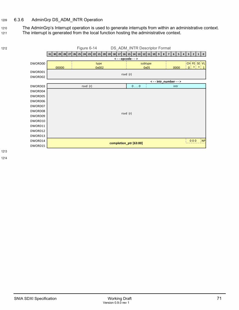
SNIA SDXI Specification Working Draft 71 Version 0.9.0 rev 1
AdminGrp DS_ADM_INTR Operation 1209
The AdminGrp’s Interrupt operation is used to generate interrupts from within an administrative context. 1210 The interrupt is generated from the local function hosting the administrative context. 1211
Figure 6-14 DS_ADM_INTR Descriptor Format 1212
1213
1214
31 30 29 28 27 26 25 24 23 22 21 20 19 18 17 16 15 14 13 12 11 10 9 8 7 6 5 4 3 2 1 0
DWORD00 CH FE SE VL
0 * * 1DWORD01DWORD02
DWORD03DWORD04DWORD05DWORD06DWORD07DWORD08DWORD09DWORD10DWORD11DWORD12DWORD13DWORD14 NP
DWORD150 0 0
completion_ptr [63:00]
< - - intr_number - - > intr 0 . . . 0 rsvd (r)
rsvd (r)
0000 0x05 0x002 00000
rsvd (r)
< - - opcode - - > subtype type

72 Working Draft SNIA SDXI Specification Version 0.9.0 rev 1
<!-- Table=Desc --!> 1215 Table 6-14 DS_ADM_INTR Descriptor Format 1216
Location Field Bit Range Description DW00[31:00] ‘opcode:' 031:000 Opcode
DW00[00] ‘valid=1 (VL)’ 000 See header description. DW00[01] ‘sequential=* (SE)’ 001 See header description. DW00[02] ‘fence=* (FE)’ 002 See header description. DW00[03] ‘chain=0 (CH)’ 003 Shall be set to 0. DW00[07:04] ‘=0000’ 007:004 Shall be set to 0 DW00[15:08] ‘subtype=0x05’ 015:008 See header description. DW00[26:16] ‘type=0x002’ 026:016 See header description. DW00[31:27] ‘= 00000’ 031:027 Shall be set to 0
DW02:01 ‘rsvd (r)’ 095:032 Shall be set to 0
DW03[15:00] ‘intr_number*’ 111:096 Interrupt
DW03[11:00] ‘intr’ 107:096 Specifies the MSI-X entry used to generate the interrupt.
DW03[15:12] ‘0 . . . 0’ 111:108 Shall be set to 0
DW03[31:16] ‘rsvd (r)’ 127:112 Shall be set to 0
DW13:04 ‘rsvd (r)’ 447:128 Shall be set to 0
DW15:14 ‘completion_ptr [63:00]^’ 511:448 See footer description, Section 6.1.1 DW14[00] ‘no_pointer (NP)’ 448 See footer description, Section 6.1.1 DW14[03:01] ‘0 0 0~’ 451:449 Shall be set to 0
<!-- Table=End --!> 1217

SNIA SDXI Specification Working Draft 73 Version 0.9.0 rev 1
AdminGrp DS_ADM_SYNC Operation 1218
The AdminGrp’s Sync operation acts as a synchronization barrier relative to prior AdminGrp’s Update 1219 operations that target the selected function, contexts, and AKeys. 1220
A successful completion of the Sync operation indicates the successful completion of all prior AdminGrp 1221 Update operations to the selected data structures and that all outstanding requests using prior non-1222 coherently cached copies of those data structures have completed. 1223
An error associated with Sync may indicate an error associated with a prior AdminGrp Update operation. 1224
Figure 6-15 DS_ADM_SYNC Descriptor Format 1225
1226
1227
31 30 29 28 27 26 25 24 23 22 21 20 19 18 17 16 15 14 13 12 11 10 9 8 7 6 5 4 3 2 1 0
DWORD00 CH FE SE VL
0 1 * 1
DWORD01 VF
DWORD02DWORD03DWORD04DWORD05DWORD06DWORD07DWORD08DWORD09DWORD10DWORD11DWORD12DWORD13DWORD14 NP
DWORD15
akey akey_mask
rsvd (r)
0 0 0 completion_ptr [63:00]
rsvd (r)0 . . . 0 vf_number context_number context_mask
0000 0x06 0x002 00000< - - vflags - - >
< - - opcode - - > subtype type

74 Working Draft SNIA SDXI Specification Version 0.9.0 rev 1
<!-- Table=Desc --!> 1228 Table 6-15 DS_ADM_SYNC Descriptor Format 1229
Location Field Bit Range Description DW00[31:00] ‘opcode:' 031:000 Opcode
DW00[00] ‘valid=1 (VL)’ 000 See header description. DW00[01] ‘sequential=* (SE)’ 001 See header description. DW00[02] ‘fence=1 (FE)’ 002 Shall be set to 1. DW00[03] ‘chain=0 (CH)’ 003 Shall be set to 0. DW00[07:04] ‘=0000’ 007:004 Shall be set to 0 DW00[15:08] ‘subtype=0x06’ 015:008 See header description. DW00[26:16] ‘type=0x002’ 026:016 See header description. DW00[31:27] ‘= 00000’ 031:027 Shall be set to 0
DW01[07:0] ‘rsvd (r)’ 039:032 Shall be set to 0
DW01[15:08] ‘vflags*' 047:040 Flags
DW01[14:08] ‘0 . . . 0’ 046:040 Shall be set to 0 DW01[15] ‘vf_valid (VF)’ 047 When VF=1, sync the VF number indicated by vf_number.
When VF=0, sync within the local function hosting the context executing this descriptor (For VF administrative contexts, this field shall be set to 0.)
DW01[31:16] ‘vf_number’ 063:048 Only valid for PF administrative contexts. When VF=1, this field indicates the VF to update. (For VF administrative contexts, this field shall be set to 0.)
DW02[15:00] ‘context_number’ 079:064 Indicates the context number to sync. This value is masked by ‘context_mask’.
DW02[31:16] ‘context_mask’ 095:080 For each bit in context_mask that is set to 1, the corresponding bit in context_number is ignored when matching context numbers.
DW03[15:00] ‘akey’ 111:096 Indicates the AKey value to sync. This value is masked by ‘akey_mask’.
DW03[31:16] ‘akey_mask’ 127:112 For each bit in akey_mask that is set to 1, the corresponding bit in ‘akey’ is ignored when matching AKey entry numbers
DW13:04 ‘rsvd (r)’ 447:128 Shall be set to 0 DW15:14 ‘completion_ptr [63:00]^’ 511:448 See footer description, Section 6.1.1
DW14[00] ‘no_pointer (NP)’ 448 See footer description, Section 6.1.1 DW14[03:01] ‘0 0 0~’ 451:449 Shall be set to 0
<!-- Table=End --!> 1230
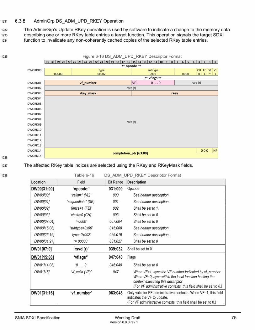
SNIA SDXI Specification Working Draft 75 Version 0.9.0 rev 1
AdminGrp DS_ADM_UPD_RKEY Operation 1231
The AdminGrp’s Update RKey operation is used by software to indicate a change to the memory data 1232 describing one or more RKey table entries a target function. This operation signals the target SDXI 1233 function to invalidate any non-coherently cached copies of the selected RKey table entries. 1234
Figure 6-16 DS_ADM_UPD_RKEY Descriptor Format 1235
1236
The affected RKey table indices are selected using the RKey and RKeyMask fields. 1237
Table 6-16 DS_ADM_UPD_RKEY Descriptor Format 1238
Location Field Bit Range Description DW00[31:00] ‘opcode:' 031:000 Opcode
DW00[00] ‘valid=1 (VL)’ 000 See header description. DW00[01] ‘sequential=* (SE)’ 001 See header description. DW00[02] ‘fence=1 (FE)’ 002 Shall be set to 1. DW00[03] ‘chain=0 (CH)’ 003 Shall be set to 0. DW00[07:04] ‘=0000’ 007:004 Shall be set to 0 DW00[15:08] ‘subtype=0x06’ 015:008 See header description. DW00[26:16] ‘type=0x002’ 026:016 See header description. DW00[31:27] ‘= 00000’ 031:027 Shall be set to 0
DW01[07:0] ‘rsvd (r)’ 039:032 Shall be set to 0
DW01[15:08] ‘vflags*' 047:040 Flags
DW01[14:08] ‘0 . . . 0’ 046:040 Shall be set to 0 DW01[15] ‘vf_valid (VF)’ 047 When VF=1, sync the VF number indicated by vf_number.
When VF=0, sync within the local function hosting the context executing this descriptor (For VF administrative contexts, this field shall be set to 0.)
DW01[31:16] ‘vf_number’ 063:048 Only valid for PF administrative contexts. When VF=1, this field indicates the VF to update. (For VF administrative contexts, this field shall be set to 0.)
31 30 29 28 27 26 25 24 23 22 21 20 19 18 17 16 15 14 13 12 11 10 9 8 7 6 5 4 3 2 1 0
DWORD00 CH FE SE VL0 1 * 1
DWORD01 VFDWORD02
DWORD03
DWORD04
DWORD05
DWORD06
DWORD07
DWORD08
DWORD09
DWORD10
DWORD11
DWORD12
DWORD13
DWORD14 NPDWORD15
⭠ opcode ⭢ type subtype
00000 0x002 0x07 0000⭠ vflags ⭢
vf_number 0 . . . 0 rsvd (r)
rsvd (r)
rkey_mask rkey
rsvd (r)
completion_ptr [63:00]0 0 0

76 Working Draft SNIA SDXI Specification Version 0.9.0 rev 1
Location Field Bit Range Description DW02[15:00] ‘context_number’ 079:064 Indicates the context number to sync. This value is masked by
‘context_mask’. DW02[31:16] ‘context_mask’ 095:080 For each bit in context_mask that is set to 1, the corresponding
bit in context_number is ignored when matching context numbers.
DW03[15:00] ‘akey’ 111:096 Indicates the AKey value to sync. This value is masked by ‘akey_mask’.
DW03[31:16] ‘akey_mask’ 127:112 For each bit in akey_mask that is set to 1, the corresponding bit in ‘akey’ is ignored when matching AKey entry numbers
DW13:04 ‘rsvd (r)’ 447:128 Shall be set to 0 DW15:14 ‘completion_ptr [63:00]^’ 511:448 See footer description, Section 6.1.1
DW14[00] ‘no_pointer (NP)’ 448 See footer description, Section 6.1.1 DW14[03:01] ‘0 0 0~’ 451:449 Shall be set to 0
1239
6.4 Atomic Operation Group (AtomicGrp) 1240
This operation group performs various atomic operations. All AtomicGrp operations use the same 1241 descriptor format. 1242
Figure 6-17 DS_ATM Descriptor Format 1243
1244
1245
31 30 29 28 27 26 25 24 23 22 21 20 19 18 17 16 15 14 13 12 11 10 9 8 7 6 5 4 3 2 1 0
DWORD00 CH FE SE VL
0 * * 1
DWORD01
DWORD02DWORD03DWORD04DWORD05DWORD06DWORD07DWORD08DWORD09DWORD10DWORD11DWORD12DWORD13DWORD14 NP
DWORD15
00 ret_data_ptr [63:00]
rsvd (r)
0 0 0 completion_ptr [63:00]
00 address0 [63:00] (Dst)
operand1 [63:00]
operand2 [63:00]
attr0 (Dst)0 . . . 0 rsvd (r)akey0 (Dst)rsvd (r)
0osz 000 rsvd (r)< - - attr - - >
0000 0x003 00000< - - size - - >
< - - opcode - - > subtype type

SNIA SDXI Specification Working Draft 77 Version 0.9.0 rev 1
<!-- Table=Desc --!> 1246 Table 6-17 DS_ATM Operation Descriptor Format 1247
Location Field Bit Range Description DW00[31:00] ‘opcode:' 031:000 Opcode
DW00[00] ‘valid =1 (VL)’ 000 See header description. DW00[01] ‘sequential = * (SE)’ 001 See header description. DW00[02] ‘fence = * (FE)’ 002 See header description. DW00[03] ‘chain=0 (CH)’ 003 Shall be set to 0. DW00[07:04] ‘= 0000’ 007:004 Shall be set to 0 DW00[15:08] ‘subtype’ 015:008 See header description. DW00[26:16] ‘type=0x003’ 026:016 See header description. DW00[31:27] ‘= 00000’ 031:027 Shall be set to 0
DW01[07:00] ‘size*' 039:032 Size DW01[01:00] ‘00’ 033:032 Shall be set to 0 DW01[04:02] ‘osz’ 036:034 The size of the operands in 4-byte increments minus 1:
000b = 4 bytes, 001b = 8 bytes. All other encodings reserved DW01[07:05] ‘000’ 039:037 Shall be set to 0
DW01[31:08] ‘rsvd (r)’ 063:040 Shall be set to 0
DW02[07:00] ‘attr*' 071:064 Attributes DW02[03:00] ‘attr0 (Dst)’ 067:064 Destination buffer attributes DW02[07:04] ‘0 . . . 0’ 071:068 Shall be set to 0 DW02[31:08] ‘rsvd (r)’ 095:072 Shall be set to 0 DW03[15:00] ‘akey0 (Dst)’ 111:096 Destination buffer AKey DW03[31:16] ‘rsvd (r)’ 127:112 Shall be set to 0
DW05:04 ‘address0 [63:00] (Dst)^’ 191:128 Destination buffer memory address to target for the atomic operation. The address shall be aligned to the operand size.
DW04[01:00] ‘00~’ 139:128 Shall be set to 0 DW07:06 ‘operand1 [63:00]’ 255:192 Operand 1 Data. If the operand size is set to 4 bytes, the lower 32 bits
of Operand1Data are utilized. DW09:08 ‘operand2 [63:00]’ 319:256 Operand 2 Data. If the operand size is set to 4 bytes, the lower 32 bits
of Operand1Data are utilized. DW11:10 ‘ret_data_ptr [63:00]^’ 383:320 Pointer to a naturally aligned operand size location in memory. The
original memory value at Address will be written back to this location. If this field is set to 0, no data is returned.
DW10[01:00] ‘00~’ 321:320 Shall be set to 0 DW13:12 ‘rsvd (r)’ 447:384 Shall be set to 0
DW15:14 ‘completion_ptr [63:00]^’ 511:448 See footer description, Section 6.1.1 DW14[00] ‘no_pointer (NP)’ 448 See footer description, Section 6.1.1 DW14[03:01] ‘0 0 0~’ 451:449 Shall be set to 0
<!-- Table=End --!> 1248

78 Working Draft SNIA SDXI Specification Version 0.9.0 rev 1
Table 6-18 Atomic Operations Sub-Type1,2,3,4 1249
Sub Type Operation 0x00 Reserved 0x01 Swap (OP_ATM_SWAP) *address0 = operand1; 0x02 Unsigned Add (OP_ATM_UADD) *address0 += operand1; 0x03 Unsigned Subtract (OP_ATM_USUB) *address0 -= operand1; 0x04 Reserved 0x05 AND (OP_ATM_AND) *address0 &= operand1; 0x06 OR (OP_ATM_OR) *address0 |= operand1; 0x07 XOR (OP_ATM_XOR) *address0 ^= operand1; 0x08 Signed Min (OP_ATM_SMIN)5 if (*address0 > operand1){ address0 = operand1; } 0x09 Signed Max (OP_ATM_SMAX)5 if (*address0 < operand1){ address0 = operand1; } 0x0A Unsigned Min (OP_ATM_UMIN)5 if (*address0 > operand1){ address0 = operand1; } 0x0B Unsigned Max (OP_ATM_UMAX)5 if (*address0 < operand1){ address0 = operand1; } 0x0C Unsigned Clamping Increment (OP_ATM_UCLAMPI) *address0 = (*address0 >= operand1) ? operand1 : *address + 1; 0x0D Unsigned Clamping Decrement (OP_ATM_UCLAMPD) *address0 = (*address0 == 0 || *address0 > operand1) ? operand1 : *address - 1; 0x0E Compare and Swap (OP_ATM_CMPSWAP)5 if (*address0 == operand1){ address0 = operand2; } All other encodings are Reserved
1. The sequence of reading and writing (or releasing) address0 by the SDXI function must be atomic 1250 with respect to operations of other agents on address0. 1251
2. ‘*nnn’ means the memory contents pointed to by nnn. 1252
3. All operations are performed at the specified operand size and all operands must be naturally 1253 aligned to that size. 1254
4. Before each operation above, the following pre-operation is always done: 1255 if (ret_data_ptr){ *ret_data_ptr = *address0; } 1256
5. Note: Provided that the atomicity requirements are met, an SDXI implementation is permitted to write 1257 back the unchanged content of address0 when the condition is false. 1258
1259

SNIA SDXI Specification Working Draft 79 Version 0.9.0 rev 1
6.5 IntrGrp Operation Group 1260
IntrGrp DS_INTERRUPT Operation 1261
The IntrGrp’s Interrupt operation is used to generate an interrupt. The interrupt number and address space 1262 are specified in the referenced AKey. 1263
Figure 6-18 DS_INTERRUPT Descriptor Format 1264
1265
31 30 29 28 27 26 25 24 23 22 21 20 19 18 17 16 15 14 13 12 11 10 9 8 7 6 5 4 3 2 1 0
DWORD00 CH FE SE VL
0 * * 1DWORD01DWORD02DWORD03DWORD04DWORD05DWORD06DWORD07DWORD08DWORD09DWORD10DWORD11DWORD12DWORD13DWORD14 NP
DWORD15
akey rsvd (r)
rsvd (r)
0 0 0 completion_ptr [63:00]
0000 0x00 0x004 00000
rsvd (r)
< - - opcode - - > subtype type

80 Working Draft SNIA SDXI Specification Version 0.9.0 rev 1
<!-- Table=Desc --!> 1266 Table 6-19 DS_INTERRUPT Descriptor Format 1267
Location Field Bit Range Description DW00[31:00] ‘opcode:' 031:000 Opcode
DW00[00] ‘valid =1 (VL)’ 000 See header description. DW00[01] ‘sequential = * (SE)’ 001 See header description. DW00[02] ‘fence = * (FE)’ 002 See header description. DW00[03] ‘chain=0 (CH)’ 003 Shall be set to 0. DW00[07:04] ‘= 0000’ 007:004 Shall be set to 0. DW00[15:08] ‘subtype=0x00’ 015:008 See header description. DW00[26:16] ‘type=0x004’ 026:016 See header description. DW00[31:27] ‘= 00000’ 031:027 Shall be set to 0
DW02:01 ‘rsvd (r)’ 095:032 Shall be set to 0
DW03[15:00] ‘akey’ 107:096 AKey used for this operation
DW03[31:16] ‘rsvd (r)’ 127:108 Shall be set to 0
DW13:04 ‘rsvd (r)’ 447:128 Shall be set to 0
DW15:14 ‘completion_ptr [63:00]^’ 511:448 See footer description, Section 6.1.1 DW14[00] ‘no_pointer (NP)’ 448 See footer description, Section 6.1.1 DW14[03:01] ‘0 0 0~’ 451:449 Shall be set to 0
<!-- Table=End --!> 1268

SNIA SDXI Specification Working Draft 81 Version 0.9.0 rev 1
6.6 Vendor Defined Operation Group 1269
The desired expansion model for new SDXI function operations is to create a new architectural operation 1270 group within this specification with architected operations. This prevents fragmentation of the architecture. 1271 But there may be rare circumstances where an SDXI function vendor has a need to create a non-1272 standard, vendor-specific operation. Such an operation shall use the format of the DS_VENDOR 1273 descriptor. Using a standard format allows leveraging of the standard software ecosystem for SDXI. 1274
Figure 6-19 DS_VENDOR Descriptor Format 1275
1276 <!-- Table=Desc --!> 1277
Table 6-20 DS_VENDOR Descriptor Format 1278
Location Field Bit Range Description DW00[31:00] ‘opcode:' 031:000 Opcode
DW00[00] ‘valid =1 (VL)’ 000 See header description. DW00[01] ‘sequential = * (SE)’ 001 See header description. DW00[02] ‘fence = * (FE)’ 002 See header description. DW00[03] ‘chain = * (CH)’ 003 See header description. DW00[07:04] ‘= 0000’ 007:004 Shall be set to 0 DW00[15:08] ‘subtype’ 015:008 Vendor-Defined. DW00[26:16] ‘type’ 026:016 Vendor-Defined but must be between 0x7F8 – 0x7FF. DW00[31:27] ‘= 00000’ 031:027 Shall be set to 0
DW01[15:00] ‘vendor_id’ 047:032 PCI vendor ID for the vendor that defined the descriptor encoding.
DW01[31:16] ‘vendor [015:000]’ 063:048 These bits are defined by the vendor based on the VendorID and SubType fields
DW13:02 ‘vendor [399:016]’ 447:064 These bits are defined by the vendor based on the VendorID and SubType fields
DW15:14 ‘completion_ptr [63:00]^’ 511:448 See footer description, Section 6.1.1 DW14[00] ‘no_pointer (NP)’ 448 See footer description, Section 6.1.1 DW14[03:01] ‘0 0 0~’ 451:449 Shall be set to 0
<!-- Table=End --!> 1279
31 30 29 28 27 26 25 24 23 22 21 20 19 18 17 16 15 14 13 12 11 10 9 8 7 6 5 4 3 2 1 0
DWORD00 CH FE SE VL
* * * 1DWORD01DWORD02DWORD03DWORD04DWORD05DWORD06DWORD07DWORD08DWORD09DWORD10DWORD11DWORD12DWORD13DWORD14 NP
DWORD15
vendor [399:016]
0 0 0 completion_ptr [63:00]
0000 00000vendor_id vendor [015:000]
< - - opcode - - > subtype type

82 Working Draft SNIA SDXI Specification Version 0.9.0 rev 1
7 Function Initialization and Context Management 1280
7.1 Function Initialization 1281
In order to initialize an SDXI function, the following basic steps shall be taken: 1282
1. Read the SDXI MMIO Capability registers to discover the supported SDXI features 1283
2. Write the appropriate SDXI MMIO Capability registers to enable supported SDXI features 1284
3. Read the SDXI MMIO Capabilities register to discover the feature set exposed to driver software 1285
4. Initialize the Error Log. Refer to the Error Logging section for more details 1286
5. Allocate an aligned 4KB region of memory for the Context Level 2 Table 1287
6. Initialize all Context Level 2 Table entries to 0 1288
7. Program the Context Table Base register to point to the Context Level 2 Table location in memory. 1289
• If guest virtual addressing is required, set Control0.FunctionPASID and 1290 Control0.FunctionPASIDValid to appropriate values 1291
8. If present, initialize the mailbox registers 1292
9. Set MmioControl0.Enable to 11b 1293
After basic initialization, Context Level 1 Table structures may be added. Subsequently, Contexts may be 1294 created to host descriptor rings. It is recommended that an Administrative Context be the first context 1295 created within an SDXI function. 1296
Software may also need to configure additional PCIe standards-based features such as MSI/MSI-X, ATS, 1297 PRI, or TPH based on the desired use cases. 1298
7.2 Context Management 1299
Caching of Memory Data Structures 1300
The function may cache various memory data structures using private caches that are not coherent with 1301 respect to processor caches. Data in both the valid and invalid states may be cached in this manner. 1302 Software must use the appropriate AdminGrp.Update and AdminGrp.Sync commands to notify the 1303 function when memory data structures have changed. 1304
The function may cache any of the following data structures: 1305
• Context level 1 table entry 1306
• Context level 2 table entry 1307
• Context control entry 1308
• AKey table entry 1309
• Valid descriptors located between the read and write pointer of the associated descriptor ring 1310
• Context Status Entry of a running context 1311
1312

SNIA SDXI Specification Working Draft 83 Version 0.9.0 rev 1
Modify or Delete a Context Level 2 Table Entry 1313
In order to modify or delete an existing Context Level 2 Table entry, the following steps may be followed: 1314
1. Atomically modify the Context Level 2 Table Entry data in memory 1315
2. Issue an Update Context operation targeting the Context Number to an appropriate Administrative 1316 Context with the following settings 1317
• L2=1 1318 • L1=1 1319 • CT=1 1320 • context_mask=0x007F 1321 • context_number={Context Level 2 Table Entry offset, 0000000b} 1322
3. Issue a Sync operation into the same descriptor ring as the prior Update operation 1323
4. Wait for the completion signal of the Sync operation 1324
Add Context Level 1 Table 1325
In order to add a Context Level 1 Table, the following steps may be followed: 1326
1. Identify a free Context Level 2 Table Entry 1327
2. Allocate an aligned 4KB region of memory 1328
3. Initialize the memory region to zero 1329
4. Program the Context Level 2 Table Entry to point to the new memory region 1330
5. Set the Context Level 2 Table entry Valid bit to 1 1331
6. Issue an Update Context operation targeting this Context Number into the descriptor ring of an 1332 Administrative Context with the following settings 1333
• L2=1 1334 • L1=1 1335 • CT=1 1336 • context_mask=0x007F 1337 • context_number={Context Level 2 Table Entry offset, 0000000b} 1338
7. Issue a Sync operation into the same descriptor ring as the prior Update operation 1339
8. Wait for the Completion signal of the Sync operation 1340
Modify or Delete a Context Level 1 Table Entry 1341
In order to modify or delete an existing Context Level 1 Table Entry, the following steps may be followed if 1342 the memory data can be atomically modified: 1343
1. Atomically modify the relevant portion of the Context Level 1 Table Entry data in memory 1344
2. Issue an Update Context operation targeting this Context Number into the descriptor ring of an 1345 Administrative Context with the following settings 1346
• L2=0 1347 • L1=1 1348 • CT=1 1349 • context_mask=0x0000 1350 • context_number={Context Level 2 Table Entry offset, Context Level 1 Table Entry offset} 1351
3. Issue a Sync operation into the same descriptor ring as the prior Update operation 1352
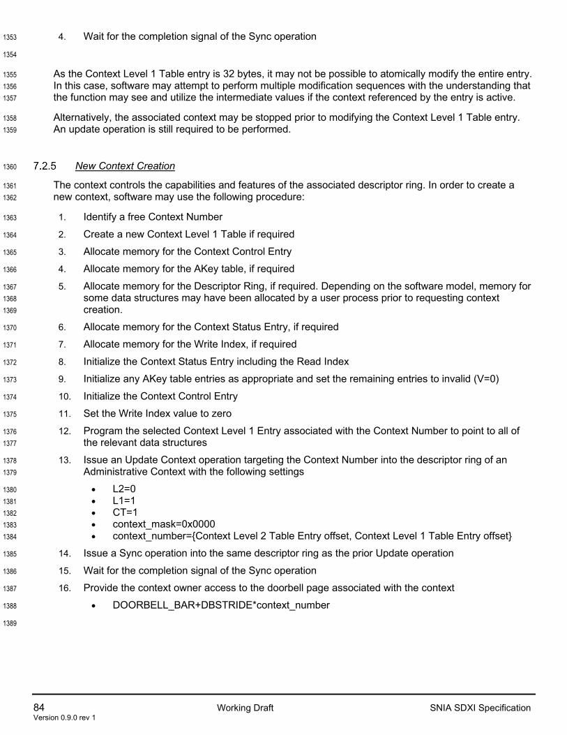
84 Working Draft SNIA SDXI Specification Version 0.9.0 rev 1
4. Wait for the completion signal of the Sync operation 1353
1354
As the Context Level 1 Table entry is 32 bytes, it may not be possible to atomically modify the entire entry. 1355 In this case, software may attempt to perform multiple modification sequences with the understanding that 1356 the function may see and utilize the intermediate values if the context referenced by the entry is active. 1357
Alternatively, the associated context may be stopped prior to modifying the Context Level 1 Table entry. 1358 An update operation is still required to be performed. 1359
New Context Creation 1360
The context controls the capabilities and features of the associated descriptor ring. In order to create a 1361 new context, software may use the following procedure: 1362
1. Identify a free Context Number 1363
2. Create a new Context Level 1 Table if required 1364
3. Allocate memory for the Context Control Entry 1365
4. Allocate memory for the AKey table, if required 1366
5. Allocate memory for the Descriptor Ring, if required. Depending on the software model, memory for 1367 some data structures may have been allocated by a user process prior to requesting context 1368 creation. 1369
6. Allocate memory for the Context Status Entry, if required 1370
7. Allocate memory for the Write Index, if required 1371
8. Initialize the Context Status Entry including the Read Index 1372
9. Initialize any AKey table entries as appropriate and set the remaining entries to invalid (V=0) 1373
10. Initialize the Context Control Entry 1374
11. Set the Write Index value to zero 1375
12. Program the selected Context Level 1 Entry associated with the Context Number to point to all of 1376 the relevant data structures 1377
13. Issue an Update Context operation targeting the Context Number into the descriptor ring of an 1378 Administrative Context with the following settings 1379
• L2=0 1380 • L1=1 1381 • CT=1 1382 • context_mask=0x0000 1383 • context_number={Context Level 2 Table Entry offset, Context Level 1 Table Entry offset} 1384
14. Issue a Sync operation into the same descriptor ring as the prior Update operation 1385
15. Wait for the completion signal of the Sync operation 1386
16. Provide the context owner access to the doorbell page associated with the context 1387
• DOORBELL_BAR+DBSTRIDE*context_number 1388
1389

SNIA SDXI Specification Working Draft 85 Version 0.9.0 rev 1
Modify a Context Control Entry 1390
Software may modify a Context Control Entry using the following procedure. 1391
1. Modify the Context Control Entry in memory 1392
2. Issue an Update Context operation targeting this Context Number into the descriptor ring of an 1393 Administrative Context with the following settings 1394
• L2=0 1395 • L1=0 1396 • CT=1 1397 • context_mask=0x0000 1398 • context_number={Context Level 2 Table Entry offset, Context Level 1 Table Entry offset} 1399
3. Issue a Sync operation into the same descriptor ring as the prior Update operation 1400
4. Wait for the completion signal of the Sync operation 1401
1402
It may be difficult to atomically modify the context control entry as it is 64 bytes in size. The function may 1403 see either the old or new value of the context control entry from the time it is modified in memory until the 1404 point at which software sees the completion signal get updated for the Sync operation. There are several 1405 approaches that may be considered: 1406
Software may be able to determine a safe sequence of modifications depending on the fields that need to 1407 be modified. Care shall be taken as intermediate values may be processed by the function if the context is 1408 running. 1409
Software may stop the context, modify the context entry and then restart the context. 1410
Another option is to construct a new version of the context entry in an alternate location in memory and 1411 then modify the context level 1 table entry to point to the new location. Software shall issue an Update 1412 operation for the context level 1 table entry followed by a Sync operation and wait for the Sync completion. 1413 If the context is running, the transition to the new context control entry information is asynchronous relative 1414 to the processing of the context’s descriptors and is not guaranteed to occur on a descriptor boundary. 1415
Modify or Delete an AKey Table Entry 1416
Software may modify or delete an AKey table entry by updating the entry in memory and then enqueueing 1417 either an Update Function or Update AKey Table Entry descriptor into the ring of an associated 1418 Administrative Context. 1419
1. Modify the AKey table entry in memory 1420
2. Issue an Update AKey Table Entry operation into the descriptor ring of an Administrative Context 1421 with the following settings 1422
• context_mask=0x0000 1423 • context_number={Context Level 2 Table Entry offset, Context Level 1 Table Entry offset} 1424 • AKeyMask=0x0000 1425 • AKeyNumber= AKey table entry offset 1426
3. Issue a Sync operation into the same descriptor ring as the prior Update operation 1427
4. Wait for the completion of the Sync operation 1428
1429
If the entry is modified in a non-atomic manner, it is possible for an implementation to see and use an 1430 intermediate value. The function may use either the old or new value of the AKey Table Entry from the 1431

86 Working Draft SNIA SDXI Specification Version 0.9.0 rev 1
time it is modified in memory until the point at which software sees the completion signal update for the 1432 Sync operation. Software must take proper care to ensure that these possibilities are accommodated. For 1433 example, software may ensure that no descriptors will use the target AKey Table Entry during the 1434 modification process, or software may ensure that all intermediate states are safe. 1435
Start a Context 1436
In order to execute descriptors, a context must meet all of the following conditions: 1437
1. The function must be in the Active state (MmioStatus0.GlobalState==Active) 1438
2. Context Level 2 Table Entry must be readable by the function and valid (CL2TE.V=1) 1439
3. Context Level 1 Table Entry must be readable by the function, valid (CL1TE.V=1) and active 1440 (CL1TE.A=1) 1441
4. Context Control Entry must be readable by the function and valid (CCE.V=1) 1442
5. Context Status Entry must indicate ContextState==Running 1443
6. Write Index memory location must be readable 1444
7. Write Index memory value must be greater than the Read Index value 1445
8. Doorbell write targeting the context must be received with a value greater than Read Index 1446
In order to set ContextState==Running, software may issue a Start Context descriptor in an appropriate 1447 Administrative Context. Software may also manually modify the Context State Entry memory to indicate 1448 ContextState==Running. This is necessary when starting the first context. 1449
A doorbell write may be generated by performing an MMIO write to the appropriate address within the 1450 doorbell BAR. When using a Start Context descriptor, a doorbell access may also be generated from 1451 within the descriptor by setting the DR flag and supplying an appropriate DoorbellValue. 1452
Refer to 4.2 SDXI Context State for more details. 1453
Restore and Resume a Context 1454
Software may load a previously saved context. This may be done in case time sharing of a context is 1455 required, or as part of live migration. There is no requirement to restore a context to the same context 1456 number that was previously used. Context numbers are only referenced by admin operations and error 1457 logs. They are not intended to be exposed to any user processes that may be controlling a context 1458 descriptor ring. 1459
To restore a context, the following procedure may be used: 1460
1. Locate a free context number 1461
2. Add an additional Context Level 1 Table if necessary 1462
3. Load all of the context data structures into memory 1463
4. Modify AKey table entry contents as necessary 1464
5. Program the Context Level 1 Entry associated with the selected context number to point to the data 1465 structures in memory 1466
6. Enqueue a Context Start descriptor into the ring of an appropriate Administrative Context. Set DR=1 1467 and DoorbellValue = all-F if the context was stopped with pending descriptors. 1468
7. Map the appropriate doorbell page associated with the new context number to the context owner 1469
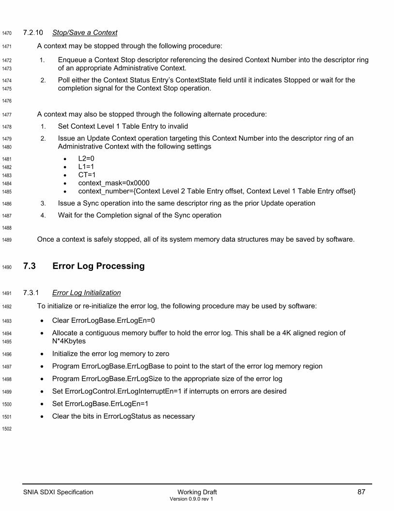
SNIA SDXI Specification Working Draft 87 Version 0.9.0 rev 1
Stop/Save a Context 1470
A context may be stopped through the following procedure: 1471
1. Enqueue a Context Stop descriptor referencing the desired Context Number into the descriptor ring 1472 of an appropriate Administrative Context. 1473
2. Poll either the Context Status Entry’s ContextState field until it indicates Stopped or wait for the 1474 completion signal for the Context Stop operation. 1475
1476
A context may also be stopped through the following alternate procedure: 1477
1. Set Context Level 1 Table Entry to invalid 1478
2. Issue an Update Context operation targeting this Context Number into the descriptor ring of an 1479 Administrative Context with the following settings 1480
• L2=0 1481 • L1=1 1482 • CT=1 1483 • context_mask=0x0000 1484 • context_number={Context Level 2 Table Entry offset, Context Level 1 Table Entry offset} 1485
3. Issue a Sync operation into the same descriptor ring as the prior Update operation 1486
4. Wait for the Completion signal of the Sync operation 1487
1488
Once a context is safely stopped, all of its system memory data structures may be saved by software. 1489
7.3 Error Log Processing 1490
Error Log Initialization 1491
To initialize or re-initialize the error log, the following procedure may be used by software: 1492
• Clear ErrorLogBase.ErrLogEn=0 1493
• Allocate a contiguous memory buffer to hold the error log. This shall be a 4K aligned region of 1494 N*4Kbytes 1495
• Initialize the error log memory to zero 1496
• Program ErrorLogBase.ErrLogBase to point to the start of the error log memory region 1497
• Program ErrorLogBase.ErrLogSize to the appropriate size of the error log 1498
• Set ErrorLogControl.ErrLogInterruptEn=1 if interrupts on errors are desired 1499
• Set ErrorLogBase.ErrLogEn=1 1500
• Clear the bits in ErrorLogStatus as necessary 1501
1502

88 Working Draft SNIA SDXI Specification Version 0.9.0 rev 1
Error Log Overflow Recovery 1503
On an error log overflow event, software may use the following sequence free up space in the error log 1504 and resume error loging: 1505
• Process one or more error log entries starting from ErrLogRptr 1506
• Advance ErrLogRptr 1507
• Clear ErrorLogStatus.ErrLogOverflow and ErrorLogStatus.ErrLogStatus 1508
7.4 Reset 1509
When an SDXI function is reset, it is possible that there are outstanding DMA requests from the function to 1510 both local and remote address spaces. The resetting function may receive DMA from other SDXI functions 1511 targeting the function’s local address spaces. Those remote functions may continue to issue new DMA 1512 requests attempting to access the resetting function’s local address spaces during reset. The function 1513 must clean up all outstanding DMAs during the reset process. 1514
After reset has completed, the function does not generate DMA requests until it is reinitialized by software. 1515 All remote function DMA targeting local address spaces is aborted. 1516
It is privileged software’s responsibility to notify the remote software contexts that the target function is 1517 being reset. It shall also ensure either orderly or unorderly removal of all associated connections prior to 1518 re-enabling the VF that was reset. 1519
7.5 Mailbox Interface 1520
The PF/VF mailbox interface allows for low-bandwidth two-way communication between privileged 1521 software and each of the software contexts. This may be used directly during runtime to pass control 1522 messages between privileged software and the VMs. It may also be used to bootstrap higher bandwidth 1523 forms of communication such as shared memory buffers, or even memory ring-buffers and interrupts that 1524 are written or generated by SDXI contexts. 1525
It is recommended that under virtualization, the Hypervisor take ownership of all SDXI PFs in order to 1526 facilitate communication between VFs under the same PF, and between SDXI VFs belonging to different 1527 PFs within the same SDXI function group. 1528
7.6 Descriptor Driven Interrupts 1529
Interrupts generated by descriptors do not set any sort of internal MMIO status as may be present in 1530 traditional devices. Any interrupt status is expected to be maintained in memory. 1531
For these interrupts, the function does not explicitly know when interrupt service is complete. These 1532 interrupts must be edge triggered as the function does not know when to de-assert a level-sensitive 1533 interrupt. Additionally, if MSI or MSI-X Pending bits are implemented, the Pending state will not be change 1534 from Set to Clear while the associated vector is masked. 1535

SNIA SDXI Specification Working Draft 89 Version 0.9.0 rev 1
8 SDXI PCI-Express Device Architecture 1536
SDXI is based on the PCI-Express device and software architecture including the use of configuration and 1537 MMIO register spaces and standard PCI-Express capabilities including, but not limited to, PCI Power 1538 Management, MSI/MSI-X interrupts and SR-IOV. 1539
SDXI may be implemented using a range of function types such as PCIe EP or RCiEP. It may be 1540 implemented as either a Physical Function or Virtual Function. 1541
Each SDXI function shall support standard PCI-Express defined reset mechanisms such as fundamental 1542 reset and hot-reset. 1543
If SR-IOV is supported, PFs and VFs shall support Function Level Reset (FLR). 1544
8.1 SDXI Function Configuration Space Registers 1545
Figure 8-1 PCI Config Space 1546
1547
1548
Class Code 1549
SDXI utilizes the following class code: 1550
Base Class = 0x12, Sub Class = 0x01, Programming Interface = 0x0 – SNIA Smart Data Accelerator 1551 Interface (SDXI) controllerSDXI functions are expected to be identified through the SDXI class code. 1552
31 30 29 28 27 26 25 24 23 22 21 20 19 18 17 16 15 14 13 12 11 10 9 8 7 6 5 4 3 2 1 0
+000h
+004h
+008h
MF +00Ch
+010h
+014h
+018h
+01Ch
+020h
+024h
+028h
+02Ch
+030h
+034h
+038h
+03Ch
SE PE BM MS I/O0x0
SC0x0
WI0x0
PS0x0
SWC0x0rsvdPIRIS
0x0CAP0x1
660x0MDPSTARTARMA rsvdrsvd
⭠Command ⭢
Capabilities Pointer
Bar 0/1 Prefetchable Memory for MMIO Registers
Bar 2/3 Prefetchable Memory for Doorbells
Bar 4 - Reserved 0x0Bar 5 - Reserved 0x0
Cardbus CIS Pointer - 0x0Subsystem ID Subsystem Vendor ID
Expansion ROM Base Address - 0x0
SSEDPE DEVSEL0x0
ID0x0
FBE0x0
FBC0x0
Interrupt Pin - 0x0 Interrupt Line
Vendor IDDevice ID
Revision ID
Cache Line SizeLatency Timer - 0x0BIST
Base Class - 0x12 Sub-Class - 0x1 Prog I/F - 0x0
Header Layout - 0x0
⭠Status ⭢
⭠Class Code ⭢
Max_Lat - 0x0 Min_Gnt - 0x0
Reserved

90 Working Draft SNIA SDXI Specification Version 0.9.0 rev 1
BAR Configuration 1553
Table 8-1 BAR Configuration 1554
PCI Bar Index Width Size Type Description
Bar 0/1 64 bit 512KiB to 4MiB for PF. 512KiB for VF
Prefetchable, Memory
MMIO Registers
Bar 2/3 64 bit Variable Prefetchable, Memory
Doorbell BAR
Bar 4 Reserved
Bar 5 Reserved
1555
If MSI-X is supported, the MSI-X table and PBA Offset table may be placed within any of the BARs 1556 including the reserved ones depending on hardware implementation. A block of MMIO space within 1557 BAR0/1 is reserved for use by MSI-X tables. Implementations are not required to use this reserved MMIO 1558 region. 1559
The MMIO register BAR is marked as prefetchable to allow software to allocate the region within 64-bit 1560 MMIO space in order to avoid exhaustion of 32-bit MMIO space when implementing SR-IOV with many 1561 virtual functions. Please refer to the implementation note in the PCI-Express Base Specification which 1562 provides additional guidance on the use of the prefetchable attribute. 1563
1564

SNIA SDXI Specification Working Draft 91 Version 0.9.0 rev 1
Required Capabilities and Extended Capabilities 1565
SDXI functions are required to support the following capabilities: 1566
• PCI Power Management 1567
• MSI and/or MSI-X 1568
Additional PCIe capabilities such as Advanced Error Reporting, Transaction Processing Hints, and Single 1569 Root I/O Virtualization are optional. See section 7.4 for reset requirements. 1570

92 Working Draft SNIA SDXI Specification Version 0.9.0 rev 1
9 MMIO Control Registers 1571
MMIO registers are grouped by function with each function separated within a separate 64Kbyte region to 1572 facilitate CPU MMU-based protection and emulation across a range of possible processor architectures. 1573 PFs may implement an MMIO region of between 512KB and 4MB depending on the amount of MMIO 1574 space required to hold mailboxes for the number of supported VFs. VFs each consume 512KB of MMIO 1575 space 1576
1577
The requirements to access an SDXI function's MMIO register are described here. Software should not 1578 depend on the results of any unsupported access (as described in this section) to these MMIO registers. A 1579 misaligned access that straddles MMIO registers is not supported and results in undefined operation of the 1580 SDXI function. A write to an MMIO register must be ordered with respect to other accesses to the same 1581 register; software must use processor-specific means to ensure that the required memory ordering is 1582 enforced. 1583
The SDXI function's MMIO registers are located in PCIe prefetchable memory space. While it is expected 1584 that most platforms will not merge separate writes to a PCIe endpoint, software may be required on some 1585 platforms to work around this when writing SDXI function MMIO registers. Please consult platform-specific 1586 references and the 5.0 PCIe Base Specification -- Implementation Note: "Additional Guidance on the 1587 Prefetchable Bit in Memory Space BARS". 1588
The SDXI function's MMIO register space is segmented logically into two regions for the purposes of 1589 discussing the access model: the Doorbell MMIO registers, and the remaining MMIO registers. 1590
For the Doorbell MMIO registers, only a naturally-aligned 64-bit write is supported. Any other write access 1591 is ignored by the SDXI function. A read access of a Doorbell MMIO register is not supported; the SDXI 1592 function must return a result but the result is architecturally undefined. 1593
For the remaining MMIO registers, the SDXI function supports all naturally-aligned accesses up to 64-bits 1594 as atomic with one exception: if an implementation can not support 64-bit atomic accesses it will report 1595 MmioCapabilities1.Mmio64 as '0'. Misaligned reads and writes within an MMIO register are not supported; 1596 the SDXI function is allowed to return or write stale data as determined by the access type. Attempting to 1597 write reserved fields in an MMIO register with an illegal value results in an undefined value for the register. 1598
A "torn" read or write of an MMIO register can result when at least two agents - any of the SDXI function or 1599 one or more software threads -- are concurrently accessing the fields of the register in a non-atomic 1600 manner. The torn access can result in stale data being intermixed with more recent data in an 1601 unpredictable way. Software is solely responsible for avoiding torn reads and writes on accesses that 1602 straddle fields within an MMIO register. Software shall solely ensure synchronized access among multiple 1603 software threads; the method for which is beyond the scope of this specification. 1604
In an environment with synchronized software access, the following list describes methods a single 1605 software thread can use to avoid undefined operation and torn accesses with respect to the SDXI function 1606 itself; SDXI implementations shall ensure that these methods are supported. 1607
• If the register is not dynamically updated by the SDXI function, then any naturally-aligned read will 1608 avoid returning torn data. 1609
• When the SDXI function's MmioControl0.GlobalState is "Stopped", any naturally-aligned read or write 1610 will avoid torn data. 1611
• This is the only supported method for MmioContextTblBase (MMIO Offset: 0x1_0000) 1612
• If possible, use a supported naturally-aligned atomic read or write that maps solely to complete fields 1613 in the MMIO register. 1614

SNIA SDXI Specification Working Draft 93 Version 0.9.0 rev 1
If the MMIO register has an associated valid/enable bit (in some cases this is in another MMIO register), then disable or 1615 invalidate the register, read the enable/valid bit back to confirm it has changed value, make modifications, and then 1616
enable or validate the register.Table 9-1 MMIO Control Registers 1617
9.1 General Control and Status Registers 1618
Table 9-2 MmioControl0 (MMIO Offset :0x0_0000) 1619
Bits Field Type Reset Value Description
1:0 Enable RW 0x0 Controls the SDXI function state. See 4.1 SDXI Function State for more detail.
2 FunctionPASIDValid RW 0x0 Indicates whether the FunctionPASID field is used when accessing context level 2 or 1 table entries, Context Control Entries, AKey table entries, and error log entries. If FunctionPASIDValid=0, requests to the referenced data structures are accessed using non-PASID DMA requests.
3 Reserved R 0x0 4 FunctionErrIntEn RW 0x0 1=An interrupt is signaled when hardware transitions the
function to the Stopped-On-Error state as reported through MmioStatus0.GlobalState. When MSI or MSI-X is enabled, message 0 is signaled. 0=No interrupt is generated
7:5 Reserved R 0x0 27:8 FunctionPASID RW 0x0 Function PASID value. 31:28 Reserved R 0x0 39:32 GroupID RW 0x0 In a multi-function implementation of SDXI, all functions
connected within an SDXI function group reflect the same GroupID value written into any group member’s copy of this register. Software may identify all functions within a function group by writing a non-zero value into the GroupID field of one function and scanning for the same value in other SDXI functions. The GroupID register is only used to identify functions within the same SDXI function group. It is not referenced by other SDXI registers or data structures. See 2.2.3 SDXI Function Groups for more details.
64KB Region PF Usage VF Usage
0x00_0000 General Control and Status Registers
0x01_0000 Context Table Registers
0x02_0000 Error Logging Control and Status Registers
0x03_0000 Mailbox Control Registers
0x04_0000 Reserved for MSI-X
0x05_0000 Reserved
0x06_0000 to 0x25_FFFF Alternating 64K regions of Send and Receive Mailboxes
Send Mailbox at 0x6_0000. Receive Mailbox at 0x7_0000.
0x26_0000 to 0x3F_FFFF Reserved N/A

94 Working Draft SNIA SDXI Specification Version 0.9.0 rev 1
Bits Field Type Reset Value Description
63:40 Reserved R 0x0 1620
Table 9-3 MmioControl1 (MMIO Offset: 0x0_0008) 1621
Bits Field Type Reset Value Description
63:1 Reserved R 0x0
0 AllContextDB W 0x0 Writing this field to 1 is equivalent to generating a doorbell with a value of 0xFFFF_FFFF_FFFF_FFFF to all contexts within this function. This field always reads back as 0.
1622
Table 9-4 MmioControl2 (MMIO Offset: 0x0_0010) 1623
Bits Field Type Reset Value Description
3:0 MaxBufferCntl RW MaxBuffer This field controls the maximum data buffer size enabled for use by this function. The field is encoded the same as MmioCapabilities1.MaxBuffer and must not exceed it in value.
11:5 Reserved R 0x0
7:5 Reserved R 0x0
11:8 Reserved R 0x0
15:12 MaxAKTSizeCntl RW MaxAKTSize This field controls the maximum size of any AKey table useable by any context within this function. The field is encoded the same asMmioCapabilities1.MaxAKTSize and must not exceed it in value.
31:16 NContextsCntl RW NContexts This field controls the maximum number of contexts enabled for use by this function. The field is encoded the sameMmioCapabilities1.NContexts and must not exceed it in value.
63:32 CmdGrp0En RW 0x0 Each bit in this register enables the use of the corresponding operation groups indicated by MmioCapabilities1.CmdGrp0Support. Software shall not set bits in this field whose corresponding bits inMmioCapabilities1.CmdGrp0Support are clear.

SNIA SDXI Specification Working Draft 95 Version 0.9.0 rev 1
Table 9-5 MmioStatus0 (MMIO Offset: 0x0_0100) 1624
Bits Field Type Reset Value Description
2:0 GlobalState R 0x0 This field describes the overall state of the SDXI function. This register does not indicate the state of any specific context 000b – Stopped 001b – Initializing 010b – Active 011b – Soft Stop Request 100b – Hard Stop Request 101b – Stopped-On-Error All other encodings reserved See 4.1 SDXI Function State for more detail.
63:3 Reserved R 0x0
1625
Table 9-6 MmioCapabilities0(MMIO Offset: 0x0_0200) 1626
Bits Field Type Reset Value Description
15:0 SFuncHandle R An opaque identifier that maps to the function’s PCIe Requester ID. Referenced by AKey table entries. SFuncHandle is unique for each SDXI function with an SDXI Function Group. This field may be set to 0 for implementations with MmioCapabilities1.RKeySupport=0.
16 VF R 1=Indicates a virtual function. Software should use the virtual function programming model including MMIO register layout and mailbox programming. 0=Indicates a physical function. Software should use the physical function programming model including MMIO register layout and mailbox programming.
19:17 Reserved R 0x0
22:20 DBStride R Impl Indicates the address stride between doorbell pages. The stride is encoded as 2(DBStride+12).
23 Reserved R 0x0
28:24 MaxDescRingSize R Impl Indicates the maximum size of any descriptor ring for any context within this function. The maximum descriptor ring size that is supported is 2(MaxDescRingSize + 16) bytes. Valid MaxDescRingSize values range from 0 (64 KB or 1K descriptors) to 22 (256 GB or 4G descriptors); all other encodings are reserved. Note that the CCE.DescRingSize field has a maximum value of 4G-1 descriptors.
63:29 Reserved R 0x0
1627

96 Working Draft SNIA SDXI Specification Version 0.9.0 rev 1
Table 9-7 MmioCapabilities1 (MMIO Offset: 0x0_0208) 1628
Bits Field Type Reset Value Description
3:0 MaxBuffer R Impl Indicates the maximum data buffer size supported by this function for operations. The maximum data buffer size that is supported is 2(MaxBuffer+21) bytes. Valid MaxBuffer values range from 0 (2 MiB) to 11 (4 GiB); all other encodings are reserved.
4 RKeySupport R Impl Indicates whether RKey functionality is supported. RKey support is required to support data transfers between functions in an SDXI group.
5 RM R Impl Memory Registration Required. Reserved for use with the SDXI Connection Operation Group.
6 Mmio64 R Impl When 1, indicates the SDXI Function implements 64-bit atomic access to MMIO registers; When 0, 32-bit is the largest atomic access to MMIO registers. See section 9 MMIO Control Registers for more details. Behaviors associated with this bit do not apply to the doorbell registers.
7 Reserved R
11:8 MaxErrLogSize R Impl Indicates the maximum size of the error log for this function. The maximum error log size that is supported is 2(MaxErrLogSize + 23) bytes. Valid MaxErrLogSize values range from 0 (8 MB) to 9 (4 GB); all other encodings are reserved.
15:12 MaxAKTSize R Impl Indicates the maximum size of any AKey table referenced by any context within this function. The maximum size that is supported is 2(MaxAKTSize+12) bytes. Values of MaxAKTSize greater than 0x8 are reserved.
31:16 NContexts R Impl The contexts supported by this function range from 0 to NContexts. The maximum number of contexts supported by this function is NContexts+1.
63:32 CmdGrp0Support R Impl Each bit in this field is set to 1 to indicate whether a certain group of optional descriptors is supported. Some descriptor types are required to be supported and their presence is implied and not indicated through this register. Bits 1:0 – Reserved 2 – Administrative Operation Group 3 – Atomic Operation Group 4 - Interrupt Operation Group 5 – Connection Operation Group 31:6 – Reserved
1629

SNIA SDXI Specification Working Draft 97 Version 0.9.0 rev 1
Table 9-8 MmioCapabilities2 (MMIO Offset: 0x0_020C) 1630
Bits Field Type Reset Value Description
7:0 MinVer R Impl Indicates Minor Version number of SDXI function implementation. 0x0 for the version of SDXI described in this document.
15:8 Reserved R 0x0 Reserved.
23:16 MajVer R Impl Indicates Major Version number of SDXI function implementation. 0x1 for the version of SDXI described in this document.
31-24 Reserved R 0 Reserved.
1631
9.2 Context and RKey Table Registers 1632
Table 9-9 MmioContextTblBase (MMIO Offset: 0x1_0000) 1633
Bits Field Type Reset Value Description
11:0 Reserved R 0x0
63:12 ContextLvl2TableBasePtr RW 0x0 Pointer to the context level 2 table.
1634
Table 9-10 MmioRKeyTblBase (MMIO Offset: 0x1_0100) 1635
Bits Field Type Reset Value Description
0 RKeyTableEn RW 0x0 When set to 1, RKey functionality is enabled. Also, RKeyTableSize and RKeyTableBasePtr contain valid information.
3:1 RKeyTableSize RW 0x0 Controls the size of the RKey table. The RKey table size is encoded as 2(12+RKeyTableSize).
11:1 Reserved R 0x0
63:12 RKeyTableBasePtr RW 0x0 Pointer to the start of the RKey table.
1636

98 Working Draft SNIA SDXI Specification Version 0.9.0 rev 1
9.3 Error Logging Control and Status Registers 1637
Table 9-11 MmioErrorLogCtl (MMIO Offset:0x2_0000) 1638
Bits Field Type Reset Value Description
0 ErrLogInterruptEn RW 0x0 1=An interrupt is signaled when hardware sets ErrLogStatus. When MSI or MSI-X is enabled, message 0 is signaled. 0=No interrupt is generated
63:1 Reserved R 0x0
1639
Table 9-12 MmioErrorLogStatus (MMIO Offset:0x2_0008) 1640
Bits Field Type Reset Value Description
0 ErrLogStatus RW1C 0x0 1=An error has been recorded and the error log.
1 ErrLogOverflow RW1C 0x0 1=The error log has overflowed, and some error information was lost. ErrStatusHalted will be set on an overflow event. Further error logging is disabled until this bit is cleared.
2 Reserved R 0x0
3 ErrLogError RW1C 0x0 1=An error occurred attempting to write the error log.
63:4 Reserved R 0x0
1641

SNIA SDXI Specification Working Draft 99 Version 0.9.0 rev 1
Table 9-13 MmioErrorLogBase (MMIO Offset:0x2_0010) 1642
Bits Field Type Reset Value Description
0 ErrLogEn RW 0x0 Indicates that ErrLogBase and ErrLogSize contains information.
11:1 ErrLogSize RW 0x0 Error log size in 4K pages. 4K * (ErrLogSize+1).
63:12 ErrLogBase RW 0x0 Pointer to the start of the error log.
1643
Table 9-14 MmioErrorLogWptr (MMIO Offset: 0x2_0020) 1644
Bits Field Type Reset Value Description
63:0 ErrLogWptr RW 0x0 Hardware error log write pointer. Hardware increments the write pointer when an error log entry is written. The error log is empty when ErrLogWptr==ErrLogRptr. The write pointer value is expected to never wrap around to 0. The memory buffer used by the error log may wrap around. The write pointer points to (ErrLogBase + ((ErrLogWptr * 64) % ((ErrLogSize+1) * 4096)). Software may write ErrLogWptr only when error logging is disabled either through ErrLogEn or ErrLogOverflow. Writes to this register at any other time result in undefined behavior.
1645
Table 9-15 MmioErrorLogRptr (MMIO Offset: 0x2_0028) 1646
Bits Field Type Reset Value Description
63:0 ErrLogRptr RW 0x0 Error log read pointer. This points to the start of the first error log entry that has not been consumed by software. The read pointer points to (ErrLogBase + ((ErrLogRptr * 64) % ((ErrLogSize+1) * 4096)). Software increments the read pointer as it consumes error log entries. Software shall clear ELV in each processed error log entry prior to incrementing the read pointer.
1647
1648

100 Working Draft SNIA SDXI Specification Version 0.9.0 rev 1
9.4 MBOX Mailbox Registers 1649
Mailbox registers are used under SR-IOV virtualization to communicate between a PF and its associated 1650 VFs. There is no mailbox communication directly between VFs. There is no mailbox communication 1651 directly between functions that belong to different SDXI SR-IOV devices even if they belong to the same 1652 SDXI Group. All mailbox registers are reserved in implementations that do not support SR-IOV. An 1653 implementation is only required to implement enough mailbox registers to support the number of VFs it 1654 implements. 1655
Each mailbox is 16 bytes in size. There are separate transmit and receive mailboxes between each VF 1656 and the PF. 1657
1658
Table 9-16 MmioMBoxCtl (MMIO Offset:0x3_0000) 1659
Bits Field Type Reset Value Description
0 SndMsgAckIntrEn RW 0x0 Send message acknowledge interrupt enable. When 1, an interrupt is generated when any bit in SndMsgAckStatus is set to 1. When MSI or MSI-X is enabled, message 0 is signaled.
1 RcvMsgIntrEn RW 0x0 Receive message interrupt enable. When 1, an interrupt is generated when any bit in RcvMsgStatus is set to 1. When MSI or MSI-X is enabled, message 0 is signaled.
63:2 Reserved R 0x0
1660
Table 9-17 MmioSndMBoxCtl (MMIO Offset: 0x3_0010) 1661
Bits Field Type Reset Value Description
0 SndMsg W Writing this bit to 1 causes the target RcvMsgStatus bit to be set in the target function’s mailbox. VF’s always send to the PF mailbox.
15:1 Reserved R 0x0
31:16 TargetFunction W Indicates the target VF number to be used by the SndMsg field of this register. Shall be set to 0 for VF copies of this register.
63:32 Reserved
1662
1663
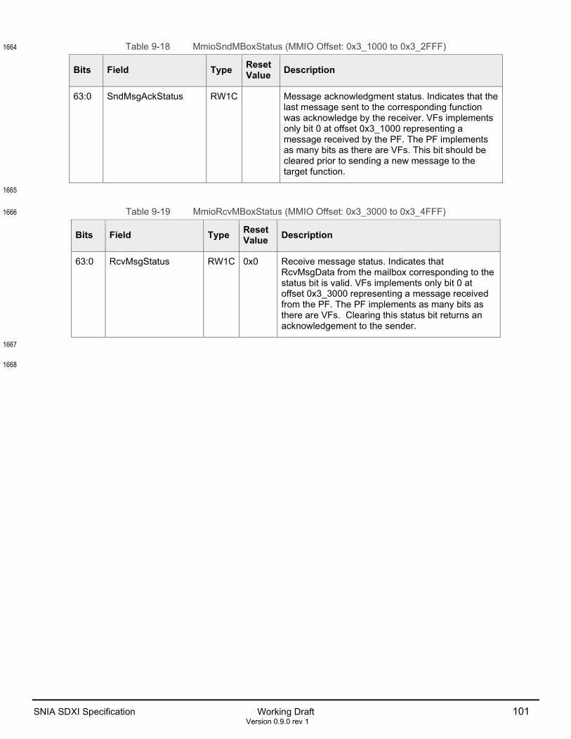
SNIA SDXI Specification Working Draft 101 Version 0.9.0 rev 1
Table 9-18 MmioSndMBoxStatus (MMIO Offset: 0x3_1000 to 0x3_2FFF) 1664
Bits Field Type Reset Value Description
63:0 SndMsgAckStatus RW1C Message acknowledgment status. Indicates that the last message sent to the corresponding function was acknowledge by the receiver. VFs implements only bit 0 at offset 0x3_1000 representing a message received by the PF. The PF implements as many bits as there are VFs. This bit should be cleared prior to sending a new message to the target function.
1665
Table 9-19 MmioRcvMBoxStatus (MMIO Offset: 0x3_3000 to 0x3_4FFF) 1666
Bits Field Type Reset Value Description
63:0 RcvMsgStatus RW1C 0x0 Receive message status. Indicates that RcvMsgData from the mailbox corresponding to the status bit is valid. VFs implements only bit 0 at offset 0x3_3000 representing a message received from the PF. The PF implements as many bits as there are VFs. Clearing this status bit returns an acknowledgement to the sender.
1667
1668

102 Working Draft SNIA SDXI Specification Version 0.9.0 rev 1
9.5 PF Mailbox Data Registers 1669
Table 9-20 Send Mailbox Data Format 1670
Bits Field Type Reset Value Description
127:0 SndMsgData RW 16 bytes of mailbox message data to be sent to a VF.
1671
Table 9-21 Receive Mailbox Data Format 1672
Bits Field Type Reset Value Description
127:0 RcvMsgData R 16 bytes of mailbox message data received from a VF.
1673
Table 9-22 MMIO Send Mailbox Registers 1674
MMIO Addresses MMIO Send Mailbox Range 0x06_0000 to 0x06_FFFF MmioSndMBox[0000:0FFF]
0x08_0000 to 0x08_FFFF MmioSndMBox[1000:1FFF]
0x0A_0000 to 0x0A_FFFF MmioSndMBox[2000:2FFF]
0x0C_0000 to 0x0C_FFFF MmioSndMBox[3000:3FFF]
0x0E_0000 to 0x0E_FFFF MmioSndMBox[4000:4FFF]
0x10_0000 to 0x10_FFFF MmioSndMBox[5000:5FFF]
0x12_0000 to 0x12_FFFF MmioSndMBox[6000:6FFF]
0x14_0000 to 0x14_FFFF MmioSndMBox[7000:7FFF]
0x16_0000 to 0x16_FFFF MmioSndMBox[8000:8FFF]
0x18_0000 to 0x18_FFFF MmioSndMBox[9000:9FFF]
0x1A_0000 to 0x1A_FFFF MmioSndMBox[A000:AFFF]
0x1C_0000 to 0x1C_FFFF MmioSndMBox[B000:BFFF]
0x1E_0000 to 0x1E_FFFF MmioSndMBox[C000:CFFF]
0x20_0000 to 0x20_FFFF MmioSndMBox[D000:DFFF]
0x22_0000 to 0x22_FFFF MmioSndMBox[E000:EFFF]
0x24_0000 to 0x24_FFFF MmioSndMBox[F000:FFFF]
1675
1676
1677

SNIA SDXI Specification Working Draft 103 Version 0.9.0 rev 1
Table 9-23 MMIO Receive Mailbox Registers 1678
MMIO Addresses MMIO Receive Mailbox Range 0x07_0000 to 0x07_FFFF MmioRcvMBox[0000:0FFF]
0x09_0000 to 0x09_FFFF MmioRcvMBox[1000:1FFF]
0x0B_0000 to 0x0B_FFFF MmioRcvMBox[2000:2FFF]
0x0D_0000 to 0x0D_FFFF MmioRcvMBox[3000:3FFF]
0x0F_0000 to 0x0F_FFFF MmioRcvMBox[4000:4FFF]
0x11_0000 to 0x11_FFFF MmioRcvMBox[5000:5FFF]
0x13_0000 to 0x13_FFFF MmioRcvMBox[6000:6FFF]
0x15_0000 to 0x15_FFFF MmioRcvMBox[7000:7FFF]
0x17_0000 to 0x17_FFFF MmioRcvMBox[8000:8FFF]
0x19_0000 to 0x19_FFFF MmioRcvMBox[9000:9FFF]
0x1B_0000 to 0x1B_FFFF MmioRcvMBox[A000:AFFF]
0x1D_0000 to 0x1D_FFFF MmioRcvMBox[B000:BFFF]
0x1F_0000 to 0x1F_FFFF MmioRcvMBox[C000:CFFF]
0x21_0000 to 0x21_FFFF MmioRcvMBox[D000:DFFF]
0x23_0000 to 0x23_FFFF MmioRcvMBox[E000:EFFF]
0x25_0000 to 0x25_FFFF MmioRcvMBox[F000:FFFF]
1679

104 Working Draft SNIA SDXI Specification Version 0.9.0 rev 1
9.6 VF Mailbox Data Registers 1680
Table 9-24 MmioSndMBoxData (MMIO Offset: 0x6_0000) 1681
Bits Field Type Reset Value Description
127:0 SndMsgData RW 16 bytes of mailbox message data to be sent to the PF.
1682
Table 9-25 MmioRcvMBoxData (MMIO Offset: 0x7_0000) 1683
Bits Field Type Reset Value Description
127:0 RcvMsgData R 16 bytes of mailbox message data received from the PF.
1684

SNIA SDXI Specification Working Draft 105 Version 0.9.0 rev 1
9.7 Doorbell BAR 1685
The doorbell BAR is used by software to indicate that new work is available within a particular context. The 1686 BAR is divided into doorbell stride size sections. Each section, numbered from zero, corresponds to the 1687 context of the same number. This spacing is provided to allow the doorbell region for a particular context 1688 to be mapped to a user process with MMU-based page protections. 1689
Currently only the lower 8 bytes within each section are allocated. Software performs an aligned 64b 1690 MMIO write containing the WriteIndex of the context to its associated doorbell address after new 1691 descriptors have been written to memory and after the WriteIndex value referenced by the context control 1692 entry has been updated. All other offsets within the doorbell BAR are reserved. 1693
Doorbell writes containing the value 0xFFFF_FFFF_FFFF_FFFF are special and signal the function that a 1694 context may have descriptors to process, but that the WriteIndex value needs to be fetched from memory. 1695
Reads to the doorbell BAR always return all-zero. The write pointer values cannot be read back through 1696 the doorbell BAR. They can only be read through the context entry. 1697
The size of the doorbell BAR is dependent on the maximum supported <doorbell stride> and the maximum 1698 number of ring contexts supported. 1699