smallsat thermal mgmt paper bugby j
TRANSCRIPT

SSC07-X-11
Bugby 1 21st Annual AIAA/USU
Conference on Small Satellites
Multi-Evaporator Hybrid Two-Phase Loop Cooling System for Small Satellites
David C. Bugby
ATK Space
5050 Powder Mill Road, Beltsville, MD 20705
ABSTRACT
This paper describes a small satellite thermal control architecture based on the multi-evaporator hybrid loop heat
pipe (ME-HLHP), a two-phase loop cooling system that combines capillary pumped loop (CPL) and loop heat pipe
(LHP) functionalities. The cooling system incorporates multiple heat load sharing evaporators for cooling/heating
remote (or nearby) components, dual counter-flow freeze-tolerant condensers for reduced attitude dependence, and
miniaturized Teflon wick evaporators for minimum control power. With concomitant functionalities like heat load
sharing and thermal diode action, this system can better meet the needs of future extended eclipse/limited power
small satellite missions compared to the traditional "cold-biasing plus heater power" approach. Extensive ME-HLHP
ground testing has been performed to demonstrate the capabilities of the system for future small satellite missions.
This paper will review the design/testing of this and five additional ground-based ME-HLHP cooling systems.
INTRODUCTION
The traditional spacecraft thermal design approach of
sizing radiators for the "hot case" and using heater
power for the "cold case" will not suffice for future
smallsat missions with large temperature extremes and
stringent power/mass limitations. Thus, NASA initiated
the ST-8 research effort several years ago to develop a
new thermal management system (TMS) for small
satellites.1 One of the initial ST-8 studies, which is the
subject of this paper, resulted in the first-ever ground
test of a miniaturized multi-evaporator hybrid loop heat
pipe (ME-HLHP) cooling system.2 In the three years
since that study concluded, five additional ME-HLHP
based cooling systems have been successfully ground
tested. This paper will describe the design/testing of
each cooling system and outline an implementation of a
centralized ME-HLHP thermal bus for a small satellite.
BACKGROUND
The ST-8 program goal was a TMS that would enable
component placement flexibility, minimize power/
mass/volume, improve power resource efficiency, and
be scalable up/down from 150 kg, 200 W. The features
necessary to meet those objectives included a multi-
evaporator bus, heat load sharing (HLS), miniaturized
components, thermal diode action, multiple condensers,
set-point controllability, and high conductance. The
TMS that could best provide those features was a multi-
evaporator two-phase loop. The available two-phase
loop architectures included the capillary pumped loop
(CPL), loop heat pipe (LHP), and hybrid loop heat pipe
(HLHP). Although CPLs/LHPs had a TRL head start,
as several CPLs and numerous LHPs are now on-orbit,
the HLHP had features that made it the best choice.
Two-Phase Loop Architectures
Due to its remote reservoir design, as shown in Figure 1,
the HLHP architecture is more like that of a CPL than it
is like that of an LHP. Thus, the HLHP has excellent
temperature controllability/expandability. The LHP,
though, with its adjacent-to-evaporator reservoir design,
sacrifices controllability/expandability for robustness.
A secondary wick between the LHP evaporator and
reservoir allows it to manage high "back conduction"
heat leaks in high pumping metal wicks. CPLs must
depend on inlet liquid subcooling to manage back
conduction and thus are limited to low conductivity,
low pumping polymer wicks. The HLHP overcomes the
CPL wick limitation by using a sweepage evaporator to
create an auxiliary flow that sweeps vapor/heat from the
primary evaporator cores. The HLHP thus provides
CPL expandability/controllability and LHP robustness.
Figure 1: CPL, LHP, and HLHP Architectures
LIQUID
HEAT INPUT
CONDENSERSHUNT
SEC. EVAPRESERVOIR
4-Port Evaporator
HEAT REJECTION
VAPOR
SET-POINT
HEATERSWEEPAGE
HEATER
Sweepage FlowLIQUID
HEAT INPUT
CONDENSERSHUNT
SEC. EVAPRESERVOIR
4-Port Evaporator
HEAT REJECTION
VAPOR
SET-POINT
HEATERSWEEPAGE
HEATER
Sweepage Flow
CPL
LHP
HLHP
SSC07-X-11
Bugby 2 21st Annual AIAA/USU
Conference on Small Satellites
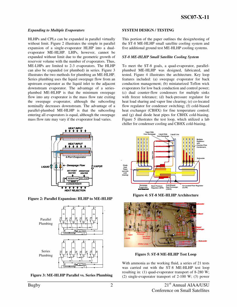
Expanding to Multiple Evaporators
HLHPs and CPLs can be expanded in parallel virtually
without limit. Figure 2 illustrates the simple in parallel
expansion of a single-evaporator HLHP into a dual-
evaporator ME-HLHP. LHPs, however, cannot be
expanded without limit due to the geometric growth of
reservoir volume with the number of evaporators. Thus,
ME-LHPs are limited to 2-3 evaporators. The HLHP
can also be expanded (or plumbed) in series. Figure 3
illustrates the two methods for plumbing an ME-HLHP.
Series plumbing uses the liquid sweepage flow from an
upstream evaporator as the liquid inlet to the adjacent
downstream evaporator. The advantage of a series-
plumbed ME-HLHP is that the minimum sweepage
flow into any evaporator is the mass flow rate exiting
the sweepage evaporator, although the subcooling
nominally decreases downstream. The advantage of a
parallel-plumbed ME-HLHP is that the subcooling
entering all evaporators is equal, although the sweepage
mass flow rate may vary if the evaporator load varies.
HEAT INPUT
4-Port Evaporator
LIQUID
HEAT INPUT
CONDENSERSHUNT
SEC. EVAPRESERVOIR
4-Port Evaporator
HEAT REJECTION
VAPOR
SET-POINT
HEATERSWEEPAGE
HEATER
Sweepage Flow
HEAT INPUT
4-Port Evaporator
LIQUID
HEAT INPUT
CONDENSERSHUNT
SEC. EVAPRESERVOIR
4-Port Evaporator
HEAT REJECTION
VAPOR
SET-POINT
HEATERSWEEPAGE
HEATER
Sweepage Flow
Figure 2: Parallel Expansion: HLHP to ME-HLHP
SERIES
V
L L
TPSP
V
E1
SP SPTP TP
V
SPTP
L L
V
E3 E4
SE
E2
C
R
PARALLEL
V
L L
TPSP
V
E1
SP SPTP TP
V
SPTP
L L
V
E3 E4
SE
E2
C
R
Series
Plumbing
Parallel
Plumbing
Figure 3: ME-HLHP Parallel vs. Series Plumbing
SYSTEM DESIGN / TESTING
This portion of the paper outlines the design/testing of
the ST-8 ME-HLHP small satellite cooling system and
five additional ground test ME-HLHP cooling systems.
ST-8 ME-HLHP Small Satellite Cooling System
To meet the ST-8 goals, a quad-evaporator, parallel-
plumbed ME-HLHP was designed, fabricated, and
tested. Figure 4 illustrates the architecture. Key loop
features included: (a) sweepage evaporator for back
conduction management; (b) miniaturized Teflon wick
evaporators for low back conduction and control power;
(c) dual counter-flow condensers for multiple sinks
with freeze tolerance; (d) back-pressure regulator for
heat load sharing and vapor line clearing; (e) co-located
flow regulator for condenser switching; (f) cold-biased
heat exchanger (CBHX) for fine temperature control;
and (g) dual diode heat pipes for CBHX cold-biasing.
Figure 5 illustrates the test loop, which utilized a lab
chiller for condenser cooling and CBHX cold-biasing.
Figure 4: ST-8 ME-HLHP Architecture
Counter-FlowCondenser 2
SweepageSight Glasses
Liquid
Counter-FlowCondenser 1
EVAP 3(Heat Load Sharing)
Single-PhaseSweepage
Vapor
EVAP 1
Cold-BiasedHeat Exchanger(CBHX)
EVAP 2EVAP 4
SecondaryEvaporator
Chiller Lines
Reservoir Shunt
BPR
Subcooler
Subcooler
Reservoir
Two-PhaseSweepage
Counter-FlowCondenser 2
SweepageSight Glasses
Liquid
Counter-FlowCondenser 1
EVAP 3(Heat Load Sharing)
Single-PhaseSweepage
Vapor
EVAP 1
Cold-BiasedHeat Exchanger(CBHX)
EVAP 2EVAP 4
SecondaryEvaporator
Chiller Lines
Reservoir Shunt
BPR
Subcooler
Subcooler
Reservoir
Two-PhaseSweepage
Figure 5: ST-8 ME-HLHP Test Loop
With ammonia as the working fluid, a series of 21 tests
was carried out with the ST-8 ME-HLHP test loop
resulting in: (1) quad-evaporator transport of 8-280 W;
(2) single-evaporator transport of 2-100 W; (3) power
Sweepage
Heater
Sat. Temp.Heater
Thermal StorageUnit (TSU)
Thermal StorageUnit (TSU)
EVAP 3 (PTFE WICK )
EVAP 1 (PTFE WICK )
EVAP 4 (PTFE WICK )
EVAP 2 (PTFE WICK )
SecondaryEvaporator/Reservoir
Vap
or
Lin
e
Diode
HeatPipes
(provide cold-
biasing)
Liquid Side
Core Sweepage
Co-Located Flow Regulator(CLFR)
Vapor Side
Core Sweepage Liquid Line
Subcooler
Multiple Radiators
withCounter-Flow
Condensers
Back Pressure
Regulator (BPR)
Cold-Biased Heat Exchanger
(CBHX)
Sweepage
Evaporator and Reservoir
Thermal Storage
Unit (TSU)
Thermal Storage
Unit (TSU)
EVAP 3 (PTFE WICK )
EVAP 1 (PTFE WICK )
EVAP 4 (PTFE WICK )
EVAP 2 (PTFE WICK )
SecondaryEvaporator/Reservoir
Vap
or
Lin
e
Diode
HeatPipes
(provide cold-
biasing)
Liquid Side
Core Sweepage
Co-Located Flow Regulator(CLFR)
Vapor Side
Core Sweepage Liquid Line
Subcooler
Multiple Radiators
withCounter-Flow
Condensers
Back Pressure
Regulator (BPR)
Cold-Biased Heat Exchanger
(CBHX)
Sweepage
Evaporator and Reservoir
KEY FEATURES
for negligible back conduction and low control power
Sweepage evaporator/reservoir enables
core sweepage to manage back conduction
biased heat exchanger (CBHX) for
Back pressure regulator (BPR) for heat
load sharing, vapor line clearing
located flow regulator (CLFR) for switching between multiple radiators
flow condensers for freeze
tolerance (if no spot heating)

SSC07-X-11
Bugby 3 21st Annual AIAA/USU
Conference on Small Satellites
cycling from 50-200 W; (4) maximum heat flux of 30
W/cm2; (5) conductance of 5-8 W/K per evaporator; (6)
heat load sharing greater than 95%; (7) successful
condenser switching; (8) freeze-tolerant condenser
(liquid exited at saturation); (9) temperature control of
+/- 0.25 K with a variable set-point; (10) rapid 30
minute start-up; (11) low secondary evaporator control
power of 4W; (12) loop isolation/diode action; and (13)
Teflon evaporator 233-353 K temperature cycling.
Selected test results are provided in Figures 6-10, which
respectively illustrate the power cycling, heat load
sharing, reservoir set-point control, heat transport limit,
and loop isolation test results.
10
15
20
25
30
35
40
18:30 19:00 19:30 20:00 20:30 21:00 21:30 22:00
Time [hh:mm]
Te
mp
era
ture
[C
]
0
50
100
150
200
250
300
He
at
Lo
ad
[W
]
Reservoir inlet (1) Reservoir (4) 2nd pump (6) BPR outlet (14)
FR outlet (43) Liquid line (45) E2 body (52) E3 body (57)
liquid sweepage line (68) vapor sweepage line (73) ambient (80) 2nd pump [W]
E2 Power [W] E3 power [W] Total Evap Power [W]
Figure 6: ST-8 Power Cycling
-5
0
5
10
15
20
25
30
35
10:00 11:00 12:00 13:00 14:00 15:00 16:00 17:00 18:00 19:00 20:00
Time [hh:mm]
Te
mp
era
ture
[C
]
0
25
50
75
100
125
150
175
200
He
at
Lo
ad
[W
]
Reservoir inlet (1) Reservoir (4) 2nd pump (6) BPR outlet (14)
FR outlet (43) Liquid line (45) E1 body (48) E2 body (53)
E3 body (57) E4 body (62) liquid sweepage line (68) vapor sweepage line (73)
ambient (80) Q-meter (82) Q-meter (83) 2nd pump [W]
E1 Power [W] E2 Power [W] E3 power [W] Total Evap Power [W]
Figure 7: ST-8 Heat Load Sharing
10
15
20
25
30
35
40
45
6:00 6:30 7:00 7:30 8:00 8:30
Time [hh:mm]
Te
mp
era
ture
[C
]
0
50
100
150
200
250
300
350
He
at
Lo
ad
[W
]
Reservoir inlet (1) Reservoir (4) 2nd pump (6) BPR outlet (14)
FR outlet (43) Liquid line (45) E2 body (52) E3 body (57)
liquid sweepage line (68) vapor sweepage line (73) ambient (80) 2nd pump [W]
E2 Power [W] E3 power [W] Total Evap Power [W]
Reservoir
Primary Evaporators
FR outlet
Figure 8: ST-8 Reservoir Set-Point Control
10
20
30
40
50
60
15:00 15:30 16:00 16:30 17:00 17:30 18:00 18:30
Time [hh:mm]
Te
mp
era
ture
[C
]
0
100
200
300
400
500
He
at
Lo
ad
[W
]
Reservoir inlet (1) Reservoir (4) 2nd pump (6) BPR outlet (14)
FR outlet (43) Liquid line (45) E2 body (52) E3 body (57)
vapor sweepage line (73) ambient (80) 2nd pump [W] E2 Power [W]
E3 power [W] Total Evap Power [W]
Figure 9: ST-8 Heat Transport Limit
-40
-30
-20
-10
0
10
20
30
40
50
7:00 8:00 9:00 10:00 11:00 12:00 13:00 14:00 15:00 16:00 17:00
Time [hh:mm]
Te
mp
era
ture
[C
]
0
25
50
75
100
125
150
175
200
225
He
at
Lo
ad
[W
]
Reservoir inlet (1) Reservoir (4) 2nd pump (6) BPR outlet (14)
Liquid line (45) E1 body (47) E2 body (52) E3 body (58)
E4 body (62) ambient (80) Cond #2 (25) Total Evap Power [W]
Figure 10: ST-8 Loop Isolation
ST-8 Status. One of the major accomplishments during
this 6-month ST-8 study was the development of a
miniaturized Teflon wick 4-port evaporator. Figure 11
illustrates this novel design, which features a 0.64 cm
outer diameter wick. Moreover, all 21 tests conducted
were highly successful. Despite this success, NASA did
not select the ME-HLHP small satellite cooling system
for the ST-8 flight experiment. A dual-evaporator ME-
LHP with TEC reservoir cold biasing was selected
instead.4 However, that selection elicits concerns such
as: (a) the risk of expanding beyond two evaporators;
and (b) the impact of TEC failure on loop temperature
controllability. Although these two issues are not
concerns for the ME-HLHP, flight verification still is.
Thus, a flight test to verify the ME-HLHP architecture
in zero-g, preferably with 4-6 evaporators, is needed
before future flight implementations are likely.
Figure 11: Miniaturized Teflon Wick Evaporator

SSC07-X-11
Bugby 4 21st Annual AIAA/USU
Conference on Small Satellites
Additional ME-HLHP Cooling Systems
Five additional ME-HLHP cooling systems have been
successfully ground-tested since the conclusion of the
ST-8 study three years ago. These systems include the
following applications: (1) moderate flux laser; (2) high
flux laser; (3) large spacecraft; (4) rack electronics; and
(5) intermittent power instrument. The five applications
are discussed below. A summary table with key data on
each test system is provided later in the paper.
Moderate Flux Laser. The problem addressed in this
program was the cooling of a moderate flux (30 W/cm2)
laser crystal with a sub-ambient operating temperature.
The solution was an ammonia ME-HLHP with four
evaporators mounted in an Al heat sink and a liquid
cooled shield (LCS). The LCS is a self-cooling two-
phase loop plumbing feature originally developed to
enable the cryogenic CPL.3 Figure 12 illustrates the
architecture and Figure 13 illustrates the test loop. In
lab testing with a test heater, the cooling system met the
requirements for heat flux, operating temperature, and
heat sink uniformity. In testing at the customer site, the
cooling system was successfully integrated with a
working laser. Crystal waste heat was quantified by
turning the diode array off and applying power to a
Kapton heat sink heater and then matching the liquid
inlet temperature, creating an in-situ Q-meter.
Four Parallel Condenser Lines
Flow Regulator (4)
Liquid Header
Condenser Vapor Header
Back Pressure Regulator (BPR) Secondary Evaporator
Reservoir
Evaporator Mounting Plate(Four parallel four-port evaporators)
Liquid Cooled Shield (LCS)
Vapor Line
Figure 12: Laser Crystal Cooling Architecture
SecondaryEvaporator
Condenser
LCS
4 Primary Evaporators in Al Heat Sink
Vapor
Header
Reservoir
Flow
Reg.
Liquid
Header
Alum.
Shunt
SecondaryEvaporator
Condenser
LCS
4 Primary Evaporators in Al Heat Sink
Vapor
Header
Reservoir
Flow
Reg.
Liquid
Header
Alum.
Shunt
Figure 13: Laser Crystal Cooling Test Loop
High Flux Laser. The problem addressed during this
program was the cooling of multiple low profile heat
sources in a high power/high flux laser system. The
solution was a dual-evaporator ammonia ME-HLHP
with: (a) innovative inlet/outlet ports to enable the
cooling of multiple low profile heat sources; (b) series
plumbing; and (c) a mechanical pump (no sweepage
evaporator). Figure 14 illustrates the architecture and
Figure 15 illustrates the test loop. In lab testing with a
test heater, the system successfully operated in the
"flow-through" mode with a total heat load of 880 W on
the evaporators heated from one side. The system was
designed for two-sided heating of the evaporators (0.64
cm wick OD) and a total heat load of 1600 W. Other
key results are as follows: (1) system operated below
ambient due to high mass flow rate (sub-ambient
operation is possible even at 0 W due to the mechanical
pump); (2) target heat flux of 50 W/cm2 was achieved
with single-sided heat input (system was designed for
two-sided heat input); and (3) successful operation with
0-450 W and 0-224 W power cycling.
1
2
3
5
4
6
78
9
10
11
12
13
1415
1617
1
2
3
5
4
6
78
9
10
11
12
13
1415
1617
1. Mechanical Pump2. Filter3. Calorimeter4. Evaporator 1
5. Evaporator 26. Evap 1-2 Liquid Line7. Vapor Line
8. Condenser9. Reservoir 10. Sweepage Valve
11. Reservoir Chiller/Shunt12. Chiller Path 213. Chiller Path 214. Chiller Path 1
15. Chiller Path 116. DP Transducer17. Fill Tube
Figure 14: High Flux Laser Cooling Architecture
Figure 15: High Flux Laser Cooling Test Loop
Large Spacecraft. The cooling of very high power (up
to 100 kW) next-generation military spacecraft is the
problem addressed by the Dual-Use Science and
Technology (DUS&T) program, conducted jointly with
AFRL/PRP. The solution involves a mechanical pump
assisted ammonia ME-HLHP with the ability to
smoothly transition from capillary to mechanical
pumping. The program was conducted in two phases.

SSC07-X-11
Bugby 5 21st Annual AIAA/USU
Conference on Small Satellites
During the first phase, a 3-evaporator 2 kW risk-
reduction test bed was designed, fabricated, and tested.
The results from the 2 kW system provided guidance to
design a 10 kW test bed for the second phase, which is
configured as follows: (1) 6 low impedance
evaporators; (2) series plumbing with parallel as an
option; (3) 4-port evaporators with 3-port evaporators
as a valving-enabled option; (4) mechanical pumping
with capillary-only pumping as an option; and (5) large
spacecraft features that include evaporator-condenser
separation of 5 m and evaporator elevation differences
of 3 m. Figures 16 and 17, respectively, show a block
diagram and a photo of the 10 kW test bed. Results for
the 10 kW system will be published shortly.
132”
V1
V18
V3
V11
V7
V12
Pressure Transducer (4)
V6
V5
Sight Glass (2)
V13 V16 V10
V15V9
V8V14
V4
V2
V17
Flowmeter Mechanical Pump
Filter
Subcooler
Condenser Plate (3)
E1SN010
E2SN006
E3SN012
E4SN011
E5SN008
E6SN007
Vap
or
Lin
e 93
”
Liquid Line 93”
Liquid Line 93”
Sweepage Line 93”
bonded saddle next to pump body)
Vapor Sweepage Line 93”
Sweepage Line 93”
V19
V20
Heater Blocks
Coolant Block
Figure 16: Schematic of 10 kW Test Bed
Figure 17: Photo of the 10 kW Test Bed
Rack Electronics. In conjunction with TA&T, this
Navy SBIR program addressed the problem of rack
electronics cooling on Navy ships/submarines. In
particular, since air-cooling is nearing its limits, and is
an acoustic noise source for submarines, an alternative
was sought. The solution was two-pronged: (1) box-
mounted water ME-HLHP cooling loops; and (2) rack-
mounted single-phase water-cooling loop with "wedge"
interfaces. Figure 18 illustrates the solution. Figure 19
illustrates the ME-HLHP test loop. Figure 20 illustrates
the wedge interface system. The results from this effort
are as follows: (1) 100 W heat load on each evaporator
(300 W total) with 5 W on the secondary evaporator;
(2) loop saturation temperature of 328 K; and (3) end-
to-end conductance was 9 W/K (305 W, 348 K heater,
313K chiller). Future work will involve installation and
testing of (derivative) single-evaporator LHPs with
ceramic wicks and air-cooled condensers. This alternate
approach will hasten system implementation given
infrastructure resistance to implementing rack cooling.
Figure 18: Rack Electronics Cooling Solution
Flat PlateFlat Plate
Figure 19: Water ME-HLHP
Figure 20: Wedge Condenser System
Elevation Control
Hinges/Flex Lines
3 Evaporators 1m
Below Condenser
3 Evaporators 2m
Above Condenser
Condenser
SERVERIN RACK
WEDGE
RECEIVER
WEDGE
WEDGE CONDENSER
SCREWTIGHTENED
TO FINALIZECONNECTION
WEDGE
MATES TORECEIVER
SSC07-X-11
Bugby 6 21st Annual AIAA/USU
Conference on Small Satellites
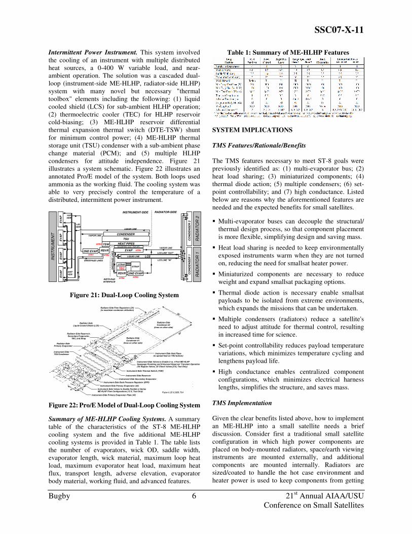
Intermittent Power Instrument. This system involved
the cooling of an instrument with multiple distributed
heat sources, a 0-400 W variable load, and near-
ambient operation. The solution was a cascaded dual-
loop (instrument-side ME-HLHP, radiator-side HLHP)
system with many novel but necessary "thermal
toolbox" elements including the following: (1) liquid
cooled shield (LCS) for sub-ambient HLHP operation;
(2) thermoelectric cooler (TEC) for HLHP reservoir
cold-biasing; (3) ME-HLHP reservoir differential
thermal expansion thermal switch (DTE-TSW) shunt
for minimum control power; (4) ME-HLHP thermal
storage unit (TSU) condenser with a sub-ambient phase
change material (PCM); and (5) multiple HLHP
condensers for attitude independence. Figure 21
illustrates a system schematic. Figure 22 illustrates an
annotated Pro/E model of the system. Both loops used
ammonia as the working fluid. The cooling system was
able to very precisely control the temperature of a
distributed, intermittent power instrument.
LCS LINE "OUT"
CO
ND
EN
SE
R 1
TSU
EV
AP
CO
ND
EN
SE
R 2
CONDENSER
HEAT PIPES
EVAP2ND EVAP
TSW
RSVR
RSVR 2ND EVAP
STRAP
TECSTRAP
EV
AP
EV
AP
EV
AP
INS
TR
UM
EN
T
RA
DIA
TO
R 2
INSTRUMENT-SIDE
INSTR-RADINTERFACE
LCS
RA
DIA
TO
R 1
SOLDERED (LOC. FOR HP)
SW
EE
PA
GE
LIN
ES
VAPOR LINE
LIQHDR
LCS LINE "IN"
LIQUID LINE
LIQUID LINE
VAPOR LINE
SWEEPAGE LINES
SWPHDR
VAPHDR
HTR1 HTR2
HTR3
HTR4
RADIATOR-SIDE
HTR5HTR6
Figure 21: Dual-Loop Cooling System
Instrument-Side Valves to Enable 3 vs. 4 Port ME-HLHP
Sweepage Plumbing and Enhanced Reservoir Transient Operation(5X Regular Valves, 2X Check Valves [CV], Test Only)
Radiator-Side
Condenser #2
(lines on other side)
Instrument-Side Secondary Evaporator
Instrument-Side Primary Evaporator Plate (4X)
Instrument-Side Reservoir
Subcooler for C
ondenser #2
Radiator-Side
Condenser #1
(lines on other side)
Radiator-Side Reservoir,
Secondary Evaporator,TEC, and Strap
Instrument-SideTSU/Condenser
Radiator-SidePrimary Evaporator
Instrument-Side Thermal Switch (TSW)
Radiator-Side Flow Regulators (2X)(to maximize condenser utilization)
Radiator-Side
Liquid-Cooled Shield (LCS)
Instrument-Side Heat Pipes(to spread heat on TSU bottom)
Subcooler for C
ondenser #1
Instrument-Side Back Pressure Regulator (BPR)
6"
20"
6"
20"
Instrument-Side Valves to Enable Parallel or SeriesME-HLHP Flow Configurations (12 X, Test Only)
CV
CV
Instrument-Side Primary Evaporator (4X)
Patent US 6,889,754
Figure 22: Pro/E Model of Dual-Loop Cooling System
Summary of ME-HLHP Cooling Systems. A summary
table of the characteristics of the ST-8 ME-HLHP
cooling system and the five additional ME-HLHP
cooling systems is provided in Table 1. The table lists
the number of evaporators, wick OD, saddle width,
evaporator length, wick material, maximum loop heat
load, maximum evaporator heat load, maximum heat
flux, transport length, adverse elevation, evaporator
body material, working fluid, and advanced features.
Table 1: Summary of ME-HLHP Features
SYSTEM IMPLICATIONS
TMS Features/Rationale/Benefits
The TMS features necessary to meet ST-8 goals were
previously identified as: (1) multi-evaporator bus; (2)
heat load sharing; (3) miniaturized components; (4)
thermal diode action; (5) multiple condensers; (6) set-
point controllability; and (7) high conductance. Listed
below are reasons why the aforementioned features are
needed and the expected benefits for small satellites.
� Multi-evaporator buses can decouple the structural/
thermal design process, so that component placement
is more flexible, simplifying design and saving mass.
� Heat load sharing is needed to keep environmentally
exposed instruments warm when they are not turned
on, reducing the need for smallsat heater power.
� Miniaturized components are necessary to reduce
weight and expand smallsat packaging options.
� Thermal diode action is necessary enable smallsat
payloads to be isolated from extreme environments,
which expands the missions that can be undertaken.
� Multiple condensers (radiators) reduce a satellite's
need to adjust attitude for thermal control, resulting
in increased time for science.
� Set-point controllability reduces payload temperature
variations, which minimizes temperature cycling and
lengthens payload life.
� High conductance enables centralized component
configurations, which minimizes electrical harness
lengths, simplifies the structure, and saves mass.
TMS Implementation
Given the clear benefits listed above, how to implement
an ME-HLHP into a small satellite needs a brief
discussion. Consider first a traditional small satellite
configuration in which high power components are
placed on body-mounted radiators, space/earth viewing
instruments are mounted externally, and additional
components are mounted internally. Radiators are
sized/coated to handle the hot case environment and
heater power is used to keep components from getting

SSC07-X-11
Bugby 7 21st Annual AIAA/USU
Conference on Small Satellites
too cold in the cold case. Figure 23 illustrates a layout
using the traditional thermal design approach. Figure 24
illustrates a centralized ME-HLHP using the Figure 23
architecture/components. In Figure 24, all components
except external viewing ones are coupled to a central
ME-HLHP bus, earth/space viewing components are
kept warm when OFF by HLS, and hot radiator soak-
back is small due to ME-HLHP diode action.
MLI Covers Non-Radiator Surfaces
High Power Components
Mounted On/Near Exterior(may need heater power when OFF)
Earth-Viewing ComponentsNeed Heater Power When OFF
Internal Components Coupled Conductively
and/or Radiatively to the Walls
Radiator 2
Sized/Coated
for Hot CaseIncluding
Hot Radiator 1
Space-Viewing Components
Need Heater Power When OFF
Radiator 1
Sized/Coatedfor Hot Case
IncludingHot Radiator 2
Figure 23. Traditional Small Satellite Design Layout
CBHX
All Components Except External Viewing Ones
Centrally Located Coupled to ME-HLHP Thermal Bus
Total MLI Coverage Except Protruding
Components, Lines, Standoffs
Radiator 1Sized/Coated for
Hot Case ... CanIgnore Impact ofHot Radiator 2
Subcooler 2
Radiator 2Sized/Coated for
Hot Case ... CanIgnore Impact ofHot Radiator 1
DHPto CBHX
Earth-Viewing ComponentsKept Warm When OFF by HLS
Space-Viewing ComponentsKept Warm When OFF by HLS
Subcooler 1 DHPto CBHX
Figure 24. Centralized ME-HLHP Satellite Design
CONCLUSIONS
This paper has described the design, fabrication, and
testing of a multi-evaporator thermal bus architecture
for small satellite thermal control. The basis for the
system is the multi-evaporator hybrid loop heat pipe
(ME-HLHP), a two-phase loop cooling system with
CPL/LHP underpinnings, but with key advantages over
each. This system was designed/built/tested as part of
the NASA ST-8 Phase A study from Jan-Jun 2004. At
that time, it was the first-ever ground test of a
miniaturized ME-HLHP cooling system. The design
and testing of five subsequent ME-HLHP based cooling
systems -- in the areas of laser, spacecraft, electronics,
and instrument cooling -- were also described. Although
the architecture has been clearly proven for ground
applications, to fully validate it for future smallsat
missions, an ME-HLHP flight experiment is needed.
ACKNOWLEDGMENTS
The author would like to gratefully acknowledge the
important contributions of the following individuals to
the work described herein: Matt Beres, Pete Cologer,
Jessica Kester, Dmitry Khrustalev, Steve Krein, Ed
Kroliczek, Chuck Stouffer, Dave Wolf, Kim Wrenn,
and James Yun.
REFERENCES
1. NASA New Millennium Program Space
Technology 8, NRA 03-OSS-02, February 2003.
2. Bugby, D., E. Kroliczek, and J. Yun, "Development
and Testing of a Miniaturized Multi-Evaporator
Hybrid Loop Heat Pipe," Space Technology
Applications International Forum (STAIF-05),
Albuquerque, NM, January, 2005.
3. Baumann, J., B. Cullimore, D. Bugby, and E.
Kroliczek, "Development of the Cryogenic
Capillary Pumped Loop," 33rd IECEC, IECEC-98-
I197, Colorado Springs, CO, August 1998.
4. Ku, J., L. Ottenstein, D. Douglas, M. Pauken, G.
Birur, "Miniature Loop Heat Pipe with Multiple
Evaporators for Thermal Control of Small
Spacecraft," Paper No. 183, 30th GOMACTech
Conference, Las Vegas, NV, April 2005.