small size precipitator for domestic biomass-furnaces
TRANSCRIPT
ICESP 2016, Wrocław, Poland, 19–23 September 2016
Small size precipitator for domestic biomass-furnaces
N. Grass1, T. Fischer²
1 Technische Hochschule Nuernberg, Kesslerplatz 12, 90489 Nuremberg ² Grass Power Electronics GmbH, Preisslerstr. 11, 90429 Nuremberg
Corresponding author: [email protected]
Abstract Domestic biomass furnaces are carbon neutral but are causing considerable amounts of particulate emissions. Electrostatic precipitators are known from industrial applications to clean combustion gases very efficiently. A prototype of a small size precipitator has been developed and tested on a commercial 30 kW wood chip boiler. After some considerations about collecting efficiency and mechanical construction, the main focus was on the design of the high voltage power supply, which has been be realized as a resonant converter in order to increase power efficiency and reduce voltage stress on the switching semiconductor devices. To ensure stable operation, a fast control algorithm was developed to react on electric breakdowns and accurately control the precipitator operation.
Keywords: Biomass, domestic furnaces, fuzzy logic, resonant inverters, high voltage power supply
1. Introduction With renewable energy becoming more important for domestic heating, there is an increasing particulate matter concentration in urban areas, resulting in a higher health risk for the people living in those areas. Particularly, the dust particles with a diameter smaller than 10 micrometers can cause serious diseases. Because of their small size, those particles do not tend to settle down to the ground by gravity, but can stay in the air for days or weeks, what makes an efficient precipitation process necessary. For this scope of application, the “Smart Home Precipitator” should meet the following requirements:
• Installation in both new built and existing furnaces;
• High collection efficiency; • Automatic adaption of control parameters to
different operating modes; • Low energy consumption; • Automatic cleaning of collection electrodes.
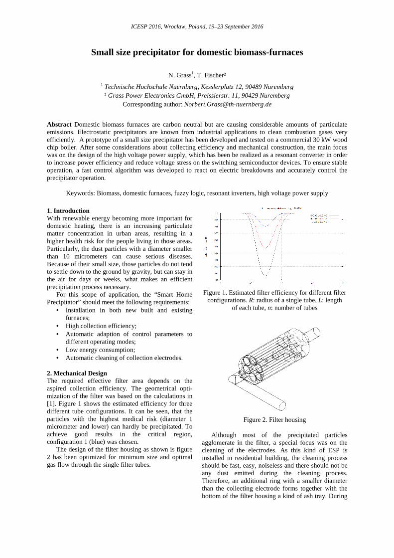
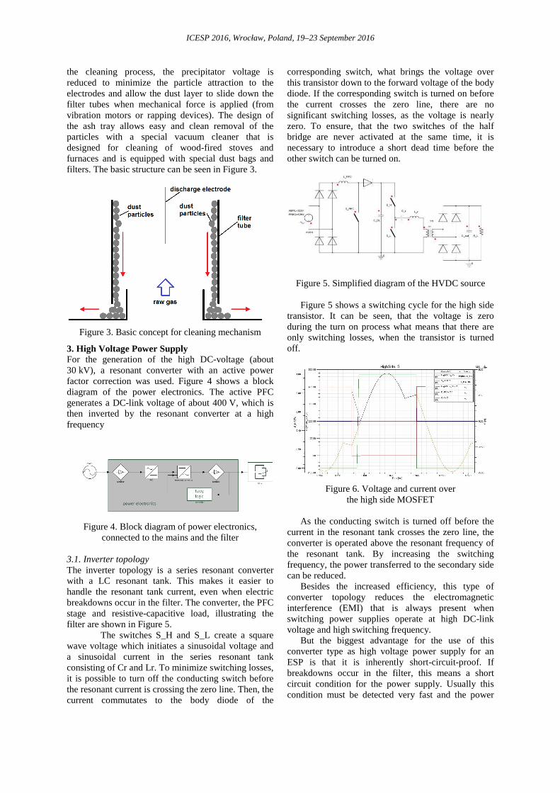
2. Mechanical Design The required effective filter area depends on the aspired collection efficiency. The geometrical opti-mization of the filter was based on the calculations in [1]. Figure 1 shows the estimated efficiency for three different tube configurations. It can be seen, that the particles with the highest medical risk (diameter 1 micrometer and lower) can hardly be precipitated. To achieve good results in the critical region, configuration 1 (blue) was chosen. The design of the filter housing as shown is figure 2 has been optimized for minimum size and optimal gas flow through the single filter tubes.
Figure 1. Estimated filter efficiency for different filter
configurations. R: radius of a single tube, L: length of each tube, n: number of tubes
Figure 2. Filter housing Although most of the precipitated particles agglomerate in the filter, a special focus was on the cleaning of the electrodes. As this kind of ESP is installed in residential building, the cleaning process should be fast, easy, noiseless and there should not be any dust emitted during the cleaning process. Therefore, an additional ring with a smaller diameter than the collecting electrode forms together with the bottom of the filter housing a kind of ash tray. During
ICESP 2016, Wrocław, Poland, 19–23 September 2016
the cleaning process, the precipitator voltage is reduced to minimize the particle attraction to the electrodes and allow the dust layer to slide down the filter tubes when mechanical force is applied (from vibration motors or rapping devices). The design of the ash tray allows easy and clean removal of the particles with a special vacuum cleaner that is designed for cleaning of wood-fired stoves and furnaces and is equipped with special dust bags and filters. The basic structure can be seen in Figure 3.
Figure 3. Basic concept for cleaning mechanism
3. High Voltage Power Supply For the generation of the high DC-voltage (about 30 kV), a resonant converter with an active power factor correction was used. Figure 4 shows a block diagram of the power electronics. The active PFC generates a DC-link voltage of about 400 V, which is then inverted by the resonant converter at a high frequency
Figure 4. Block diagram of power electronics, connected to the mains and the filter
3.1. Inverter topology The inverter topology is a series resonant converter with a LC resonant tank. This makes it easier to handle the resonant tank current, even when electric breakdowns occur in the filter. The converter, the PFC stage and resistive-capacitive load, illustrating the filter are shown in Figure 5.
The switches S_H and S_L create a square wave voltage which initiates a sinusoidal voltage and a sinusoidal current in the series resonant tank consisting of Cr and Lr. To minimize switching losses, it is possible to turn off the conducting switch before the resonant current is crossing the zero line. Then, the current commutates to the body diode of the
corresponding switch, what brings the voltage over this transistor down to the forward voltage of the body diode. If the corresponding switch is turned on before the current crosses the zero line, there are no significant switching losses, as the voltage is nearly zero. To ensure, that the two switches of the half bridge are never activated at the same time, it is necessary to introduce a short dead time before the other switch can be turned on.
Figure 5. Simplified diagram of the HVDC source
Figure 5 shows a switching cycle for the high side transistor. It can be seen, that the voltage is zero during the turn on process what means that there are only switching losses, when the transistor is turned off.
Figure 6. Voltage and current over
the high side MOSFET
As the conducting switch is turned off before the current in the resonant tank crosses the zero line, the converter is operated above the resonant frequency of the resonant tank. By increasing the switching frequency, the power transferred to the secondary side can be reduced. Besides the increased efficiency, this type of converter topology reduces the electromagnetic interference (EMI) that is always present when switching power supplies operate at high DC-link voltage and high switching frequency. But the biggest advantage for the use of this converter type as high voltage power supply for an ESP is that it is inherently short-circuit-proof. If breakdowns occur in the filter, this means a short circuit condition for the power supply. Usually this condition must be detected very fast and the power

ICESP 2016, Wrocław, Poland, 19–23 September 2016
supply has to be turned off for a short period to protect the switches from overcurrent situations. A short circuit condition in a resonant converter has a huge influence on the impedance of the resonant tank and detunes it in a way that the current in the resonant tank is limited. Figure 7 shows a breakdown at about 33 kV. The filter voltage goes down to zero but the converter keeps operating as it can be seen from the control signal for the high side switch. The current is no longer sinusoidal and a soft switching as described above can no longer be achieved. But the converter can be operated under these conditions long enough that the controller can decide if the spark that causes the breakdown quenches by itself or if the current needs to be interrupted for deionization of the fault path inside the precipitator.
Figure 7. Voltage breakdown and flashover response 3.2. High Voltage Transformer and Rectifier The design of the high voltage part of the circuit requires special attention, because the system size and cost depends to a high content from it. For thermal and voltage insulation issues, a cast resin type high frequency transformer with integrated full bridge rectifier has been developed. The transformer has been designed with four I-type ferrite cores, giving high flexibility for the mechanical setup. The primary and secondary coils are placed on opposing core ferrite elements to ensure proper isolation. Usually, this setup leads to a comparatively high leakage inductance in the transformer, causing voltage peaks and high stress on the semiconductor switches in a power supply. But with the described resonant converter topology, used in this project, the leakage inductance simply adds to the series inductor of the resonant tank. I.e., with a proper transformer design, the resonant inductor can be integrated in the transformer which helps to reduce both, size and cost for the power supply. The high voltage rectifier and both, the voltage and current measurement for the high voltage side have been integrated on one PCB from about the same size as the transformer. This makes it possible to cast all high voltage parts together in one compact part (Figure 8).
Figure 8. High voltage transformer and rectifier
3.3. Controller There are mainly two conditions that require a fast and well-tuned controller. The first one is the switching frequency. To reduce the size of the magnetic components in the circuit, the converter is operated at a high switching frequency of about 100 kHz. The second one is the problem that the filter has to be operated close to the point of electric breakdown to get the desired results for the collection efficiency. If such a breakdown happens, the controller must react immediately to prevent the converter from overload and to avoid local high ionization inside the precipitator. Figure 9 shows the output voltage of the converter controlled by a classic PID-controller tuned with the Ziegler-Nichols method. Thus, the voltage control was proven stable even for different precipitator design parameters and operating modes. The simulation shows an overshot at the startup followed by some oscillation ringing.
Figure 9. Simulated output voltage and current of the PID-controlled converter
Figure 10. Control results on different operating conditions

ICESP 2016, Wrocław, Poland, 19–23 September 2016
To improve the dynamic closed loop behavior, the controller will be developed in fuzzy logic. This type of controller is working with rules instead of precise mathematical model and is similar to the way how humans make decisions. This makes it easier to model nonlinearities such as electrical breakdowns or other very fast load changes. 4. Experimental results A test phase has been conducted on a 30 kW wood chip boiler for different operating conditions of the boiler. The collection efficiency was measured for both nominal load of the boiler and at partial load of about 50% heat output. To ensure the reproducibility of the measurements a standardized measurement method (VDI 2066) was applied.
Figure 11. Collection efficiency and power consumption at nominal load of the boiler
For the furnace operating at nominal load, the collection efficiency was measured at different filter voltages. Fig. 10 shows the results for voltages from 12 kV to 30 kV. It can be seen that a collection efficiency of more than 95% can be reached at 18 kV, what means a power consumption of about 10 W for this geometry. Increasing the filter voltage linearly leads expectably to an exponential increase of the power consumption with a comparably low effect on the collection efficiency. I.e. in this scope of applica-tion, where a collection efficiency of 90% is entirely sufficient, the power consumption is the next most important parameter that has to be optimized.
The measurements at partial load carried out that in this operating mode much more electrical power is needed to achieve a similar collection efficiency due to the rising amount of soot in the flue gas. To reach more than 95% collection efficiency with the boiler operating at 50% load, 140 W of electrical power were needed what is more than ten times the value for full load operation. As the boiler will run both under full load and partial load conditions when used for heat generation in households, it is absolutely necessary to find rules for optimization of both the collection efficiency and the power consumption at the same time. References [1] Zouzou N., Dascalescu L., "Comments on the
geometrical optimization of a small ESP". [2] Grass N., Fuzzy Logic-Optimizing IGBT
Inverter for Electrostatic Precipitators, Conference Proceedings IEEE IAS 1999 annual meeting, Phoenix, 4-7. Oct. 1999.
[3] Grass N., Application of different types of high voltage supplies on industrial electrostatics precipitators, IEEE Trans. Plasma Sci. Vol. 28, no. 5, 2000, pp. 1481-1485.
[4] Hausmann M., Grass N., Piepenbreier B., Power Electronic Modelling & Emulation of an Electrostatic Precipitator, ICESP XII conference proceedings.