small sensor ml-020s-o ml-020s-i...eko instruments co., ltd. small sensor ml-020...
TRANSCRIPT

INSTRUCTION MANUAL
ML-020PML-020S-OML-020S-I
Small Sensor

EKO INSTRUMENTS CO., LTD. Small Sensor ML-020 P/ML-020S-O/ML-020S-I Instruction Manual Ver.8 Pg. 1
1. Index
1. Index 1
2. Important User Information 2
2-1. Contact Information 2
2-2. Warranty and Liabi l i ty 2
2-3. About Instruct ion Manual 3
2-4. Environment 3
3. Safety Information 4
3-1. WARNING/CAUTION 4
4. Introduction 5
4-1. Main Features 5
4-2. Package Contents 5
5. Getting Started 6
5-1. Parts Name and Descr ipt ions 6
5-2. Setup 7
5-3. Cable Connect ion 9
5-5. Measurement 10
6. Maintenance & Troubleshooting 11
6-1. Maintenance 11
6-2. Cal ibrat ion Method 12
6-3. Troubleshoot ing 12
7. Specification 13
7-1. Main Uni t 13
7-2. Cables 13
7-3. Dimensions 14
7-4. Accessor ies List 15
APPENDIX 16
A-1. Spectral & Direct ional Response Character ist ics 16
A-2. Traceabi l i ty 17

EKO INSTRUMENTS CO., LTD. Small Sensor ML-020 P/ML-020S-O/ML-020S-I Instruction Manual Ver.8 Pg. 2
2. Important User Information
Thank you for using EKO Products
Make sure to read this instruction manual thoroughly and to understand the contents before starting to operate the
instrument. Keep this manual at safe and handy place for whenever it is needed.
For any questions, please contact us at one of the EKO offices given below:
2-1. Contact Informat ion
EKO INSTRUMENTS CO., LTD. Asia, Oceania Region
www.eko.co.jp
EKO INSTRUMETNS Co., Ltd.
1-21-8 Hatagaya, Shibuya-ku
Tokyo, 151-0072 Japan
Tel: +81 (3) 3469-6711
Fax: +81 (3) 3469-6719
Europe, Middle East, Africa, South America Region
www.eko-eu.com
EKO INSTRUMENTS Europe B.V.
Lulofsstraat 55, Unit 28,
2521 AL Den Haag, The Netherlands
Tel: +31 (0)70 3050117
Fax: +31 (0)70 3840607
North America Region
www.eko-usa.com
EKO INSTRUMENTS USA Inc.
111 North Market Street , Suite 300
San Jose, CA 95113 USA
Tel: +1 408-977-7751
Fax: +1 408-977-7741
2-2. Warranty and Liabi l i ty
For warranty terms and conditions, contact EKO or your distributor for further details.
EKO guarantees that the product delivered to customer has been verified, checked and tested to ensure that
the product meets the appropriate specifications. The product warranty is valid only if the product has been
installed and used according to the directives provided in this instruction manual.
In case of any manufacturing defect, the product will be repaired or replaced under warranty. However, the
warranty does not apply if:
Any modification or repair was done by any person or organization other than EKO service
personnel.
The damage or defect is caused by not respecting the instructions of use as given on the product
brochure or the instruction manual.

EKO INSTRUMENTS CO., LTD. Small Sensor ML-020 P/ML-020S-O/ML-020S-I Instruction Manual Ver.8 Pg. 3
2-3. About Instruct ion Manual
Copy Rights Reserved by EKO INSTRUMENTS CO., LTD. Making copies of whole or parts of this
document without permission from EKO is prohibited.
This manual was issued: 2018/3/9
Version Number: 8
2-4. Environment
1. WEEE Directive 2002/96/EC (Waste Electrical and Electronic Equipment)
This product is not subjected to WEEE Directive 2002/96/EC however it should not be mixed with general
household waste. For proper treatment, recovery and recycling, please take this product(s) to designated
collection points.
Disposing of this product correctly will help save valuable resources and prevent any potential negative
effects on human health and the environment, which could otherwise arise from inappropriate waste
handling.
2. RoHS Directive 2002/95/EC EKO Instruments has completed a comprehensive evaluation of its product range to ensure compliance with
RoHS Directive 2002/95/EC regarding maximum concentration values for substances. As a result all products
are manufactured using raw materials that do not contain any of the restricted substances referred to in the
RoHS Directive 2002/95/EC at concentration levels in excess of those permitted under the RoHS Directive
2002/95/EC, or up to levels allowed in excess of these concentrations by the Annex to the RoHS Directive
2002/95/EC.

EKO INSTRUMENTS CO., LTD. Small Sensor ML-020 P/ML-020S-O/ML-020S-I Instruction Manual Ver.8 Pg. 4
3. Safety Information
EKO Products are designed and manufactured with consideration for safety; however, please make
sure to read and understand this instruction manual thoroughly to be able to operate the instrument
safely in the correct manner.
WARNING CAUTION
Attention to user; pay attention to the instructions given on the
instruction manual with this sign.
3-1. WARNING/CAUTION
1. Setup When installing ML-020 use a proper base to mount the ML-020 with attached bolts and nuts. If the mounting
plate and/or mast do not have enough strength, it can break and lead to unexpected accidents and/or injury
due to strong wind or earthquake.
2. Resin Diffuser Giving strong impact to the resin diffuser may cause damage to the sensor. To clean the resin diffuser, use
soft cloth without using any organic solvent, such as alcohol.

EKO INSTRUMENTS CO., LTD. Small Sensor ML-020 P/ML-020S-O/ML-020S-I Instruction Manual Ver.8 Pg. 5
4. Introduction
Small sensor ML-020 series are all-weather type compact sensors which are developed for measuring solar
radiation and artificial sun light in various wavelengths depending on the measurement purpose. Although these
are small sensors, they use collector which is specially designed to improve the cosine response and increase the
sensitivity; by the combinations of filter and photodiode for measurement purpose, 3 types of sensors are
developed.
4-1. Main Features
1. Excellent Characteristics By the combination of special filter and the sensor, the Small Sensor ML-020 Series have spectral response
closer to the ideal spectral response. The temperature dependency is also within the range of 1%
maximum.
2. Small and Light Weight The sensors are very small in size and weight (φ22x33mm, 65g), which is convenient for carrying and
suitable for taking measurements of irradiance and illumination distributions.
3. All-Weather Use The sensors can be used in all weather conditions allowing taking continuous and stable measurements.
4-2. Package Contents
Check the package contents first; if any missing item or damage is noticed, please contact EKO immediately.
Table 4-1. Package Contents
Standard Items Qty. Remarks
Sensor 1 With cable already attached to the sensor
Leveling Plate (Optional) 1 Sensor Mounting Screws (M2x12mm, 3pcs)
Fixing bolts (Bolts: M6x50mm, 2pcs, Washers: M6, 4pcs, Nuts: M6, 2pcs)
Calibration Certificate 1
Instruction Manual 1

EKO INSTRUMENTS CO., LTD. Small Sensor ML-020 P/ML-020S-O/ML-020S-I Instruction Manual Ver.8 Pg. 6
5. Getting Started
5-1. Parts Name and Descr ipt ions
Each part name and its main function are described below.
1. Glass Dome
Glass dome protect the sensor part from outside environmental effects, such as dirt, rain drops and wind.
2. Diffuser
Diffuser improves the Cosine Response of the incident light from the hemispherical sky.
3. Body / Spirit Level (Mounting Plate)
Optional mounting plate with spirit level is available for checking and installing the sensor part at horizontal
position.
Parts Name:
A. Glass Dome
B. Body
C. Cable
D. Mounting Plate (Optional)
E. Leveling Screw
F. Spirit Level
G. Sensor Fixing Holes
B A
E
C
G
F
D
Figure 5-1. Parts Name and Descriptions

EKO INSTRUMENTS CO., LTD. Small Sensor ML-020 P/ML-020S-O/ML-020S-I Instruction Manual Ver.8 Pg. 7
4. Cable
Small Sensors come with a single cable which is already attached and can be used right away.
At the end of signal cable has either a pin terminal for easier connection to measuring instruments such as
data logger. Standard length of the signal cable is 5m; other lengths (10m, 30m, 50m) are available on
request.
5-2. Setup
In order to obtain representative measurements working with the ML-020, several criteria with respect to
setup and mounting of the instruments have to be considered:
The ideal mounting position for solar sensors is a location which has a full hemispheric field-of-view without
any obstructions (such as buildings, trees, and mountain). In practice, it might be difficult to find such
locations. Therefore, some practical recommendations on how to minimize undesired effects of reflecting or
obstructing surfaces are given next:
Select a mounting position which it is free from obstructions at 5° above horizon.
The setup location should be easily accessible for periodic maintenance (glass dome cleaning,
desiccant replacement, etc.).
Avoid surrounding towers, poles, walls or billboards with bright colors that can reflect solar radiation
onto the pyranometer.
A strong physical impact to the pyranometer can lead to product damage and/or may cause changes
to the sensitivity.
1. Installing on Horizontal or Tilted Position
1) When installing the ML-020 without the optional leveling plate, three M2 screws must be prepared by
user.
Prepare three M2 screws that are 3~4mm longer than the installation base plate thickness which the
pyranometer is mounted.
2) Check the installation base where the sensor has to be mounted and make sure it has two fixing holes
with the appropriate pitch. (See [7-3. Dimension])
3) Setup the sensor with the signal cable facing the nearest Earth’s pole. In the Northern hemisphere, the
cable should be orientated North, in the Southern hemisphere, the cable should be orientated South.
4) [If optional Leveling Plate is used]
Adjust the 3 leveling screws on the leveling plate, so that the air bubble in the spirit level will be
positioned in the center of the circle on the spirit level. If the sensor is not leveled properly, the sensor
readings are affected by cosine and azimuth errors. Periodically check the spirit level and adjust the
sensor position if necessary.
EKO INSTRUMENTS CO., LTD. Small Sensor ML-020 P/ML-020S-O/ML-020S-I Instruction Manual Ver.8 Pg. 8
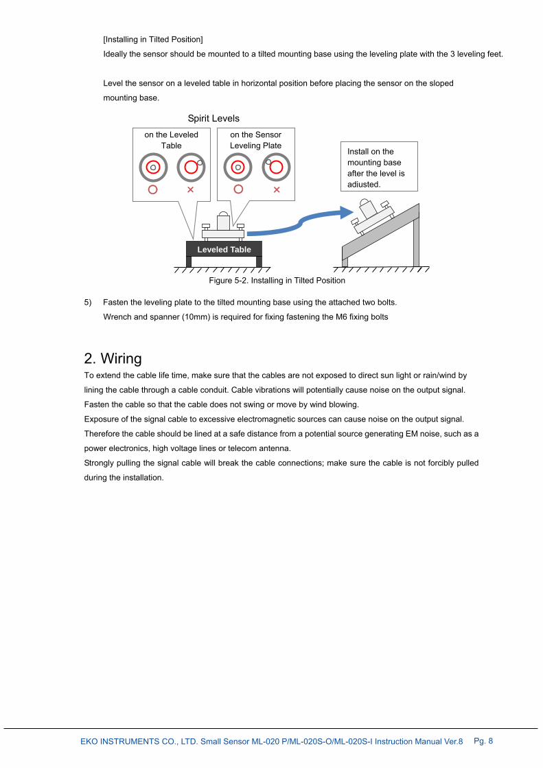
[Installing in Tilted Position]
Ideally the sensor should be mounted to a tilted mounting base using the leveling plate with the 3 leveling feet.
Level the sensor on a leveled table in horizontal position before placing the sensor on the sloped
mounting base.
5) Fasten the leveling plate to the tilted mounting base using the attached two bolts.
Wrench and spanner (10mm) is required for fixing fastening the M6 fixing bolts
2. Wiring To extend the cable life time, make sure that the cables are not exposed to direct sun light or rain/wind by
lining the cable through a cable conduit. Cable vibrations will potentially cause noise on the output signal.
Fasten the cable so that the cable does not swing or move by wind blowing.
Exposure of the signal cable to excessive electromagnetic sources can cause noise on the output signal.
Therefore the cable should be lined at a safe distance from a potential source generating EM noise, such as a
power electronics, high voltage lines or telecom antenna.
Strongly pulling the signal cable will break the cable connections; make sure the cable is not forcibly pulled
during the installation.
on the Sensor Leveling Plate
×
on the Leveled Table
×
Leveled Table
Install on the mounting base after the level is adjusted.
Figure 5-2. Installing in Tilted Position
Spirit Levels

EKO INSTRUMENTS CO., LTD. Small Sensor ML-020 P/ML-020S-O/ML-020S-I Instruction Manual Ver.8 Pg. 9
5-3. Cable Connect ion
1. Connecting to Measuring Device
1) Connect the ML-020 signal cable ends to a measurement device or data logger. Polarities are as
follow:
2) Check the output voltage. If some noise is seen on the output voltage, connect the shield cable and
minus (-) input terminal together.
3) Make sure to connect the cable with correct polarities to the measuring device input terminals. White wire
with red terminal is (+), orange wire with blue terminal is (-). (It is recommended to use a measurement
device with minimum 100kΩ input impedance).
2. Notes for Handling Cables The sensor signal cable comes with standard length of 5m (directly connected to ML-020 body). In case the
cable length is insufficient for your application, please request for desired length at the time of ordering. In
case you want to extend the cable length use a shielded low noise cable.
(If approximately 10~20m cable is extended, use 0.5mm2 x 2 pins shield cable).
Figure 5-3. Signal cable Ends Polarity
White Wire (+) Plus Output
Orange Wire (-) Minus Output
Shield Cable

EKO INSTRUMENTS CO., LTD. Small Sensor ML-020 P/ML-020S-O/ML-020S-I Instruction Manual Ver.8 Pg. 10
5-5. Measurement
1. Calculation To obtain each physical value from the output of the sensor, calculate the following equation
Q : Physical value [Lx, μmol・s-1・m-2]
E : Output voltage from the sensor [μV(mV)]
K : Sensitivity[μV/Lx, μV/μmol・s-1・m-2]
* The sensitivity of each sensor is indicated in the certificate.
2. Measuring Device Setting A Si sensor is integrated in the Small Sensor ML-020 Series, and it generates current corresponding to the
light intensity. Because this current is very small as only a few μA~mA, it is converted into voltage output by
load resistance. Therefore, if the sensor is connected to a measuring device with low input impedance, the
current generated by the Si sensor would flow into the measuring device causing inaccurate measurement.
It is recommended to use measuring device with input impedance more than 100kΩ for connecting with these
sensors.
If measurement range can be setup on the measuring device, select
a measurement range which can take accurate measurement
(ML-020S-O & ML-020S-I: 0~30mV, ML-020P: 0-20mV).
E
K Q=
+
- Output
Shunt Resistance
Si Sensor
Diffuser
Filter
Output
Figure 5-4. ML-020 Construction

EKO INSTRUMENTS CO., LTD. Small Sensor ML-020 P/ML-020S-O/ML-020S-I Instruction Manual Ver.8 Pg. 11
6. Maintenance & Troubleshooting
6-1. Maintenance
EKO sensors will provide accurate measurement results if the diffuser and the condition of the instrument are
maintained properly. Furthermore, regular maintenance and scheduled re-calibrations can extend the lifetime
and precision. However, environmental conditions, such as for instruments mounted near highly frequented
traffic lanes or airports, chemical industry, may have a deteriorating effect on the materials. Therefore, proper
maintenance is needed and has to be adapted to the local environmental conditions.
The following table describes the common maintenance tasks that should be performed on a regular basis:
Table 6-1. Maintenance Items
Items Maintenance Item Frequency How To Effect
Clean Glass Dome Few times in a
week (at least
once per week)
Keep the diffuser clean by
wiping it with a soft cloth. If the diffuser gets soiled (by
accumulation of dirt) the
detector output will be affected
due to a change in
transmittance. This dirt can
either be removed manually
(not using alcohol) or it is
washed off by rain
(self-cleaning effect). Check
Glass Dome condition
Weekly Check for crack and scratches
on the glass dome and the rim.
May lead to water leakage due
to rain/dew which cases
damage of the detector inside
the sensor
Check
Spirit Level Bubble
Weekly Verify if the pyranometer is
leveled by checking the bubble
is in the center ring of spirit
level. (When the pyranometer is
setup in horizontal position)
If a pyranometer in the
horizontal measurement
position is not leveled correctly
an additional cosine/azimuth
error will be introduced.
Check
Cable Condition
Weekly Verify if the cable is properly
connected, and how cable is
lined; make sure the cable is
not swinging by wind.
A disconnected cable will cause
sporadic reading errors or
failure of operation. If the cable
is damaged, it may lead to
noise or electric shock
(ventilator AC power cable).
Check
Setup Base Condition
Weekly Check if the instrument is
tightened properly to the
mounting base plate and the
base plate and/or table is
securely fastened in a proper
condition.
Loose instruments and/or
mounting plates can lead to
damages of the instruments
and/or injury.

EKO INSTRUMENTS CO., LTD. Small Sensor ML-020 P/ML-020S-O/ML-020S-I Instruction Manual Ver.8 Pg. 12
6-2. Cal ibrat ion Method
It is recommended to recalibrate the instrument once every 2 years. For further information about the
calibration and recalibration of your solar sensors, please contact EKO.
[Indoor Calibration Procedure]
The ML-020 reference sensor is calibrated indoor using 1000W/m2 AAA class solar simulator. The
sensitivity figure of the production ML-020 is determined by calculating the output ratio multiplied by the
sensitivity figure of the reference model.
Traceability
ML-020S-I/S-O:
The ML-020S reference sensor equipment measures sunlight and calibrates outdoors at the same time as
the reference of illuminometer.
The reference of illuminometer is calibrated using a standard lump traceable to JEMIC (Japan Electric Meters
Inspection Corporation).
ML-020P:
The ML-020P reference sensor equipment measures sunlight and calibrates outdoors at the same time as
the reference of spectroradiometer.
The reference of spectroradiometer is calibrated using a standard limp traceable to NIST.
The data logger system used in the calibration measurement is traceable to JEMIC.
See Appendix A-2 for traceability diagram.
6-3. Troubleshoot ing
Check the following items in case of trouble with the instrument. If any questions should remain, contact EKO
for further technical support.
Table 6-2. Troubleshooting
Failure Action
There is no output
Make sure that the sensor cable is connected properly to the measurement
device. To verify the sensor connection, measure the impedance of signal cable
(between the “+” and the “-” wires) and check if the measured impedance is within
the proper range as shown on the specification.
Check whether the measurement range setup on the measuring device is
appropriate.
Output value is too
low The diffuser maybe covered by rain drops or got soiled. Clean the diffuser with a
soft cloth.

EKO INSTRUMENTS CO., LTD. Small Sensor ML-020 P/ML-020S-O/ML-020S-I Instruction Manual Ver.8 Pg. 13
7. Specification
7-1. Main Unit
The spectral response for ML-020 is shown in graph in the Appendix A-1 section.
Table 7-1. Main Unit Specification
ML-020P ML-020S-O ML-020S-I
Product Name Photon Meter Outdoor Luxmeter Indoor Luxmeter
Measurement Range 0~3000
μmol・s-1・m-2 0~150,000
Lx 0~30,000
Lx
Output (Approx.) 0~20,000µV (0~20mV)
0~30,000μV (0~30mV)
Internal Resistance (Approx.) 30Ω 280Ω 1.3kΩ
Operating Temperature -10~+50
Temperature Response
(-10~+50) (Approx.) 1%
Size
Sensor Only φ22 x 33mm
With Mounting
Plate φ80 x 51mm
Weight
Sensor Only 65g
With Mounting
Plate 475g
7-2. Cables
Table 7-2 Cable Specifications
Cables Details Terminal Wire Output
Signal cable
Diameter:
Cable end:
0.18mm2 x 2pins
φ3.2mm
pin terminal
Red
Blue
White
Orange
(+) Plus
(-) Minus
Figure 7-1. Signal cable
White Wire (+) Plus Output
Orange Wire (-) Minus Output Shield Cable

EKO INSTRUMENTS CO., LTD. Small Sensor ML-020 P/ML-020S-O/ML-020S-I Instruction Manual Ver.8 Pg. 14
7-3. Dimensions
1. ML-020 Dimension (without Leveling Plate)
2. ML-020 Dimension (with optional Leveling Plate)
Figure 7-3. Outer Dimensions of Sensor and Leveling Plate
Figure 7-2. Outer Dimensions of Sensor

EKO INSTRUMENTS CO., LTD. Small Sensor ML-020 P/ML-020S-O/ML-020S-I Instruction Manual Ver.8 Pg. 15
7-4. Accessor ies List
Table 7-3. Accessories List
Option Items Remarks
Leveling Plate
Sensor Mounting Screws (M2x6mm, 3pcs & extra 3pcs for spare)
Leveling Screws(Bolts: M5x20mm, 3pcs)
Fixing bolts (Bolts: M6x50mm, 2pcs, Washers: M6, 4pcs, Nuts: M6, 2pcs)
Cable length 5m (Optional 10m, 30m, 50m)

EKO INSTRUMENTS CO., LTD. Small Sensor ML-020 P/ML-020S-O/ML-020S-I Instruction Manual Ver.8 Pg. 16
APPENDIX
A-1. Spectral & Direct ional Response Character ist ics
Below are the typical values of the spectral response and directional response.

EKO INSTRUMENTS CO., LTD. Small Sensor ML-020 P/ML-020S-O/ML-020S-I Instruction Manual Ver.8 Pg. 17
A-2. Traceabi l i ty
[ ML-020S-I, ML-020S-O ]
*National Institute of Advanced Industrial Science and Technology
**Japan Electric Meters Inspection Corporation
Lux Standard Electric Standard
JEMIC**
International Standard
National Standard
Calibration Laboratory
Reference Instrument
EKO Reference Sensors
Digital Multi-meter
(34401A)
Small Sensor Product
AIST*
Luxmeter
(by Topcon)
Digital Multi-meter
Small Sensor
(ML-020S)
JEMIC**
AIST*
Standard Lamp

EKO INSTRUMENTS CO., LTD. Small Sensor ML-020 P/ML-020S-O/ML-020S-I Instruction Manual Ver.8 Pg. 18
[ ML-020P ]
*National Institute of Advanced Industrial Science and Technology
**Japan Electric Meters Inspection Corporation
Calibration Laboratory
Reference Instrument
Small Sensor
Spectral Standard
Standard Lamp
(NIST)
Standard Lamp
(OL-FEL Reference)
Standard Lamp
(OL-FEL)
Precision Spectroradiometer
(MS-711)
Small Sensor
(ML-020P)
International Standard
National Standard
EKO Reference Sensors
Product
Electric Standard
JEMIC**
Digital Multi-meter
(34401A)
AIST*
Digital Multi-meter

EKO Asia, Oceania
1-21-8 Hatagaya,
Shibuya-ku, Tokyo
151-0072 Japan
P. +81.3.3469.6711
F. +81.3.3469.6719
www.eko.co.jp
EKO North America
111 North Market Street,
Suite 300, San Jose,
CA 95113, USA
P. +1-408-977-7751
F. +1-408-977-7741
www.eko-usa.com
EKO Europe,
Middle East, Africa,
South America
Lulofsstraat 55, Unit 28,
2521 AL, Den Haag,
The Netherlands
P. +31 (0)70 3050117
F. +31 (0)70 3840607
www.eko-eu.com