small scale multi path measurements
TRANSCRIPT

SUBJECT CODE & NAME: EC6801-WIRELESS COMMUNICATION
Presented ByS.SIVAGANESAN
Assistant Professor of ECEKIT-Kalaignar Karunanidhi Institute of Technology
Coimbatore
SMALL SCALE MULTİPATH MEASUREMENTS
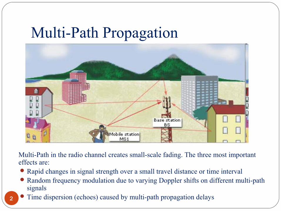
Multi-Path Propagation
2
Multi-Path in the radio channel creates small-scale fading. The three most important effects are: Rapid changes in signal strength over a small travel distance or time interval Random frequency modulation due to varying Doppler shifts on different multi-path
signals Time dispersion (echoes) caused by multi-path propagation delays
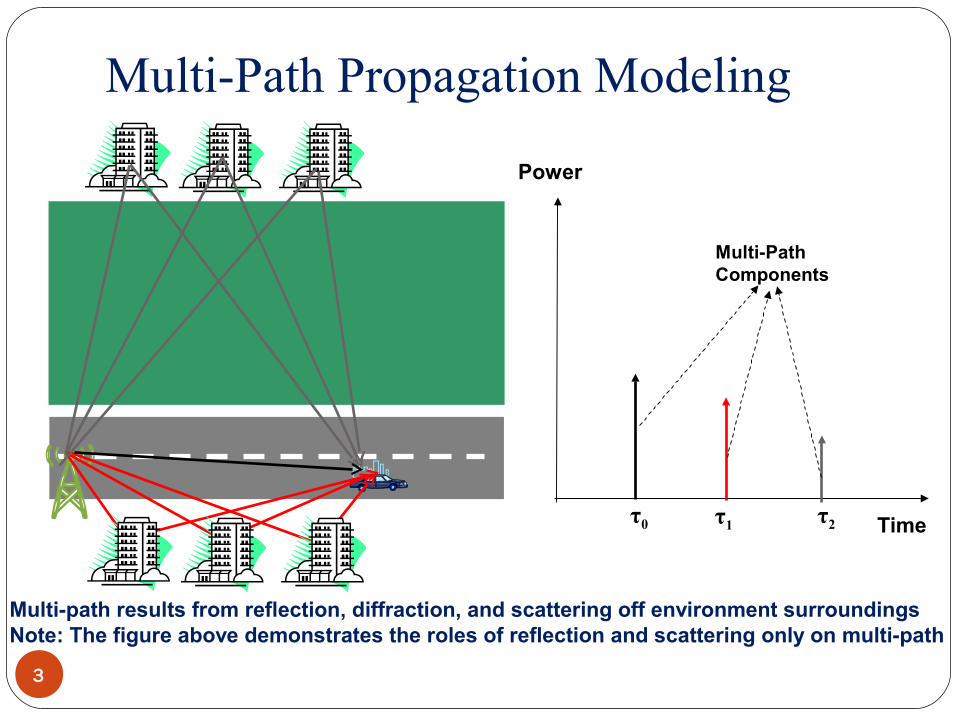
Multi-Path Propagation Modeling
3
Multi-path results from reflection, diffraction, and scattering off environment surroundingsNote: The figure above demonstrates the roles of reflection and scattering only on multi-path
Power
Timeτ0 τ1 τ2
Multi-Path Components

Multi-Path Propagation Modeling
4
Power
Timeτ0 τ1 τ2
Multi-Path Components
As the mobile receiver (i.e. car) moves in the environment, the strength of each multi-path component varies

Types of Small-Scale Fading
5

Small-Scale Multipath Measurements
6
Multipath structure is very important for small scale fading.
Several MethodsDirect RF Pulse SystemSpread Spectrum Sliding Correlator Channel SoundingFrequency Domain Channel Sounding
These techniques are also called channel sounding techniques

Direct RF Pulse System
7
This method help us to determine the power delay profile directly
Objective is to find impulse responseA narrow pulse is used for channel sounding.At the receiver the signal is amplified and detected using an
envelop detector.It is then stored on a high speed digital oscilloscope.If the receiver is set on averaging mode, the local average power
delay profile is obtained

Direct RF Pulse System
8
Pulse Generator
BPF DetectorDigital
Oscilloscope
RF Link
fc
Tx
Rx

Direct RF Pulse System
9
Problems:Subject to interferenceSubject to noise due to wideband pass band filter required for
multipath resolutionThe phases of individual multi path components are not received
due to the use of envelop detector
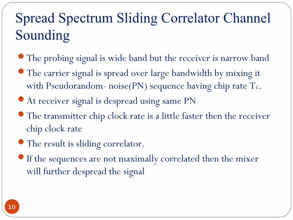
Spread Spectrum Sliding Correlator Channel Sounding
10
The probing signal is wide band but the receiver is narrow bandThe carrier signal is spread over large bandwidth by mixing it
with Pseudorandom- noise(PN) sequence having chip rate Tc.At receiver signal is despread using same PNThe transmitter chip clock rate is a little faster then the receiver
chip clock rateThe result is sliding correlator.If the sequences are not maximally correlated then the mixer
will further despread the signal
Spread Spectrum Sliding Correlator Channel Sounding
11
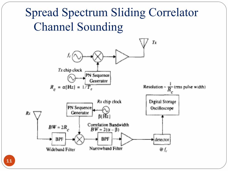
Spread Spectrum Sliding Correlator Channel Sounding
12
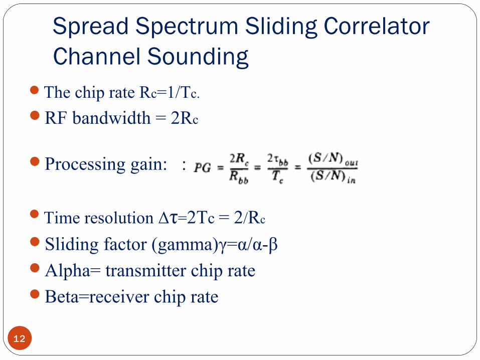
The chip rate Rc=1/Tc.
RF bandwidth = 2Rc
Processing gain: :
Time resolution Δτ=2Tc = 2/Rc
Sliding factor (gamma)γ=α/α-βAlpha= transmitter chip rateBeta=receiver chip rate
Spread Spectrum Sliding Correlator Channel Sounding
13
Advantages:Improves coverage range using same transmitter power.Transmitter receiver synchronization is eliminated using
sliding correlator.Disadvantages:Measurement are not made real timeThe associated time required is morePhase information is lost.

Frequency Domain Channel Sounding
14
Because of the dual relationship between time and frequency it is possible to measure channel impulse response in frequency domain
A vector network analyzer is used.The S-parameter test set is used to monitor the frequency
response of the channel.The frequency sweeper scans a particular frequency band by
stepping through the discrete frequencies.

Frequency Domain Channel Sounding
15

Frequency Domain Channel Sounding
16
The number and spacing of frequency steps impact the time resolution of impulse response measurements.
The response is converted to time domain by using Inverse Discrete time Fourier Transform(IDFT)

Frequency Domain Channel Sounding
17
Disadvantages:System requires careful calibrationSystem required hardwired synchronization between
transmitter and receiver.Practical only for indoor channel measurementsNon real time nature of measurementsFor time varying channels the channel impulse response may
change giving erroneous measurements

THANK YOU