sm335_e
TRANSCRIPT

System Solutions
SM 335 – High–Speed Analog Input/OutputModule for the SIMATIC S7–300
Manual Edition 01.99


6ES7 335–7HG00–8BA1
Edition 01.99
Introduction, Contents
Characteristics and TechnicalSpecifications of the SM 335 1
Conncecting the Inputs and Out-puts of the SM 335 2
Data Exchange with the SM 335 3
Interval Counter Input 4
Special SM 335 Operating Modes 5
Detecting and Correcting Faults 6
Program Examples for theSM�335 7
Index A
SIMATIC S7
SM 335 – High–Speed AnalogInput/Output Module for the S7–300
Manual

SIMATIC documentation
Edition coding
Brief details of this edition and previous editions are listed below
The status of each edition is shown by the code in the ”Remarks” column.
Status code in the ”Remarks” column:
A New documentation.. . . . B Unrevised reprint with new Order No.. . . . C Revised edition with new status . . . .
If factual changes have been made on the page since the last edition, this is indicated by a new edition coding in the header on that page.
Edition Order No. Remarks
03.97 6ES7 335–7HG00–8BA0 A
01.99 6ES7 335–7HG00–8BA1 C
For more information, refer to the Internet:http://www.ad.siemens.de/simatic
This publication was produced on Interleaf V 5.4
The reproduction, transmission or use of this document or itscontents is not permitted without express written authority. Offenderswill be liable for damages. All rights, including rights created by patentgrant or registration of a utility model or design, are reserved.
Siemens AG 1997, 1999. All rights reserved.
Functions may be executable in the control but are not described inthis documentation. No claims can be made on these functions ifincluded with a new shipment or when involved with service.
We have checked the contents of this document to ensure that theycoincide with the described hardware and software. The informationin this document is regularly checked and necessary corrections areincluded in reprints. We are thankful for any recommendations forimprovement.
Subject to change without prior notice.
Siemens–AktiengesellschaftOrder No. 6ES7 335–7HG00–8BA1Printed in the Federal Republic of Germany
3ls

This manual contains notices intended to ensure personal safety, as well as to protectthe products and connected equipment against damage. These notices are highlightedby the symbols shown below and graded according to severity by the following texts:
!Danger
indicates that death, severe personal injury or substantial property damage will resultif proper precautions are not taken.
!Warning
indicates that death, severe personal injury, or substantial property damage can resultif proper precautions are not taken.
!Caution
indicates that minor personal injury or property damage can result if proper precau-tions are not taken.
Note
contains important information about the product, its operation or a part of the docu-ment to which special attention is drawn.
A device/system may only be commissioned or operated by qualified personnel .Qualified personnel as referred to in the safety guidelines in this document are personsauthorized to energize, de-energize, clear, ground, and tag circuits, equipment andsystems in accordance with established safety practice.
For a detailed description of the safety-related guidelines, please refer to the Appendix.
Please observe the following:
!Warning
The equipment/system or the system components may only be used for the applica-tions described in the catalog or the technical description, and only in combination withthe equipment, components, and devices of other manufacturers as far as this is re-commended or permitted by Siemens.
The product will function correctly and safely only if it is transported, stored, set up,and installed as intended, and operated and maintained with care.
SIMATIC� and SINEC� are registered trade marks of SIEMENS AG.
Safety-related Guidelines
Qualified Personnel
Proper Usage
Registered Trade-marks
vii Siemens AG 1997, 1999 All Rights reserved 6ES7 335–7HG00 SM 335 – High–Speed Analog Input/Output Module for the S7–300
Introduction
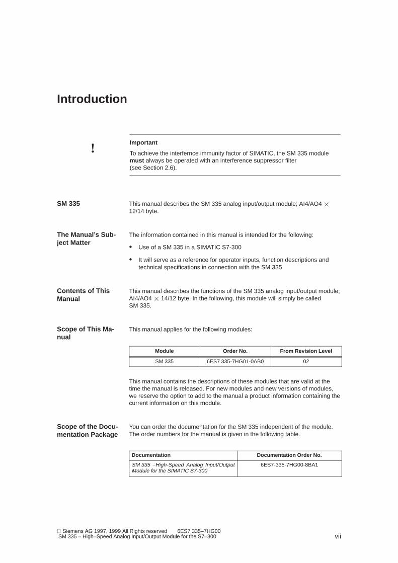
!Important
To achieve the interfernce immunity factor of SIMATIC, the SM 335 modulemust always be operated with an interference suppressor filter (see Section 2.6).
This manual describes the SM 335 analog input/output module; AI4/AO4 �12/14 byte.
The information contained in this manual is intended for the following:
� Use of a SM 335 in a SIMATIC S7-300
� It will serve as a reference for operator inputs, function descriptions andtechnical specifications in connection with the SM 335
This manual describes the functions of the SM 335 analog input/output module;AI4/AO4 � 14/12 byte. In the following, this module will simply be calledSM 335.
This manual applies for the following modules:
Module Order No. From Revision Level
SM 335 6ES7 335-7HG01-0AB0 02
This manual contains the descriptions of these modules that are valid at thetime the manual is released. For new modules and new versions of modules,we reserve the option to add to the manual a product information containing thecurrent information on this module.
You can order the documentation for the SM 335 independent of the module.The order numbers for the manual is given in the following table.
Documentation Documentation Order No.
SM 335 –High-Speed Analog Input/OutputModule for the SIMATIC S7-300
6ES7-335-7HG00-8BA1
SM 335
The Manual’s Sub-ject Matter
Contents of ThisManual
Scope of This Ma-nual
Scope of the Docu-mentation Package
01.99
viii Siemens AG 1997, 1999 All Rights reserved 6ES7 335–7HG00
SM 335 – High–Speed Analog Input/Output Module for the S7–300
The S7-300 Programmable Controller – Hardware and Installation Manual inclu-des a list with reference literature on the S7–300 and programmable controllersin general.
This manual features the following overviews for fast reference to specific infor-mation:
� The manual starts with a complete table of contents in the manual.
� In the various chapters, the headlines on the left margin highlight the con-tents of the particular section.
� The index at the end of this manual enables you to get fast access to theinformation required.
The S7-300 programmable controller complies with the IEC 1131.
If you have any queries about the S7-300 programmable controller, please con-tact your local Siemens representative.
A list of Siemens representatives worldwide is contained in the S7-300 Pro-grammable Controller – Hardware and Installation.
In case you have any questions or suggestions concerning this manual, pleasefill in the correction sheet at the end of the manual and return it to us.
Other References
Structure of thisManual
Standards
Queries
Introduction
ix Siemens AG 1997, 1999 All Rights reserved 6ES7 335–7HG00 SM 335 – High–Speed Analog Input/Output Module for the S7–300
Contents
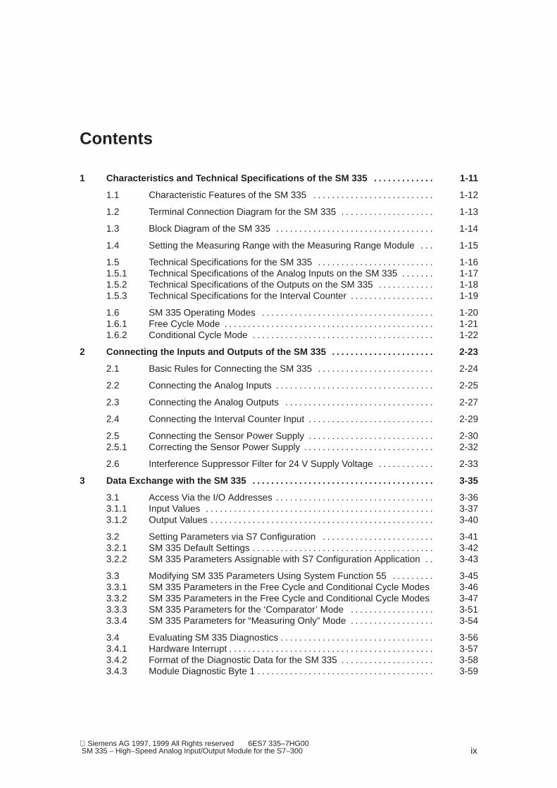
1 Characteristics and Technical Specifications of the SM 335 1-11. . . . . . . . . . . . .
1.1 Characteristic Features of the SM 335 1-12. . . . . . . . . . . . . . . . . . . . . . . . . .
1.2 Terminal Connection Diagram for the SM 335 1-13. . . . . . . . . . . . . . . . . . . .
1.3 Block Diagram of the SM 335 1-14. . . . . . . . . . . . . . . . . . . . . . . . . . . . . . . . . .
1.4 Setting the Measuring Range with the Measuring Range Module 1-15. . .
1.5 Technical Specifications for the SM 335 1-16. . . . . . . . . . . . . . . . . . . . . . . . . 1.5.1 Technical Specifications of the Analog Inputs on the SM 335 1-17. . . . . . . 1.5.2 Technical Specifications of the Outputs on the SM 335 1-18. . . . . . . . . . . . 1.5.3 Technical Specifications for the Interval Counter 1-19. . . . . . . . . . . . . . . . . .
1.6 SM 335 Operating Modes 1-20. . . . . . . . . . . . . . . . . . . . . . . . . . . . . . . . . . . . . 1.6.1 Free Cycle Mode 1-21. . . . . . . . . . . . . . . . . . . . . . . . . . . . . . . . . . . . . . . . . . . . . 1.6.2 Conditional Cycle Mode 1-22. . . . . . . . . . . . . . . . . . . . . . . . . . . . . . . . . . . . . . .
2 Connecting the Inputs and Outputs of the SM 335 2-23. . . . . . . . . . . . . . . . . . . . . .
2.1 Basic Rules for Connecting the SM 335 2-24. . . . . . . . . . . . . . . . . . . . . . . . .
2.2 Connecting the Analog Inputs 2-25. . . . . . . . . . . . . . . . . . . . . . . . . . . . . . . . . .
2.3 Connecting the Analog Outputs 2-27. . . . . . . . . . . . . . . . . . . . . . . . . . . . . . . .
2.4 Connecting the Interval Counter Input 2-29. . . . . . . . . . . . . . . . . . . . . . . . . . .
2.5 Connecting the Sensor Power Supply 2-30. . . . . . . . . . . . . . . . . . . . . . . . . . . 2.5.1 Correcting the Sensor Power Supply 2-32. . . . . . . . . . . . . . . . . . . . . . . . . . . .
2.6 Interference Suppressor Filter for 24 V Supply Voltage 2-33. . . . . . . . . . . .
3 Data Exchange with the SM 335 3-35. . . . . . . . . . . . . . . . . . . . . . . . . . . . . . . . . . . . . . .
3.1 Access Via the I/O Addresses 3-36. . . . . . . . . . . . . . . . . . . . . . . . . . . . . . . . . . 3.1.1 Input Values 3-37. . . . . . . . . . . . . . . . . . . . . . . . . . . . . . . . . . . . . . . . . . . . . . . . . 3.1.2 Output Values 3-40. . . . . . . . . . . . . . . . . . . . . . . . . . . . . . . . . . . . . . . . . . . . . . . .
3.2 Setting Parameters via S7 Configuration 3-41. . . . . . . . . . . . . . . . . . . . . . . . 3.2.1 SM 335 Default Settings 3-42. . . . . . . . . . . . . . . . . . . . . . . . . . . . . . . . . . . . . . . 3.2.2 SM 335 Parameters Assignable with S7 Configuration Application 3-43. .
3.3 Modifying SM 335 Parameters Using System Function 55 3-45. . . . . . . . . 3.3.1 SM 335 Parameters in the Free Cycle and Conditional Cycle Modes 3-463.3.2 SM 335 Parameters in the Free Cycle and Conditional Cycle Modes 3-473.3.3 SM 335 Parameters for the ‘Comparator’ Mode 3-51. . . . . . . . . . . . . . . . . . 3.3.4 SM 335 Parameters for “Measuring Only” Mode 3-54. . . . . . . . . . . . . . . . . .
3.4 Evaluating SM 335 Diagnostics 3-56. . . . . . . . . . . . . . . . . . . . . . . . . . . . . . . . . 3.4.1 Hardware Interrupt 3-57. . . . . . . . . . . . . . . . . . . . . . . . . . . . . . . . . . . . . . . . . . . . 3.4.2 Format of the Diagnostic Data for the SM 335 3-58. . . . . . . . . . . . . . . . . . . . 3.4.3 Module Diagnostic Byte 1 3-59. . . . . . . . . . . . . . . . . . . . . . . . . . . . . . . . . . . . . .

01.99
x Siemens AG 1997, 1999 All Rights reserved 6ES7 335–7HG00
SM 335 – High–Speed Analog Input/Output Module for the S7–300
3.4.4 Module Diagnostic Byte 2 3-61. . . . . . . . . . . . . . . . . . . . . . . . . . . . . . . . . . . . . . 3.4.5 Module Diagnostic Byte 3 3-62. . . . . . . . . . . . . . . . . . . . . . . . . . . . . . . . . . . . . . 3.4.6 Module Diagnostic Byte 4 3-63. . . . . . . . . . . . . . . . . . . . . . . . . . . . . . . . . . . . . . 3.4.7 Channel-Specific Diagnostic Bytes 3-64. . . . . . . . . . . . . . . . . . . . . . . . . . . . . .
4 Interval Counter Input 4-67. . . . . . . . . . . . . . . . . . . . . . . . . . . . . . . . . . . . . . . . . . . . . . . .
4.1 Interval Counter Input 4-68. . . . . . . . . . . . . . . . . . . . . . . . . . . . . . . . . . . . . . . . .
4.2 Principles of Measuring with the Interval Counter 4-69. . . . . . . . . . . . . . . . .
4.3 Wiring the Interval Counter Input 4-70. . . . . . . . . . . . . . . . . . . . . . . . . . . . . . .
4.4 Initializing the SM 335’s Interval Counter 4-72. . . . . . . . . . . . . . . . . . . . . . . .
4.5 Interval Counter Values 4-73. . . . . . . . . . . . . . . . . . . . . . . . . . . . . . . . . . . . . . .
4.6 Example for Determining the Speed by Means of the Interval Counter 4-74
5 Special SM 335 Operating Modes 5-75. . . . . . . . . . . . . . . . . . . . . . . . . . . . . . . . . . . . . .
5.1 Switching to the Special Operating Modes 5-76. . . . . . . . . . . . . . . . . . . . . . .
5.2 “Comparator” Mode 5-77. . . . . . . . . . . . . . . . . . . . . . . . . . . . . . . . . . . . . . . . . . . 5.2.1 How the Comparator Mode Works 5-78. . . . . . . . . . . . . . . . . . . . . . . . . . . . . . 5.2.2 SM 335 Parameters for Comparator Mode 5-82. . . . . . . . . . . . . . . . . . . . . . . 5.2.3 Example for Switching to the “Comparator” Mode 5-85. . . . . . . . . . . . . . . . .
5.3 ‘Measuring Only’ Mode 5-86. . . . . . . . . . . . . . . . . . . . . . . . . . . . . . . . . . . . . . . . 5.3.1 Switching to “Measuring Only” Mode 5-87. . . . . . . . . . . . . . . . . . . . . . . . . . . . 5.3.2 Example for Switching to “Measuring Only” Mode 5-89. . . . . . . . . . . . . . . . .
6 Detecting and Correcting Faults 6-91. . . . . . . . . . . . . . . . . . . . . . . . . . . . . . . . . . . . . . .
6.1 Principle of Diagnostics 6-92. . . . . . . . . . . . . . . . . . . . . . . . . . . . . . . . . . . . . . .
6.2 Enabling Diagnostics with S7 Configuration 6-93. . . . . . . . . . . . . . . . . . . . . .
6.3 Evaluating the Diagnostic Data in OB 82 6-95. . . . . . . . . . . . . . . . . . . . . . . .
6.4 SM 335 Error Tree 6-97. . . . . . . . . . . . . . . . . . . . . . . . . . . . . . . . . . . . . . . . . . . .
6.5 Troubleshooting 6-98. . . . . . . . . . . . . . . . . . . . . . . . . . . . . . . . . . . . . . . . . . . . . .
7 Program Examples for the SM 335 7-101. . . . . . . . . . . . . . . . . . . . . . . . . . . . . . . . . . . . .
7.1 An Example of Reparameterizing the SM 335 7-102. . . . . . . . . . . . . . . . . . . .
A Index A-105. . . . . . . . . . . . . . . . . . . . . . . . . . . . . . . . . . . . . . . . . . . . . . . . . . . . . . . . . . . . . . . .
Contents

1-11 Siemens AG 1997, 1999 All Rights reserved 6ES7 335–7HG00 SM 335 – High–Speed Analog Input/Output Module for the S7–300
Characteristics and Technical Specifica-tions of the SM 335
The SM 335 is an input/output module (signal module) for the SIMATIC S7-300.The SM 335 has the same general technical specifications as all signal modu-les of the S7-300.
You order the SM 335 under the following order number 6ES7 335-7HG01-0AB0.
We deal with the following topics in this chapter:
Topic Section
Characteristics of the SM 335 1.1
Terminal connection diagram of the SM 335 1.2
Block diagram of the SM 335 1.3
Setting the measuring range with the measuring range module 1.4
Technical specifications of the SM 335 1.5
Operating modes of the SM 335 1.6
S7-300
Order Number
In this Chapter
1
01.99
1-12 Siemens AG 1997, 1999 All Rights reserved 6ES7 335–7HG00
SM 335 – High–Speed Analog Input/Output Module for the S7–300
1.1 Characteristic Features of the SM 335
The SM 335 AI4/AO4�14/12 bit has the following characteristic features:
� Four galvanically isolated analog inputs
� Integrated 10 V / 25 mA sensor power supply
� Measured-value resolution:
– Bipolar: 13 bits + sign
– Unipolar: 14 bits
� Selectable measured value:
– Two voltage inputs
– Two inputs which can be used as either current or voltage inputs
� Selectable measuring range for each input
� Four galvanically isolated analog outputs
� Selectable range for each analog output
For the analog outputs, you can connect loads over a two-wire connectiononly!
� Analog value resolution
– Bibolar: 11 bits + sign
– Unipolar: 12 bits
� 2 standard operating modes
– Free cycle
– Conditional cycle
� 2 special operating modes
– Comparator
– Measuring Only
� Programmable diagnostics
� Programmable diagnostic interrupt
� Programmable end-of-cycle interrupt (generates a hardware interrupt on theCPU)
Characteristic Fea-tures
1 Characteristics and Technical Spezifications of the SM 335

01.99
1-13 Siemens AG 1997, 1999 All Rights reserved 6ES7 335–7HG00 SM 335 – High–Speed Analog Input/Output Module for the S7–300
1.2 Terminal Connection Diagram for the SM 335
Figure 1-1 shows the terminal connections for the SM 335 analog input/outputmodule.
Terminal connection dia-gram
Fault LEDs – red
Analog inputs:Voltage/current measu-rement
L+
M0+
M0–
M1+M1–M2+M2–M3+M3–
M
24 V
CH 0
CH 1
CH 2
M
Analog outputsVoltage/current output
L+QV0QV1
QV3
QV2
MANA
M
24 VCH 0
CH 1
CH 2
CH 3
M
CH 3
Interval counter IZIZMIZ
QVRef
MANA 10 V
Sensor power supply
Figure 1-1 Terminal Connection Diagram for the SM 335
Please refer to Chapter 2 and to the S7-300 Programmable Controller – Hard-ware and Installation Manual for information on how to wire the inputs and out-puts on the SM 335.
Terminal Connec-tion Diagram
Wiring
1 Characteristics and Technical Spezifications of the SM 335

01.99
1-14 Siemens AG 1997, 1999 All Rights reserved 6ES7 335–7HG00
SM 335 – High–Speed Analog Input/Output Module for the S7–300
1.3 Block Diagram of the SM 335
Figure 1-2 shows the block diagram of the SM 335. You will find detailed techni-cal specifications of the SM 335 on the following pages.
A
D
CH0
CH1
CH2
CH3
CH0
CH1
CH2
CH3
10 V
Wirebreaktest circuit
A
D
24VInternal power supply
Galvanic isolation
IZ
Analog outputs
Sensor supply
Analog inputs
Interval counter input
S7-300backplane bus Logic
Figure 1-2 Block Diagram of the SM 335
As you can see from Figure 1-2, the SM 335 contains different analog parts.The analog outputs are galvanically isolated from the backplane bus of theS7-300. The outputs are on the same potential MANA. The output for sensorsupply has the same potential MANA as the analog outputs.As you can seefrom Figure
The analog inputs are galvanically isolated from each other and from the back-plane bus of the S7-300.
The input for the interval counter IZ is galvanically isolated from the other ana-log parts and from the backplane bus of the S7-300.
Block Diagram
Galvanic Isolation
1 Characteristics and Technical Spezifications of the SM 335
01.99
1-15 Siemens AG 1997, 1999 All Rights reserved 6ES7 335–7HG00 SM 335 – High–Speed Analog Input/Output Module for the S7–300
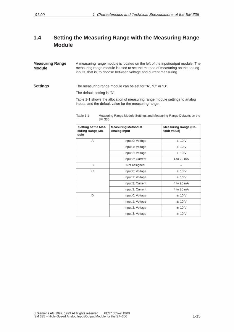
1.4 Setting the Measuring Range with the Measuring RangeModule
A measuring range module is located on the left of the input/output module. Themeasuring range module is used to set the method of measuring on the analoginputs, that is, to choose between voltage and current measuring.
The measuring range module can be set for “A”, “C” or “D”.
The default setting is “D”.
Table 1-1 shows the allocation of measuring range module settings to analoginputs, and the default value for the measuring range.
Table 1-1 Measuring Range Module Settings and Measuring-Range Defaults on theSM 335
Setting of the Mea-suring Range Mo-dule
Measuring Method at Analog Input
Measuring Range (De-fault Value)
A Input 0: Voltage � 10 V
Input 1: Voltage � 10 V
Input 2: Voltage � 10 V
Input 3: Current 4 to 20 mA
B Not assigned –
C Input 0: Voltage � 10 V
Input 1: Voltage � 10 V
Input 2: Current 4 to 20 mA
Input 3: Current 4 to 20 mA
D Input 0: Voltage � 10 V
Input 1: Voltage � 10 V
Input 2: Voltage � 10 V
Input 3: Voltage � 10 V
Measuring RangeModule
Settings
1 Characteristics and Technical Spezifications of the SM 335
01.99
1-16 Siemens AG 1997, 1999 All Rights reserved 6ES7 335–7HG00
SM 335 – High–Speed Analog Input/Output Module for the S7–300
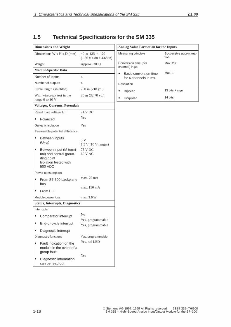
1.5 Technical Specifications for the SM 335
Dimensions and Weight
Dimensions W x H x D (mm) 40 ��125 ��120(1.56 x 4.88 x 4.68 in)
Weight Approx. 300 g
Module-Specific Data
Number of inputs 4
Number of outputs 4
Cable length (shielded) 200 m (218 yd.)
With wirebreak test in therange 0 to 10 V
30 m (32.70 yd.)
Voltages, Currents, Potentials
Rated load voltage L +
� Polarized
24 V DC
Yes
Galvanic isolation Yes
Permissible potential difference
� Between inputs(UCM)
� Between input (M termi-nal) and central groun-ding pointIsolation tested with500 VDC
3 V1.5 V (10 V ranges)
75 V DC60 V AC
Power consumption
� From S7-300 backplanebus
� From L +
max. 75 mA
max. 150 mA
Module power loss max. 3.6 W
Status, Interrupts, Diagnostics
Interrupts
� Comparator interrupt
� End-of-cycle interrupt
� Diagnostic interrupt
No
Yes, programmable
Yes, programmable
Diagnostic functions
� Fault indication on themodule in the event of agroup fault
� Diagnostic informationcan be read out
Yes, programmable
Yes, red LED
Yes
Analog Value Formation for the Inputs
Measuring principle Successive approxima-tion
Conversion time (per channel) in �s
Max. 200
� Basic conversion timefor 4 channels in ms
Max. 1
Resolution
� Bipolar 13 bits + sign
� Unipolar 14 bits
1 Characteristics and Technical Spezifications of the SM 335
01.99
1-17 Siemens AG 1997, 1999 All Rights reserved 6ES7 335–7HG00 SM 335 – High–Speed Analog Input/Output Module for the S7–300
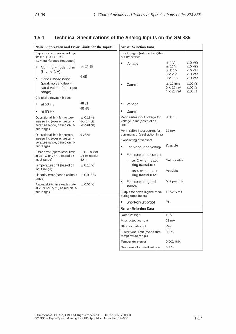
1.5.1 Technical Specifications of the Analog Inputs on the SM 335
Noise Suppression and Error Limits for the Inputs
Suppression of noise voltagefor = n � (f1�1 %), (f1 = interference frequency)
� Common-mode noise(UPP � 3 V)
� Series-mode noise(peak noise value <rated value of the inputrange)
� 65 dB
0 dB
Crosstalk between inputs
� at 50 Hz
� at 60 Hz
65 dB
65 dB
Operational limit for voltagemeasuring (over entire tem-perature range, based on in-put range)
� 0.15 %(for 14-bitresolution)
Operational limit for currentmeasuring (over entire tem-perature range, based on in-put range)
0.25 %
Basic error (operational limitat 25 �C or 77 �F, based oninput range)
� 0.1 % (for14-bit resolu-tion)
Temperature drift (based oninput range)
� 0.13 %
Linearity error (based on inputrange)
� 0.015 %
Repeatability (in steady stateat 25 °C or 77 °F, based on in-put range)
� 0.05 %
Sensor Selection Data
Input ranges (rated values)/In-put resistance
� Voltage � 1 V;� 10 V;� 2.5 V;0 to 2 V0 to 10 V
/10 M�
/10 M�
/10 M�
/10 M�
/10 M�
� Current � 10 mA;0 to 20 mA4 to 20 mA
/100 �/100 �/100 �
� Voltage
� Current
Permissible input voltage forvoltage input (destructionlimit)
�30 V
Permissible input current forcurrent input (destruction limit)
25 mA
Connecting of sensors
� For measuring voltage
� For measuring current
Possible
– as 2-wire measu-ring transducer
Not possible
– as 4-wire measu-ring transducer
Possible
� For measuring resi-stance
Not possible
Output for powering the mea-suring transducers
10 V/25 mA
� Short-circuit-proof Yes
Sensor Selection Data
Rated voltage 10 V
Max. output current 25 mA
Short-circuit-proof Yes
Operational limit (over entiretemperature range)
0.2 %
Temperature error 0.002 %/K
Basic error for rated voltage 0.1 %
1 Characteristics and Technical Spezifications of the SM 335

01.99
1-18 Siemens AG 1997, 1999 All Rights reserved 6ES7 335–7HG00
SM 335 – High–Speed Analog Input/Output Module for the S7–300
1.5.2 Technical Specifications of the Outputs on the SM 335
Analog Value Formation for the Outputs
Resolution (incl. overrange)
� � 10 V
� From 0 to 10 V
11 bits + sign
12 bits + sign
Conversion time (per channel)in �s
Max. 800
Setting time
� for resistive load � 0.1 ms
� for capacitive load � 3.3 ms
� for inductive load � 0.5 ms
Injection of substitute values Yes
Noise Suppression and Error Limits for the Outputs
Crosstalk between outputs 40 dB
Operational limit (over entiretemperature range, based onoutput range)
0.5 %
Basic error (operational limit at25°C or 77°F, based on outputrange)
0.2 %
Temperature error (based onoutput range)
0.02 %/K
Linearity error (based on outputrange)
� 0.05 %
Repeatability (in steady state at25°C or 77°F, based on outputrange)
� 0.05 %
Output ripple (based on outputrange)
� 0.05 %
Actuator Selection Data
Output range (rated values)
� 10 VFrom 0 to 10 V
Burden resistance
� for voltage outputs
� for capacitive load
� for inductive load
Min. 3 k�
Max. 1 �F
Max. 1 mH
Voltage output
� Short-circuit protection
� Short-circuit current
Yes
Max. 8 mA
Connection of actuators
� For voltage output with2-wire connection4-wire connection(measuring circuit)
PossibleNot possible
1 Characteristics and Technical Spezifications of the SM 335

01.99
1-19 Siemens AG 1997, 1999 All Rights reserved 6ES7 335–7HG00 SM 335 – High–Speed Analog Input/Output Module for the S7–300
1.5.3 Technical Specifications for the Interval Counter
The technical specifications for the interval counter’s input are listed in the tablebelow.
Data Specific to the Interval Counter
Number of inputs 1
Cable length (shielded) 200 m
Voltages, Currents, Potentials
Rated load voltage L+
� Polarized
DC 24 V
Yes
Galvanic isolation Yes
Permissible potential difference
� Interval counter input(MIZ terminal) to thefour analog inputs
� Between input MIZ ter-minal and central groun-ding point
DC 75 V/AC 60 V
DC 75 VAC 60 V
Analog Value Formation for the Interval Counter Input
Measuring principle Detection of a risingedge and measuringthe amount of time be-tween two edges
Resolution of the time differ-ence
0.5 �s
Max. frequency
� Programmable
400 HzNo
� Interference suppres-sion for interference fre-quency fl in dB
0
Noise Suppression and Error Limits for the Input
Noise suppression for F = n � (f1 � 1 %), (f1 = inter-ference frequency)
� Common-mode noise(UPP � 3 V)
� Series-mode noise(peak noise value < no-minal value of inputrange)
� 80 dB
0 dB
Operational limit (over entiretemperature range)
Max. 1 % at 400 Hz
Basic error (operational limit at25°C or 77°F)
0.005 %
Temperature error (0 to 60°C or32 to 140°F)
� 0.003 %/K
Linearity error 0
Sensor Selection Data
Permissible input voltage (de-struction limit)
� 30 V
Permissible input current for in-terval input (destruction limit)
5 mA
Minimum permissible pulsewidths at the counter input
� ”Low”
� ”High”
1 ms
1 ms
Permissible voltage range be-tween IZ and MIZ terminals
� for “Low” pulse
� for “High” pulse
– 30 V to + 5 V(– 4.4 mA to 0.7 mA)
+ 18 V to + 30 V(2.5 mA to 4.4 mA)
Technical Speci-fications
1 Characteristics and Technical Spezifications of the SM 335

01.99
1-20 Siemens AG 1997, 1999 All Rights reserved 6ES7 335–7HG00
SM 335 – High–Speed Analog Input/Output Module for the S7–300
1.6 SM 335 Operating Modes
The SM 335 can operate in the following modes:
� Free cycle
� Conditional cycle
In addition, the SM 335 can be switched to the following modes for a brief pe-riod of time:
� ‘Comparator’ mode
� ‘Measuring Only’ mode
The special operating modes are described in Chapter 5 where there is also adescription of how to switch to the special operating modes.
Operating Modes
Special OperatingModes
1 Characteristics and Technical Spezifications of the SM 335

01.99
1-21 Siemens AG 1997, 1999 All Rights reserved 6ES7 335–7HG00 SM 335 – High–Speed Analog Input/Output Module for the S7–300
1.6.1 Free Cycle Mode
In conjunction with the SM 335, the word “cycle” is used to mean the measuring,or sampling, of the analog value at all analog inputs in succession. Once themeasuring cycle is completed, it starts again from the beginning. This cycle hasnothing to do with cyclic program scanning on a SIMATIC S7 CPU.
When the SM 335 operates in Free Cycle mode, all SM 335 analog inputs andoutputs are processed successively and without interruption. After all inputs andoutputs have been processed, conversion once again begins with the first ana-log input.
Figure 1-3 shows the various components of the cycle time for a free cycle.
Conversion time for analog input 3
Cycle time
Conversion time for analog input 4
Conversion time for analog output 1
Conversion time for analog output 2
Conversion time for analog input 3
Conversion time for analog input 4
Conversion time for analog output 1
Conversion time for analog output 2
Figure 1-3 Cycle Time for the SM 335’s Free Cycle
Cycle
Free Cycle
1 Characteristics and Technical Spezifications of the SM 335

01.99
1-22 Siemens AG 1997, 1999 All Rights reserved 6ES7 335–7HG00
SM 335 – High–Speed Analog Input/Output Module for the S7–300
1.6.2 Conditional Cycle Mode
In the conditional cycle operating mode, you can define the cycle time. Follo-wing conversion of all inputs/outputs, the SM 335 generates an end-of-cycleinterrupt to the CPU. The SM 335 then waits while the analog outputs are upda-ted and begins the next processing cycle after the specified cycle time has expi-red.
Figure 1-4 shows the components of the cycle time for a conditional cycle.
Updating of theanalog outputs
Every 1 ms, 1.5 ms,..., 16 ms
optional
Time condition:Start new cycle
Yes
No
Conversion time for analog input 3
Conversion time for analog input 4
Conversion time for analog output 1
Conversion time for analog output 2
End-of-cycleinterrupt
Figure 1-4 Cycle Time for a Conditional SM 335 Cycle
�
Conditional Cycle
1 Characteristics and Technical Spezifications of the SM 335

2-23 Siemens AG 1997, 1999 All Rights reserved 6ES7 335–7HG00 SM 335 – High–Speed Analog Input/Output Module for the S7–300
Connecting the Inputs and Outputs of theSM 335
Before connecting the SM 335, you must first assemble it. You assemble theSM 335 in the same way as all other input/output modules of the SIMATICS7-300. Please refer to the S7-300 Programmable Controller – Hardware andInstallation Manual for information on this topic.
When connecting the SM 335, please note the installation guidelines in theS7-300 Programmable Controller – Hardware and Installation Manual. In thepresent manual, we describe special features that apply to the SM 335.
In this chapter, we deal with the following topics:
Topic Section
Basic information on connecting the SM 335 2.1
Connecting the analog inputs 2.2
Connecting the analog outputs 2.3
Connecting the interval counter input 2.4
Connecting the sensor supply 2.5
Interference suppressor filter for 24 V supply voltage 2.6
Assembly
S7-300
In this Chapter
2

01.99
2-24 Siemens AG 1997, 1999 All Rights reserved 6ES7 335–7HG00
SM 335 – High–Speed Analog Input/Output Module for the S7–300
2.1 Basic Rules for Connecting the SM 335
The analog inputs and outputs are switched as described in the S7-300 Pro-grammable Controller – Hardware and Installation Manual.
The following applies:
� The cables must be twisted-pair cables, protected against interference andshielded.
� The accuracy of your measurements depends on the following:
– Load
– Cable between the SM 335 and the load
– Reference voltage
The SM 335 must be supplied with 24 V DC. The 24 V must be connected to L+(PIN 1), the 24 V’s zero potential to M (PIN 20).
You can ground the 24 V power supply in the following ways:
� Direct on the 24 V power supply unit or
� On the S7 CPU (if you use the 24 V power supply on the CPU).
Connecting theAnalog Inputs andOutputs
Rules
Power Supply
Grounding
2 Connecting the Inputs and Outputs of the SM 335
01.99
2-25 Siemens AG 1997, 1999 All Rights reserved 6ES7 335–7HG00 SM 335 – High–Speed Analog Input/Output Module for the S7–300
2.2 Connecting the Analog Inputs
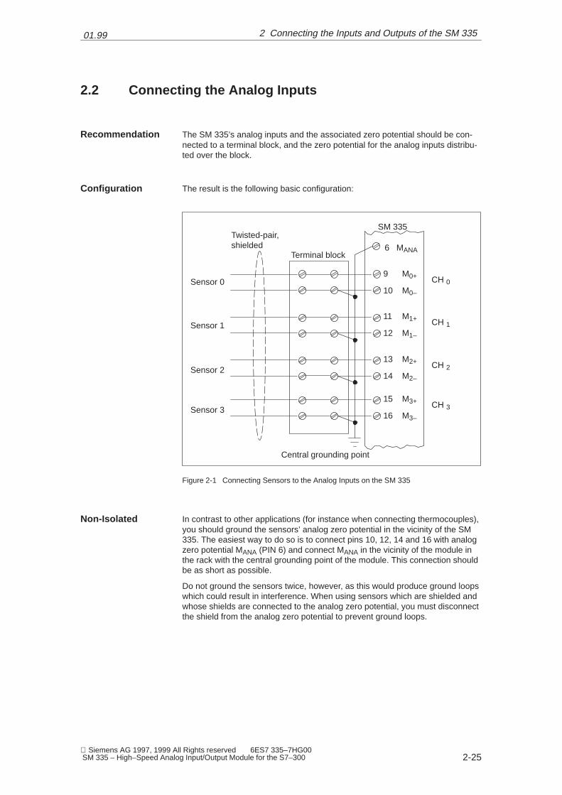
The SM 335’s analog inputs and the associated zero potential should be con-nected to a terminal block, and the zero potential for the analog inputs distribu-ted over the block.
The result is the following basic configuration:
Sensor 0
Sensor 1
Sensor 2
Sensor 3
SM 335
CH 0
CH 1
CH 2
CH 3
9 M0+
11 M1+
13 M2+
15 M3+
10 M0–
12 M1–
14 M2–
16 M3–
6 MANA
Central grounding point
Twisted-pair,shielded
Terminal block
Figure 2-1 Connecting Sensors to the Analog Inputs on the SM 335
In contrast to other applications (for instance when connecting thermocouples),you should ground the sensors’ analog zero potential in the vicinity of the SM335. The easiest way to do so is to connect pins 10, 12, 14 and 16 with analogzero potential MANA (PIN 6) and connect MANA in the vicinity of the module inthe rack with the central grounding point of the module. This connection shouldbe as short as possible.
Do not ground the sensors twice, however, as this would produce ground loopswhich could result in interference. When using sensors which are shielded andwhose shields are connected to the analog zero potential, you must disconnectthe shield from the analog zero potential to prevent ground loops.
Recommendation
Configuration
Non-Isolated
2 Connecting the Inputs and Outputs of the SM 335
01.99
2-26 Siemens AG 1997, 1999 All Rights reserved 6ES7 335–7HG00
SM 335 – High–Speed Analog Input/Output Module for the S7–300
If you use the SM 335 isolated, the maximum permissible common mode vol-tage must not be exceeded between the zero potential of the sensor and MANA,otherwise the measurement will be corrupted.
60 V AC/ 75 V DC must not be exceeded between MANA and the 24 V voltagesupply.
Unused analog inputs on the SM 335 must be short-circuited and connected toMANA. Deactivate the unused analog inputs as described in ‘S7 Configuration’.This achieves the optimum in interference immunity for the SM 335.
You can also employ unused analog inputs to monitor the sensor power supplyor analog outputs. This also enhances interference immunity.
Isolated
Unused Analog In-puts
2 Connecting the Inputs and Outputs of the SM 335

01.99
2-27 Siemens AG 1997, 1999 All Rights reserved 6ES7 335–7HG00 SM 335 – High–Speed Analog Input/Output Module for the S7–300
2.3 Connecting the Analog Outputs
Internally, the analog outputs are designed as voltage outputs. For this reason,the analog outputs must be connected as voltage outputs. For details, pleaserefer to the S7-300 Programmable Controller – Hardware and Installation Ma-nual.
If possible, the SM 335’s analog outputs, with the associated zero potential,should be connected to a terminal block from where you can tap the zero poten-tial for the analog outputs.
Connecting theAnalog Outputs
Recommendation
2 Connecting the Inputs and Outputs of the SM 335

01.99
2-28 Siemens AG 1997, 1999 All Rights reserved 6ES7 335–7HG00
SM 335 – High–Speed Analog Input/Output Module for the S7–300
This results in the following basic configuration:
SM 335
Mana 6
CH3 5
CH0 2
CH1 2
CH2 4
Twisted-pair,shielded
Actuator 0
Actuator 1
Actuator 2
Actuator 3
Figure 2-2 Connecting Actuators to the SM 335
Actuators which are shielded and whose shields are grounded and connectedto the actuator’s zero potential conductor form a ground loop. You must there-fore break the connection between shield and zero potential conductor on theactuator or use an actuator whose zero potential conductor is not connected toground.
To ensure that unused analog outputs on the SM 335 are dead, you must deac-tivate them and leave them open. An analog output is deactivated with “S7 Con-figuration” via the “Output” parameter block (see Table 3-6).
Configuration
Non-Isolated
Unused AnalogOutputs
2 Connecting the Inputs and Outputs of the SM 335

01.99
2-29 Siemens AG 1997, 1999 All Rights reserved 6ES7 335–7HG00 SM 335 – High–Speed Analog Input/Output Module for the S7–300
2.4 Connecting the Interval Counter Input
If you wire the interval counter input as non-isolated input, connect pin 19 (MIZ)and pin 20 (24 V power supply’s zero potential).
If you wire the interval counter input as isolated input, you may not connect pin19 (MIZ) to pin 20 (24 V power supply’s zero potential).
Refer to Section 4.3 for more information on connecting the interval counterinput.
Non-Isolated
Isolated
Additional Infor-mation
2 Connecting the Inputs and Outputs of the SM 335

01.99
2-30 Siemens AG 1997, 1999 All Rights reserved 6ES7 335–7HG00
SM 335 – High–Speed Analog Input/Output Module for the S7–300
2.5 Connecting the Sensor Power Supply
The sensor power supply is designed for resistance-type sensors (such as li-near potentiometers).
Figure 2-3 shows an example of how to connect the sensor power supply.
ÉÉÉÉÉÉÉÉÉÉÉÉ
10 V
0 V
URef=10V
U
SM 335
9 M0+
7 10V
10 M0–
8
6 Mana
Sensorpower supply
Measuring si-gnal
Figure 2-3 Example of How to Supply the Sensors with Power via the SM 335
Internally, the SM 335’s analog zero potential (pin 6) is connected with the 10 Vsensor power supply’s zero potential. If you use the four-wire measuring methodshown in Figure 2-3, you must not connect pin 10 to pin 6 or to zero potential.To do so would be to create a ground loop, which could cause interference.
Purpose
Connections
Non-Floating Con-figuration
2 Connecting the Inputs and Outputs of the SM 335

01.99
2-31 Siemens AG 1997, 1999 All Rights reserved 6ES7 335–7HG00 SM 335 – High–Speed Analog Input/Output Module for the S7–300
There is a voltage drop on the cable between SM 335 and the linear potentio-meter. Because of the SM 335’s high resolution, this can play a role in the mea-suring of the analog signal. You can compute the voltage drop on an electriccable as follows:
U �
r0 · I · l
A
U: Voltage drop along the cable
r0: Resistivity of the cable used (for Cu:0.0172 � mm2/m
I: Current flowing through the cable in am-peres
l: Length of the cable in meters
A: Cross-section of the cable in square milli-meters
Because of this, we would recommend keeping the cables as short as possibleand using a cable with the largest possible cross-section.
Cable
2 Connecting the Inputs and Outputs of the SM 335

01.99
2-32 Siemens AG 1997, 1999 All Rights reserved 6ES7 335–7HG00
SM 335 – High–Speed Analog Input/Output Module for the S7–300
2.5.1 Correcting the Sensor Power Supply
The power supplied for the sensors is a 10 V output voltage. This voltage maydeviate slightly from 10 V. The deviation results from the tolerances of the com-ponents used on the SM 335. Because the SM 335 has no trimming potentio-meters for re-adjusting the voltage supplied, it supplies the sensor voltage asanalog value.
The SM 335 supplies the analog value of the sensor voltage in input bytes Mo-dAdd + 10 and ModAdd + 11 (see Table 3-1 in Section 3.1.1).
The correction factor K is computed from the actual sensor voltage U and thedesired voltage.
K �
27648 (16#6C00)
U (from ModAdd� 10� ModAdd� 11)
U lies between 27620 (16#6BE4) and 27676 (16#6C1C), producing correctionfactors from 0.9989883 to 1.0010127.
The corrected analog measured value is computed as follows:
KCorr � K · UAI
KCorr = Corrected analog value
K = Correction factor
UAI = Analog value measured at the analog input
Purpose
Sensor Voltage
Correction Factor
Measured Value
2 Connecting the Inputs and Outputs of the SM 335
01.99
2-33 Siemens AG 1997, 1999 All Rights reserved 6ES7 335–7HG00 SM 335 – High–Speed Analog Input/Output Module for the S7–300
2.6 Interference Suppressor Filter for 24 V Supply Voltage
!Important
To achieve the interfernce immunity factor of SIMATIC, the SM 335 modulemust always be operated with an interference suppressor filter.
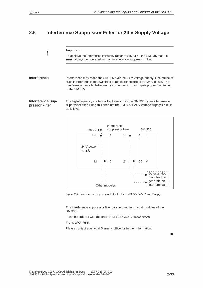
Interference may reach the SM 335 over the 24 V voltage supply. One cause ofsuch interference is the switching of loads connected to the 24 V circuit. Theinterference has a high-frequency content which can impair proper functioningof the SM 335.
The high-frequency content is kept away from the SM 335 by an interferencesuppressor filter. Bring this filter into the SM 335’s 24 V voltage supply’s circuitas follows:
SM 335
1 L+
20 M
1
2 2’
1’
M
L+
interferencesuppressor filter
Other modules
Other analogmodules thatgenerate nointerference
24 V powersupply
max. 0.1 m
Figure 2-4 Interference Suppressor Filter for the SM 335’s 24 V Power Supply
The interference suppressor filter can be used for max. 4 modules of the SM 335.
It can be ordered with the order No.: 6ES7 335–7HG00–6AA0
From: WKF Fürth
Please contact your local Siemens office for further information.
�
Interference
Interference Sup-pressor Filter
2 Connecting the Inputs and Outputs of the SM 335

01.99
2-34 Siemens AG 1997, 1999 All Rights reserved 6ES7 335–7HG00
SM 335 – High–Speed Analog Input/Output Module for the S7–300
2 Connecting the Inputs and Outputs of the SM 335

3-35 Siemens AG 1997, 1999 All Rights reserved 6ES7 335–7HG00 SM 335 – High–Speed Analog Input/Output Module for the S7–300
Data Exchange with the SM 335
Data exchange with the SM 335 is defined here as follows:
� Transfer of data to the SM 335 from the CPU and
� Reading of data from the SM 335 by the CPU.
In this section, we have summarized all the data that can be transferred to theSM 335 or supplied by the SM 335.
There are basically 4 methods of reading or writing data:
� Access via the I/O addresses (for example, with L PIW, T PQW)
� Setting parameters via S7 Configuration
� Writing parameters with the help of system function 55
� Reading diagnostics data via system function 59
Before you plug in the SM 335, you must insert the coding plug into the SM 335.The S7-300 Programmable Controller – Hardware and Installation Manual des-cribes how to insert the coding plug into the SM 335. The measuring method(current/voltage measurement) is set for the analog inputs depending on theposition in which you plug in the coding plug.
We deal with the following topics in this chapter:
Topic Section
Access via the I/O addresses 3.1
Setting parameters via S7 Configuration 3.2
Modifying SM 335 parameters with the help of system function 55 3.3
Evaluating SM 335 diagnostics 3.4
Preliminary Re-mark
Overview
Methods
Coding Plug
This Chapter
3
01.99
3-36 Siemens AG 1997, 1999 All Rights reserved 6ES7 335–7HG00
SM 335 – High–Speed Analog Input/Output Module for the S7–300
3.1 Access Via the I/O Addresses
You can access the SM 335 via I/O addresses.
Input values are values supplied by the SM 335. You can load the input valuesvia the L PIB (or L PIW or L PID) operation. The input values contain measuredvalues of the SM 335.
Output values are values you write to the SM 355 via the T PQB (or T PQW or TPQD) operation. You can transfer analog values to the SM 335 via output va-lues. The output values are output via the SM 355’s analog outputs.
Principle
Input Values
Output Values
3 Data Exchange with the SM 335

01.99
3-37 Siemens AG 1997, 1999 All Rights reserved 6ES7 335–7HG00 SM 335 – High–Speed Analog Input/Output Module for the S7–300
3.1.1 Input Values
The SM 335 converts the signals measured at the inputs into binary values.
The input values are located in bytes ModAdd (module start address) to Mo-dAdd + 15 (module start address + 15) in the process-image input table. Referto chapter entitled “Addressing” in the S7-300 Programmable Controller – Hard-ware and Installation Manual for information on how to compute the modulestart address. Table 3-1 lists the input values, their addresses, and their defaultvalues. The value shown in the ‘Default’ column is the value assumed by aninput before that input is read for the first time.
Table 3-1 SM 335 Input Values
Byte Contents Default
ModAdd + 0 High-order byte of the measuring value from measuringchannel 1
*)
ModAdd + 1 Low-order byte of the meas. value from meas. channel 1 *)
ModAdd + 2 High-order byte of the measuring value from measuringchannel 2
*)
ModAdd + 3 Low-order byte of the meas. value from meas. channel 2 *)
ModAdd + 4 High-order byte of the measuring value from measuringchannel 3
*)
ModAdd + 5 Low-order byte of the meas. value from meas. channel 3 *)
ModAdd + 6 High-order byte of the measuring value from measuringchannel 4
*)
ModAdd + 7 Low-order byte of the meas. value from meas. channel 4 *)
ModAdd + 8 For “Comparator” and ”Measuring Only” modes:
Number of suppressed end-of-cycle interrupts
Default = 1; If end-of-cycle interrupts have been suppres-sed: 1 + number of suppressed end-of-cycle interrupts
B#16#01
ModAdd + 9 ID for new comparator and return code for ”Comparatir”and ”Measuring Only”
B#16#01
ModAdd + 10 High-order byte of the sensor voltage B#16#6C*)
ModAdd + 11 Low-order byte of the sensor voltage B#16#00*)
ModAdd + 12 Interval counter B#16#00
ModAdd + 13 Interval time value in bits 16 to 24 B#16#FF
ModAdd + 14 Interval time value in bits 8 to 15 B#16#FF
ModAdd + 15 Interval time value in bits 0 to 7 B#16#FF
*) Depending on actual value
Please refer to the chapter entitled ‘Analog Modules’ in the S7-300 Programma-ble Controller – Hardware and Installation Manual for information on how ananalog value is represented in binary in the CPU and on which binary valuecorresponds to which analog value.
Principle
Format
Analog Values
3 Data Exchange with the SM 335
01.99
3-38 Siemens AG 1997, 1999 All Rights reserved 6ES7 335–7HG00
SM 335 – High–Speed Analog Input/Output Module for the S7–300
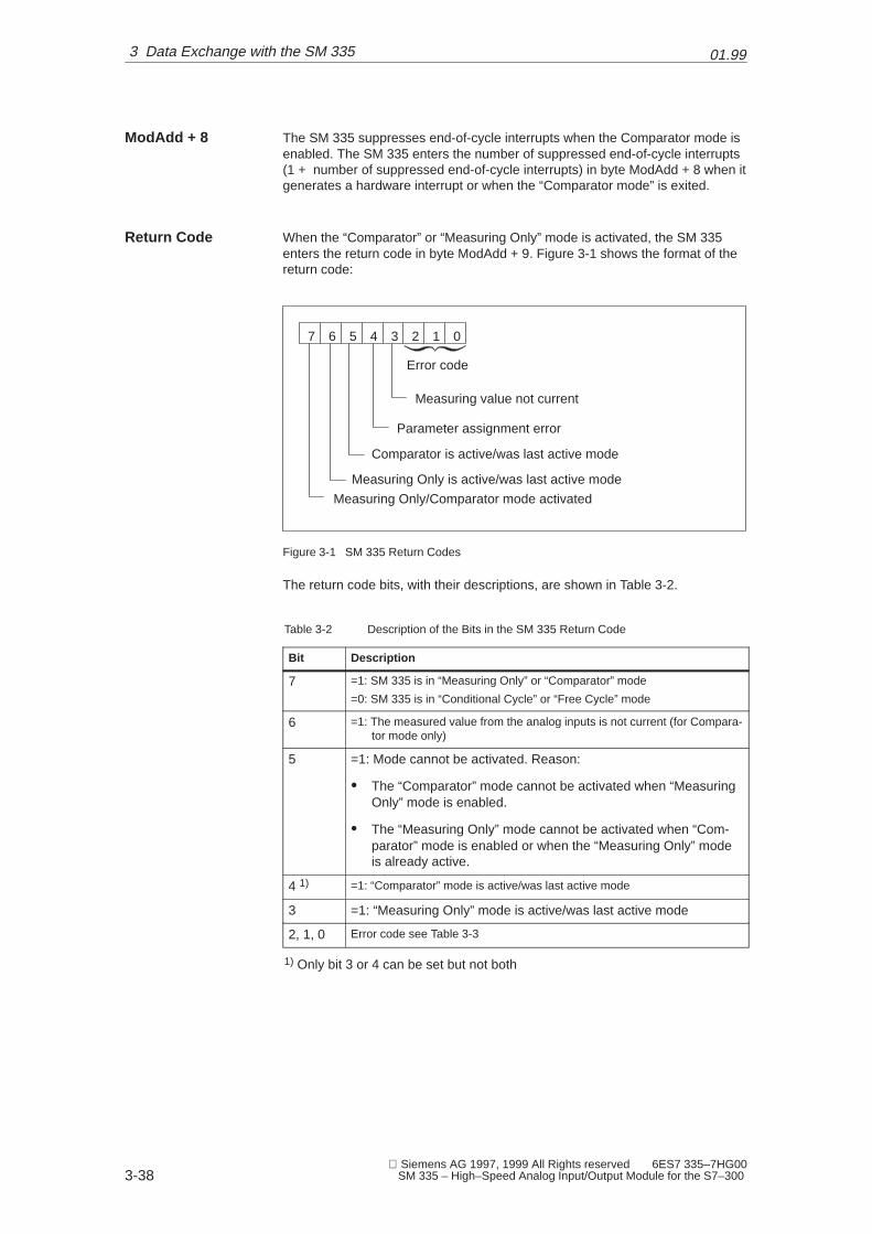
The SM 335 suppresses end-of-cycle interrupts when the Comparator mode isenabled. The SM 335 enters the number of suppressed end-of-cycle interrupts(1 + number of suppressed end-of-cycle interrupts) in byte ModAdd + 8 when itgenerates a hardware interrupt or when the “Comparator mode” is exited.
When the “Comparator” or “Measuring Only” mode is activated, the SM 335enters the return code in byte ModAdd + 9. Figure 3-1 shows the format of thereturn code:
7 6 5 4 3 2 1 0
Measuring value not current
Parameter assignment error
Measuring Only is active/was last active mode
Measuring Only/Comparator mode activated
Comparator is active/was last active mode
Error code
Figure 3-1 SM 335 Return Codes
The return code bits, with their descriptions, are shown in Table 3-2.
Table 3-2 Description of the Bits in the SM 335 Return Code
Bit Description
7 =1: SM 335 is in “Measuring Only” or “Comparator” mode
=0: SM 335 is in “Conditional Cycle” or “Free Cycle” mode
6 =1: The measured value from the analog inputs is not current (for Compara-tor mode only)
5 =1: Mode cannot be activated. Reason:
� The “Comparator” mode cannot be activated when “MeasuringOnly” mode is enabled.
� The “Measuring Only” mode cannot be activated when “Com-parator” mode is enabled or when the “Measuring Only” modeis already active.
4 1) =1: “Comparator” mode is active/was last active mode
3 =1: “Measuring Only” mode is active/was last active mode
2, 1, 0 Error code see Table 3-3
1) Only bit 3 or 4 can be set but not both
ModAdd + 8
Return Code
3 Data Exchange with the SM 335

01.99
3-39 Siemens AG 1997, 1999 All Rights reserved 6ES7 335–7HG00 SM 335 – High–Speed Analog Input/Output Module for the S7–300
Table 3-3 Meaning of Bits 0, 1, 2 in the return code of the SM 335
Bit2 Bit1 Bit0 Meaning
0 0 0 No error.
0 0 1 Parameter for operating mode ‘Comparator’ errored (noanalog input designated as comparator input).
0 1 0 Analog input to be used for measuring is disabled.
0 1 1 Error detected at the analog input assigned to the com-parator while ‘Comparator’ mode was in force.
1 0 0 Operating mode exited. Reason:
� Comparator: Comparator time expired
� Measuring Only: Measurement at one analog input:60 ms expired.
Measurement at 2, 3 or 4 analog inputs: 40 ms expi-red.
1 0 1 ‘Comparator’ mode exited because new parameterswere passed via system function to the SM 335.
Note
The return code is B#16#FF in the event of a total SM 335 failure.
3 Data Exchange with the SM 335
01.99
3-40 Siemens AG 1997, 1999 All Rights reserved 6ES7 335–7HG00
SM 335 – High–Speed Analog Input/Output Module for the S7–300
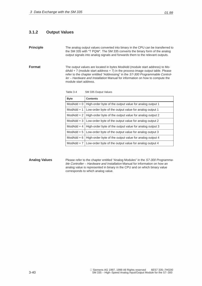
3.1.2 Output Values
The analog output values converted into binary in the CPU can be transferred tothe SM 335 with “T PQW”. The SM 335 converts the binary form of the analogoutput signals into analog signals and forwards them to the relevant outputs.
The output values are located in bytes ModAdd (module start address) to Mo-dAdd + 7 (module start address + 7) in the process-image output table. Pleaserefer to the chapter entitled “Addressing” in the S7-300 Programmable Control-ler – Hardware and Installation Manual for information on how to compute themodule start address.
Table 3-4 SM 335 Output Values
Byte Contents
ModAdd + 0 High-order byte of the output value for analog output 1
ModAdd + 1 Low-order byte of the output value for analog output 1
ModAdd + 2 High-order byte of the output value for analog output 2
ModAdd + 3 Low-order byte of the output value for analog output 2
ModAdd + 4 High-order byte of the output value for analog output 3
ModAdd + 5 Low-order byte of the output value for analog output 3
ModAdd + 6 High-order byte of the output value for analog output 4
ModAdd + 7 Low-order byte of the output value for analog output 4
Please refer to the chapter entitled “Analog Modules” in the S7-300 Programma-ble Controller – Hardware and Installation Manual for information on how ananalog value is represented in binary in the CPU and on which binary valuecorresponds to which analog value.
Principle
Format
Analog Values
3 Data Exchange with the SM 335

01.99
3-41 Siemens AG 1997, 1999 All Rights reserved 6ES7 335–7HG00 SM 335 – High–Speed Analog Input/Output Module for the S7–300
3.2 Setting Parameters via S7 Configuration
You have plugged in the measuring range module. You can learn how to do thisin the S7-300 Programmable Controller – Hardware and Installation Manual.Section 1.4 describes the measuring ranges to be set.
If the SM 335 is not offered for selection under S7 Configuration, enter theMLFB Number.
Confirm with the Enter key. The SM 335 parameters will then be displayed.
Measuring RangeModule
S7 Configuration
3 Data Exchange with the SM 335
01.99
3-42 Siemens AG 1997, 1999 All Rights reserved 6ES7 335–7HG00
SM 335 – High–Speed Analog Input/Output Module for the S7–300
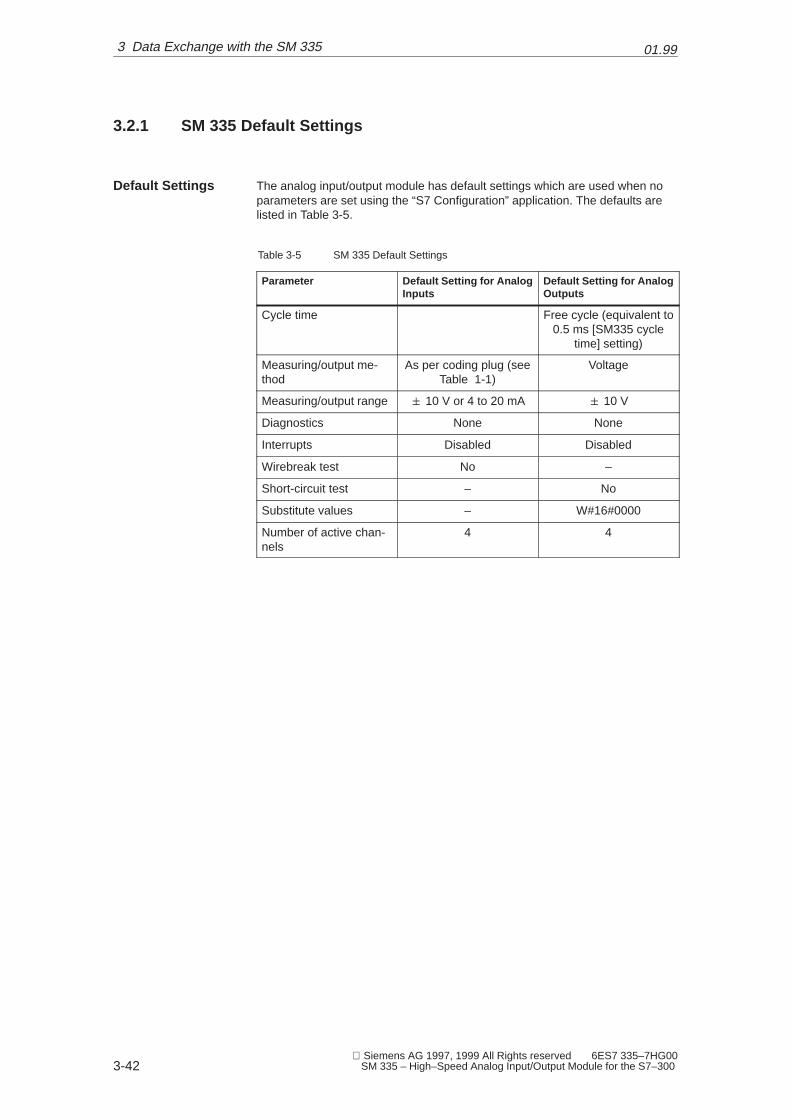
3.2.1 SM 335 Default Settings
The analog input/output module has default settings which are used when noparameters are set using the “S7 Configuration” application. The defaults arelisted in Table 3-5.
Table 3-5 SM 335 Default Settings
Parameter Default Setting for AnalogInputs
Default Setting for AnalogOutputs
Cycle time Free cycle (equivalent to0.5 ms [SM335 cycle
time] setting)
Measuring/output me-thod
As per coding plug (seeTable 1-1)
Voltage
Measuring/output range � 10 V or 4 to 20 mA � 10 V
Diagnostics None None
Interrupts Disabled Disabled
Wirebreak test No –
Short-circuit test – No
Substitute values – W#16#0000
Number of active chan-nels
4 4
Default Settings
3 Data Exchange with the SM 335
01.99
3-43 Siemens AG 1997, 1999 All Rights reserved 6ES7 335–7HG00 SM 335 – High–Speed Analog Input/Output Module for the S7–300
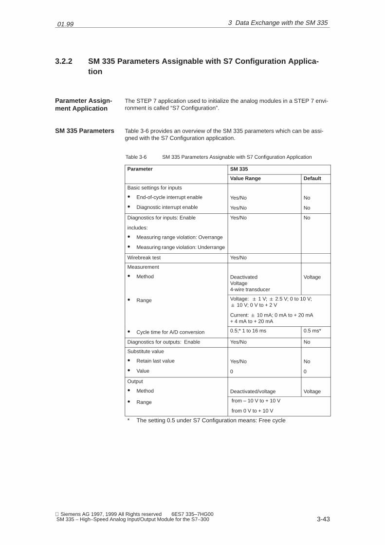
3.2.2 SM 335 Parameters Assignable with S7 Configuration Applica-tion
The STEP 7 application used to initialize the analog modules in a STEP 7 envi-ronment is called “S7 Configuration”.
Table 3-6 provides an overview of the SM 335 parameters which can be assi-gned with the S7 Configuration application.
Table 3-6 SM 335 Parameters Assignable with S7 Configuration Application
Parameter SM 335
Value Range Default
Basic settings for inputs
� End-of-cycle interrupt enable
� Diagnostic interrupt enable
Yes/No
Yes/No
No
No
Diagnostics for inputs: Enable
includes:
� Measuring range violation: Overrange
� Measuring range violation: Underrange
Yes/No No
Wirebreak test Yes/No
Measurement
� Method DeactivatedVoltage4-wire transducer
Voltage
� Range Voltage: � 1 V; � 2.5 V; 0 to 10 V;� 10 V; 0 V to + 2 V
Current: � 10 mA; 0 mA to + 20 mA + 4 mA to + 20 mA
� Cycle time for A/D conversion 0.5;* 1 to 16 ms 0.5 ms*
Diagnostics for outputs: Enable Yes/No No
Substitute value
� Retain last value
� Value
Yes/No
0
No
0
Output
� Method Deactivated/voltage Voltage
� Range from – 10 V to + 10 V
from 0 V to + 10 V
* The setting 0.5 under S7 Configuration means: Free cycle
Parameter Assign-ment Application
SM 335 Parameters
3 Data Exchange with the SM 335
01.99
3-44 Siemens AG 1997, 1999 All Rights reserved 6ES7 335–7HG00
SM 335 – High–Speed Analog Input/Output Module for the S7–300
When you enable the end-of-cycle interrupt, the SM 335 generates a hardwareinterrupt after A/D conversion of the active channels. You can use this to call OB40 at fixed intervals. You can set the cycle time for the A/D conversion. The SM335 can generate the end-of-cycle interrupt starting from a cycle time for A/Dconversion of 1 ms.
When diagnostic interrupts are enabled, the SM 335 generates a diagnosticinterrupt as soon as an error is found.
If the diagnostics for inputs are enabled, the SM 335 checks for common-modeerrors and measuring range violations. The wirebreak test must be activatedseparately. When you enable diagnostics for the outputs, the SM 335 executesa short-circuit test on the outputs.
You can activate the wirebreak test for any analog input. A wirebreak test ispossible in measuring ranges 4 to 20 mA and 0 to 10 V (when the A/D conver-sion cycle time is 2 ms or longer).
When the CPU is at STOP or executing the startup routine, the SM 335 outputsthe substitute value to the relevant analog output until a new value is specified.The SM 335 uses the following as substitute value:
� 0 V or
� the analog value last output.
You can specify whether the SM 335 is to retain the last analog value or output0 V.
The parameters created via S7 Configuration are stored in the CPU when trans-ferred from the programming device to the S7-300. At an operating mode transi-tion from STOP to RUN, these parameters are transferred to the relevant analogmodules.
End-of-Cycle Inter-rupt Enable
Diagnostic Inter-rupt Enable
Diagnostics Ena-ble
Wirebreak Test
Substitute ValueOutput
Transferring Para-meters
3 Data Exchange with the SM 335

01.99
3-45 Siemens AG 1997, 1999 All Rights reserved 6ES7 335–7HG00 SM 335 – High–Speed Analog Input/Output Module for the S7–300
3.3 Modifying SM 335 Parameters Using System Function 55
In RUN mode of the CPU, you can modify some parameters (dynamic parame-ters) via system function commands. However, after a mode transition fromRUN to STOP and STOP to RUN, the parameters generated with ‘S7 Configu-ration’ are back in force again.
The SM 335 parameters are 16 bytes long and are divided into two data re-cords. These parameters must be stored in a data area on the CPU (for exam-ple, in a bit memory or in a data block). System function 55 WR_PARAM is usedto transfer the parameters to the SM 335.
Note
You must always initialize the SM 335 parameters with S7 Configuration beforepassing them with system function 55. Reason: The system function accessesSDB 100 to SDB 103, which are generated with S7 Configuration.
The SM 335 parameters are stored in two data records.
Data record 0 of the SM 35 is 2 bytes long and contains the static parameters ofthe SM 335. You cannot modify these parameters with system function 55.
Data record 1 contains the dynamic parameters of the SM 335. You can modifythese parameters with system function 55.
Byte 11 of data record 1 is used for switching to the special operating modes. Inthe Free Cycle and Conditional Cycle modes, byte 11 has the value B#16#00.
S7 Configuration
Parameters
Data Records
Data Record 0
Data Record 1
Dynamic Measu-ring Cycle Byte
3 Data Exchange with the SM 335
01.99
3-46 Siemens AG 1997, 1999 All Rights reserved 6ES7 335–7HG00
SM 335 – High–Speed Analog Input/Output Module for the S7–300
3.3.1 SM 335 Parameters in the Free Cycle and Conditional Cycle Mo-des
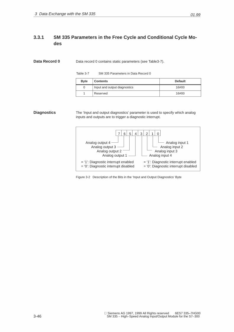
Data record 0 contains static parameters (see Table3-7).
Table 3-7 SM 335 Parameters in Data Record 0
Byte Contents Default
0 Input and output diagnostics 16#00
1 Reserved 16#00
The ‘Input and output diagnostics’ parameter is used to specify which analoginputs and outputs are to trigger a diagnostic interrupt.
7 6 5 4 3 2 1 0
Analog input 1Analog input 2
Analog input 3Analog input 4
Analog output 4Analog output 3
Analog output 2Analog output 1
= ‘1’: Diagnostic interrupt enabled= ‘0’: Diagnostic interrupt disabled
= ‘1’: Diagnostic interrupt enabled= ‘0’: Diagnostic interrupt disabled
Figure 3-2 Description of the Bits in the ‘Input and Output Diagnostics’ Byte
Data Record 0
Diagnostics
3 Data Exchange with the SM 335

01.99
3-47 Siemens AG 1997, 1999 All Rights reserved 6ES7 335–7HG00 SM 335 – High–Speed Analog Input/Output Module for the S7–300
3.3.2 SM 335 Parameters in the Free Cycle and Conditional Cycle Mo-des
Data record 1 contains dynamic parameters (see Table 3-8).
Table 3-8 SM 335 Parameters in Data Record 1
Byte Contents Default
0 Interrupt and substitute value output B#16#00
1 Reserved B#16#00
2 Measuring range for analog input 1 B#16#19
3 Measuring range for analog input 2 B#16#19
4 Measuring range for analog input 3 Depends on coding plug setting
5 Measuring range for analog input 4lug setting
(see Table 3-9)
6 Output range for analog output 1 B#16#19
7 Output range for analog output 2 B#16#19
8 Output range for analog output 3 B#16#19
9 Output range for analog output 4 B#16#19
10 Measuring cycle time B#16#01
11 Fixed at B#16#00 in the Free Cycle and Con-ditional Cycle modes
B#16#00
12 Wirebreak test B#16#00
13 Monitoring time for interval B#16#00
Data Record 1
3 Data Exchange with the SM 335

01.99
3-48 Siemens AG 1997, 1999 All Rights reserved 6ES7 335–7HG00
SM 335 – High–Speed Analog Input/Output Module for the S7–300
This parameter defines the following:
� Whether a hardware interrupt (conditional cycle only) is to be generated
� Whether a diagnostics interrupt is to be generated
� Whether the last valid analog value or 0 V is to be output as substitute va-lue.
7 6 5 4 3 2 1 0Byte 0
Analog output 1Analog output 2
Analog output 3Analog output 4
= ‘1’: Substitute value = Last analog value= ‘0’: 0 V is output as substitute value
Enable hardware interruptEnable diagnostic interrupt
Substitute value out-put
Figure 3-3 Description of the Bits in the ‘Interrupt and Substitute Value Output’ Byte
The default parameters for the measuring range of the analog inputs depend onthe setting on the SM 335’s coding plug.
Table 3-9 Parameters for the Measuring Range of the Analog Inputs
Coding Plug SettingSM 335 Default Parameters forthe Measuring Ranges of Ana-log Inputs
Permissible Parametersand Measuring Ranges
A
Byte 2: 16#19 (Voltage)
Byte 3: 16#19 (Voltage)
Byte 4: 16#19 (Voltage)
Byte 5: 16#23 (Current)For measuring voltage
16#14: – 1 V to + 1 V
BThis coding plug set-ting is not allowed.
Byte 2: 16#00
Byte 3: 16#00
Byte 4: 16#00
Byte 5: 16#00
16#14: – 1 V to + 1 V
16#15: – 2.5 V to + 2.5 V
16#18: 0 V to + 10 V
16#19: – 10 V to + 10 V
16#1C: 0 V to + 2 V
C
Byte 2: 16#19 (Voltage)
Byte 3: 16#19 (Voltage)
Byte 4: 16#23 (Current)
Byte 5: 16#23 (Current)
16#1C: 0 V to + 2 V
For measuring current
16#21: – 10 mA to + 10 mA
16#22: 0 mA to + 20 mA
D
Byte 2: 16#19 (Voltage)
Byte 3: 16#19 (Voltage)
Byte 4: 16#19 (Voltage)
Byte 5: 16#19 (Voltage)
16#22: 0 mA to + 20 mA
16#23: 4 mA to + 20 mA
Interrupt and Sub-stitute Value Out-put
Measuring Rangesfor Analog Inputs
3 Data Exchange with the SM 335

01.99
3-49 Siemens AG 1997, 1999 All Rights reserved 6ES7 335–7HG00 SM 335 – High–Speed Analog Input/Output Module for the S7–300
The ‘Measuring Cycle Time’ parameter specifies the length of a measuring cy-cle. Permissible values are those from 16#01 to 16#00. The default value is16#01. The value 16#01 specifies a free cycle, that is, a measuring cycle has aduration of about 0.9 ms. The value 16#02 corresponds to a measuring cycle of1 ms, 16#03 to a measuring cycle of 1.5 ms, and so on. 16#00 corresponds to ameasuring cycle of 16 ms.
Note
Measuring cycle time of 1 ms:
Prior to the first measurement (channel 4), modified output values are output.The measurements are performed subsequently. At a measuring cycle time of1 ms, diagnoses are not performed for short circuit, underflow and overflow inorder to serve all output and input channels within 1 ms. The comparator func-tion is not executed at a cycle of 1 ms. Owing to the missing time, comparator 1is not possible.
The ‘Dynamic Measuring Cycle Control’ parameter cannot be set with the S7Configuration application. In normal operation, this byte always has the valueB#16#00.
= 0: Switch mode on= 1: Switch mode off
7 6 5 4 3 2 1 0
‘Comparator‘mode
Analog inputComparator 1
00 – Analog input 101 – Analog input 210 – Analog input 311 – Analog input 4
Analog inputComparator 2
00 – Analog input 101 – Analog input 210 – Analog input 311 – Analog input 4
Figure 3-4 Meaning of the Bits in the Dynamic Measuring Cycle Control Byte
Measuring CycleTime
Dynamic Measu-ring Cycle Control
3 Data Exchange with the SM 335
01.99
3-50 Siemens AG 1997, 1999 All Rights reserved 6ES7 335–7HG00
SM 335 – High–Speed Analog Input/Output Module for the S7–300
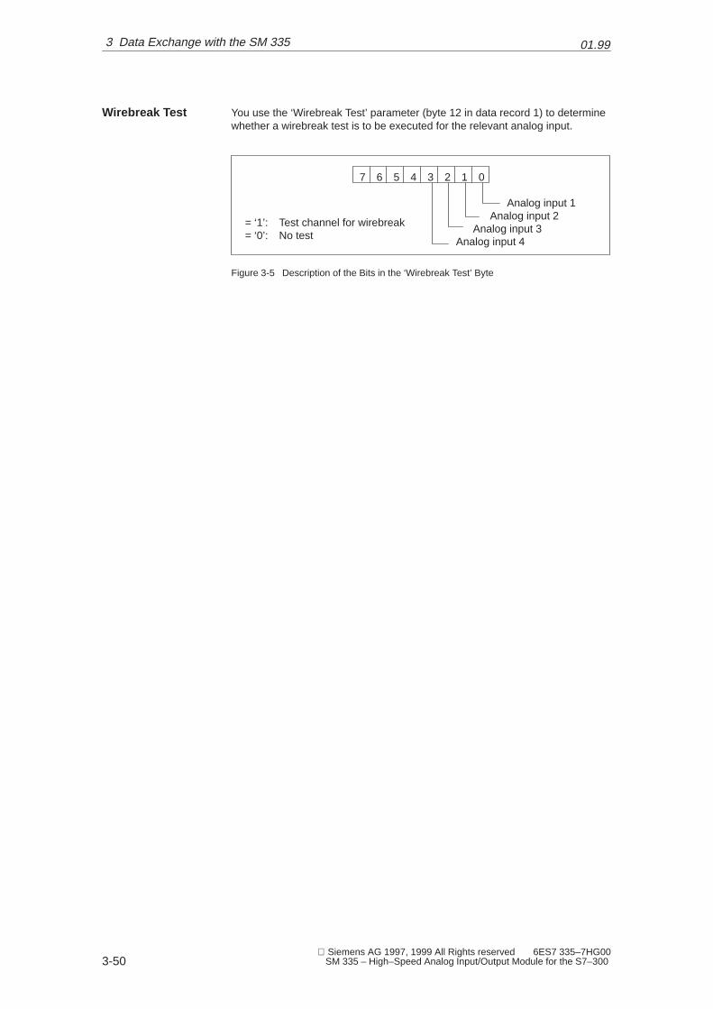
You use the ‘Wirebreak Test’ parameter (byte 12 in data record 1) to determinewhether a wirebreak test is to be executed for the relevant analog input.
7 6 5 4 3 2 1 0
Analog input 1Analog input 2
Analog input 3Analog input 4
= ‘1’: Test channel for wirebreak= ‘0’: No test
Figure 3-5 Description of the Bits in the ‘Wirebreak Test’ Byte
Wirebreak Test
3 Data Exchange with the SM 335

01.99
3-51 Siemens AG 1997, 1999 All Rights reserved 6ES7 335–7HG00 SM 335 – High–Speed Analog Input/Output Module for the S7–300
3.3.3 SM 335 Parameters for the ‘Comparator’ Mode
Chapter 5 describes how to switch to the ‘Comparator’ mode.
The parameters for “Comparator” mode can be passed with system function 55WR_PARA only.
The parameters that can be switched dynamically are stored in data record 1(see Table 3-10).
Table 3-10 SM 335’s Data Record 1 for “Comparator” Mode
Byte Contents
0 High-order byte of analog output value 1
1 Low-order byte of analog output value 1
2 High-order byte of analog output value 2
3 Low-order byte of analog output value 2
4 High-order byte of analog output value 3
5 Low-order byte of analog output value 3
6 High-order byte of comparison value for “Comparator 1”
7 Low-order byte of comparison value for “Comparator 1”
8 High-order byte of comparison value for “Comparator 2”
9 Low-order byte of comparison value for “Comparator 2”
10 Comparator time
11 Dynamic measuring cycle control
12 Comparator control byte
13 Reserved
During the time the comparator is active, the SM 335 cannot generate a hard-ware interrupt for the end-of-cycle. It can therefore happen that the SM 335does not generate an end-of-cycle interrupt for an extended period. You canuse the comparator time to specify how long the comparator can remain active.If the comparator is active and the comparator time has expired, the SM 335switches back autonomously to the ‘conditional cycle’ or ‘free cycle’ mode. Thecomparator time is specified in milliseconds (1 = 1 ms, 2 = 2 ms, to 0 = 256 ms).
Switching
Restrictions
Data Record 1
Comparator Time
3 Data Exchange with the SM 335

01.99
3-52 Siemens AG 1997, 1999 All Rights reserved 6ES7 335–7HG00
SM 335 – High–Speed Analog Input/Output Module for the S7–300
The ‘Dynamic measuring cycle control’ byte has the following assignments inthe ‘Comparator’ mode:
= 0: Switch mode on= 1: Switch mode off
7 6 5 4 3 2 1 0
‘Comparator‘mode
Analog inputComparator 1
00 – Analog input 101 – Analog input 210 – Analog input 311 – Analog input 4
Analog inputComparator 2
00 – Analog input 101 – Analog input 210 – Analog input 311 – Analog input 4
Figure 3-6 Meaning of the Bits in the Dynamic Measuring Cycle Control Byte
Bits 4 and 6 in the dynamic measuring cycle control byte must be ‘0’. You canset only one of bits 0 to 4 to ‘0’. The relevant analog input is used as input forthe comparator. If you set more than one bit to ‘0’, the SM 335 uses the analoginput with the lowest value bit.
You can additionally check the comparator in the comparator check byte. Thecomparator check byte has the following structure:
7 6 5 4 3 2 1 0
Analog output 1
Analog output 2
Analog output 3
Analog output 4
Direction
Comparator 1
Comparator 2
Hardwareinterrupt
Figure 3-7 Comparator Check Byte for the ‘Comparator’ Mode
If bit 7 in the comparator check byte is set to ‘0’, the comparison is made in thedirection of rising analog values. If bit 7 is set to ‘1’, the comparison is made inthe direction of falling analog values.
Dynamic Measu-ring Cycle Control
Comparator CheckByte
Direction
3 Data Exchange with the SM 335

01.99
3-53 Siemens AG 1997, 1999 All Rights reserved 6ES7 335–7HG00 SM 335 – High–Speed Analog Input/Output Module for the S7–300
You switch comparator 1 and 2 on with the Comparator 1 and 2 bits (see Ta-ble 3-11).
Table 3-11 Checking the Comparator with Check Bits 1 and 2
Bit 6 Bit 5 Behavior of the Comparator
1 1 Switch on comparators 1 and 2 in succession
0 1 Switch on comparator 2
1 0 Switch on comparator 1
0 0 ‘Comparator’ mode exited immediately
If you set bit 4 in the comparator check byte to ‘1’, the SM 335 generates ahardware interrupt at the reversing point.
In bits 0 to 3, you specify the analog outputs that the specified values (byte 0 to7 in the table) are to be output to.
� Bit i = ’1’: Specified value is output
� Bit i = 0: Old analog value is retained
You can set up to 3 bits. The analog values are output until a new value is writ-ten to the output.
Comparator 1 andComparator 2
Hardware Interrupt
Analog Output
3 Data Exchange with the SM 335

01.99
3-54 Siemens AG 1997, 1999 All Rights reserved 6ES7 335–7HG00
SM 335 – High–Speed Analog Input/Output Module for the S7–300
3.3.4 SM 335 Parameters for “Measuring Only” Mode
Chapter 5 describes how to switch to the ‘Measuring Only’ mode.
You transfer the dynamic SM 335 parameters for the ‘Measuring Only’ mode indata record 1.
Note
The parameters in data record 1 that you transfer to switch to the ‘MeasuringOnly’ mode must be identical with the parameters that you have transferred forthe Free Cycle or Conditional Cycle modes, with the exception of byte 11.
Table 3-12 SM 335’s Data Record 1 for “Measuring Only” Mode
Byte Contents
0
1
2
3
4Assigned as in the Free Cycle and Conditional Cycle modes
5Assigned as in the Free Cycle and Conditional Cycle modes
(see Table 3-8)6
(see Table 3-8)
7
8
9
10
11 Dynamic measuring cycle control
12 Assigned as in the Free Cycle and Conditional Cycle modes
13 (see Table 3-8)
Byte 11 ‘Dynamic measuring cycle control’ has two tasks:
� To switch on the ‘Measuring Only’ mode
� To disable/enable analog inputs
Switching
Data Record 1
Dynamic Measu-ring Cycle Control
3 Data Exchange with the SM 335

01.99
3-55 Siemens AG 1997, 1999 All Rights reserved 6ES7 335–7HG00 SM 335 – High–Speed Analog Input/Output Module for the S7–300
To switch on the ‘Measuring Only’ mode, you must transfer all the SM 335 para-meters and set the following bits in byte 11:
7 6 5 4 3 2 1 0
‘Measuring Only’ mode
= 0: Switch mode off= 1:Switch mode on
Figure 3-8 Dynamic Measuring Cycle Control for ‘Measuring Only’ Mode
You disable the associated analog input with bits 0 to 3. The default for bits 0 to3 is ‘0’. Setting a bit to ‘1’ diables the associated analog input. If you disable 3analog inputs, it is possible to attain a measuring cycle time of under 0.5 ms.
7 6 5 4 3 2 1 0
Analog input 1Analog input 2
Analog input 3Analog input 4
= 1: Analog input disabled= 0: Analog input read in
‘Measuring Only’ mode
= 0: Switch mode off= 1: Switch mode on
Figure 3-9 Meaning of the Bits in the ‘Dynamic Measuring Cycle Control’ Byte
Switching on theOperating Mode
Dynamic Disablingof Analog Inputs
3 Data Exchange with the SM 335

01.99
3-56 Siemens AG 1997, 1999 All Rights reserved 6ES7 335–7HG00
SM 335 – High–Speed Analog Input/Output Module for the S7–300
3.4 Evaluating SM 335 Diagnostics
There are several methods of accessing SM 335 diagnostics:
� With an enabled diagnostics interrupt via the local data in OB 82
� With a hardware interrupt via the local data of the interrupt OB (for example,OB 40)
� By reading the diagnostics data with system function 59 (RD_REC)
If you have enabled the diagnostics interrupt for the SM 335 and the SM 335generates a diagnostics interrupt, the CPU processes OB 82. The local data ofOB 82 contain some of the diagnostics data of the SM 335.
If the SM 335 generates a hardware interrupt, this hardware interrupt can havetwo causes. The cause leading to the SM 335 interrupt, is stored in the localdata of OB 40 (see Section 3.4.1)
The complete diagnostics data of the SM 335 can be accessed via systemfunction 59. The structure of the diagnostics data is explained in Section 3.4.2.
Methods
Diagnostics Inter-rupt
Hardware Interrupt
Principle
3 Data Exchange with the SM 335

01.99
3-57 Siemens AG 1997, 1999 All Rights reserved 6ES7 335–7HG00 SM 335 – High–Speed Analog Input/Output Module for the S7–300
3.4.1 Hardware Interrupt
OB 40 is invoked when the SM 335 generates a hardware interrupt. Informationon the cause of the hardware interrupt is entered in the local data section of OB40.
The reasons for the hardware interrupt are entered in byte 8 of the local data(see Figure 3-10)
7 6 5 4 3 2 1 0
End-of-cycle interrupt
Interrupt triggered by comparator
Figure 3-10 Byte 8 in Local Data in the Event of a Hardware Interrupt Generated by the SM335
Table 3-13 End–of–cycle interrupt
Byte Contents Default
8 0000 0001B
9 not ussigned 0
10 Number of measuring cycles 1)
11 not ussigned 0
1) Remember of measuring cycles also be read–out from the input section ModAdd+8.
Table 3-14 Interrupt triggered by comparator
Byte Contents Default
8 0000 0010B
9 Comparator time [ms]
10 Measuring value low of Comparator 2
11 Measuring value high of Comparator 2
OB 40
Local Data
3 Data Exchange with the SM 335

01.99
3-58 Siemens AG 1997, 1999 All Rights reserved 6ES7 335–7HG00
SM 335 – High–Speed Analog Input/Output Module for the S7–300
3.4.2 Format of the Diagnostic Data for the SM 335
Following the system function 59 call, the SM 335 diagnostic data are availablein the specified memory area. The data are formatted as shown in Table 3-15.
Table 3-15 SM 335 Diagnostic Data
Byte Contents Default
0 Module diagnostic byte 1 16#40
1 Module diagnostic byte 2 Fixed: 16#35
2 Module diagnostic byte 3 16#00
3 Module diagnostic byte 4 16#00
4 Channel type: 16#00, 16#71 (input), 16#73 (output) 16#00
5 Number of diagnostic bits per channel Fixed: 16#35
6 Number of inputs/outputs Fixed: 16#08
7 Change in diagnostic byte for input/output(a ‘1’ bit corresponds to changes in bytes 8 to 15)
16#00
8 Channel-specific diagnostic byte for analog input 1 16#00
9 Channel-specific diagnostic byte for analog input 2 16#00
10 Channel-specific diagnostic byte for analog input 3 16#00
11 Channel-specific diagnostic byte for analog input 4 16#00
12 Channel-specific diagnostic byte for analog output 1 16#00
13 Channel-specific diagnostic byte for analog output 2 16#00
14 Channel-specific diagnostic byte for analog output 3 16#00
15 Channel-specific diagnostic byte for analog output 4 16#00
Format
3 Data Exchange with the SM 335

01.99
3-59 Siemens AG 1997, 1999 All Rights reserved 6ES7 335–7HG00 SM 335 – High–Speed Analog Input/Output Module for the S7–300
3.4.3 Module Diagnostic Byte 1
The SM 335’s module diagnostic byte 1 contains group error information. Thisbyte has the format shown in Figure 3-11.
7 6 5 4 3 2 1 0
Group fault
Internal fault
External fault
Channel fault
No 24 V load voltage
SM 335 not initialized
Invalid parameters
Figure 3-11 The SM 335’s Module Diagnostic Byte 1
Bit 0 in module diagnostic byte 1 is set when the SM 335 flags an error/fault (theonly exception being “SM 335 not initialized”).
Bit 1 is set in module diagnostic byte 1 when the SM 335 detects one of thefollowing:
� Watchdog
� EEPROM fault
� ADC/DAC error
Format
Group Fault
Internal Fault
3 Data Exchange with the SM 335

01.99
3-60 Siemens AG 1997, 1999 All Rights reserved 6ES7 335–7HG00
SM 335 – High–Speed Analog Input/Output Module for the S7–300
Bit 2 in module diagnostic byte 1 is set when one of the following errors/faultsoccurs:
� Coding plug not inserted
� Coding plug improperly inserted (default parameters do not coincide withcoding plug setting)
� External auxiliary power supply has failed
� Fault on one of the inputs
– Common-mode error
– Wirebreak
– Measuring range violation (overrange)
– Measuring range violation (underrange)
� Fault on one of the outputs (ground short)
If bit 3 in the module diagnostic byte has been set, the SM 335 has detected achannel-specific error in one of the channels. You will find more detailed infor-mation in the channel-specific diagnostics bytes (bytes 8 to 15).
Bit 4 in module diagnostic byte 1 is set when the 24 V load voltage has droppedbelow 10 V.
Bit 6 in module diagnostic byte 1 is set when no parameters were assigned forthe SM 335.
Bit 7 in module diagnostic byte 1 is set when the SM 335 was incorrectly initiali-zed, that is, the parameters do not coincide with the coding plug setting on themodule. This bit is set if parameter assignment failed (for instance when systemfunction WR_PARA is called to pass the parameters).
External Fault
Channel Error
No 24 V Load Vol-tage
SM 335 Not Initiali-zed
Invalid Parameters
3 Data Exchange with the SM 335
01.99
3-61 Siemens AG 1997, 1999 All Rights reserved 6ES7 335–7HG00 SM 335 – High–Speed Analog Input/Output Module for the S7–300
3.4.4 Module Diagnostic Byte 2
Module diagnostic byte 2 always contains the fixed value 16#35.Contents
3 Data Exchange with the SM 335

01.99
3-62 Siemens AG 1997, 1999 All Rights reserved 6ES7 335–7HG00
SM 335 – High–Speed Analog Input/Output Module for the S7–300
3.4.5 Module Diagnostic Byte 3
Two different errors are flagged in module diagnostic byte 3 (see Figure 3-12).
7 6 5 4 3 2 1 0
Coding plug not/not properly inserted
Hardware fault
Operational state
Figure 3-12 Module Diagnostic Byte 3
Bit 0 is set in module diagnostic byte 3 when the SM 335 recognizes that nocoding plug has been inserted, or when the coding plug has not been properlyinserted.
Bit 2 is set in the module diagnostic bit if the SM 335 is in the Stop state.
Bit 3 in module diagnostic byte 3 is set when the SM 335 detects an internalhardware fault. In this case, the SM 335 outputs 0 V, and all inputs are set to7FFF or FF FF FF.
Format
Coding Plug Not/Not Properly Inser-ted
Operational state
Hardware Fault
3 Data Exchange with the SM 335

01.99
3-63 Siemens AG 1997, 1999 All Rights reserved 6ES7 335–7HG00 SM 335 – High–Speed Analog Input/Output Module for the S7–300
3.4.6 Module Diagnostic Byte 4
Two different errors are flagged in module diagnostic byte 4 (see Figure 3-13).
7 6 5 4 3 2 1 0
EEPROM fault
ADC/DAC error
Figure 3-13 Module Diagnostic Byte 4
Bit 2 is set in module diagnostic byte 4 when the SM 335 detects an internalerror in the EEPROM.
Bit 4 is set in module diagnostic byte 4 when the SM 335 detects an analog-di-gital or digital-analog conversion error.
Such an error might occur for one of three reasons:
� No 24 V load voltage or below 15 V
� EMC problem
� Internal hardware fault
Format
EEPROM Fault
ADC/DAC Error
3 Data Exchange with the SM 335
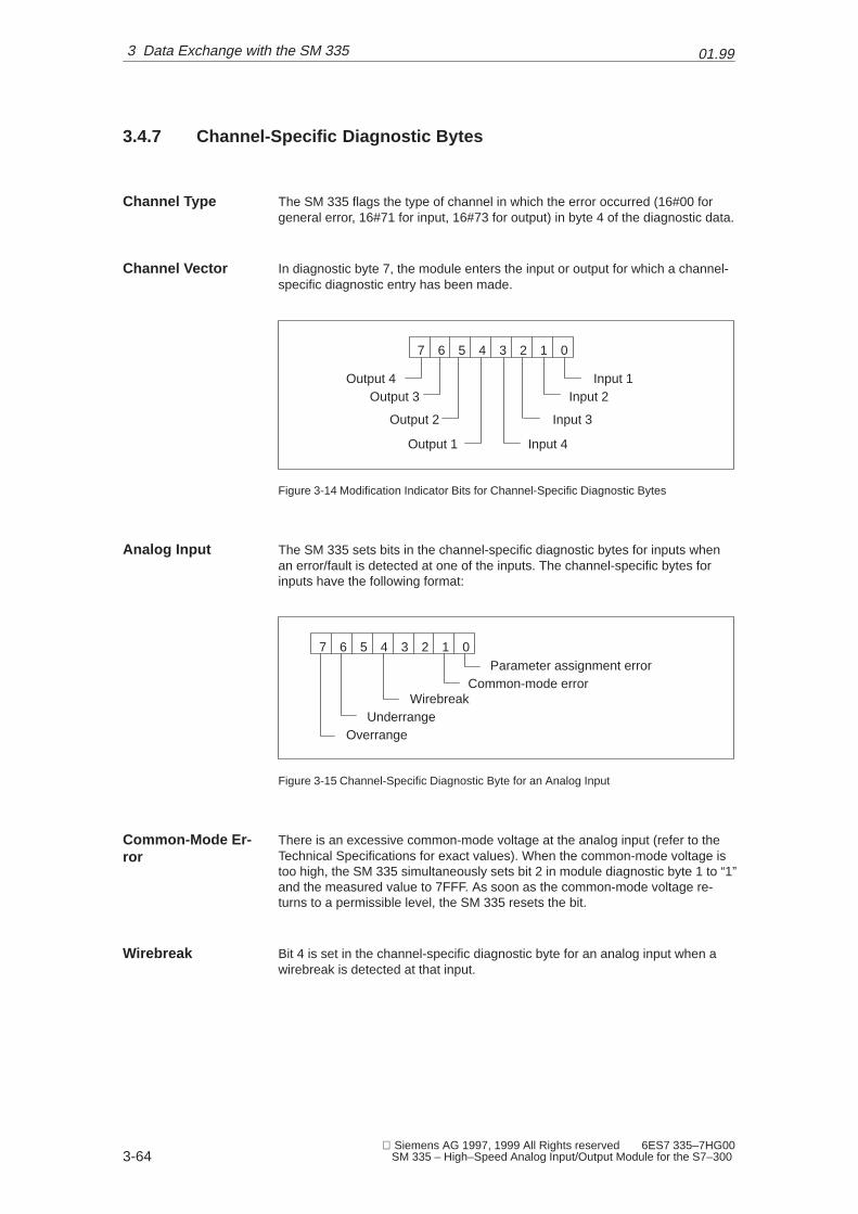
01.99
3-64 Siemens AG 1997, 1999 All Rights reserved 6ES7 335–7HG00
SM 335 – High–Speed Analog Input/Output Module for the S7–300
3.4.7 Channel-Specific Diagnostic Bytes
The SM 335 flags the type of channel in which the error occurred (16#00 forgeneral error, 16#71 for input, 16#73 for output) in byte 4 of the diagnostic data.
In diagnostic byte 7, the module enters the input or output for which a channel-specific diagnostic entry has been made.
7 6 5 4 3 2 1 0
Input 1Input 2
Input 3
Input 4
Output 4Output 3
Output 2
Output 1
Figure 3-14 Modification Indicator Bits for Channel-Specific Diagnostic Bytes
The SM 335 sets bits in the channel-specific diagnostic bytes for inputs whenan error/fault is detected at one of the inputs. The channel-specific bytes forinputs have the following format:
7 6 5 4 3 2 1 0
Common-mode errorWirebreak
OverrangeUnderrange
Parameter assignment error
Figure 3-15 Channel-Specific Diagnostic Byte for an Analog Input
There is an excessive common-mode voltage at the analog input (refer to theTechnical Specifications for exact values). When the common-mode voltage istoo high, the SM 335 simultaneously sets bit 2 in module diagnostic byte 1 to “1”and the measured value to 7FFF. As soon as the common-mode voltage re-turns to a permissible level, the SM 335 resets the bit.
Bit 4 is set in the channel-specific diagnostic byte for an analog input when awirebreak is detected at that input.
Channel Type
Channel Vector
Analog Input
Common-Mode Er-ror
Wirebreak
3 Data Exchange with the SM 335

01.99
3-65 Siemens AG 1997, 1999 All Rights reserved 6ES7 335–7HG00 SM 335 – High–Speed Analog Input/Output Module for the S7–300
The measured value at the input is checked for a range violation. Depending onthe direction of the range violation, the SM 335 sets either the overrange or theunderrange bit.
The SM 335 sets bits in the channel-specific diagnostic byte for an analog out-put when it detects a short circuit or a parameter assignment error at the analogoutput.
7 6 5 4 3 2 1 0
Short circuit on theanalog output
Parameter assignment error
Figure 3-16 Channel-Specific Diagnostic Byte for an Analog Output
�
Overrange and Un-derrange
Analog Output
3 Data Exchange with the SM 335

01.99
3-66 Siemens AG 1997, 1999 All Rights reserved 6ES7 335–7HG00
SM 335 – High–Speed Analog Input/Output Module for the S7–300
3 Data Exchange with the SM 335

4-67 Siemens AG 1997, 1999 All Rights reserved 6ES7 335–7HG00 SM 335 – High–Speed Analog Input/Output Module for the S7–300
Interval Counter Input
With an interval counter, you can measure intervals. You can use the duration ofan interval to calculate a speed, for example, if you know the path covered du-ring the interval. You can also acquire the signals of simple rotary sensors anddetermine the rotational speed from the interval duration.
You can acquire the following with the interval counter input:
� Number of intervals
� Duration of an interval
We deal with the following topics in this chapter:
Topic Section
Principle of an interval counter 4.1
Principle of measuring with an interval counter 4.2
Wiring the interval counter input 4.3
Parameterizing the SM 335 interval counter input 4.4
Values of the interval counter 4.5
Example of determining a rotational speed with the interval counter 4.6
Purpose
Principle
In this Chapter
4

01.99
4-68 Siemens AG 1997, 1999 All Rights reserved 6ES7 335–7HG00
SM 335 – High–Speed Analog Input/Output Module for the S7–300
4.1 Interval Counter Input
What is an interval counter? On the SM 335, an interval counter counts thenumber of intervals. What does this mean in practice? Figure 4-1 shows a sim-ple sensor. The sensor returns a “1” when light falls through one of the slots inthe disc. When the disc rotates, the sensor returns the signal shown in the dia-gram.
0
1
t1
0 1 2 3 4 5 6 7
t2
t3t4
Slotted disc
Signal
Signal
Time t
Interval coun-ter
Interval duration ti
Figure 4-1 Simple Sensor, for Instance with a Slotted Disc on a Shaft
The interval counter counts the number of intervals. The first interval begins onthe first transition from “0” to “1” (positive-going edge), and ends with the nextpositive-going edge, which is also the start of the next interval.
The interval-counting procedure also includes acquiring the interval duration.On each positive-going edge, a counter is started which is incremented by 1every 0.5 �s until the next positive-going edge is detected. This is called an in-terval duration counter.
Principle
Interval Counter
Interval DurationCounter
4 Interval Counter Input

01.99
4-69 Siemens AG 1997, 1999 All Rights reserved 6ES7 335–7HG00 SM 335 – High–Speed Analog Input/Output Module for the S7–300
4.2 Principles of Measuring with the Interval Counter
Pulses from a simple sensor are acquired via an analog input. The sensormight, for example, be located on the barrel extruder of an injection moldingmachine. You can determine the rotational speed of the barrel from the intervalbetween two pulses.
The SM 335 measures the amount of time (interval) that passes between twopulses. The SM 335 determines the interval with a resolution of 0.5 �s. Thenumber of intervals measured is also tallied.
If you know the number of pulses the sensor generates for each rotation of thebarrel extruder, you can compute the speed at which the barrel extruder rotates.
N = 16 pulses are generated per barrel extruder rotation (N is also referred to asthe sensor’s number of pulses per rotation). The interval between two pulses is50,000 increments. The rotational speed of the barrel extruder is thus computedas follows:
v �
1T·N
�
150000·0.5�s·16
� 2.5Us � 150 U
min
The interval timer returns a 3-byte value, enabling representation of up to FF FFFF (16777215 in decimal representation). For N = 1, the critical frequency thuscomputes to:
v �
1T·N
�
116777215·0.5�s
� 0, 1192, 51s � 7.15 Umin
The upper limiting value results from the condition that the interval between twopositive-going edges must be at least 2.5 ms. The critical frequency is thus 400Hz (equivalent to 24,000 rotations per minute).
These limiting values apply for sensors which generate one pulse per rotation.When sensors generating several pulses per rotation are used, you must re-as-sess the critical frequencies. A number of examples are listed in Table 4-1.
Table 4-1 Limiting Values for Different Numbers of Pulses (N)
N Lower Limit Upper Limit
1 7.15 rev/min 24000 rev/min
4 1.79 rev/min 6000 rev/min
8 0.89 rev/min 3000 rev/min
16 0.85 rev/min 1500 rev/min
Purpose
Principle
Example
Lower Limiting Va-lue
Upper Limiting Va-lue
4 Interval Counter Input
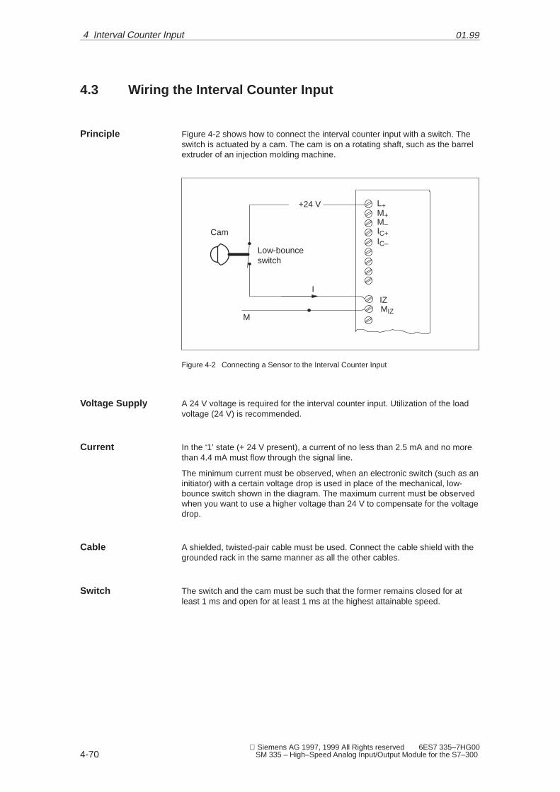
01.99
4-70 Siemens AG 1997, 1999 All Rights reserved 6ES7 335–7HG00
SM 335 – High–Speed Analog Input/Output Module for the S7–300
4.3 Wiring the Interval Counter Input
Figure 4-2 shows how to connect the interval counter input with a switch. Theswitch is actuated by a cam. The cam is on a rotating shaft, such as the barrelextruder of an injection molding machine.
L+M+M–IC+IC–
+24 V
IZMIZ
M
I
Low-bounceswitch
Cam
Figure 4-2 Connecting a Sensor to the Interval Counter Input
A 24 V voltage is required for the interval counter input. Utilization of the loadvoltage (24 V) is recommended.
In the ‘1’ state (+ 24 V present), a current of no less than 2.5 mA and no morethan 4.4 mA must flow through the signal line.
The minimum current must be observed, when an electronic switch (such as aninitiator) with a certain voltage drop is used in place of the mechanical, low-bounce switch shown in the diagram. The maximum current must be observedwhen you want to use a higher voltage than 24 V to compensate for the voltagedrop.
A shielded, twisted-pair cable must be used. Connect the cable shield with thegrounded rack in the same manner as all the other cables.
The switch and the cam must be such that the former remains closed for atleast 1 ms and open for at least 1 ms at the highest attainable speed.
Principle
Voltage Supply
Current
Cable
Switch
4 Interval Counter Input
01.99
4-71 Siemens AG 1997, 1999 All Rights reserved 6ES7 335–7HG00 SM 335 – High–Speed Analog Input/Output Module for the S7–300
The interval counter input is galvanically isolated from the other connections,and can thus form no ground loops with them.
The input is sufficiently grounded when the 24 V load voltage is used to power itand the frame of the 24 V load voltage source has been grounded (refer to theS7-300 Programmable Controller – Hardware and Installation Manual for de-tails).
Grounding
4 Interval Counter Input
01.99
4-72 Siemens AG 1997, 1999 All Rights reserved 6ES7 335–7HG00
SM 335 – High–Speed Analog Input/Output Module for the S7–300
4.4 Initializing the SM 335’s Interval Counter
The interval counter requires no parameters. The pulse input functions indepen-dently of the parameters assigned to the remaining analog channels.This is whyyou need not parameterize the pulse input. During reparameterization, you canparameterize the external counter with a timeout.
The parameterized timeout is 8.388/256 seconds multiplied with the value sto-red in the last byte of Ds1:
� By default, 00 corresponds to 8,388 s,
� 1 corresponds to 0,032765625 s
� 2 corresponds to 0,016382812 s
� etc.
Parameter Assign-ments
4 Interval Counter Input

01.99
4-73 Siemens AG 1997, 1999 All Rights reserved 6ES7 335–7HG00 SM 335 – High–Speed Analog Input/Output Module for the S7–300
4.5 Interval Counter Values
The values which the SM 335 computes for the pulse input are stored at the I/Oaddress module start address + 12.
Table 4-2 Pulse Input Values
Module Address Contents
+ 12 Interval counter
+ 13 Interval duration, byte 1
+ 14 Interval duration, byte 2
+ 15 Interval duration, byte 3
The interval counter is a ring counter for measured intervals. The first pulse toarrive initializes the counter internally. When the second pulse arrives, the coun-ter is incremented by ‘1’. Each subsequent pulse increments the counter by ‘1’.
The SM 335 stores the number of intervals acquired to date in the data byte at“module address + 12”. This data byte is ‘0’ as long as no interval has beendetected. Each time an interval is detected, the counter is incremented by ‘1’.
During an interval, the SM 335 counts the time until the interval ends in incre-ments, or time slices, of 0.5 µs. The SM 335 enters the duration of the interval inthree bytes, beginning with the byte at “module start address + 13”. The byte at“Module start address + 13” is of a higher order than the byte at “module startaddress + 14”. The byte at “Module start address + 15” has the lowest order ofall.
If an interval is longer than 16777215 (FF FF FF in hexadecimal) times 0.5 µs(8.2886075 s), the SM 335 interprets it as an overflow rather than as an interval.The value for the interval duration is left at FF FF FF, and the interval counterstops. When the next pulse arrives, the interval duration is measured onceagain and, if it is of valid duration, the interval counter is again incremented by‘1’.
Address
Interval Counter
Interval Duration
Overflow
4 Interval Counter Input

01.99
4-74 Siemens AG 1997, 1999 All Rights reserved 6ES7 335–7HG00
SM 335 – High–Speed Analog Input/Output Module for the S7–300
4.6 Example for Determining the Speed by Means of the In-terval Counter
It has been assumed that the SM 335 is in slot 4 and has module start address256. The pulse counter input receives pulses from a sensor located on a barrelextruder. The sensor generates 16 pulses per rotation.
Proceed as follows:
1. Read in the value from the module.
2. Compute the speed of the barrel extruder.
The data from the interval counter can be loaded into a data block with the follo-wing statements (programmed, for instance, in OB 40):
OB 40 Description
L PID 268T MD 194SLD 8RLD 8
Load interval counterTransfer to bit memoryIsolate interval
The interval duration is returned in the bytes addressed by ModAdd + 13, 14, 15(in this case, the interval duration is = 00 A7 F8 in hexadecimal, which corres-ponds to 43000 in decimal).
N = 16 pulses are generated per barrel extruder rotation. The interval betweentwo pulses was 43000 times 0.5 �s long. The speed of the barrel extruder canthen be computed as follows:
v �
1T·N
�
143000·0.5�s·16
� 2.907revs � 174.4rev
min
�
Prerequisites
Procedure
Reading the Value
Ascertaining Inter-val Duration
Computing theSpeed
4 Interval Counter Input

5-75 Siemens AG 1997, 1999 All Rights reserved 6ES7 335–7HG00 SM 335 – High–Speed Analog Input/Output Module for the S7–300
Special SM 335 Operating Modes
The SM 335 has two special operating modes:
� ‘Comparator’ mode and
� ‘Measuring Only’ mode
In the Comparator mode, the SM 335 compares an analog value with the ana-log value measured at one of the analog inputs.
The SM 335 behaves like a comparator in this mode.
In the ‘Measuring Only’ mode, the SM 335 constantly measures without upda-ting the analog outputs.
We deal with the following topics in this chapter:
Topic Section
Switching to the special operating modes 5.1
‘Comparator’ mode 5.2
‘Measuring Only’ mode 5.3
Definition
Comparator
Measuring Only
In this Chapter
5

01.99
5-76 Siemens AG 1997, 1999 All Rights reserved 6ES7 335–7HG00
SM 335 – High–Speed Analog Input/Output Module for the S7–300
5.1 Switching to the Special Operating Modes
To switch to one of the special operating modes, you must transfer all parame-ters in data record 1 and set specific bits in byte 11.
To switch on the ‘Comparator’ mode, you must transfer all the SM 335 parame-ters and set bits 5 and 7 in byte 11:
1 0 1 0 0 0 0 0
Switch mode on
‘Comparator’ mode
Figure 5-1 Dynamic Measuring Cycle Control for the ‘Comparator’ Mode
To switch on the ‘Measuring Only’ mode, you must transfer all the SM 335 para-meters and set bits 6 and 7 in byte 11:
1 1 0 0 0 0 0 0
Switch mode on
‘Measuring Only’ mode
Figure 5-2 Dynamic Measuring Cycle Control for the ‘Measuring Only’ Mode
Dynamic Measu-ring Cycle Control
Comparator
Measuring Only
5 Special SM 335 Operating Modes

01.99
5-77 Siemens AG 1997, 1999 All Rights reserved 6ES7 335–7HG00 SM 335 – High–Speed Analog Input/Output Module for the S7–300
5.2 “Comparator” Mode
Sometimes an analog value must be read frequently in order to make it possibleto react quickly when it reaches a specific value. In processes where speed isimportant, the usual method employed by programmable controllers – read sig-nal, process signal in the CPU, output the response – is not fast enough. Tohelp solve this problem the SM 335 has a special mode called the “Comparator”mode.
A comparator, as its name implies, compares the measured analog value with aspecified analog value (called the comparison value). If the measured valuereaches the comparison value, the comparator initiates a specific response.
The Comparator mode uses two comparators with different characteristic fea-tures.
Table 5-1 Characteristics of the Two Comparators
Compar–ator
Measures End-of-CycleInterrupts
When the Comparison Value is Reached
1 Analog input Comparator 1
Will continue tobe generated
� The SM 335 returns to the Free Cycle or ConditionalCycle mode
or
� Switches over to comparator 2
2 Analog inputComparator 2
Will be suppres-sed
� The SM 335 outputs the specified analog values to asmany as three analog outputs,
� generates a hardware interrupt,
� writes the number of suppressed end-of-cycle interrupts,
� switches back to Free Cycle or Conditional Cycle mode
Introduction
Definition of Com-parator
Two Comparators
5 Special SM 335 Operating Modes
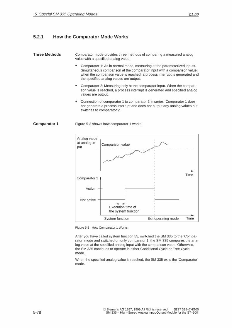
01.99
5-78 Siemens AG 1997, 1999 All Rights reserved 6ES7 335–7HG00
SM 335 – High–Speed Analog Input/Output Module for the S7–300
5.2.1 How the Comparator Mode Works
Comparator mode provides three methods of comparing a measured analogvalue with a specified analog value:
� Comparator 1: As in normal mode, measuring at the parameterized inputs.Simultaneous comparison at the comparator input with a comparison value;when the comparison value is reached, a process interrupt is generated andthe specified analog values are output.
� Comparator 2: Measuring only at the comparator input. When the compari-son value is reached, a process interrupt is generated and specified analogvalues are output.
� Connection of comparator 1 to comparator 2 in series. Comparator 1 doesnot generate a process interrupt and does not output any analog values butswitches to comparator 2.
Figure 5-3 shows how comparator 1 works:
Comparison value
Analog valueat analog in-put
Comparator 1
Active
Not active
Execution time ofthe system function
System function Exit operating mode
Time
Time
Figure 5-3 How Comparator 1 Works
After you have called system function 55, switched the SM 335 to the ‘Compa-rator’ mode and switched on only comparator 1, the SM 335 compares the ana-log value at the specified analog input with the comparison value. Otherwise,the SM 335 continues to operate in either Conditional Cycle or Free Cyclemode.
When the specified analog value is reached, the SM 335 exits the ‘Comparator’mode.
Three Methods
Comparator 1
5 Special SM 335 Operating Modes

01.99
5-79 Siemens AG 1997, 1999 All Rights reserved 6ES7 335–7HG00 SM 335 – High–Speed Analog Input/Output Module for the S7–300
Figure 5-4 shows how comparator 2 works:
Case B Case A
Comparator 2
Analog valueat the analoginput
Active
Not active
Comparison value
Execution time of the system func-tion
Systemfunction
Comparatortime expired
Comparison va-lue reached
Systemfunction
Time
Time
Figure 5-4 How Comparator 2 Works
As soon as the measured value has reached the comparison value:
� The SM 335 generates a hardware interrupt
� It outputs the specified analog values to the specified analog outputs
� It writes the number of suppressed end-of-cycle interrupts to the input valuearea (module address byte + 8)
� It exits ‘Comparator’ mode.
After exiting ‘Comparator’ mode, the SM 335 outputs the analog values speci-fied in system function 55. It continues to output these values until you forward anew analog value. The new analog value must differ in at least one bit from theone output in ‘Comparator’ mode.
The SM 335 remains in ‘Comparator’ mode until the comparison value hasbeen reached or the comparator time has expired. If the comparison value isnot reached before the comparator time expires, the SM 335 exits ‘Comparator’mode and returns to the Free Cycle or Conditional Cycle mode without modi-fying the analog outputs.
Comparator 2
Case A: Compari-son Value Reached
Case B: Compara-tor Time Expired
5 Special SM 335 Operating Modes

01.99
5-80 Siemens AG 1997, 1999 All Rights reserved 6ES7 335–7HG00
SM 335 – High–Speed Analog Input/Output Module for the S7–300
After calling the system function and switching the SM 335 to ‘Comparator’mode, when only comparator 2 is activated, the SM 335 operates as follows:
� It measures only at one analog input (as fast as possible).
� It suppresses by counts the end-of-cycle interrupts.
� It compares the measured analog value with the comparison value.
Hint: If you want to output the same analog value that was output in Comparatormode, change the least significant bit in the analog value’s binary code. Thishas no effect on the analog value, since the least significant bit is truncated, butthe SM 335 will interpret the new binary code as a new analog value.
Note
When the Comparator mode with comparator 2 is exited, the values at the SM335’s analog inputs are not current. The analog inputs are not updated until thenext measuring cycle.
Remedy: Do not read the values from the analog inputs until the next end-of-cycle interrupt has been generated.
Figure 5-5 shows how the SM 335 works when both comparators are active:
Comparison value K1
Comparison value K2
Comparator 2
Comparator 1
Not active
Active
Not active
Active
System function
Execution time of the system function Time
Time
Figure 5-5 Comparators 1 and 2 in Series
Cases A + B
Comparators 1 and 2
5 Special SM 335 Operating Modes

01.99
5-81 Siemens AG 1997, 1999 All Rights reserved 6ES7 335–7HG00 SM 335 – High–Speed Analog Input/Output Module for the S7–300
Figure 5-6 shows an application for the comparator function:
Position
Decelerate
Comparator 2
Comparator 1
Figure 5-6 Application for the Comparator Mode
A mold is closed. The closing motion must be extremely fast. The position of thetool can be acquired, for example, using a linear potentiometer. The linear po-tentiometer’s analog signal is measured by the SM 335.
When the mold closes, the SM 335 is switched to Comparator mode, with com-parators 1 and 2 connected in series.
While the mold is being closed, comparator 1 compares the measured analogvalue with the comparison value for comparator 1. This analog value is reachedwhen the form has assumed a certain position. The SM 335 now activates com-parator 2, and measures only the values at this analog input. Shortly before themold is closed, the measured analog value reaches the comparison value forcomparator 2. A hardware interrupt is generated. You can initiate deceleration inthe interrupt OB. If the whole process is to be performed even faster, specify ananalog value that the SM 335 forwards to one of its analog outputs. Use thisanalog output for direct control of the drive that moves the mold. In this way, youwill achieve fast closing and fast, repeatable deceleration.
Application
5 Special SM 335 Operating Modes

01.99
5-82 Siemens AG 1997, 1999 All Rights reserved 6ES7 335–7HG00
SM 335 – High–Speed Analog Input/Output Module for the S7–300
5.2.2 SM 335 Parameters for Comparator Mode
The parameters for the “Comparator” mode can be passed with system function55 WR_PARA.
The dynamic parameters are entered in data record 1 on the SM 335 (see Table5-2).
Table 5-2 Data Record 1 on the SM 335 for “Comparator” Mode
Byte Contents
0 Analog output value 1, high-order byte
1 Analog output value 1, low-order byte
2 Analog output value 2, high-order byte
3 Analog output value 2, low-order byte
4 Analog output value 3, high-order byte
5 Analog output value 3, low-order byte
6 Comparison value for “Comparator 1”, high-order byte
7 Comparison value for “Comparator 1”, low-order byte
8 Comparison value for “Comparator 2”, high-order byte
9 Comparison value for “Comparator 2”, low-order byte
10 Comparator time
11 Dynamic measuring cycle control
12 Comparator control byte
13 Reserved
While the comparator is active, the SM 335 can not generate a hardware inter-rupt for end-of-cycle. It is therefore possible that the SM 335 will fail to generatean end-of-cycle interrupt for a longer period of time. You can set the ComparatorTime parameter to define the amount of time the comparator may remain active.If the comparator time expires while the comparator is active, the SM 335 auto-matically returns to the Free Cycle or Conditional Cycle mode. The comparatortime is specified in milliseconds (1 = 1 ms, 2 = 2 ms, up to 0 = 256 ms).
Restrictions
Data Record 1
Comparator Time
5 Special SM 335 Operating Modes

01.99
5-83 Siemens AG 1997, 1999 All Rights reserved 6ES7 335–7HG00 SM 335 – High–Speed Analog Input/Output Module for the S7–300
The Dynamic Measuring Cycle Control byte has the following format:
= 0: Switch mode on= 1: Switch mode off
7 6 5 4 3 2 1 0
‘Comparator‘mode
Analog inputComparator 1
00 – Analog input 101 – Analog input 210 – Analog input 311 – Analog input 4
Analog inputComparator 2
00 – Analog input 101 – Analog input 210 – Analog input 311 – Analog input 4
Figure 5-7 Bits in the Dynamic Measuring Cycle Control Byte
The “Dynamic Measuring Cycle Control” byte has several functions.
� Dynamic disabling of analog inputs
� Activation of “Measuring Only” mode
� Activation of “Comparator” mode
� Comparator
The Comparator check byte provides an additional means of checking the com-parator. The Comparator check byte has the following format:
7 6 5 4 3 2 1 0
Comparator 1
Comparator 2
Direction
Hardwareinterrupt
Analog output 1
Analog output 2
Analog output 3
Analog output 4
Figure 5-8 Comparator Check Byte for “Comparator” Mode
When bit 7 in the Comparator check byte is set to “0”, the analog values arecompared in ascending order (as in Figure 5-8). If bit 7 is set to “1”, they arecompared in descending order.
When bit 4 in the Comparator check byte is set to ‘1’, the SM 335 generates ahardware interrupt at the reversing point.
Dynamic Measu-ring Cycle Control
Comparator CheckByte
Direction
Hardware Interrupt
5 Special SM 335 Operating Modes

01.99
5-84 Siemens AG 1997, 1999 All Rights reserved 6ES7 335–7HG00
SM 335 – High–Speed Analog Input/Output Module for the S7–300
Use bits 0 to 3 to specify the analog outputs to which the designated values(bytes 0 to 7 in the table) are to be forwarded.
� Bit i = ‘1’: Specified value is output
� Bit i = ‘0’: Old analog value is retained
You may set as many as three bits. The analog values are output until a newvalue is forwarded to the output.
Check bits 1 and 2 are used to activate comparators 1 and 2 (see Table 5-3).
Table 5-3 Controlling the Comparator via Check Bits 1 and 2
Bit 6 Bit 5 Comparator Performance
1 1 Activate comparators 1 and 2 in series
0 1 Activate comparator 2
1 0 Activate comparator 1
0 0 Exit Comparator mode immediately
Analog Output
Comparator 1 andComparator 2
5 Special SM 335 Operating Modes
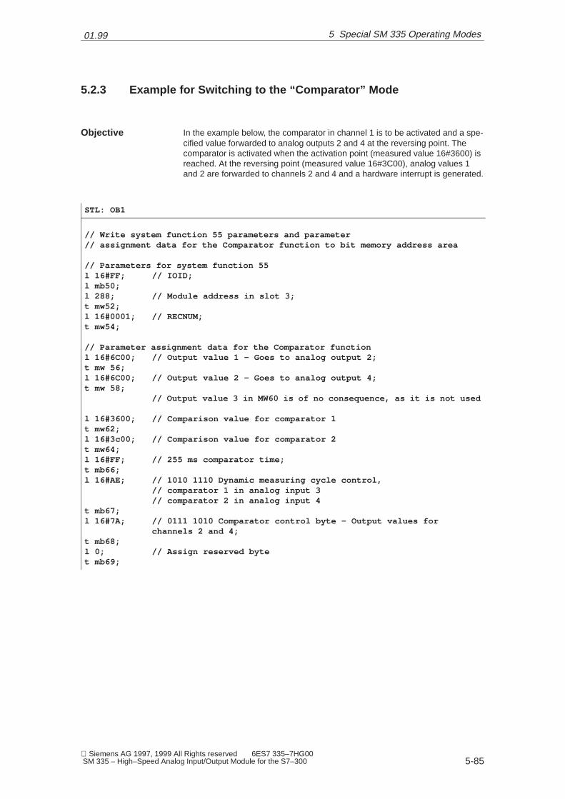
01.99
5-85 Siemens AG 1997, 1999 All Rights reserved 6ES7 335–7HG00 SM 335 – High–Speed Analog Input/Output Module for the S7–300
5.2.3 Example for Switching to the “Comparator” Mode
In the example below, the comparator in channel 1 is to be activated and a spe-cified value forwarded to analog outputs 2 and 4 at the reversing point. Thecomparator is activated when the activation point (measured value 16#3600) isreached. At the reversing point (measured value 16#3C00), analog values 1and 2 are forwarded to channels 2 and 4 and a hardware interrupt is generated.
STL: OB1
// Write system function 55 parameters and parameter// assignment data for the Comparator function to bit memory address area
// Parameters for system function 55l 16#FF; // IOID;l mb50;l 288; // Module address in slot 3;t mw52;l 16#0001; // RECNUM;t mw54;
// Parameter assignment data for the Comparator functionl 16#6C00; // Output value 1 – Goes to analog output 2;t mw 56;l 16#6C00; // Output value 2 – Goes to analog output 4;t mw 58;
// Output value 3 in MW60 is of no consequence, as it is not used
l 16#3600; // Comparison value for comparator 1t mw62;l 16#3c00; // Comparison value for comparator 2t mw64;l 16#FF; // 255 ms comparator time;t mb66;l 16#AE; // 1010 1110 Dynamic measuring cycle control,
// comparator 1 in analog input 3// comparator 2 in analog input 4
t mb67;l 16#7A; // 0111 1010 Comparator control byte – Output values for
channels 2 and 4;t mb68;l 0; // Assign reserved bytet mb69;
Objective
5 Special SM 335 Operating Modes

01.99
5-86 Siemens AG 1997, 1999 All Rights reserved 6ES7 335–7HG00
SM 335 – High–Speed Analog Input/Output Module for the S7–300
5.3 ‘Measuring Only’ Mode
In the ‘Measuring Only’ mode, the SM 335 measures only the analog inputs inthe free cycle and does not update the analog outputs. The analog outputs re-tain their old analog value for a period of 40 to 60 ms.
Note
� While the SM 335 is measuring, the watchdog is not active. This makes itimpossible to detect any internal module fault.
� A new analog value is output after the time expires.
You can use ‘Measuring Only’ mode to read values from an analog input in ra-pid succession and thus obtain, for a short time, the most current analog values(TA < 0.5 ms). After the time expires, the SM 335 returns to the previously para-meterized operating mode.
Deactivating Out-puts
Purpose
5 Special SM 335 Operating Modes

01.99
5-87 Siemens AG 1997, 1999 All Rights reserved 6ES7 335–7HG00 SM 335 – High–Speed Analog Input/Output Module for the S7–300
5.3.1 Switching to “Measuring Only” Mode
The parameters for “Measuring Only” mode can be passed to the SM 335 onlywith system function 55 WR_PARA. All parameters must be passed simulta-neously.
The SM 335’s dynamic parameters for “Measuring Only” mode are forwarded indata record 1.
You may set as many as three bits. The analog values are output until a newvalue is forwarded to the output.
Note
The parameters which you pass in data record 1 in order to switch to “Measu-ring Only” mode must be identical with the parameters you passed for FreeCycle or Conditional Cycle mode, with the exception of byte 11.
You may set as many as three bits. The analog values are output until a newvalue is forwarded to the output.
Table 5-4 The SM 335’s Data Record 1 for “Measuring Only” Mode
Byte Contents
0
1
2
3
4
5 As in Table 3-8
6
7
8
9
10
11 Dynamic measuring cycle control
12As in Table 3-8
13As in Table 3-8
Restrictions
Data Record 1
5 Special SM 335 Operating Modes
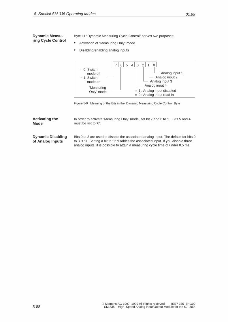
01.99
5-88 Siemens AG 1997, 1999 All Rights reserved 6ES7 335–7HG00
SM 335 – High–Speed Analog Input/Output Module for the S7–300
Byte 11 “Dynamic Measuring Cycle Control” serves two purposes:
� Activation of “Measuring Only” mode
� Disabling/enabling analog inputs
7 6 5 4 3 2 1 0
Analog input 1Analog input 2
Analog input 3Analog input 4
= ’1’: Analog input disabled= ’0’: Analog input read in
‘MeasuringOnly’ mode
= 0: Switchmode off
= 1: Switchmode on
Figure 5-9 Meaning of the Bits in the ‘Dynamic Measuring Cycle Control’ Byte
In order to activate ‘Measuring Only’ mode, set bit 7 and 6 to ‘1’. Bits 5 and 4must be set to ‘0’.
Bits 0 to 3 are used to disable the associated analog input. The default for bits 0to 3 is ‘0’. Setting a bit to ‘1’ disables the associated input. If you disable threeanalog inputs, it is possible to attain a measuring cycle time of under 0.5 ms.
Dynamic Measu-ring Cycle Control
Activating theMode
Dynamic Disablingof Analog Inputs
5 Special SM 335 Operating Modes
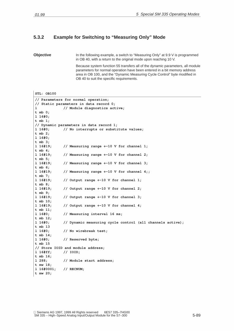
01.99
5-89 Siemens AG 1997, 1999 All Rights reserved 6ES7 335–7HG00 SM 335 – High–Speed Analog Input/Output Module for the S7–300
5.3.2 Example for Switching to “Measuring Only” Mode
In the following example, a switch to “Measuring Only” at 9.9 V is programmedin OB 40, with a return to the original mode upon reaching 10 V.
Because system function 55 transfers all of the dynamic parameters, all moduleparameters for normal operation have been entered in a bit memory addressarea in OB 100, and the “Dynamic Measuring Cycle Control” byte modified inOB 40 to suit the specific requirements.
STL: OB100
// Parameters for normal operation;// Static parameters in data record 0;l // Module diagnostics active;t mb 0;l 16#0;t mb 1;// Dynamic parameters in data record 1;l 16#0; // No interrupts or substitute values;t mb 2;l 16#0;t mb 3;l 16#19; // Measuring range +–10 V for channel 1;t mb 4;l 16#19; // Measuring range +–10 V for channel 2;t mb 5;l 16#19; // Measuring range +–10 V for channel 3;t mb 6;l 16#19; // Measuring range +–10 V for channel 4;;t mb 7;l 16#19; // Output range +–10 V for channel 1;t mb 8;l 16#19; // Output range +–10 V for channel 2;t mb 9;l 16#19; // Output range +–10 V for channel 3;t mb 10;l 16#19; // Output range +–10 V for channel 4;t mb 11;l 16#0; // Measuring interval 16 ms;t mb 12;l 16#0; // Dynamic measuring cycle control (all channels active);t mb 13l 16#0; // No wirebreak test;t mb 14;l 16#0; // Reserved byte;t mb 15// Store IOID and module address;l 16#ff; // IOID;t mb 16;l 288; // Module start address;t mw 18;l 16#0001; // RECNUM;t mw 20;
Objective
5 Special SM 335 Operating Modes

01.99
5-90 Siemens AG 1997, 1999 All Rights reserved 6ES7 335–7HG00
SM 335 – High–Speed Analog Input/Output Module for the S7–300
STL OB 40
l piw 288;l 16#6940;<I; // Input voltage <=9.9 volts ?jc END;
// // Beginning with 9.9 V, only this input will be measured;// // until the input voltage has reached 10.0 V;l 16#ce // 1100 1110 – Activate “Measuring Only”, disable channels 2–4;t mb 12;call sfc 55 ( // Transfer dynamic parameters in data record 1;
IOID := mb 16,LADDR := mw 18,RECNUM := mw 20,RECORD .= P#m2.0 byte 14,RET_VAL :=mw 100);
AEK1:l piw 288; ;Read measuring channel 1;l 16#6c00;>=I; ;10.0 V reached ?jc MAUS;
// 10 V not reached, program a response, if any
ju AEK1; ;Return for repeated reading of measuring channel 1;
MAUS:// 10 V reached, return to original model 16#40; // 0100 0000 – Deactivate “Measuring Only” mode, measure allchannels;t mb 12;call sfc 55 ( // Transfer dynamic parameters in data record 1;
IOID := mb 16,LADDR := mw 18,RECNUM := mw 20,RECORD .= P#m2.0 byte 14,RET_VAL :=mw 100);
END:END_ORGANISATION_BLOCK
�
5 Special SM 335 Operating Modes

6-91 Siemens AG 1997, 1999 All Rights reserved 6ES7 335–7HG00 SM 335 – High–Speed Analog Input/Output Module for the S7–300
Detecting and Correcting Faults
The SM 335 can detect faults at inputs and outputs. You can respond to thefaults according to the methods of the S7-300.
We deal with the following topics in this chapter:
Topic Section
Principle of diagnostics 6.1
Setting diagnostics with S7 Configuration 6.2
Evaluating diagnostics data in OB 82 6.3
SM 335 error tree 6.4
Remedies for faults 6.5
Principle
In this Chapter
6
01.99
6-92 Siemens AG 1997, 1999 All Rights reserved 6ES7 335–7HG00
SM 335 – High–Speed Analog Input/Output Module for the S7–300
6.1 Principle of Diagnostics
When an error or fault occurs on an SM 335, the SF LED on both the CPU andthe SM 335 goes on.
An entry is made in the CPU’s diagnostic backup when SM 335 diagnosticshave been enabled. If you have enabled diagnostic interrupts, the SM 335 ge-nerates one. When a diagnostic interrupt is generated, the diagnostic OB (OB82) is invoked in the CPU. Refer to Section 3.2.2 for information on how to initia-lize the SM 335 using the S7 Configuration application.
You can also enable diagnostics when the parameters are passed with systemfunction WR_PARA. Descriptions of the SM 335 parameters can be found inSection 3.3.2.
You can read out the contents of the diagnostic backup with the S7 Info tool.
If you have enabled diagnostic interrupts, the SM 335 generates one. When adiagnostic interrupt is generated, the diagnostic OB (OB 82) is invoked in theCPU. You can program your response to the error/fault which caused the inter-rupt in this OB. Refer to Section 6.3 for an example of how to read out the dia-gnostic data in OB 82.
The SM 335’s diagnostic data can be read with system function 59. See Section3.4.2 for information on the formats of these data.
OB 82 is invoked automatically when diagnostic interrupts are enabled, andmakes the module start address available as part of the local data.
The program is interrupted when OB 82 is invoked. If the program containstime-critical sequences, the scan time needed for OB 82 may increase the re-sponse time. One way of preventing this is to save only the module start ad-dress in OB 82 and evaluate the diagnostic data in OB 1.
LEDs
Diagnostics Para-meters
Diagnostic Backup
Diagnostic OB 82
Diagnostic DataFormat
Advantages of aDiagnostic Inter-rupt
Disadvantages of aDiagnostic Inter-rupt
6 Detecting and Correcting Faults
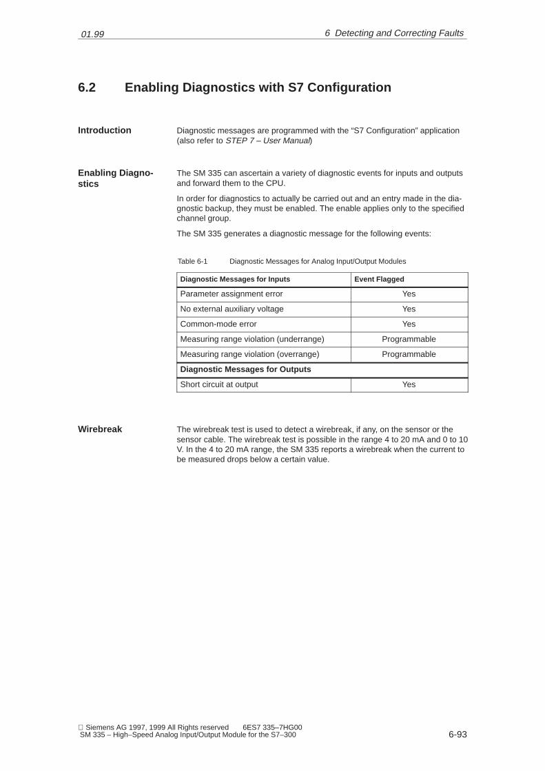
01.99
6-93 Siemens AG 1997, 1999 All Rights reserved 6ES7 335–7HG00 SM 335 – High–Speed Analog Input/Output Module for the S7–300
6.2 Enabling Diagnostics with S7 Configuration
Diagnostic messages are programmed with the “S7 Configuration” application(also refer to STEP 7 – User Manual)
The SM 335 can ascertain a variety of diagnostic events for inputs and outputsand forward them to the CPU.
In order for diagnostics to actually be carried out and an entry made in the dia-gnostic backup, they must be enabled. The enable applies only to the specifiedchannel group.
The SM 335 generates a diagnostic message for the following events:
Table 6-1 Diagnostic Messages for Analog Input/Output Modules
Diagnostic Messages for Inputs Event Flagged
Parameter assignment error Yes
No external auxiliary voltage Yes
Common-mode error Yes
Measuring range violation (underrange) Programmable
Measuring range violation (overrange) Programmable
Diagnostic Messages for Outputs
Short circuit at output Yes
The wirebreak test is used to detect a wirebreak, if any, on the sensor or thesensor cable. The wirebreak test is possible in the range 4 to 20 mA and 0 to 10V. In the 4 to 20 mA range, the SM 335 reports a wirebreak when the current tobe measured drops below a certain value.
Introduction
Enabling Diagno-stics
Wirebreak
6 Detecting and Correcting Faults

01.99
6-94 Siemens AG 1997, 1999 All Rights reserved 6ES7 335–7HG00
SM 335 – High–Speed Analog Input/Output Module for the S7–300
In the input range of 0 to 10 V, the wirebreak test differs in that it is executedafter completion of AD conversion of the active analog inputs. The test is execu-ted by outputting brief current pulses of approximately 30 µA to the relevantinput. The SM 335 can detect a wirebreak by analyzing the resulting voltagedifference.
In order to ensure that this form of wirebreak test will function properly, the capa-city of the connecting cable and the sensors must not exceed 10 nF. In general,cables of up to 30 m in length are no problem. The source resistance must notexceed 2.5 Kohms, as otherwise a wirebreak might be reported erroneously.
Because the SM 335’s wirebreak test takes some time, it can be activated anddeactivated as needed.
If you have enabled diagnostics, you may also specify whether you want tohave a diagnostic interrupt generated when a diagnostic event occurs. Whenthe SM 335 generates a diagnostic interrupt, the CPU calls OB 82.
Measuring Range0 to 10 V
Diagnostic Inter-rupt Enable
6 Detecting and Correcting Faults
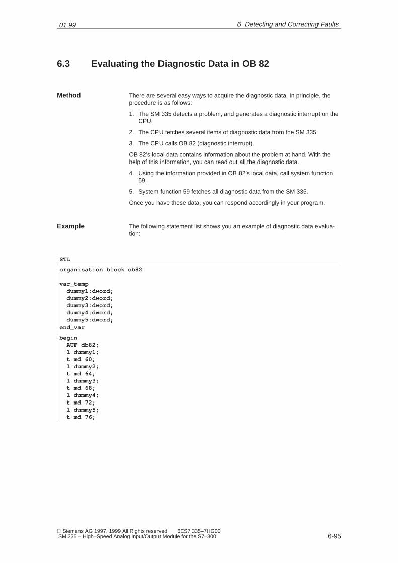
01.99
6-95 Siemens AG 1997, 1999 All Rights reserved 6ES7 335–7HG00 SM 335 – High–Speed Analog Input/Output Module for the S7–300
6.3 Evaluating the Diagnostic Data in OB 82
There are several easy ways to acquire the diagnostic data. In principle, theprocedure is as follows:
1. The SM 335 detects a problem, and generates a diagnostic interrupt on theCPU.
2. The CPU fetches several items of diagnostic data from the SM 335.
3. The CPU calls OB 82 (diagnostic interrupt).
OB 82’s local data contains information about the problem at hand. With thehelp of this information, you can read out all the diagnostic data.
4. Using the information provided in OB 82’s local data, call system function59.
5. System function 59 fetches all diagnostic data from the SM 335.
Once you have these data, you can respond accordingly in your program.
The following statement list shows you an example of diagnostic data evalua-tion:
STL
organisation_block ob82
var_temp dummy1:dword; dummy2:dword; dummy3:dword; dummy4:dword; dummy5:dword;end_var
begin AUF db82; l dummy1; t md 60; l dummy2; t md 64; l dummy3; t md 68; l dummy4; t md 72; l dummy5; t md 76;
Method
Example
6 Detecting and Correcting Faults

01.99
6-96 Siemens AG 1997, 1999 All Rights reserved 6ES7 335–7HG00
SM 335 – High–Speed Analog Input/Output Module for the S7–300
// Stipulate data for system function 59 l 16#54; // IOID t mb 52;
l dbw 6; // Module start address is in DBW 6 t mw 54;
l 1; t mb 56; // RECNUM = 1, that is, fetch parameter data record 1
l 0; t mw 58; // Reset to 0 before calling system function RET_VAL r m 50.1; // Reset BUSY bit prior to system function call
// Call system function
call sfc 59( REQ := m 50.0; IOID := mb 52; LADDR := mw 54; RECNUM := mw 56; RET_VAL := mw 58; BUSY := m 50.1; RECORD := p#m80.0byte16 );
// Local data are in MB 60 to MB 79// Diagnostic data for the module are in MB 80 to MB 85
end_organization_block
6 Detecting and Correcting Faults

01.99
6-97 Siemens AG 1997, 1999 All Rights reserved 6ES7 335–7HG00 SM 335 – High–Speed Analog Input/Output Module for the S7–300
6.4 SM 335 Error Tree
Read the SM 335 error tree as follows: Bit 0 of module diagnostic byte 1 indica-tes whether an error has occurred.
1. Check to see whether bit 0 in module diagnostic byte 1 is set.
2. If it is, check the bits to which the arrows going out from bit 0 of module dia-gnostic byte 1 point.
3. If a bit is set, follow the arrows going out from that bit and see which of thosebits are set, and so on.
4. Refer to Table 6-2 for a description of the error associated with each bit.
Module diagnostic byte 1, bit 0
Module diagnostic byte 1, bit 1
Module diagnosticbyte 1, bit 7
Module diagnosticbyte 3, bit 3
Module diagnosticbyte 4, bit 2
Module diagnosticbyte 4, bit 4
Module diagnosticbyte 1, bit 2
Module diagnosticbyte 1, bit 6 Channel-specific dia-
gnostic byte for analogoutput bit 0
Channel-specific diagnosticbyte for analog input bit 0
Module diagnostic byte 1, bit 3
Module diagnostic byte 3, bit 0Module diagnostic byte 1, bit 4
Channel-specific diagnosticbyte for analog input bit 1
Channel-specific diagnosticbyte for analog input bit 4
Channel-specific diagnosticbyte for analog input bit 6
Channel-specific diagnosticbyte for analog input bit 7
Channel-specific diagnosticbyte for analog output bit 2
Figure 6-1 SM 335 Error Tree
Tips for Readers
6 Detecting and Correcting Faults
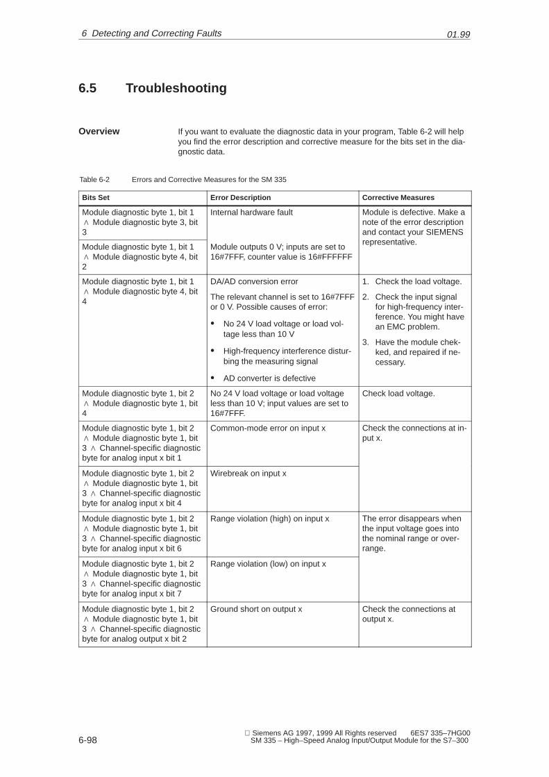
01.99
6-98 Siemens AG 1997, 1999 All Rights reserved 6ES7 335–7HG00
SM 335 – High–Speed Analog Input/Output Module for the S7–300
6.5 Troubleshooting
If you want to evaluate the diagnostic data in your program, Table 6-2 will helpyou find the error description and corrective measure for the bits set in the dia-gnostic data.
Table 6-2 Errors and Corrective Measures for the SM 335
Bits Set Error Description Corrective Measures
Module diagnostic byte 1, bit 1� Module diagnostic byte 3, bit3
Internal hardware fault Module is defective. Make anote of the error descriptionand contact your SIEMENS
t tiModule diagnostic byte 1, bit 1� Module diagnostic byte 4, bit2
Module outputs 0 V; inputs are set to16#7FFF, counter value is 16#FFFFFF
representative.
Module diagnostic byte 1, bit 1� Module diagnostic byte 4, bit4
DA/AD conversion error
The relevant channel is set to 16#7FFFor 0 V. Possible causes of error:
� No 24 V load voltage or load vol-tage less than 10 V
� High-frequency interference distur-bing the measuring signal
� AD converter is defective
1. Check the load voltage.
2. Check the input signalfor high-frequency inter-ference. You might havean EMC problem.
3. Have the module chek-ked, and repaired if ne-cessary.
Module diagnostic byte 1, bit 2� Module diagnostic byte 1, bit4
No 24 V load voltage or load voltageless than 10 V; input values are set to16#7FFF.
Check load voltage.
Module diagnostic byte 1, bit 2� Module diagnostic byte 1, bit3 � Channel-specific diagnosticbyte for analog input x bit 1
Common-mode error on input x Check the connections at in-put x.
Module diagnostic byte 1, bit 2� Module diagnostic byte 1, bit3 � Channel-specific diagnosticbyte for analog input x bit 4
Wirebreak on input x
Module diagnostic byte 1, bit 2� Module diagnostic byte 1, bit3 � Channel-specific diagnosticbyte for analog input x bit 6
Range violation (high) on input x The error disappears whenthe input voltage goes intothe nominal range or over-range.
Module diagnostic byte 1, bit 2� Module diagnostic byte 1, bit3 � Channel-specific diagnosticbyte for analog input x bit 7
Range violation (low) on input x
Module diagnostic byte 1, bit 2� Module diagnostic byte 1, bit3 � Channel-specific diagnosticbyte for analog output x bit 2
Ground short on output x Check the connections atoutput x.
Overview
6 Detecting and Correcting Faults

01.99
6-99 Siemens AG 1997, 1999 All Rights reserved 6ES7 335–7HG00 SM 335 – High–Speed Analog Input/Output Module for the S7–300
Table 6-2 Errors and Corrective Measures for the SM 335, continued
Bits Set Corrective MeasuresError Description
Module diagnostic byte 1, bit 1� Module diagnostic byte 3, bit0
Coding plug improperly inserted/not in-serted.
Check to make sure that thecoding plug has been inser-ted correctly, and that thecoding plug setting con-forms with the parameters.
Module diagnostic byte 1, bit 7� Module diagnostic byte 1, bit6
(Module diagnostic byte 1,Bit 0 = ‘0’ !)
Module not initialized.
The SM 335 is using default parame-ters (no hardware interrupts, no dia-gnostic interrupts).
Initialize the SM 335.
Module diagnostic byte 1, bit 2�
Channel-specific diagnostic bytefor analog output x, bit 0Channel-specific diagnostic bytefor analog input x, bit 0
Invalid parameters in channel x.
When it detects an invalid channel-spe-cific parameter, the SM 335 flags thechannel for which the parameter wasspecified.
Initialize the SM 335 cor-rectly.
�
6 Detecting and Correcting Faults
01.99
6-100 Siemens AG 1997, 1999 All Rights reserved 6ES7 335–7HG00
SM 335 – High–Speed Analog Input/Output Module for the S7–300
6 Detecting and Correcting Faults

7-101 Siemens AG 1997, 1999 All Rights reserved 6ES7 335–7HG00 SM 335 – High–Speed Analog Input/Output Module for the S7–300
Program Examples for the SM 335
In this chapter, we intend to record some program examples with which you canget optimum use out of your SM 335.
The current version of the manual contains only one program. If you can sug-gest further programs for the SM 335 for recording here, please send the Sug-gestions and Corrections form to us and specify your address. Your program willthen possibly appear in the next edition of the manual.
Purpose
Suggestions?
7
01.99
7-102 Siemens AG 1997, 1999 All Rights reserved 6ES7 335–7HG00
SM 335 – High–Speed Analog Input/Output Module for the S7–300
7.1 An Example of Reparameterizing the SM 335
In the example below, we switch the measuring range � 10 V in channel 2 tothe measuring range � 2.5 V at a measured value of 2 volts and we switch tothe measuring range � 10 V at a measured value � 2.5 V.
Since system function 55 transfers all the dynamic parameters, we store all theparameters of our module for normal mode in a bit memory area of OB 100, forexample, at startup, and we modify the measuring range parameters in OB 1 inaccordance with the input voltage.
Objective
7 Progarm Examples for the SM 335
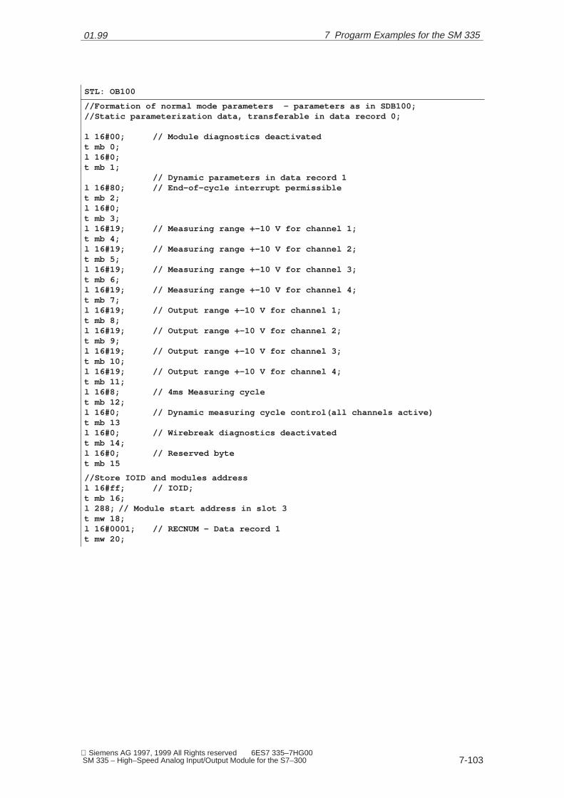
01.99
7-103 Siemens AG 1997, 1999 All Rights reserved 6ES7 335–7HG00 SM 335 – High–Speed Analog Input/Output Module for the S7–300
STL: OB100
//Formation of normal mode parameters – parameters as in SDB100;//Static parameterization data, transferable in data record 0;
l 16#00; // Module diagnostics deactivatedt mb 0;l 16#0;t mb 1;
// Dynamic parameters in data record 1l 16#80; // End-of-cycle interrupt permissiblet mb 2;l 16#0;t mb 3;l 16#19; // Measuring range +–10 V for channel 1;t mb 4;l 16#19; // Measuring range +–10 V for channel 2;t mb 5;l 16#19; // Measuring range +–10 V for channel 3;t mb 6;l 16#19; // Measuring range +–10 V for channel 4;t mb 7;l 16#19; // Output range +–10 V for channel 1;t mb 8;l 16#19; // Output range +–10 V for channel 2;t mb 9;l 16#19; // Output range +–10 V for channel 3;t mb 10;l 16#19; // Output range +–10 V for channel 4;t mb 11;l 16#8; // 4ms Measuring cyclet mb 12;l 16#0; // Dynamic measuring cycle control(all channels active)t mb 13l 16#0; // Wirebreak diagnostics deactivatedt mb 14;l 16#0; // Reserved bytet mb 15
//Store IOID and modules addressl 16#ff; // IOID;t mb 16;l 288; // Module start address in slot 3t mw 18;l 16#0001; // RECNUM – Data record 1t mw 20;
7 Progarm Examples for the SM 335

01.99
7-104 Siemens AG 1997, 1999 All Rights reserved 6ES7 335–7HG00
SM 335 – High–Speed Analog Input/Output Module for the S7–300
STL: OB1
l mb 5;l 16#;==I;spb E25V
//Measuring range +/–10 V set: Measured value <2volts ?l pew 288;l 16#1d80;>I; //Change measuring range > 2 volts ?spb C10V;
//Measuring range +–10 volts to +–2,5 volts;l #15 //Measuring range +–2,5 volts in channnel 2;t mb 5;call sfc 55 ( //Transfer dynamic parameters of data record 1;
IOID := mb 16,LADDR := mw 18,RECNUM := mw 20,RECORD .= P#m2.0 byte 14,RET_VAL :=mw 100);
spa E25V;
C10V: ...spa END;
//Measuring range +–2,5 V set: Measured value >2,5 volts ?E25V: l pew 288;
l 16#6c00<I; //Input voltage < 2,5 volts ?spb C25V;
//Change measuring range +/–2,5 volts to +/–10 volts;l #19 //Measuring range +/–10 volts in channnel 2;t mb 5;call sfc 55 ( //Transfer dynamic parameters of data record 1;
IOID := mb 16,LADDR := mw 18,RECNUM := mw 20,RECORD .= P#m2.0 byte 14,RET_VAL :=mw 100);
C25V: ...spa ENDE;
�
7 Progarm Examples for the SM 335

A
A-105 Siemens AG 1997, 1999 All Rights reserved 6ES7 335–7HG00 SM 335 – High–Speed Analog Input/Output Module for the S7–300
Index
Zahlen
24 V supply voltage, 2-33
A
ADC/DAC error, 3-63Analog inputs
connecting, 2-25technical specifications, 1-17
Analog outputs, connecting, 2-27
B
Basic settings for input, parameter, 3-43
C
Common mode error, 3-64Comparator. Siehe Comparator modeComparator 2, 5-79Comparator check byte, 5-83Comparator mode, 5-77
example, 5-85principle, 5-78
Comparator 1, 5-78Comparator-check byte, 3-52Conditional cycle
see Operating mode, conditional cycleparameter for, 3-47
Connecting the SM 335, basic rules, 2-24Cycle time, for A/D conversion, 3-43
D
Default settings, 3-42Diagnostic interrupt enable, 3-43Diagnostics for inputs, parameter, 3-43Diagnostics for output, parameter, 3-43Diagnostig data, format, 3-58
E
EEPROM error, 3-63End-of-cycle interrupt enable, 3-43End-of-cycle interrupt, 1-22
F
Free cyclesee Operating mode, free cycleparameter for, 3-47
I
Interference suppressor filter, 2-33Interval counter
determining speed, 4-74technical specifications, 1-19
Interval counter inputconnecting, 2-29counter values, 4-73parameterizing, 4-72principles of measuring, 4-69wiring, 4-70
M
Measurement, parameter, 3-43Measuring only mode, 5-86
example, 5-89principle, 5-86switching to, 5-87
Measuring range module, 1-15Measuring range violation: overrange, 3-43Measuring range violation: underrange, 3-43
N
Number of pulses, 4-69
O
Operating modeconditional cycle, 1-22free cycle, 1-21
Outputparameter, 3-43technical specifications, 1-18values, 3-40
A
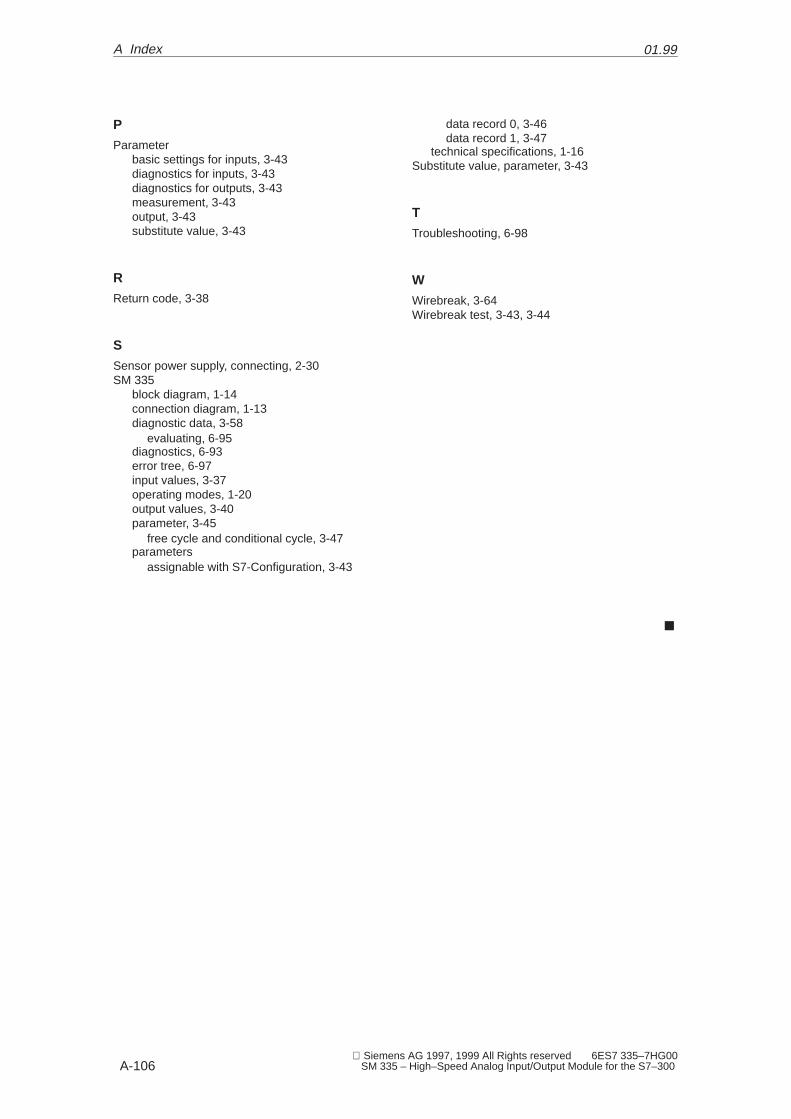
A
01.99
A-106 Siemens AG 1997, 1999 All Rights reserved 6ES7 335–7HG00
SM 335 – High–Speed Analog Input/Output Module for the S7–300
P
Parameterbasic settings for inputs, 3-43diagnostics for inputs, 3-43diagnostics for outputs, 3-43measurement, 3-43output, 3-43substitute value, 3-43
R
Return code, 3-38
S
Sensor power supply, connecting, 2-30SM 335
block diagram, 1-14connection diagram, 1-13diagnostic data, 3-58
evaluating, 6-95diagnostics, 6-93error tree, 6-97input values, 3-37operating modes, 1-20output values, 3-40parameter, 3-45
free cycle and conditional cycle, 3-47parameters
assignable with S7-Configuration, 3-43
data record 0, 3-46data record 1, 3-47
technical specifications, 1-16Substitute value, parameter, 3-43
T
Troubleshooting, 6-98
W
Wirebreak, 3-64Wirebreak test, 3-43, 3-44
�
A Index

From
Name
Company/Dept.
Address
Telephone: /
Suggestions
Corrections
For Publication/Manual:
System SolutionsSM 335 – High–Speed Analog Input/Output Module for the SIMATIC S7–300
Manual
Order No.: 6ES7 335–7HG00–8BA1Edition: 01.99
Should you come across any printing er-rors when reading this publication,please notify us on this sheet. Suggesti-ons for improvement are also welcome.
SIEMENS AG
A&D MC ISP.O. Box 3180
D–91050 ErlangenFederal Republic of Germany(Fax +49–9131/98–1145)
Telefax: /
Suggestions and/or corrections

Bestell–Nr.: 6ES7 335–7HG00–8BA1Printed in the Federal Republic of GermanySiemens Aktiengesellschaft
Siemens AG 1997–1999 All Rights ReservedÄnderungen vorbehalten
Herausgegeben von Siemens AGBereich AutomatisierungstechnikGeschäftsgebiet Automatisierungssystemefür Werkzeugmaschinen, Roboterund SondermaschinenPostfach 3180, D–91050 Erlangen
� �� ���
����������������
Der Inhalt dieser Dokumentation wurde auf umwelt-freundlichem, chlorfrei gebleichtem Papier gedruckt.