sm24tat2sa - transition networks · ch apter 15 dms (device management system) ... this manual is...
TRANSCRIPT

Transition Networks SMxTAT2SA Web User Guide
33717 Rev. A https://www.transition.com Page 1 of 241
SM8TAT2SA, SM16TAT2SA, and
SM24TAT2SA
Smart Managed Switches, 8-/16-/24-Port
Gigabit PoE+, 2-Port 100/1000 SFP
Web User Guide 33717 Rev. A

Transition Networks SMxTAT2SA Web User Guide
33717 Rev. A https://www.transition.com Page 2 of 241
Trademarks
All trademarks and registered trademarks are the property of their respective owners.
Copyright Notice/Restrictions
Copyright © 2017 Transition Networks. All rights reserved. No part of this work may be reproduced
or used in any form or by any means (graphic, electronic or mechanical) without written permission
from Transition Networks. Printed in the U.S.A.
SMxTAT2SA Smart Managed Switches Web User Guide 33717 Rev. A
Contact Information Transition Networks 10900 Red Circle Drive Minnetonka, MN 55343 USA tel: +1.952.941.7600 | toll free: 1.800.526.9267 | fax: 952.941.2322 [email protected] | [email protected] | [email protected]
Revision History
Rev Date Description
A 3/8/17 Initial release for SMxTAT2SA at v1.00.

Transition Networks SMxTAT2SA Web User Guide
33717 Rev. A https://www.transition.com Page 3 of 241
Table of Contents
INTRODUCTION ........................................................................................................................................... 6
CHAPTER 1 OPERATION OF WEB-BASED MANAGEMENT ............................................................ 8
CHAPTER 2 FIRST TIME WIZARD .................................................................................................... 10
CHAPTER 3 SYSTEM .......................................................................................................................... 13
3-1 SYSTEM INFORMATION ................................................................................................................................. 13 3-2 IP ADDRESS ................................................................................................................................................ 15
3-2.1 IP Settings ......................................................................................................................................... 15 3-2.1 Advanced IP Settings ....................................................................................................................... 16 3-2.2 IP Status ............................................................................................................................................ 18
3-3 SYSTEM TIME ............................................................................................................................................... 20 3-4 SYSTEM LOG ................................................................................................................................................ 23
3-4.1 Syslog Configuration ....................................................................................................................... 23 3-4.2 View Log ........................................................................................................................................... 24
3-5 LLDP .......................................................................................................................................................... 26 3-5.1 LLDP Configuration ......................................................................................................................... 26 3-5.2 LLDP-MED Configuration ............................................................................................................... 29 3-5.3 LLDP Neighbor ................................................................................................................................. 34 3-5.4 LLDP-MED Neighbor ....................................................................................................................... 36 3-5.5 LLDP Statistics .................................................................................................................................. 40
3-6 UPNP ......................................................................................................................................................... 42
CHAPTER 4 PORT MANAGEMENT .................................................................................................. 43
4-1 PORT CONFIGURATION ................................................................................................................................. 43 4-2 PORT STATISTICS .......................................................................................................................................... 45 4-3 SFP PORT INFO ........................................................................................................................................... 48 4-4 ENERGY EFFICIENT ETHERNET ....................................................................................................................... 50 4-5 LINK AGGREGATION ..................................................................................................................................... 51
4-5.1 Port ................................................................................................................................................... 51 4-5.2 Aggregator View .............................................................................................................................. 53 4-5.3 Aggregation Hash Mode ................................................................................................................. 55 4-5.4 LACP System Priority ....................................................................................................................... 56
4-6 LOOP PROTECTION ...................................................................................................................................... 57 4-6.1 Configuration ................................................................................................................................... 57 4-6.2 Status ................................................................................................................................................ 59
CHAPTER 5 POE MANAGEMENT ..................................................................................................... 60
5-1 POE CONFIGURATION .................................................................................................................................. 60 5-2 POE STATUS ................................................................................................................................................ 62 5-3 POE POWER DELAY ..................................................................................................................................... 64 5-4 POE AUTO POWER RESET ............................................................................................................................. 65 5-5 POE SCHEDULING PROFILE ........................................................................................................................... 67
CHAPTER 6 VLAN MANAGEMENT .................................................................................................. 68
6-1 VLAN CONFIGURATION ............................................................................................................................... 68 6-2 VLAN MEMBERSHIP .................................................................................................................................... 71 6-3 VLAN PORT STATUS .................................................................................................................................... 73 6-4 VLAN SELECTIVE QINQ ................................................................................................................................... 75 6-5 MAC-BASED VLAN ........................................................................................................................................ 76 6-6 PROTOCOL-BASED VLAN .................................................................................................................................. 78 6-7 IP SUBNET-BASED VLAN.................................................................................................................................. 80 6-8 PRIVATE VLAN ............................................................................................................................................ 81 6-9 PORT ISOLATION .......................................................................................................................................... 82

Transition Networks SMxTAT2SA Web User Guide
33717 Rev. A https://www.transition.com Page 4 of 241
6-10 VOICE VLAN ............................................................................................................................................ 83
CHAPTER 7 QUALITY OF SERVICE ................................................................................................... 86
7-1 GLOBAL SETTINGS........................................................................................................................................ 86 7-2 PORT SETTINGS ........................................................................................................................................... 87 7-3 PORT POLICING ........................................................................................................................................... 89 7-4 PORT SHAPER .............................................................................................................................................. 90 7-5 STORM CONTROL ........................................................................................................................................ 92 7-6 PORT SCHEDULER ........................................................................................................................................ 93 7-7 COS/802.1P MAPPING ............................................................................................................................... 94 7-8 COS/802.1P REMARKING ............................................................................................................................ 95 7-9 IP PRECEDENCE MAPPING ............................................................................................................................ 96 7-10 IP PRECEDENCE REMARKING ...................................................................................................................... 97 7-11 DSCP MAPPING ....................................................................................................................................... 98 7-12 DSCP REMARKING .................................................................................................................................... 99
CHAPTER 8 SPANNING TREE ......................................................................................................... 100
8-1 STATE ........................................................................................................................................................ 101 8-2 REGION CONFIG ........................................................................................................................................ 102 8-3 INSTANCE VIEW ......................................................................................................................................... 103
CHAPTER 9 MAC ADDRESS TABLES .............................................................................................. 109
9-1 CONFIGURATION........................................................................................................................................ 109 9-2 INFORMATION ........................................................................................................................................... 111
CHAPTER 10 MULTICAST ................................................................................................................ 112
10-1 IGMP SNOOPING ................................................................................................................................... 112 10-1.1 Basic Configuration ..................................................................................................................... 112 10-1.2 VLAN Configuration .................................................................................................................... 114 10-1.3 Status ............................................................................................................................................ 116 10-1.4 Group Information ...................................................................................................................... 118 10-1.5 IGMP SFM Information ............................................................................................................... 119
10-2 MLD SNOOPING ..................................................................................................................................... 121 10-2.1 Basic Configuration ..................................................................................................................... 121 10-2.2 VLAN Configuration .................................................................................................................... 123 10-2.3 Status ............................................................................................................................................ 125 10-2.4 Groups Information ..................................................................................................................... 126 10-2.5 MLD SFM Information ................................................................................................................. 127
CHAPTER 11 DHCP .......................................................................................................................... 135
11-1 SNOOPING .............................................................................................................................................. 135 11-1.1 Configuration ............................................................................................................................... 135 11-1.2 Snooping Table ............................................................................................................................ 137
CHAPTER 12 SECURITY ................................................................................................................... 144
12-1 MANAGEMENT ........................................................................................................................................ 144 12-1.1 Account ......................................................................................................................................... 144 12-1.2 Privilege Level .............................................................................................................................. 146 12-1.3 Auth Method ................................................................................................................................ 147 12-1.4 Access Management .................................................................................................................... 149
12-2 IEEE 802.1X ........................................................................................................................................... 151 12-2.1 Configuration ............................................................................................................................... 151 12-2.2 Status ............................................................................................................................................ 155
12-3 PORT SECURITY ....................................................................................................................................... 157 12-3.1 Configuration ............................................................................................................................... 157 12-3.2 Status ............................................................................................................................................ 159
12-4 RADIUS ................................................................................................................................................. 173

Transition Networks SMxTAT2SA Web User Guide
33717 Rev. A https://www.transition.com Page 5 of 241
12-4.1 Configuration ............................................................................................................................... 173 12-4.2 Status ............................................................................................................................................ 175
12.5 RMON CONFIGURATION .............................................................................................................................. 179 12.6 TACACS+ CONFIGURATION .......................................................................................................................... 186 12.7 ACCESS CONTROL LIST .................................................................................................................................. 187 12.8 EVENT NOTIFICATION ................................................................................................................................... 196
CHAPTER 13 DIAGNOSTICS ........................................................................................................... 198
13-1 PING ....................................................................................................................................................... 198 13-2 CABLE DIAGNOSTICS ................................................................................................................................ 200 13-3 TRACEROUTE ........................................................................................................................................... 202 13-4 MIRRORING ............................................................................................................................................ 203
CHAPTER 14 MAINTENANCE ......................................................................................................... 205
14-1 CONFIGURATION ..................................................................................................................................... 205 14-1.1 Save startup-config ..................................................................................................................... 205 14-1.2 Backup Configuration ................................................................................................................. 206 14-1.3 Restore Configuration ................................................................................................................. 207 14-1.4 Activate config ............................................................................................................................. 208 14-1.5 Delete config ................................................................................................................................ 209
14-2 RESTART DEVICE ...................................................................................................................................... 210 14-3 FACTORY DEFAULTS .................................................................................................................................. 211 14-4 FIRMWARE .............................................................................................................................................. 212
14-4.1 Firmware Upgrade ...................................................................................................................... 212 14-4.1 Firmware Selection ...................................................................................................................... 214
CHAPTER 15 DMS (DEVICE MANAGEMENT SYSTEM) ............................................................... 215
APPENDIX A TROUBLESHOOTING, WARRANTY, SUPPORT AND COMPLIANCE ................... 227
GLOSSARY OF TERMS .............................................................................................................................. 230

33717 Rev. A https://www.transition.com Page 6 of 241
INTRODUCTION
Overview This manual describes how to configure and monitor the SMxTAT2SA via the web via its RJ-45 serial interface and Ethernet ports. The SMxTAT2SA Smart Managed GbE PoE+ switch is the next-generation Ethernet switch offering powerful L2 features with better functionality and usability. It delivers cost-effective business and transport Ethernet services via fiber or copper connections.
The SMxTAT2SA delivers 8/16/24 (10M/100M/1G) RJ45 ports with 8 PoE+ ports (supports 802.3 at/af, and total up to 130W on the SM8TAT2SA) and 2 GbE SFP ports. SMxTAT2SA provides high hardware performance and environment flexibility for SMBs and Enterprises. The embedded Device Managed System (DMS) feature makes the switch easy to use, configure, install, and troubleshoot in video surveillance, wireless access, and other SMB and Enterprise applications.
SMxTAT2SA features include:
L2+ features for better manageability, security, QoS, and performance IPv4/IPv6 dual stack management SSH/SSL secured management SNMP v1/v2c/v3 RMON groups 1,2,3,9 IGMP v1/v2/v3 Snooping and MLD v1/v2 Snooping RADIUS and TACACS+ authentication IP Source Guard DHCP Snooping, DHCP Relay (Option 82), DHCP statistics 802.1d (STP), 802.1w (RSTP) and 802.1s (MSTP) LACP and static link aggregation Q-in-Q double tag VLAN GVRP dynamic VLAN
Overview of this Manual
Chapter 1 - Operation of Web-based Management Chapter 2 - First Time Wizard Chapter 3 - System Chapter 4 - Port Management Chapter 5 - PoE Management Chapter 6 - VLAN Management Chapter 7 - Quality of Service Chapter 8 - Spanning tree Chapter 9 - MAC Address Tables Chapter 10 - Multicast Chapter 11 - DHCP Chapter 12 - Security Chapter 13 - Diagnostics Chapter 14 - Maintenance Chapter 15 - DMS (Device Management System)

Transition Networks SMxTAT2SA Web User Guide
33717 Rev. A https://www.transition.com Page 7 of 241
Models
This manual documents three similar models as described below. The models differ mainly in port count. Model differences are noted where applicable throughout this manual.
SM8TAT2SA PoE+ layer 2 Smart Managed Switch with Web GUI, SNMP management; PoE scheduling, APR, and DMS feature support. Port support description: (8) 10/100/1000Base-T PoE+ ports with 2 SFP ports
SM16TAT2SA PoE+ layer 2 Smart Managed Switch with Web GUI, SNMP management; PoE scheduling, APR, and DMS feature support. Port support description: (16) 10/100/1000Base-T PoE+ ports with 2 SFP ports
SM24TAT2SA PoE+ layer 2 Smart Managed Switch with Web GUI, SNMP management; PoE scheduling, APR, and DMS feature support. Port support description: (24) 10/100/1000Base-T PoE+ ports with 2 SFP ports
Purpose
This manual gives specific information on how to operate and use the SMxTAT2SA management functions with an HTTP/HTTPs web browser.
Audience
This manual is intended for use by network administrators who are responsible for operating and maintaining network equipment; it assumes a basic working knowledge of general switch functions, the Internet Protocol (IP), and Hypertext Transfer Protocol (HTTP).
Note: See the Install Guide for important Cautions and Warnings.
Related Manuals
For Transition Networks Drivers, Firmware, Manuals, etc. go to the Product Support webpage (logon required). For Application Notes, Brochures, Data Sheets, Specifications, etc. go to the Support Library (no logon required). Note that this manual provides links to third party web sites for which Transition Networks is not responsible. This manual describes how to install, configure, and troubleshoot the SMxTAT2SA switch. Other related manuals are listed below.
SMxTAT2SA Quick Start Guide, 33715 SMxTAT2SA Install Guide, 33716 SMxTATS2A CLI Reference, 33718

33717 Rev. A https://www.transition.com Page 8 of 241
Chapter 1 Operation of Web-based Management
Initial Configuration This chapter describes how to configure and manage the SMxTAT2SA via the web user interface. With this facility, you can easily access and monitor through any one port of the switch all the status of the switch, including each port activity, Spanning tree status, port aggregation status, multicast traffic, VLAN and priority status, even illegal access. SMxTAT2SA default values are:
IP Address 192.168.1.77
Subnet Mask 255.255.255.0
Default Gateway 192.168.1.254
Username admin
Password admin
After the SMxTAT2SA interface has been configured, you can browse it. For instance, type http://192.168.1.77 in the address row in a browser; it will show the Login screen and ask you for a username and password in order to login and access authentication.
The default Username is admin and default Password is admin. For first time use, enter the default username and password, and then click the <Login> button. The login process now is complete. In the login menu, you must enter the complete username and password respectively. The SMxTAT2SA allows two or more users using administrator’s identity to manage this switch; the administrator to do the last setting will be the configuration to affect the system.
Note: When you login to the switch Web page to manage, type the Username admin and press the <tab> key. Then type the Password admin and press Enter. When you login to the switch Web UI, you can use IPv4 or IPv6 login to manage.
To optimize the display effect, we recommend Microsoft IE 6.0 above, Netscape V7.1 above or Firefox V1.00 above with 1024x768 resolution. See the SMxTAT2SA Install Guide for Web browser support.
Note: The SMxTAT2SA has the DHCP function enabled by default, so if you do not have a DHCP server to provide an IP addresses to the switch, enter the default IP 192.168.1.77
Figure 1: The Login page
Transition Networks SMxTAT2SA Web User Guide
33717 Rev. A https://www.transition.com Page 10 of 241
Chapter 2 First Time Wizard
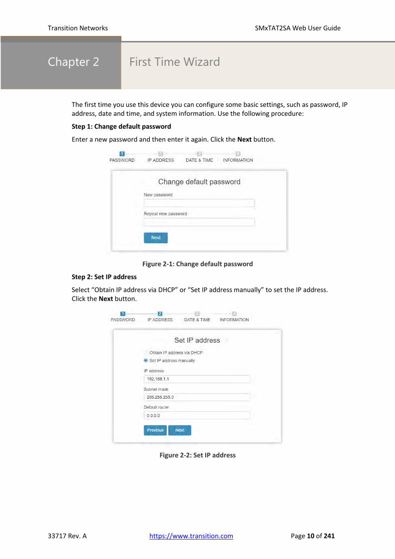
The first time you use this device you can configure some basic settings, such as password, IP address, date and time, and system information. Use the following procedure:
Step 1: Change default password
Enter a new password and then enter it again. Click the Next button.
Figure 2-1: Change default password
Step 2: Set IP address
Select “Obtain IP address via DHCP” or “Set IP address manually” to set the IP address. Click the Next button.
Figure 2-2: Set IP address

Transition Networks SMxTAT2SA Web User Guide
33717 Rev. A https://www.transition.com Page 11 of 241
Step 3: Set date and time
Enable “Automatic data and time” or select manually to set date and time. Click the Next button.
Figure 2-3: Set date and time
Step 4: Set system information
You can set some system information to this device, such as “System contact”, “System name”, “System location”. Click the Apply button.
Figure 2-4: Set system information

Transition Networks SMxTAT2SA Web User Guide
33717 Rev. A https://www.transition.com Page 12 of 241
Menu Bar Overview
Click the Transition Networks logo to return to the Switch > System > System Information page.
Click the icon to toggle between the current menu path and the previous one.
Hover the cursor over any port to see its current status: or .
Click on any port to display its current Detailed Port Statistics page. Top right corner icons:
Save Help Logout
Right click to display other options:

Transition Networks SMxTAT2SA Web User Guide
33717 Rev. A https://www.transition.com Page 13 of 241
Chapter 3 System
This chapter describes the basic configuration tasks including System Information and certain
System parameters (e.g., IP, Advanced IP, Time, Account, IP, Syslog, and NTP.)
3-1 System Information
You can identify the system by configuring system name, location, and contact information.
Additional switch-related information is also provided here.
Web interface
To configure System Information in the web interface:
1. Click System and System Information.
2. Enter System Name, Location, and Contact information (optional).
3. Click the Apply button.
Figure 3-1: System Information (SM16TAT2SA shown)
Parameter descriptions:
Model Name: the specific switch model number (i.e., SM8TAT2SA, SM16TAT2SA, or SM24TAT2SA).
System Description: e.g., Smart Managed Switch, 16-port Gigabit PoE+, 2-port 100/1000 SFP.
Hardware Version: e.g., v1.00.
Mechanical Version: e.g., v1.00.
Firmware Version: the current running version of switch firmware (e.g., v1.00.798).
MAC Address: the switch MAC Address (e.g., 00-40-C7-1C-CB-6E).
Serial Number: the switch (e.g., C021316AR3300004).
System Name: An administratively assigned name for this managed node. By convention, this is the
Transition Networks SMxTAT2SA Web User Guide
33717 Rev. A https://www.transition.com Page 14 of 241
node's fully-qualified domain name. A domain name is a text string drawn from the alphabet (A-Z, a-z),
digits (0-9), minus sign (-). No space characters are permitted as part of a name. The first character
must be an alpha character, and the first or last character must not be a minus sign. The allowed string
length is 0 to 128 characters.
Location: The physical location of this node (e.g., telephone closet, 3rd floor). The allowed string
length is 0 to 128, and the allowed content is an ASCII character from 32 to 126.
Contact: The textual identification of the contact person for this managed node, with information on
how to contact this person. The allowed string length is 0 to 128, and the allowed content is ASCII
characters from 32 to 126.
System Date: the current date: e.g., 2017-01-01 00:12:17 +0000.
System Uptime: the amount of time the switch has been running since the last power cycle (e.g., 0
days, 0:12:33).
Buttons: These buttons are displayed on the System page:
Apply: Click to save changes.
Reset: Click to undo any changes made locally and revert to previously saved values.

33717 Rev. A https://www.transition.com Page 15 of 241
3-2 IP Address
3-2.1 IP Settings
At System > IP Address > IP Settings you can configure the IPv4 address and related parameters.
Web Interface
To configure IP settings in the web interface:
1. Click System, IP Address, IP Settings.
2. Check the “IPv4 DHCP Client Enable” box.
3. Enter the IPv4 Address, Subnet Mask, Gateway, and DNS Server parameters.
4. Click Apply.
Figure 3-2.1: The IP Settings page
Parameter descriptions:
IPv4 DHCP Client Enable: Check the box to enable DHCP Client support globally.
IPv4 Address: e.g., 192.168.1.77.
Subnet Mask: e.g., 255.255.255.0.
Gateway: e.g., 192.168.1.254.
DNS Server: Select either No DNS server, Configured, From this DHCP
interface, or From any DHCP interfaces. If you select “Configured”, enter an IP
address.
If you select “From this DHCP interface”, enter a DNS Server number
(configured in the following section “Advanced IP Settings”.
Buttons
Apply: Click to save changes.
Transition Networks SMxTAT2SA Web User Guide
33717 Rev. A https://www.transition.com Page 16 of 241
3-2.1 Advanced IP Settings
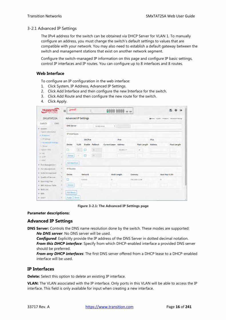
The IPv4 address for the switch can be obtained via DHCP Server for VLAN 1. To manually
configure an address, you must change the switch's default settings to values that are
compatible with your network. You may also need to establish a default gateway between the
switch and management stations that exist on another network segment.
Configure the switch-managed IP information on this page and configure IP basic settings,
control IP interfaces and IP routes. You can configure up to 8 interfaces and 8 routes.
Web Interface
To configure an IP configuration in the web interface:
1. Click System, IP Address, Advanced IP Settings.
2. Click Add Interface and then configure the new Interface for the switch.
3. Click Add Route and then configure the new route for the switch.
4. Click Apply.
Figure 3-2.1: The Advanced IP Settings page
Parameter descriptions:
Advanced IP Settings
DNS Server: Controls the DNS name resolution done by the switch. These modes are supported:
No DNS server: No DNS server will be used.
Configured: Explicitly provide the IP address of the DNS Server in dotted decimal notation.
From this DHCP interface: Specify from which DHCP-enabled interface a provided DNS server
should be preferred.
From any DHCP interfaces: The first DNS server offered from a DHCP lease to a DHCP-enabled
interface will be used.
IP Interfaces
Delete: Select this option to delete an existing IP interface.
VLAN: The VLAN associated with the IP interface. Only ports in this VLAN will be able to access the IP
interface. This field is only available for input when creating a new interface.
Transition Networks SMxTAT2SA Web User Guide
33717 Rev. A https://www.transition.com Page 17 of 241
DHCPv4 Enabled: Enable the IPv4 DHCP client by checking this box. If this option is enabled, the
system will configure the IPv4 address and mask of the interface using the DHCP protocol. The DHCP
client will announce the configured System Name as hostname to provide DNS lookup.
DHCPv4 Fallback: The number of seconds for trying to obtain a DHCP lease. After this Timeout period
expires, a configured IPv4 address will be used as IPv4 interface address. A value of zero disables the
fallback mechanism, such that DHCP will keep retrying until a valid lease is obtained. Legal values are 0
to 4294967295 seconds.
DHCPv4 Current Lease: For IPv4 DHCP interfaces with an active lease, this column show the current
interface address, as provided by the DHCP server.
IPv4 Address: The IPv4 address of the interface in dotted decimal notation.
If DHCP is enabled, this field is not used. The field may also be left blank if IPv4 operation on the
interface is not desired.
IPv4 Mask: The IPv4 network mask, in number of bits (prefix length). Valid values are between 0 and 30
bits for an IPv4 address.
If DHCP is enabled, this field is not used. The field may also be left blank if IPv4 operation on the
interface is not desired.
IPv6 Address: The IPv6 address of the interface. An IPv6 address is in 128-bit records represented as
eight fields of up to four hexadecimal digits with a colon separating each field (:). For example,
fe80::215:c5ff:fe03:4dc7. The symbol :: is a special syntax that can be used as a shorthand way of
representing multiple 16-bit groups of contiguous zeros; but it can appear only once. It can also
represent a legally valid IPv4 address. For example, ::192.1.2.34.
The field may be left blank if IPv6 operation on the interface is not desired.
IPv6 Mask: The IPv6 network mask, in number of bits (prefix length). Valid values are between 1 and
128 bits for an IPv6 address.
The field may be left blank if IPv6 operation on the interface is not desired.
IP Routes
Delete: Select this option to delete an existing IP route.
Network: The destination IP network or host address of this route. Valid format is dotted decimal
notation or a valid IPv6 notation. A default route can use the value 0.0.0.0or IPv6 :: notation.
Mask Length: The destination IP network or host mask, in number of bits (prefix length). It defines how
much of a network address that must match, in order to qualify for this route. Valid values are between
0 and 32 bits respectively 128 for IPv6 routes. Only a default route will have a mask length of 0 (as it will
match anything).
Gateway: The IP address of the IP gateway. Valid format is dotted decimal notation or a valid IPv6
notation. Gateway and Network must be of the same type.
Next Hop VLAN (Only for IPv6): The VLAN ID (VID) of the specific IPv6 interface associated with the
gateway. The given VID ranges from 1 to 4094 and will be effective only when the corresponding IPv6
interface is valid.
If the IPv6 gateway address is link-local, it must specify the next hop VLAN for the gateway.
If the IPv6 gateway address is not link-local, system ignores the next hop VLAN for the gateway.
Buttons
Add Interface: Click to add a new IP interface. A maximum of 8 interfaces is supported.
Add Route: Click to add a new IP route. A maximum of 8 routes is supported.
Apply: Click to save changes.
Reset: Click to undo any changes made locally and revert to previously saved values.

Transition Networks SMxTAT2SA Web User Guide
33717 Rev. A https://www.transition.com Page 18 of 241
3-2.2 IP Status
This page displays the status of the IP protocol layer. The status is defined by the IP interfaces,
the IP routes and the neighbor cache (ARP cache) status.
Web Interface
To display the log configuration in the web interface:
1. Click System, IP Address, and Status.
2. View the IP Configuration information.
Figure 3-2.2: The IP Status page
Parameter descriptions:
IP Interfaces
Interface: Shows the name of the interface (e.g., OS:lo or VLAN1).
Type: Shows the address type of the entry. This may be LINK or IPv4 or IPv6.
Address: Shows the current address of the interface (of the given type; e.g., 192.168.1.77/24 or ::1/128
or 00-40-C7-1C-CB-6E).
Status: Shows the status flags of the interface (and/or address). For example: UP LOOPBACK RUNNING
MTU:16436 Metric:1 or UP BROADCAST RUNNING MULTICAST MTU:1500 Metric:1, or Manual, or Link
Local Address.
IP Routes
Network: Shows the destination IP network or host address of this route (e.g., 192.168.1.0/24).
Gateway: Shows the gateway address of this route (e.g., 192.168.1.254 or ::).

Transition Networks SMxTAT2SA Web User Guide
33717 Rev. A https://www.transition.com Page 19 of 241
Status: Shows the status flags of the route (e.g., UP or UP GATEWAY).
Interface: Shows the name of the interface (e.g., OS:lo or VLAN1).
Neighbor Cache
IP Address: Show the IP address of the entry (e.g., 192.168.1.99).
Link Address: Show the Link (MAC) address for which a binding to the given IP address exists (e.g.,
VLAN1:00-1b-11-b2-6d-4b).
DNS Server
Type: Show the address type of the entry. This may be LINK or IPv4.
IP Address: Show the current address of the interface (of the given type).
Interface: Show the name of the interface.
Buttons
Auto-refresh: Check this box to refresh the page automatically every 3 seconds.
Refresh: Click to refresh the page immediately.

Transition Networks SMxTAT2SA Web User Guide
33717 Rev. A https://www.transition.com Page 20 of 241
3-3 System Time
The switch provides manual and automatic ways to set the system time via NTP. For manual
setting, enter the “Year”, “Month”, “Day”, “Hour” and “Minute” within the valid value range
indicated for each item.
Web Interface
To configure Time in the web interface:
1. Click System and System Time.
2. Specify the Time parameters.
3. Click Apply.
Figure 3-3: The Time Configuration page
Parameter descriptions:
Time Configuration
Clock Source: There are two modes for configuring how the Clock Source from. Select "Local Settings" :
Clock Source from Local Time. Select "NTP Server" : Clock Source from NTP Server.
System Date: Show the current time of the system. The year of system date must be 2000 - 2037.
Time Zone Configuration
Time Zone: Lists various Time Zones worldwide. Select appropriate Time Zone from the drop down
and click Apply to set.
Acronym: You can set the acronym of the time zone. This is a user configurable acronym to identify the
time zone (range: up to 16 characters).
Transition Networks SMxTAT2SA Web User Guide
33717 Rev. A https://www.transition.com Page 21 of 241
Daylight Saving Time Configuration
Daylight Saving Time: This is used to set the clock forward or backward according to the
configurations set below for a defined Daylight Saving Time duration. Select 'Disable' to disable the
Daylight Saving Time configuration. Select 'Recurring' and configure the Daylight Saving Time duration
to repeat the configuration every year. Select 'Non-Recurring' and configure the Daylight Saving Time
duration for single time configuration. (Default: Disabled).
Recurring Configuration
Start time settings:
Month - Select the starting month (Jan – Dec).
Week - Select the starting week number (1-5).
Day - Select the starting day (Mon – Sun).
Hours - Select the starting hour (0-23).
End time settings:
Month - Select the starting month (Jan – Dec).
Week - Select the starting week number (1-5).
Day - Select the starting day (Mon – Sun).
Hours - Select the starting hour (0-23).
Offset settings: Offset - Enter the number of minutes to add during Daylight Saving Time. The valid
range is 1 to 1440 minutes. The default is 60 minutes.
NOTE: The information under “Start Time Settings” and “End Time Settings” displays
what you set on the “Start Time Settings” and “End Time Settings” field information.
Buttons
Apply: Click to save changes.
Reset: Click to undo any changes made locally and revert to previously saved values.

Transition Networks SMxTAT2SA Web User Guide
33717 Rev. A https://www.transition.com Page 22 of 241
Configure NTP Server: At “Clock Source” select NTP Server. then click the Configure NTP Server
button to configure NTP server.
Figure 3-3: The NTP Configuration page
NTP (Network Time Protocol) is used to sync the network time based Greenwich Mean Time (GMT). If
use the NTP mode and select a built-in NTP time server or manually specify an user-defined NTP server
as well as Time Zone, the switch will sync the time in a short after pressing Apply button. Though it
synchronizes the time automatically, NTP does not update the time periodically without user’s
processing.
Time Zone is an offset time off GMT. You have to select the time zone first and then perform time sync
via NTP because the switch will combine this time zone offset and updated NTP time to come out the
local time, otherwise, you will not able to get the correct time. The switch supports configurable time
zone from –12 to +13 step 1 hour. The default Time zone is +8 Hrs.
Parameter descriptions:
Server 1 to 6: Provide the NTP IPv4 or IPv6 address of this switch. IPv6 address is in 128-bit records
represented as eight fields of up to four hexadecimal digits with a colon separating each field (:). For
example, 'fe80::215:c5ff:fe03:4dc7'. The symbol '::' can be used as a shorthand way of representing
multiple 16-bit groups of contiguous zeros; but it can only appear once. It can also represent a legally
valid IPv4 address. For example, '::192.1.2.34'.
Interval: You can specify the time interval in seconds after which a time check and, in case of deviation,
a resynchronization of the internal device clock against the specified timeserver via Network Time
Protocol (NTP) should be performed. The valid range is 10-2880 minutes. The default is 1440 minutes.
Buttons: These buttons are displayed on the SNTP page:
Apply: Click to save changes.
Reset: Click to undo any changes made locally and revert to previously saved values.

Transition Networks SMxTAT2SA Web User Guide
33717 Rev. A https://www.transition.com Page 23 of 241
3-4 System Log
3-4.1 Syslog Configuration
Syslog is a standard for logging program messages. It allows separation of the software that
generates messages from the system that stores them and the software that reports and
analyzes them. It can be used as well a generalized informational, analysis and debugging
messages. It is supported by various devices and receivers across multiple platforms.
Web Interface
To configure Syslog Configuration in the web interface:
1. Click System, Log, and Syslog Configuration.
2. Specify the syslog parameters including the IP Address of Syslog server and Port number.
3. At Mode, select “on” to enable Syslog.
4. Click Apply.
Figure 3-4.1: The System Log Configuration page
Parameter descriptions:
Mode: Select the server mode of operation. When the mode is “on” (enabled) syslog messages will be
sent out to the configured syslog server. The syslog protocol is based on UDP communication and
received on UDP port 514 and the syslog server will not send acknowledgments back to the sender
since UDP is a connectionless protocol and it does not provide acknowledgments. The syslog packet is
always sent out even if the syslog server does not exist. Possible modes are:
On: Enable server mode operation.
Off: Disable server mode operation.
Server 1 to 6: Indicates the IPv4 hosts address of syslog server. If the switch provide DNS feature, it
also can be a host name.
Buttons
Apply: Click to save changes.
Reset: Click to undo any changes made locally and revert to previously saved values.

Transition Networks SMxTAT2SA Web User Guide
33717 Rev. A https://www.transition.com Page 24 of 241
3-4.2 View Log
This page displays the switch system log (Syslog) information.
Web Interface
To display the log configuration in the web interface:
1. Click System, Log, and View Log.
2. View the log information.
Figure 3-4.2: The System Log Information page
Parameter descriptions:
ID: ID (>= 1) of the system log entry.
Level: the level of the system log entry. The following level types are supported:
Debug: debug level message.
Info: informational message.
Notice: normal, but significant, condition.
Warning: warning condition.
Error: error condition.
Crit: critical conditions.
Alert: action must be taken immediately.
Emerg: system is unusable.
Time: Displays the log record by device time; the time of the system log entry.
Message: Displays the log detail message; the message of the system log entry (e.g., LINK-UPDOWN).
Search: Lets you search for the information that you want to view.
Show entries: Lets you choose how many items you want to view per page (i.e., 10, 25, 60, ALL).

Transition Networks SMxTAT2SA Web User Guide
33717 Rev. A https://www.transition.com Page 25 of 241
Buttons
Refresh: Updates the system log entries, starting from the current entry ID.
Clear Logs: Clears all the system log entries and display “No data available in table”.
Next: Updates the system log entries, turn to the next page.
Previous: Updates the system log entries, turn to the previous page.
System Log Message Examples
LINK-UPDOWN: Interface GigabitEthernet 1/1, changed state to up.
WARM-START: Switch just made a warm boot.
LOGIN: Login passed for user 'admin'
LOGOUT: User '' logout
SFP: Interface GigabitEthernet 1/17 rx power 0.00 exceeds Alarm-Low Limitation

Transition Networks SMxTAT2SA Web User Guide
33717 Rev. A https://www.transition.com Page 26 of 241
3-5 LLDP
The switch supports the LLDP. For current information on your switch model, The Link Layer
Discovery Protocol (LLDP) provides a standards-based method for enabling switches to
advertise themselves to adjacent devices and to learn about adjacent LLDP devices.
LLDP is a vendor-neutral Link Layer protocol in the Internet Protocol Suite used by network
devices for advertising their identity, capabilities, and neighbors on a IEEE 802 local area
network, principally wired Ethernet. The protocol is formally referred to by the IEEE as Station
and Media Access Control Connectivity Discovery specified in standards document IEEE
802.1AB.
3-5.1 LLDP Configuration
You can configure LLDP detail parameters on a per-port basis and the settings will take effect
immediately. This page lets you inspect and configure the current LLDP port settings.
Web Interface
To configure LLDP:
1. Click System, LLDP, and LLDP Configuration.
2. Modify LLDP timing parameters.
3. Set the required mode for transmitting or receiving LLDP messages.
4. Specify the information to include in the TLV field of advertised messages.
5. Click Apply.
Figure 3-5.1: The LLDP Configuration page
LLDP Parameter descriptions:
Tx Interval: The switch periodically transmits LLDP frames to its neighbors for having the network
discovery information up-to-date. The interval between each LLDP frame is determined by the Tx
Interval value. Valid values are 5 - 32768 seconds. The default is 30 seconds.

Transition Networks SMxTAT2SA Web User Guide
33717 Rev. A https://www.transition.com Page 27 of 241
Tx Hold: Each LLDP frame contains information about how long the information in the LLDP frame will
be considered valid. The LLDP information valid period is set to Tx Hold multiplied by Tx Interval
seconds. Valid values are 2 - 10 times. The default is 4 times.
Tx Delay: If some configuration is changed (e.g. the IP address) a new LLDP frame is transmitted, but
the time between the LLDP frames will always be at least the value of Tx Delay seconds. Tx Delay cannot
be larger than 1/4 of the Tx Interval value. Valid values are 1 - 8192 seconds. The default is 2 seconds.
Tx Reinit: When a port is disabled, LLDP is disabled or the switch is rebooted, an LLDP shutdown frame
is transmitted to the neighboring units, signaling that the LLDP information isn't valid anymore. Tx
Reinit controls the amount of seconds between the shutdown frame and a new LLDP initialization. Valid
values are 1 - 10 seconds. The default is 2 seconds.
LLDP Port Configuration: The LLDP port settings relate to the currently selected, as reflected by the
page header.
Port: The switch port number of the logical LLDP port.
Mode: Select LLDP mode:
Rx only The switch will not send out LLDP information, but LLDP information from neighbor units
is analyzed.
Tx only The switch will drop LLDP information received from neighbors, but will send out LLDP
information.
Disabled The switch will not send out LLDP information, and will drop LLDP information received
from neighbors.
Enabled the switch will send out LLDP information, and will analyze LLDP information received
from neighbors.
CDP Aware: Select CDP awareness.
The CDP operation is restricted to decoding incoming CDP frames (The switch doesn't transmit CDP
frames). CDP frames are only decoded if LLDP on the port is enabled.
Only CDP TLVs that can be mapped to a corresponding field in the LLDP neighbors’ table are decoded.
All other TLVs are discarded (Unrecognized CDP TLVs and discarded CDP frames are not shown in the
LLDP statistics.). CDP TLVs are mapped onto LLDP neighbors’ table as shown below.
CDP TLV "Device ID" is mapped to the LLDP "Chassis ID" field.
CDP TLV "Address" is mapped to the LLDP "Management Address" field. The CDP address TLV can
contain multiple addresses, but only the first address is shown in the LLDP neighbors’ table.
CDP TLV "Port ID" is mapped to the LLDP "Port ID" field.
CDP TLV "Version and Platform" is mapped to the LLDP "System Description" field.
Both the CDP and LLDP support "system capabilities", but the CDP capabilities cover capabilities that
are not part of the LLDP. These capabilities are shown as "others" in the LLDP neighbors’ table.
If all ports have CDP awareness disabled the switch forwards CDP frames received from neighbor
devices. If at least one port has CDP awareness enabled all CDP frames are terminated by the switch.
NOTE: When CDP awareness on a port is disabled the CDP information isn't removed
immediately, but gets disabled when the hold time is exceeded.
Port Descr: Optional TLV: When checked the "port description" is included in LLDP information
transmitted.

Transition Networks SMxTAT2SA Web User Guide
33717 Rev. A https://www.transition.com Page 28 of 241
Sys Name: Optional TLV: When checked the "system name" is included in LLDP information
transmitted.
Sys Descr: Optional TLV: When checked the "system description" is included in LLDP information
transmitted.
Sys Capa: Optional TLV: When checked the "system capability" is included in LLDP information
transmitted.
Mgmt Addr: Optional TLV: When checked the "management address" is included in LLDP information
transmitted.
Buttons
Apply: Click to save changes.
Reset: Click to undo any changes made locally and revert to previously saved values.

Transition Networks SMxTAT2SA Web User Guide
33717 Rev. A https://www.transition.com Page 29 of 241
3-5.2 LLDP-MED Configuration
Media Endpoint Discovery is an enhancement of LLDP, known as LLDP-MED that provides these
facilities:
Auto-discovery of LAN policies (such as VLAN, Layer 2 Priority and Differentiated services (Diffserv)
settings) enabling plug and play networking.
Device location discovery allows creation of location databases and, in the case of Voice over
Internet Protocol (VoIP), Enhanced 911 services.
Extended and automated power management of Power over Ethernet (PoE) end points is
provided.
Inventory management, allowing network administrators to track their network devices, and
determine their characteristics (manufacturer, software and hardware versions, and serial or asset
number).
This page lets you configure LLDP-MED. This function applies to VoIP devices which support
LLDP-MED.
Web Interface
To configure LLDP-MED:
1. Click System, LLDP, and LLDP-MED Configuration.
2. Modify Fast start repeat count parameter; the default is 4.
3. Modify Coordinates Location parameters.
4. Enter Civic Address Location parameters.
5. Add and configure a new policy.
6. Click Apply, will show following Policy Port Configuration.
7. Select a Policy ID for each port.
8. Click Apply.
Figure 3-5.2: The LLDP-MED Configuration page

Transition Networks SMxTAT2SA Web User Guide
33717 Rev. A https://www.transition.com Page 30 of 241
Parameter descriptions:
Fast start repeat count
Rapid startup and Emergency Call Service Location Identification Discovery of endpoints is a critically
important aspect of VoIP systems in general. In addition, it is best to advertise only those pieces of
information which are specifically relevant to particular endpoint types (for example only advertise the
voice network policy to permitted voice-capable devices), both in order to conserve the limited LLDPU
space and to reduce security and system integrity issues that can come with inappropriate knowledge
of the network policy.
With this in mind LLDP-MED defines an LLDP-MED Fast Start interaction between the protocol and the
application layers on top of the protocol, in order to achieve these related properties. Initially, a
Network Connectivity Device will only transmit LLDP TLVs in an LLDPDU. Only after an LLDP-MED
Endpoint Device is detected, will an LLDP-MED capable Network Connectivity Device start to advertise
LLDP-MED TLVs in outgoing LLDPDUs on the associated port. The LLDP-MED application will
temporarily speed up the transmission of the LLDPDU to start within a second, when a new LLDP-MED
neighbor has been detected in order share LLDP-MED information as fast as possible to new
neighbors.
Because there is a risk of an LLDP frame being lost during transmission between neighbors, it is
recommended to repeat the fast start transmission multiple times to increase the possibility of the
neighbors receiving the LLDP frame. With Fast start repeat count it is possible to specify the number of
times the fast start transmission would be repeated. The recommended value is 4 times, given that 4
LLDP frames with a 1 second interval will be transmitted, when an LLDP frame with new information is
received.
It should be noted that LLDP-MED and the LLDP-MED Fast Start mechanism is only intended to run on
links between LLDP-MED Network Connectivity Devices and Endpoint Devices, and as such does not
apply to links between LAN infrastructure elements, including Network Connectivity Devices, or other
types of links.
Coordinates Location
Latitude: Latitude normalized to within 0-90 degrees with a maximum of 4 digits. It is possible to
specify the direction to either North of the equator or South of the equator.
Longitude: Longitude normalized to within 0-180 degrees with a maximum of 4 digits. It is possible to
specify the direction to either East of the prime meridian or West of the prime meridian.
Altitude: Altitude normalized to within -32767 to 32767 with a maximum of 4 digits.
It is possible to select between two altitude types (floors or meters).
Meters: Representing meters of Altitude defined by the vertical datum specified.
Floors: Representing altitude in a form more relevant in buildings which have different floor-to-floor
dimensions. An altitude = 0.0 is meaningful even outside a building, and represents ground level at the
given latitude and longitude. Inside a building, 0.0 represents the floor level associated with ground
level at the main entrance.
Map Datum: The Map Datum is used for the coordinates given in these options:
WGS84: (Geographical 3D) - World Geodesic System 1984, CRS Code 4327, and Prime Meridian
Name: Greenwich.
NAD83/NAVD88: North American Datum 1983, CRS Code 4269, Prime Meridian Name:
Greenwich; the associated vertical datum is the North American Vertical Datum of 1988 (NAVD88).
This datum pair is to be used when referencing locations on land, not near tidal water (which
would use Datum = NAD83/MLLW).
NAD83/MLLW: North American Datum 1983, CRS Code 4269, Prime Meridian Name: Greenwich;
the associated vertical datum is Mean Lower Low Water (MLLW). This datum pair is to be used
when referencing locations on water/sea/ocean.

Transition Networks SMxTAT2SA Web User Guide
33717 Rev. A https://www.transition.com Page 31 of 241
Civic Address Location: IETF Geopriv Civic Address based Location Configuration Information (Civic
Address LCI).
Country code: The two-letter ISO 3166 country code in capital ASCII letters - Example: DK, DE or US.
State: National subdivisions (state, canton, region, province, prefecture).
County: County, parish, gun (Japan), district.
City: City, township, shi (Japan) - Example: Copenhagen.
City district: City division, borough, city district, ward, chou (Japan).
Block (Neighborhood): Neighborhood, block.
Street: Street - Example: Poppelvej.
Leading street direction: Leading street direction - Example: N.
Trailing street suffix: Trailing street suffix - Example: SW.
Street suffix: Street suffix - Example: Ave, Platz.
House no.: House number - Example: 21.
House no. suffix: House number suffix - Example: A, 1/2.
Landmark: Landmark or vanity address - Example: Columbia University.
Additional location info: Additional location info - Example: South Wing.
Name: Name (residence and office occupant) - Example: Flemming Jahn.
Zip code: Postal/zip code - Example: 2791.
Building: Building (structure) - Example: Low Library.
Apartment: Unit (Apartment, suite) - Example: Apt 42.
Floor: Floor - Example: 4.
Room no. : Room number - Example: 450F.
Place type: Place type - Example: Office.
Postal community name: Postal community name - Example: Leonia.
P.O. Box: Post office box (P.O. BOX) - Example: 12345.
Additional code: Additional code - Example: 1320300003.
Emergency Call Service: Emergency Call Service (e.g. E911 and others), such as defined by TIA or
NENA.
Emergency Call Service: Emergency Call Service ELIN identifier data format is defined to carry the
ELIN identifier as used during emergency call setup to a traditional CAMA or ISDN trunk-based PSAP.
This format consists of a numerical digit string, corresponding to the ELIN to be used for emergency
calling.
Policies: Network Policy Discovery enables the efficient discovery and diagnosis of mismatch issues
with the VLAN configuration, along with the associated Layer 2 and Layer 3 attributes, which apply for a
set of specific protocol applications on that port. Improper network policy configurations are a very
significant issue in VoIP environments that frequently result in voice quality degradation or loss of
service.
Policies are only intended for use with applications that have specific 'real-time' network policy
requirements, such as interactive voice and/or video services.

Transition Networks SMxTAT2SA Web User Guide
33717 Rev. A https://www.transition.com Page 32 of 241
The network policy attributes advertised are:
1. Layer 2 VLAN ID (IEEE 802.1Q-2003)
2. Layer 2 priority value (IEEE 802.1D-2004)
3. Layer 3 Diffserv code point (DSCP) value (IETF RFC 2474)
This network policy is potentially advertised and associated with multiple sets of application types
supported on a given port. The application types specifically addressed are:
1. Voice
2. Guest Voice
3. Softphone Voice
4. Video Conferencing
5. Streaming Video
6. Control / Signalling (conditionally support a separate network policy for the media types above)
A large network may support multiple VoIP policies across the entire organization, and different
policies per application type. LLDP-MED allows multiple policies to be advertised per port, each
corresponding to a different application type. Different ports on the same Network Connectivity Device
may advertise different sets of policies, based on the authenticated user identity or port configuration.
It should be noted that LLDP-MED is not intended to run on links other than between Network
Connectivity Devices and Endpoints, and therefore does not need to advertise the multitude of
network policies that frequently run on an aggregated link interior to the LAN.
Delete: Check to delete the policy. It will be deleted during the next save.
Policy ID: ID for the policy. This is auto generated and is used when selecting the polices that will be
mapped to the specific ports.
Application Type: Intended use of the application types:
1. Voice - for use by dedicated IP Telephony handsets and other similar appliances supporting
interactive voice services. These devices are typically deployed on a separate VLAN for ease of
deployment and enhanced security by isolation from data applications.
2. Voice Signalling (conditional) - for use in network topologies that require a different policy for the
voice signalling than for the voice media. This application type should not be advertised if all the
same network policies apply as those advertised in the Voice application policy.
3. Guest Voice - support a separate 'limited feature-set' voice service for guest users and visitors with
their own IP Telephony handsets and other similar appliances supporting interactive voice services.
4. Guest Voice Signalling (conditional) - for use in network topologies that require a different policy
for the guest voice signalling than for the guest voice media. This application type should not be
advertised if all the same network policies apply as those advertised in the Guest Voice application
policy.
5. Softphone Voice - for use by softphone applications on typical data centric devices, such as PCs or
laptops. This class of endpoints frequently does not support multiple VLANs, if at all, and are typically
configured to use an 'untagged' VLAN or a single 'tagged' data specific VLAN. When a network
policy is defined for use with an 'untagged' VLAN (see Tagged flag below), then the L2 priority field is
ignored and only the DSCP value has relevance.
6. Video Conferencing - for use by dedicated Video Conferencing equipment and other similar
appliances supporting real-time interactive video/audio services.
7. Streaming Video - for use by broadcast or multicast based video content distribution and other
similar applications supporting streaming video services that require specific network policy
treatment. Video applications relying on TCP with buffering would not be an intended use of this
application type.
8. Video Signalling (conditional) - for use in network topologies that require a separate policy for the
video signalling than for the video media. This application type should not be advertised if all the

Transition Networks SMxTAT2SA Web User Guide
33717 Rev. A https://www.transition.com Page 33 of 241
same network policies apply as those advertised in the Video Conferencing application policy.
Tag : Tag indicating whether the specified application type is using a 'tagged' or an 'untagged' VLAN.
Untagged indicates that the device is using an untagged frame format and as such does not include a
tag header as defined by IEEE 802.1Q-2003. In this case, both the VLAN ID and the Layer 2 priority
fields are ignored and only the DSCP value has relevance.
Tagged indicates that the device is using the IEEE 802.1Q tagged frame format, and that both the
VLAN ID and the Layer 2 priority values are being used, as well as the DSCP value. The tagged format
includes an additional field, known as the tag header. The tagged frame format also includes priority
tagged frames as defined by IEEE 802.1Q-2003.
VLAN ID : VLAN identifier (VID) for the port as defined in IEEE 802.1Q-2003.
L2 Priority: L2 Priority is the Layer 2 priority to be used for the specified application type. L2 Priority
may specify one of eight priority levels (0 through 7), as defined by IEEE 802.1D-2004. A value of 0
represents use of the default priority as defined in IEEE 802.1D-2004.
DSCP: DSCP value to be used to provide Diffserv node behavior for the specified application type as
defined in IETF RFC 2474. DSCP may contain one of 64 code point values (0 through 63). A value of 0
represents use of the default DSCP value as defined in RFC 2475.
Port Policies Configuration: Every port may advertise a unique set of network policies or different
attributes for the same network policies, based on the authenticated user identity or port
configuration.
Port: The port number to which the configuration applies.
Policy Id: The set of policies that will apply to a given port. The set of policies is selected by check
marking the checkboxes that corresponds to the policies.
Buttons
Adding New Policy: Click to add a new policy. Specify the Application type, Tag, VLAN ID, L2 Priority
and DSCP for the new policy. Click "Apply".
Apply: Click to save changes.
Reset: Click to undo any changes made locally and revert to previously saved values.

Transition Networks SMxTAT2SA Web User Guide
33717 Rev. A https://www.transition.com Page 34 of 241
3-5.3 LLDP Neighbor
This page provides a status overview for all LLDP neighbors. The displayed table contains a row
for each port on which an LLDP neighbor is detected.
Web Interface
To show LLDP neighbors:
1. Click System, LLDP, and LLDP Neighbor.
2. Click Refresh for manual update web screen.
3. Click Auto-refresh for auto-update web screen.
Figure 3-5.3: The LLDP Neighbor Information page
NOTE: If your network device doesn’t support LLDP the table displays “No LLDP neighbor
information found”.
Parameter descriptions:
Local Port: The port on which the LLDP frame was received.
Chassis ID: The Chassis ID is the identification of the neighbor's LLDP frames.
Port ID: The Remote Port ID is the identification of the neighbor port.
Port Description: Port Description is the port description advertised by the neighbor unit.
System Name: System Name is the name advertised by the neighbor unit.
System Capabilities: System Capabilities describes the neighbor unit's capabilities. The possible
capabilities are:
1. Other
2. Repeater
3. Bridge
4. WLAN Access Point
5. Router
6. Telephone
7. DOCSIS cable device
8. Station only
9. Reserved
When a capability is enabled, the capability is followed by (+). If the capability is disabled, the capability
is followed by (-).
System Description: Displays the system description.

Transition Networks SMxTAT2SA Web User Guide
33717 Rev. A https://www.transition.com Page 35 of 241
Management Address: Management Address is the neighbor unit's address that is used for higher
layer entities to assist discovery by the network management. This could for instance hold the
neighbor's IP address.
Buttons
Auto-refresh: Check this box to refresh the page automatically every 3 seconds.
Refresh: Click to refresh the page immediately.

Transition Networks SMxTAT2SA Web User Guide
33717 Rev. A https://www.transition.com Page 36 of 241
3-5.4 LLDP-MED Neighbor
This page provides a status overview of all LLDP-MED neighbors. The displayed table contains
a row for each port on which an LLDP neighbor is detected. This function applies to VoIP
devices which support LLDP-MED.
Web Interface
To show LLDP-MED neighbor:
1. Click System, LLDP, and LLDP-MED Neighbor.
2. Click Refresh for manual update web screen.
3. Click Auto-refresh for auto-update web screen.
Figure 3-5.4: The LLDP-MED Neighbor Information page
NOTE: If your network without any device supports LLDP-MED then the table
will show “No LLDP-MED neighbor information found”.
Parameter description
Port: The port on which the LLDP frame was received.
Device Type: LLDP-MED Devices are comprised of two primary Device Types: Network Connectivity
Devices and Endpoint Devices.
LLDP-MED Network Connectivity Device Definition: LLDP-MED Network Connectivity Devices, as
defined in TIA-1057, provide access to the IEEE 802 based LAN infrastructure for LLDP-MED Endpoint
Devices. An LLDP-MED Network Connectivity Device is a LAN access device based on any of these
technologies:
1. LAN Switch/Router
2. IEEE 802.1 Bridge
3. IEEE 802.3 Repeater (included for historical reasons)
4. IEEE 802.11 Wireless Access Point
5. Any device that supports the IEEE 802.1AB and MED extensions defined by TIA-1057 and can
relay IEEE 802 frames via any method.

Transition Networks SMxTAT2SA Web User Guide
33717 Rev. A https://www.transition.com Page 37 of 241
LLDP-MED Endpoint Device Definition: LLDP-MED Endpoint Devices, as defined in TIA-1057, are
located at the IEEE 802 LAN network edge, and participate in IP communication service using the
LLDP-MED framework.
Within the LLDP-MED Endpoint Device category, the LLDP-MED scheme is broken into further
Endpoint Device Classes, as defined in the following.
Each LLDP-MED Endpoint Device Class is defined to build on the capabilities defined for the previous
Endpoint Device Class. For-example will any LLDP-MED Endpoint Device claiming compliance as a
Media Endpoint (Class II) also support all aspects of TIA-1057 applicable to Generic Endpoints (Class I),
and any LLDP-MED Endpoint Device claiming compliance as a Communication Device (Class III) will
also support all aspects of TIA-1057 applicable to both Media Endpoints (Class II) and Generic
Endpoints (Class I).
LLDP-MED Generic Endpoint (Class I): The LLDP-MED Generic Endpoint (Class I) definition is
applicable to all endpoint products that require the base LLDP discovery services defined in TIA-1057,
however do not support IP media or act as an end-user communication appliance. Such devices may
include (but are not limited to) IP Communication Controllers, other communication related servers, or
any device requiring basic services as defined in TIA-1057.
Discovery services defined in this class include LAN configuration, device location, network policy,
power management, and inventory management.
LLDP-MED Media Endpoint (Class II): The LLDP-MED Media Endpoint (Class II) definition is
applicable to all endpoint products that have IP media capabilities however may or may not be
associated with a particular end user. Capabilities include all of the capabilities defined for the previous
Generic Endpoint Class (Class I), and are extended to include aspects related to media streaming.
Example product categories expected to adhere to this class include (but are not limited to) Voice /
Media Gateways, Conference Bridges, Media Servers, and similar.
Discovery services defined in this class include media-type-specific network layer policy discovery.
LLDP-MED Communication Endpoint (Class III): The LLDP-MED Communication Endpoint (Class III)
definition is applicable to all endpoint products that act as end user communication appliances
supporting IP media. Capabilities include all of the capabilities defined for the previous Generic
Endpoint (Class I) and Media Endpoint (Class II) classes, and are extended to include aspects related to
end user devices. Example product categories expected to adhere to this class include (but are not
limited to) end user communication appliances, such as IP Phones, PC-based softphones, or other
communication appliances that directly support the end user.
Discovery services defined in this class include provision of location identifier (including ECS / E911
information), embedded L2 switch support, inventory management.
LLDP-MED Capabilities: LLDP-MED Capabilities describes the neighborhood unit's LLDP-MED
capabilities. The possible capabilities are:
1. LLDP-MED capabilities
2. Network Policy
3. Location Identification
4. Extended Power via MDI - PSE
5. Extended Power via MDI - PD
6. Inventory
7. Reserved

Transition Networks SMxTAT2SA Web User Guide
33717 Rev. A https://www.transition.com Page 38 of 241
Application Type: Indicates the primary function of the application(s) defined for this network policy,
advertised by an Endpoint or Network Connectivity Device. The possible application types are:
1. Voice - for use by dedicated IP Telephony handsets and other similar appliances supporting
interactive voice services. These devices are typically deployed on a separate VLAN for ease of
deployment and enhanced security by isolation from data applications.
2. Voice Signalling - for use in network topologies that require a different policy for the voice
signalling than for the voice media.
3. Guest Voice - to support a separate limited feature-set voice service for guest users and visitors
with their own IP Telephony handsets and other similar appliances supporting interactive voice
services.
4. Guest Voice Signalling - for use in network topologies that require a different policy for the
guest voice signalling than for the guest voice media.
5. Softphone Voice - for use by softphone applications on typical data centric devices, such as PCs
or laptops.
6. Video Conferencing - for use by dedicated Video Conferencing equipment and other similar
appliances supporting real-time interactive video/audio services.
7. Streaming Video - for use by broadcast or multicast based video content distribution and other
similar applications supporting streaming video services that require specific network policy
treatment. Video applications relying on TCP with buffering would not be an intended use of this
application type.
8. Video Signalling - for use in network topologies that require a separate policy for the video
signalling than for the video media.
Policy: Indicates that an Endpoint Device wants to explicitly advertise that the policy is required by the
device. Can be either Defined or Unknown
Unknown: The network policy for the specified application type is currently unknown.
Defined: The network policy is defined.
TAG: Indicates whether the specified application type is using a tagged or an untagged VLAN. Can be
Tagged or Untagged.
Untagged: The device is using an untagged frame format and as such does not include a
tag header as defined by IEEE 802.1Q-2003.
Tagged: The device is using the IEEE 802.1Q tagged frame format.
VLAN ID: The VLAN identifier (VID) for the port as defined in IEEE 802.1Q-2003. A value of 1 through
4094 is used to define a valid VLAN ID. A value of 0 (Priority Tagged) is used if the device is using
priority tagged frames as defined by IEEE 802.1Q-2003, meaning that only the IEEE 802.1D priority level
is significant and the default PVID of the ingress port is used instead.
Priority: The Layer 2 priority to be used for the specified application type. One of the eight priority
levels (0 through 7).
DSCP: The DSCP value to be used to provide Diffserv node behavior for the specified application type
as defined in IETF RFC 2474. Contain one of 64 code point values (0 through 63).
Auto-negotiation: Identifies if MAC/PHY auto-negotiation is supported by the link partner.
Auto-negotiation status: identifies if auto-negotiation is currently enabled at the link partner.
If Auto-negotiation is supported and Auto-negotiation status is disabled, the 802.3 PMD operating
mode will be determined the operational MAU type field value rather than by auto-negotiation.
Auto-negotiation Capabilities: shows the link partners MAC/PHY capabilities.

Transition Networks SMxTAT2SA Web User Guide
33717 Rev. A https://www.transition.com Page 39 of 241
Buttons
Auto-refresh: Check this box to refresh the page automatically every 3 seconds.
Refresh: Click to refresh the page immediately.

Transition Networks SMxTAT2SA Web User Guide
33717 Rev. A https://www.transition.com Page 40 of 241
3-5.5 LLDP Statistics
Two types of counters are shown. Global counters are counters that refer to the whole switch,
while Local counters refer to per port counters for the switch.
Web Interface
To show LLDP Statistics:
1. Click System, LLDP, and LLDP Statistics.
2. Click Refresh to manually update the web screen.
3. Click Auto-refresh to auto-update the web screen.
4. Click Clear to clear all counters.
Figure 3-5.5: LLDP Statistics information
Parameter descriptions:
Global Counters
Neighbor entries were last changed: Shows the time when the last entry was last deleted or added. It
also shows the time elapsed since the last change was detected.
Total Neighbors Entries Added: Shows the number of new entries added since switch reboot.
Total Neighbors Entries Deleted: Shows the number of new entries deleted since switch reboot.
Total Neighbors Entries Dropped: Shows the number of LLDP frames dropped due to the entry table
being full.
Total Neighbors Entries Aged Out: Shows the number of entries deleted due to Time-To-Live
expiring.
Local Counters: The displayed table contains a row for each port. The columns hold the following
information:
Local Port: The port on which LLDP frames are received or transmitted.
Transition Networks SMxTAT2SA Web User Guide
33717 Rev. A https://www.transition.com Page 41 of 241
Tx Frames: The number of LLDP frames transmitted on the port.
Rx Frames: The number of LLDP frames received on the port.
Rx Errors: The number of received LLDP frames containing some kind of error.
Frames Discarded: If an LLDP frame is received on a port, and the switch's internal table has run full,
the LLDP frame is counted and discarded. This situation is known as "Too Many Neighbors" in the LLDP
standard. LLDP frames require a new entry in the table when the Chassis ID or Remote Port ID is not
already contained within the table. Entries are removed from the table when a given port's link is down,
an LLDP shutdown frame is received, or when the entry ages out.
TLVs Discarded: Each LLDP frame can contain multiple pieces of information, known as TLVs (TLV is
short for "Type Length Value"). If a TLV is malformed, it is counted and discarded.
TLVs Unrecognized: The number of well-formed TLVs, but with an unknown type value.
Org. Discarded: The number of organizationally received TLVs.
Age-Outs: Each LLDP frame contains information about how long time the LLDP information is valid
(age-out time). If no new LLDP frame is received within the age out time, the LLDP information is
removed, and the Age-Out counter is incremented.
Buttons
Auto-refresh: Check this box to refresh the page automatically every 3 seconds.
Refresh: Click to refresh the page.
Clear: Clears the counters for the selected port.

Transition Networks SMxTAT2SA Web User Guide
33717 Rev. A https://www.transition.com Page 42 of 241
3-6 UPnP
The goals of UPnP (Universal Plug and Play) are to allow devices to connect seamlessly and to
simplify the implementation of networks in the home (data sharing, communications, and
entertainment) and in corporate environments for simplified installation of computer
components.
Web Interface
To configure the UPnP Configuration in the web interface:
1. Click System and UPnP.
2. Scroll to select the mode to enable or disable.
3. Specify the parameters in each field.
4. Click the Apply button to save the setting.
5. To cancel the setting click the Reset button to revert to previously saved values.
Figure 3-6: The UPnP Configuration page
Parameter descriptions: These parameters are displayed on the UPnP Configuration page:
Mode: Indicates the UPnP operation mode. Possible modes are:
Enabled: Enable UPnP mode operation.
Disabled: Disable UPnP mode operation.
When Mode is enabled, two ACEs are added automatically to trap UPNP related packets to the CPU.
The ACEs are automatically removed when the mode is disabled.
TTL: The Time To Live (TTL) value is used by UPnP to send SSDP advertisement messages. Valid values
are 1 - 255 seconds.
Advertising Duration: The duration, carried in SSDP packets, is used to inform a control point or
control points how often it or they should receive an SSDP advertisement message from this switch. If a
control point does not receive any message within the duration, it will think that the switch no longer
exists. Due to the unreliable nature of UDP, in the standard it is recommended that such refreshing of
advertisements to be done at less than one-half of the advertising duration. In the implementation, the
switch sends SSDP messages periodically at the interval one-half of the advertising duration minus 30
seconds. Valid values are in the range 100 to 86400 seconds.
Buttons
Apply: Click to save changes.
Reset: Click to undo any changes made locally and revert to previously saved values.

Transition Networks SMxTAT2SA Web User Guide
33717 Rev. A https://www.transition.com Page 43 of 241
Chapter 4 Port Management
This page lets you configure the Port parameters of the switch, and enable or disable a switch
Port. You can also monitor the ports’ speed and flow control status here.
4-1 Port Configuration
This page displays current port configurations. Ports can also be configured here.
Web Interface
To configure a current Port Configuration in the web interface:
1. Click Port Management and Port Configuration.
2. Specify the Speed Configured, Flow Control, and Power Control.
3. Specify the detail Port alias or description an alphanumeric string describing the full name
and version identification for the system’s hardware type, software version, and networking
application.
4. Click the Apply button.
Figure 4-1: The Port Configuration page
Parameter descriptions:
Port: This is the logical port number for this row.
Link: The current link state is displayed graphically. Green means the link is up and red means it is
down.
Status: Provides the current link speed of the port.
Mode: (Configured Link Speed) Select any available link speed for the given switch port. Only speeds
supported by the specific port are shown. Possible speeds are:
Disabled - Disables the switch port operation.
Auto - Port auto negotiating speed with the link partner and selects the highest speed that is
compatible with the link partner.

Transition Networks SMxTAT2SA Web User Guide
33717 Rev. A https://www.transition.com Page 44 of 241
10Mbps HDX - Forces the cu port in 10Mbps half-duplex mode.
10Mbps FDX - Forces the cu port in 10Mbps full duplex mode.
100Mbps HDX - Forces the cu port in 100Mbps half-duplex mode.
100Mbps FDX - Forces the cu port in 100Mbps full duplex mode.
1Gbps FDX - Forces the port in 1Gbps full duplex
2.5Gbps FDX - Forces the Serdes port in 2.5Gbps full duplex mode.
SFP_Auto_AMS - Automatically determines the speed of the SFP. Note: There is no standardized
way to do SFP auto detect, so here it is done by reading the SFP rom. Due to the missing
standardized way of doing SFP auto detect some SFPs might not be detectable. The port is set in
AMS mode. Cu port is set in Auto mode.
100-FX - SFP port in 100-FX speed. Cu port disabled.
100-FX_AMS - Port in AMS mode. SFP port in 100-FX speed. Cu port in Auto mode.
1000-X - SFP port in 1000-X speed. Cu port disabled.
1000-X_AMS - Port in AMS mode. SFP port in 1000-X speed. Cu port in Auto mode. Ports in AMS
mode with 1000-X speed have Cu port preferred. Ports in AMS mode with 100-FX speed have
fiber port preferred.
Flow Control: When Auto Speed is selected on a port, this section indicates the flow control capability
that is advertised to the link partner. When a fixed-speed setting is selected, that is what is used. The
Current Rx column indicates whether pause frames on the port are obeyed, and the Current Tx column
indicates whether pause frames on the port are transmitted. The Rx and Tx settings are determined by
the result of the last Auto-Negotiation.
Check the configured column to use flow control. This setting is related to the setting for Configured
Link Speed.
Description: Enter up to 63 characters to be descriptive name for identifies this port.
Buttons
Refresh: Click to refresh the Port link Status manually.
Apply: Click to save changes.
Reset: Click to undo any changes made locally and revert to previously saved values.

Transition Networks SMxTAT2SA Web User Guide
33717 Rev. A https://www.transition.com Page 45 of 241
4-2 Port Statistics
The section describes the Port statistics information and provides an overview of general traffic
statistics for all switch ports.
Web Interface
To Display the Port Statistics Overview in the web interface:
1. Click Port Management and Port Statistics.
2. To automatically refresh select “Auto-refresh”.
3. Click “ Refresh“ to refresh the port statistics or clear all information when you click “ Clear”.
4. To view detailed port statistics, click that port.
Figure 4-2: The Port Statistics Overview page
Parameter descriptions:
Port: The logical port for the settings contained in the same row.
Packets: The number of received and transmitted packets per port.
Bytes: The number of received and transmitted bytes per port.
Errors: The number of frames received in error and the number of incomplete transmissions per port.
Drops: The number of frames discarded due to ingress or egress congestion.
Buttons
Auto-refresh: Check this box to refresh the page automatically every 3 seconds.
Refresh: Click to refresh the page.
Clear: Clears the counters for all ports.

Transition Networks SMxTAT2SA Web User Guide
33717 Rev. A https://www.transition.com Page 46 of 241
Click a linked port to see its detailed port statistics. The displayed counters are the totals for receive
and transmit, the size counters for receive and transmit, and the error counters for receive and
transmit.
Figure 4-2: The Detailed Port Statistics page
Parameter descriptions:
Upper left scroll bar: To scroll which port to display the Port statistics with “Port-1”, “Port-2”, ...
Receive Total and Transmit Total
Rx and Tx Packets: The number of received and transmitted (good and bad) packets.
Rx and Tx Octets: The number of received and transmitted (good and bad) bytes. Includes FCS, but
excludes framing bits.
Rx and Tx Unicast: The number of received and transmitted (good and bad) unicast packets.
Rx and Tx Multicast: The number of received and transmitted (good and bad) multicast packets.
Rx and Tx Broadcast: The number of received and transmitted (good and bad) broadcast packets.
Rx and Tx Pause: A count of the MAC Control frames received or transmitted on this port that have an
opcode indicating a PAUSE operation.
Receive and Transmit Size Counters: The number of received and transmitted (good and bad)
packets split into categories based on their respective frame sizes.
Transition Networks SMxTAT2SA Web User Guide
33717 Rev. A https://www.transition.com Page 47 of 241
Receive Error Counters
Rx Drops: The number of frames dropped due to lack of receive buffers or egress congestion.
Rx CRC/Alignment: The number of frames received with CRC or alignment errors.
Rx Undersize: The number of short 1 frames received with valid CRC.
Rx Oversize: The number of long 2 frames received with valid CRC.
Rx Fragments: The number of short 1 frames received with invalid CRC.
Rx Jabber: The number of long 2 frames received with invalid CRC.
Rx Filtered: The number of received frames filtered by the forwarding process.
Short frames are frames that are smaller than 64 bytes.
Long frames are frames that are longer than the configured maximum frame length for this port.
Transmit Error Counters
Tx Drops: The number of frames dropped due to output buffer congestion.
Tx Late/Exc. Coll.: The number of frames dropped due to excessive or late collisions.
Buttons
Auto-refresh: Check this box to refresh the page automatically every 3 seconds.
Refresh: Click to refresh the page.
Clear: Clears the counters for the selected port.

Transition Networks SMxTAT2SA Web User Guide
33717 Rev. A https://www.transition.com Page 48 of 241
4-3 SFP Port Info
This section describes the SFP module detail information when connected to the switch.
The information includes Connector type, Fiber type, wavelength, bit rate, Vendor OUI, etc.
Web Interface
To Display the SFP information in the web interface:
1. Click Port Management and SFP Port Info.
2. View the displayed SFP Information.
Figure 4-3: The SFP Port Information page
Parameter descriptions:
Upper left scroll bar: Use to scroll to the port to display its Port statistics (e.g., “Port-25”, “Port-26”).
Connector Type: Display the connector type, for instance, SFP, SFP Plus, Reserved - LC, SC, ST, LC, etc..
Fiber Type: Display the fiber mode, for instance, Multi-Mode (MM) or Single-Mode (SM).
Tx Central Wavelength: Display the fiber optical transmitting central wavelength, for instance, 850nm,
1310nm, 1550nm, etc.
Bit Rate: Displays the nominal bit rate of the transceiver.
Vendor OUI: Displays the Manufacturer's OUI (Organizationally Unique Identifier) code which is
assigned by IEEE.
Vendor Name: Displays the company name of the module manufacturer.
Vendor P/N: Displays the product name of the naming by module manufacturer.
Vendor Rev (Revision): Displays the module revision.
Vendor SN (Serial Number): Shows the serial number assigned by the manufacturer.
Transition Networks SMxTAT2SA Web User Guide
33717 Rev. A https://www.transition.com Page 49 of 241
Date Code: Shows the date this SFP module was made.
Temperature: Shows the current temperature of SFP module.
Vcc: Shows the working DC voltage of SFP module.
Mon1(Bias) mA: Shows the Bias current of SFP module in milliamps.
Mon2(TX PWR): Shows the transmit power of SFP module in dBm.
Mon3(RX PWR): Shows the receiver power of SFP module in dBm.
Buttons
Auto-refresh: Check this box to refresh the page automatically every 3 seconds.
Refresh: Click to refresh the page.

Transition Networks SMxTAT2SA Web User Guide
33717 Rev. A https://www.transition.com Page 50 of 241
4-4 Energy Efficient Ethernet
This page lets you inspect and configure the current EEE port settings.
EEE (Energy Efficient Ethernet) is defined in IEEE 802.3az as a power saving option that reduces
the power usage when there is very low traffic utilization (or no traffic).
EEE works by powering down circuits when there is no traffic. When a port gets data to be
transmitted all circuits are powered up. The time it takes to power up the circuits is named
wakeup time. The default wakeup time is 17 us for 1Gbit links and 30 us for other link
speeds. EEE devices must agree upon the value of the wakeup time in order to make sure that
both the receiving and transmitting device has all circuits powered up when traffic is
transmitted. The devices can exchange information about the devices wakeup time using
the LLDP protocol.
Web Interface
To configure Energy Efficient Ethernet in the web interface:
1. Click Port Management and Energy Efficient Ethernet.
2. The port to select enable or disable Energy Efficient Ethernet.
3. Click the Apply button to save the settings.
4. To cancel the setting click the Reset button to revert to previously saved values.
Figure 4-4: The Energy Efficient Ethernet Configuration page
Parameter descriptions:
Port: The switch port number of the logical EEE port.
Configure: Controls whether EEE is enabled for this switch port.
Buttons
Apply: Click to save changes.
Reset: Click to undo any changes made locally and revert to previously saved values.

Transition Networks SMxTAT2SA Web User Guide
33717 Rev. A https://www.transition.com Page 51 of 241
4-5 Link Aggregation
4-5.1 Port
This section describes Port setting/status used to configure the trunk property of each port.
Web Interface
To configure the trunk property of each and every port in the web interface:
1. Click Port Management, Link Aggregation, and port.
2. Specify the Method, Group, LACP Role and LACP Timeout.
3. Click the Apply button to save the setting.
4. To cancel the setting click the Reset button to revert to previously saved values.
Figure 4-5.1: The Trunk Port Setting/Status page
Parameter description :
Port: The logical port for the settings contained in the same row.
Method: This determines the method a port uses to aggregate with other ports.
None: A port does not want to aggregate with any other port should choose this default setting.
LACP: A port use LACP as its trunk method to get aggregated with other ports also using LACP.
Static: A port use Static Trunk as its trunk method to get aggregated with other ports also using
Static Trunk.
Group: Ports choosing the same trunking method other than “None” must be assigned a unique
Group number (i.e. Group ID, valid value is from 1 to 8) in order to declare that they wish to aggregate
with each other.
LACP Role: This field is only referenced when a port’s trunking method is LACP.
Active: An Active LACP port begins to send LACPDU to its link partner right after the LACP
protocol entity started to take control of this port.
Passive: A Passive LACP port will not actively send LACPDU out before it receives an LACPDU
from its link partner.
Transition Networks SMxTAT2SA Web User Guide
33717 Rev. A https://www.transition.com Page 52 of 241
LACP Timeout: The Timeout controls the period between BPDU transmissions.
Fast: It will transmit LACP packets each second,
Slow: It will wait for 30 seconds before sending a LACP packet.
Aggtr: Aggtr is an abbreviation of “aggregator”. Every port is also an aggregator, and its own
aggregator ID is the same as its own Port No. We can regard an aggregator as a representative of a
trunking group. Ports with same Group ID and using same trunking method will have the opportunity
to aggregate to a particular aggregator port. This aggregator port is usually the port with the smallest
Port No. within the trunking group.
Status: This field represents the trunking status of a port which uses a trunking method other than
“None”. It also represents the management link status of a port which uses the “None” trunking
method. “---“ means “not ready”
Buttons
Apply: Click to save changes.
Reset: Click to undo any changes made locally and revert to previously saved values.

Transition Networks SMxTAT2SA Web User Guide
33717 Rev. A https://www.transition.com Page 53 of 241
4-5.2 Aggregator View
To display the current port trunking information from the aggregator point of view.
Web Interface
To see the LACP detail in the web interface:
1. Click Port Management, Link Aggregation, and Aggregator View.
2. Click the Lacp Detail radio button.
Figure 4-5.2: The Aggregator View page
Parameter descriptions:
Aggregator: Shows the aggregator ID of every port. In fact, every port is also an aggregator, and its
own aggregator ID is the same as its own Port No.
Method: Show the method a port uses to aggregate with other ports.
Member Ports: Show all member ports of an aggregator (port).
Ready Ports: Show only the ready member ports within an aggregator (port).
Lacp Detail: Lets you select the port that you want to see the LACP Detail.

Transition Networks SMxTAT2SA Web User Guide
33717 Rev. A https://www.transition.com Page 54 of 241
Buttons
Lacp Detail: Click this button to display the aggregator information, as described below.
Figure 4-5.2: The LACP Detail page
Parameter descriptions:
Actor
System Priority: Show the System Priority part of the aggregation Actor. (1-65535).
Mac Address: The system ID of the aggregation Actor.
Actor Port: The actor's port number connected to this port.
Actor Key: The Key that the actor has assigned to this aggregation ID.
Partner
System Priority: Show the System Priority part of the aggregation partner. (1-65535)
Mac Address: The system ID of the aggregation partner.
Partner Port: The partner's port number connected to this port.
Partner Key: The Key that the partner has assigned to this aggregation ID.
Trunk Status: This field represents the trunking status of a port which uses a trunking method other
than “None”. It also represents the management link status of a port which uses the “None” trunking
method. “---“ means “not ready”
Button
Back: Click to undo any changes made locally and return to the Users.
Messages: Method must be LACP and Member Ports must have a port at least.

Transition Networks SMxTAT2SA Web User Guide
33717 Rev. A https://www.transition.com Page 55 of 241
4-5.3 Aggregation Hash Mode
Web Interface
To configure the Aggregation hash mode in the web interface:
1. Click Port Management, Link Aggregation, and Aggregation Hash Mode.
2. Click Hash Code Contributors to select the mode.
3. Click the Apply button to save the setting.
4. To cancel the setting, click the Reset button to previously saved values.
Figure 4-5.3: Aggregation Hash Mode
Parameter descriptions:
Hash Code Contributors
src-mac: The Source MAC address can be used to calculate the destination port for the frame. Check to
enable the use of the Source MAC address, or uncheck to disable. By default, Source MAC Address is
enabled.
dst-mac: The Destination MAC Address can be used to calculate the destination port for the frame.
Check to enable the use of the Destination MAC Address, or uncheck to disable. By default, Destination
MAC Address is disabled.
ip: The IP address can be used to calculate the destination port for the frame. Check to enable the
use of the IP Address, or uncheck to disable. By default, IP Address is enabled.
src-dst-mac: Source MAC Address + Destination MAC Address.
src-ip: Source MAC Address + IP Address.
dst-ip: Destination MAC Address + IP Address.
src-dst-ip: Source MAC Address + Destination MAC Address + IP Address.
Buttons
Apply : Click to save changes.
Reset : Click to undo any changes made locally and revert to previously saved values.
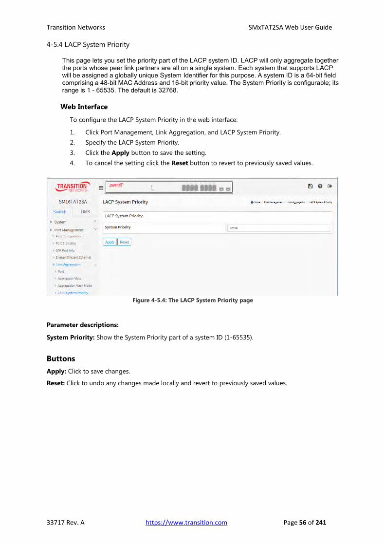
Transition Networks SMxTAT2SA Web User Guide
33717 Rev. A https://www.transition.com Page 56 of 241
4-5.4 LACP System Priority
This page lets you set the priority part of the LACP system ID. LACP will only aggregate together the ports whose peer link partners are all on a single system. Each system that supports LACP will be assigned a globally unique System Identifier for this purpose. A system ID is a 64-bit field comprising a 48-bit MAC Address and 16-bit priority value. The System Priority is configurable; its range is 1 - 65535. The default is 32768.
Web Interface
To configure the LACP System Priority in the web interface:
1. Click Port Management, Link Aggregation, and LACP System Priority.
2. Specify the LACP System Priority.
3. Click the Apply button to save the setting.
4. To cancel the setting click the Reset button to revert to previously saved values.
Figure 4-5.4: The LACP System Priority page
Parameter descriptions:
System Priority: Show the System Priority part of a system ID (1-65535).
Buttons
Apply: Click to save changes.
Reset: Click to undo any changes made locally and revert to previously saved values.

Transition Networks SMxTAT2SA Web User Guide
33717 Rev. A https://www.transition.com Page 57 of 241
4-6 Loop Protection
4-6.1 Configuration
Loop Protection is used to detect the presence of traffic. When the switch receives packet’s
(looping detection frame) MAC address the same as oneself from port, Loop Protection is
shown. The port will be locked when it receives the looping Protection frames. If you want to
resume the locked port, find and remove the looping path, then select resume the locked port
and click on “Resume” to turn on the locked ports.
Web Interface
To configure the Loop Protection parameters in the web interface:
1. Click Port Management, Loop Protection, and Configuration.
2. Select “on” to enable port Loop Protection globally.
3. Click the Apply button to save the setting.
4. To cancel the setting, click the Reset button to previously saved values
Figure 4-6.1: The Loop Protection Configuration page
Parameter descriptions:
Global Configuration
Enable Loop Protection: Controls whether loop protections is enabled (as a whole).
Transmission Time: The interval between each loop protection PDU sent on each port. Valid values are
1 to 10 seconds.
Shutdown Time: The period (in seconds) for which a port will be kept disabled in the event of a loop is
detected (and the port action shuts down the port). Valid values are 0 to 604800 seconds (7 days).
A value of zero will keep a port disabled (until next device restart).
Port Configuration
Port: The switch port number of the port.
Enable: Controls whether loop protection is enabled on this switch port.

Transition Networks SMxTAT2SA Web User Guide
33717 Rev. A https://www.transition.com Page 58 of 241
Action: Configures the action performed when a loop is detected on a port. Valid values are Shutdown
Port, Shutdown Port and Log, or Log Only.
Tx Mode: Controls whether the port is actively generating loop protection PDUs, or whether it is just
passively looking for looped PDUs.
Buttons
Apply: Click to save changes.
Reset: Click to undo any changes made locally and revert to previously saved values.

Transition Networks SMxTAT2SA Web User Guide
33717 Rev. A https://www.transition.com Page 59 of 241
4-6.2 Status
This section displays the loop protection port status.
Web Interface
To display the Loop Protection status in the web interface:
1. Click Port Management, Loop Protection, and Status.
2. To automatically refresh the information select “Auto refresh”.
3. Click “Refresh” to refresh the Loop Protection Status.
Figure 4-6.2: Loop Protection Status
Parameter descriptions:
Port: The switch port number of the logical port.
Action: The currently configured port action (Shutdown Port, Shutdown Port and
Log, Log Only).
Transmit: The currently configured port transmit mode.
Loops: The number of loops detected on this port.
Status: The current loop protection status of the port.
Loop: Whether a loop is currently detected on the port.
Time of Last Loop: The time of the last loop event detected.
Buttons
Auto-refresh: Check this box to refresh the page automatically every 3 seconds.
Refresh: Click to refresh the page immediately.

Transition Networks SMxTAT2SA Web User Guide
33717 Rev. A https://www.transition.com Page 60 of 241
Chapter 5 PoE Management
PoE (Power over Ethernet) is used to transmit electrical power to remote
devices over standard Ethernet cable. It could, for example, be used for
powering IP telephones, wireless LAN access points and other equipment,
where it would be difficult or expensive to connect the equipment to
main power supply.
5-1 PoE Configuration
This page lets you view and configure current PoE port settings and show PoE Supply power.
Web Interface
To configure Power over Ethernet in the web interface:
1. Click PoE Management and PoE Configuration.
2. Specify the PoE or PoE+ Mode, PoE Schedule, Priority and Maximum Power (W).
3. Click Apply to save the configuration.
4. To cancel the setting, click the Reset button to previously saved values.
Figure 5-1: PoE Configuration
Parameter descriptions:
PoE Power Supply Configuration
Primary Power Supply [W]: Displays the primary power supply power in watts.
Capacitor Detection: Check to enable or uncheck to disable the capacitor configuration. Check to
enable legacy IP phones support.

Transition Networks SMxTAT2SA Web User Guide
33717 Rev. A https://www.transition.com Page 61 of 241
PoE Port Configuration
Port: This is the logical port number for this row.
PoE Mode: The PoE Mode represents the PoE operating mode for the port. Enable or Disable PoE.
PoE Schedule: Disable PoE Scheduling or select a PoE Schedule profile for each port.
Priority: The Priority represents the ports priority. There are three levels of power priority named Low,
High and Critical. The priority is used in the case where the remote devices require more power than
the power supply can deliver. In this case the port with the lowest priority will be turn off starting from
the port with the highest port number.
Maximum Power [W]: The Maximum Power value contains a numerical value that indicates the
maximum power in watts that can be delivered to a remote device. The maximum allowed value is 30
Watts.
Buttons
Apply: Click to save changes.
Reset: Click to undo any changes made locally and revert to previously saved values.

Transition Networks SMxTAT2SA Web User Guide
33717 Rev. A https://www.transition.com Page 62 of 241
5-2 PoE Status
This page lets you view the current status of all PoE ports.
Web Interface
To display PoE Status in the web interface:
1. Click PoE Management and PoE Status.
2. Scroll “Auto-refresh” to on or off.
3. Click “Refresh” to refresh the port detailed statistics.
Figure 5-2: The PoE Status page
Parameter descriptions:
Local Port: The logical port number for this row.
PD Class: Each PD is classified according to a class that defines the maximum power the PD will use.
The PD Class shows the PDs class:
Class 0: Max. power 15.4 W
Class 1: Max. power 4.0 W
Class 2: Max. power 7.0 W
Class 3: Max. power 15.4 W
Class 4: Max. power 30.0 W
Power Allocated: The Power Allocated shows the amount of power the switch has allocated for the PD.
Power Used: The Power Used shows how much power the PD currently is using.
Current Used: The Power Used shows how much current the PD currently is using.
Priority: The Priority shows the port's priority configured by the user (e.g., Critical, High, or Low).
Port Status: The Port Status shows the port's status. The status can be one of the following values:
PoE not available - No PoE chip found: PoE not supported for the port.
PoE turned OFF - PoE disabled: PoE is disabled by user.
PoE turned OFF - Power budget exceeded: The total requested or used power by the PDs
exceeds the maximum power the Power Supply can deliver, and port(s) with the lowest priority
is/are powered down. A port's PoE can be revoked for one of two reasons: 1) Port power budget
exceeded, or 2) Total power budget exceeded.
No PD detected: No PD detected for the port.

Transition Networks SMxTAT2SA Web User Guide
33717 Rev. A https://www.transition.com Page 63 of 241
PoE turned OFF - PD overload: The PD has requested or used more power than the port can
deliver, and is powered down.
PoE turned OFF: PD is off.
Invalid PD: PD detected, but is not working correctly.
Buttons
Auto-refresh: Check this box to refresh the page automatically every 3 seconds.
Refresh: Click to refresh the page immediately.
Five PD Classes are defined by the IEEE standards:
Class Usage Classification current [mA]
Power range [W]
Class description
0 Default 0–4 0.44–12.94 Classification unimplemented
1 Optional 9–12 0.44–3.84 Very Low power
2 Optional 17–20 3.84–6.49 Low power 3 Optional 26–30 6.49–12.95 Mid power
4 Valid for 802.3at (Type 2) devices, not allowed for 802.3af devices 36–44 36–44 12.95–25.50 High power
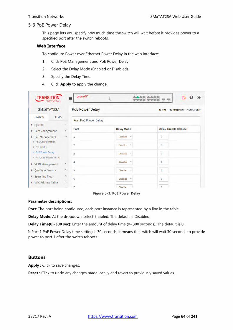
Transition Networks SMxTAT2SA Web User Guide
33717 Rev. A https://www.transition.com Page 64 of 241
5-3 PoE Power Delay
This page lets you specify how much time the switch will wait before it provides power to a
specified port after the switch reboots.
Web Interface
To configure Power over Ethernet Power Delay in the web interface:
1. Click PoE Management and PoE Power Delay.
2. Select the Delay Mode (Enabled or Disabled).
3. Specify the Delay Time.
4. Click Apply to apply the change.
Figure 5-3: PoE Power Delay
Parameter descriptions:
Port: The port being configured; each port instance is represented by a line in the table.
Delay Mode: At the dropdown, select Enabled. The default is Disabled.
Delay Time(0~300 sec): Enter the amount of delay time (0~300 seconds). The default is 0.
If Port 1 PoE Power Delay time setting is 30 seconds, it means the switch will wait 30 seconds to provide
power to port 1 after the switch reboots.
Buttons
Apply : Click to save changes.
Reset : Click to undo any changes made locally and revert to previously saved values.
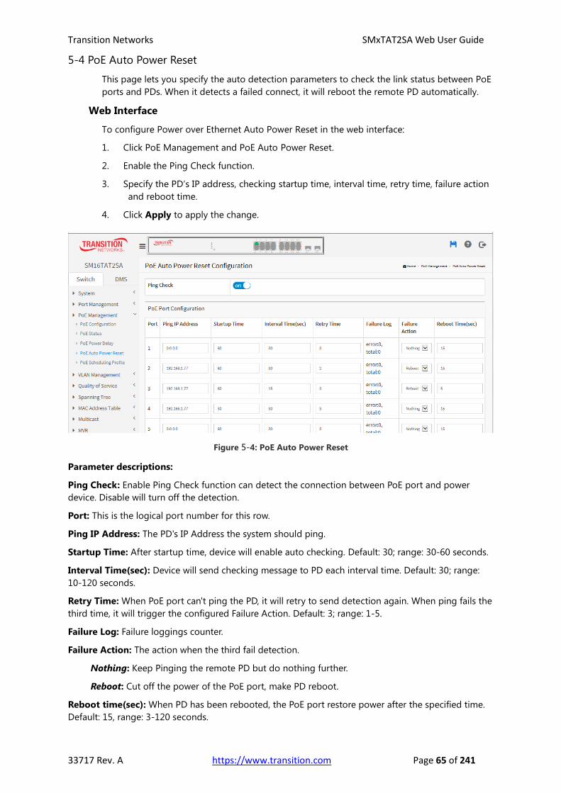
Transition Networks SMxTAT2SA Web User Guide
33717 Rev. A https://www.transition.com Page 65 of 241
5-4 PoE Auto Power Reset
This page lets you specify the auto detection parameters to check the link status between PoE
ports and PDs. When it detects a failed connect, it will reboot the remote PD automatically.
Web Interface
To configure Power over Ethernet Auto Power Reset in the web interface:
1. Click PoE Management and PoE Auto Power Reset.
2. Enable the Ping Check function.
3. Specify the PD’s IP address, checking startup time, interval time, retry time, failure action
and reboot time.
4. Click Apply to apply the change.
Figure 5-4: PoE Auto Power Reset
Parameter descriptions:
Ping Check: Enable Ping Check function can detect the connection between PoE port and power
device. Disable will turn off the detection.
Port: This is the logical port number for this row.
Ping IP Address: The PD's IP Address the system should ping.
Startup Time: After startup time, device will enable auto checking. Default: 30; range: 30-60 seconds.
Interval Time(sec): Device will send checking message to PD each interval time. Default: 30; range:
10-120 seconds.
Retry Time: When PoE port can't ping the PD, it will retry to send detection again. When ping fails the
third time, it will trigger the configured Failure Action. Default: 3; range: 1-5.
Failure Log: Failure loggings counter.
Failure Action: The action when the third fail detection.
Nothing: Keep Pinging the remote PD but do nothing further.
Reboot: Cut off the power of the PoE port, make PD reboot.
Reboot time(sec): When PD has been rebooted, the PoE port restore power after the specified time.
Default: 15, range: 3-120 seconds.

Transition Networks SMxTAT2SA Web User Guide
33717 Rev. A https://www.transition.com Page 66 of 241
Buttons
Apply : Click to save changes.
Reset : Click to undo any changes made locally and revert to previously saved values.

Transition Networks SMxTAT2SA Web User Guide
33717 Rev. A https://www.transition.com Page 67 of 241
5-5 PoE Scheduling Profile
This page lets you define the profile for PoE scheduling.
Figure 5-5: PoE Auto Power Reset
Parameters:
Profile: The index of profile. There are 16 profiles in the configuration.
Name: The name of profile. The default name is "Profile 1". You can define the name for identifying the
profile.
Week Day: The day to schedule PoE.
Start Time: The time to start PoE. The time 00:00 means the first second of this day.
End Time: The time to stop PoE. The time 00:00 means the last second of this day.
Buttons
Apply: Click to save changes.

Transition Networks SMxTAT2SA Web User Guide
33717 Rev. A https://www.transition.com Page 68 of 241
Chapter 6 VLAN Management
6-1 VLAN Configuration
This page lets you assign a specific VLAN for management purpose. The
management VLAN is used to establish an IP connection to the switch from a
workstation connected to a port in the VLAN. This connection supports a VSM,
SNMP, and Telnet session. By default, the active management VLAN is VLAN 1,
but you can designate any VLAN as the management VLAN using the
Management VLAN window. Only one management VLAN can be active at a
time.
When you specify a new management VLAN, your HTTP connection to the old
management VLAN is lost. For this reason, you should have a connection
between your management station and a port in the new management VLAN or
connect to the new management VLAN through a multi-VLAN route.
Web Interface
To configure VLAN membership configuration in the web interface:
1. Click VLAN Management and VLAN Configuration.
2. Configure for existing VLANs, Ethertype, port types, ingress/egress, and allowed VLANs.
3. Click the Apply button.
Figure 6-1: The VLAN Configuration page
Parameter descriptions:
Global VLAN Configuration
Allowed Access VLANs: This field shows the VLANs that are created on the switch. By default, only
VLAN 1 exists. More VLANs may be created by using a list syntax where the individual elements are
separated by commas. Ranges are specified with a dash separating the lower and upper bound. The
following example will create VLANs 1, 10, 11, 12, 13, 200, and 300: 1,10-13,200,300. Spaces are allowed
in between the delimiters.
Ethertype for Custom S-ports: This field specifies the Ethertype/TPID (specified in hexadecimal) used
for Custom S-ports. The setting is in force for all ports whose Port Type is set to S-Custom-Port.

Transition Networks SMxTAT2SA Web User Guide
33717 Rev. A https://www.transition.com Page 69 of 241
Port VLAN Configuration
Port: This is the logical port number of this row.
Mode: The port mode (default is Access) determines the fundamental behavior of the port in question. A port can
be in one of three modes as described below. Whenever a particular mode is selected, the remaining fields in that
row will be either grayed out or made changeable depending on the mode in question.
Grayed out fields show the value that the port will get when the mode is applied.
Access: Access ports are normally used to connect to end stations. Dynamic features like Voice VLAN may add the
port to more VLANs behind the scenes. Access ports have these characteristics:
• Member of exactly one VLAN, the Port VLAN (a.k.a. Access VLAN), which by default is 1,
• accepts untagged frames and C-tagged frames,
• discards all frames that are not classified to the Access VLAN,
• on egress all frames are transmitted untagged.
Trunk: Trunk ports can carry traffic on multiple VLANs simultaneously, and are normally used to connect to other
switches. Trunk ports have these characteristics:
• By default, a trunk port is member of all existing VLANs. This may be limited by the use of Allowed VLANs,
• unless VLAN Trunking is enabled on the port, frames classified to a VLAN that the port is not a member of will
be discarded,
• by default, all frames but frames classified to the Port VLAN (a.k.a. Native VLAN) get tagged on egress. Frames
classified to the Port VLAN do not get C-tagged on egress,
• egress tagging can be changed to tag all frames, in which case only tagged frames are accepted on ingress,
• VLAN trunking may be enabled.
Hybrid: Hybrid ports resemble trunk ports in many ways, but adds additional port configuration features. In
addition to the characteristics described for trunk ports, hybrid ports have these abilities:
• Can be configured to be VLAN tag unaware, C-tag aware, S-tag aware, or S-custom-tag aware,
• ingress filtering can be controlled,
• ingress acceptance of frames and configuration of egress tagging can be configured independently.
Port VLAN: Determines the port's VLAN ID (a.k.a. PVID). Allowed VLANs are in the range 1 through 4095; the
default is 1.
On ingress, frames get classified to the Port VLAN if the port is configured as VLAN unaware, the frame is
untagged, or VLAN awareness is enabled on the port, but the frame is priority tagged (VLAN ID = 0).
On egress, frames classified to the Port VLAN do not get tagged if Egress Tagging configuration is set to untag
Port VLAN.
The Port VLAN is called an "Access VLAN" for ports in Access mode and Native VLAN for ports in Trunk or Hybrid
mode.
Port Type : Ports in hybrid mode allow for changing the port type, that is, whether a frame's VLAN tag is used to
classify the frame on ingress to a particular VLAN, and if so, which TPID it reacts on. Likewise, on egress, the Port
Type determines the TPID of the tag, if a tag is required.
Unaware: On ingress, all frames, whether carrying a VLAN tag or not, get classified to the Port VLAN, and possible
tags are not removed on egress.
C-Port: On ingress, frames with a VLAN tag with TPID = 0x8100 get classified to the VLAN ID embedded in the tag.
If a frame is untagged or priority tagged, the frame gets classified to the Port VLAN. If frames must be tagged on
egress, they will be tagged with a C-tag.
S-Port: On ingress, frames with a VLAN tag with TPID = 0x8100 or 0x88A8 get classified to the VLAN ID embedded
in the tag. If a frame is untagged or priority tagged, the frame gets classified to the Port VLAN. If frames must be
tagged on egress, they will be tagged with an S-tag.
S-Custom-Port: On ingress, frames with a VLAN tag with a TPID = 0x8100 or equal to the Ethertype configured for
Custom-S ports get classified to the VLAN ID embedded in the tag. If a frame is untagged or priority tagged, the
frame gets classified to the Port VLAN. If frames must be tagged on egress, they will be tagged with the custom
S-tag.
Ingress Filtering: Hybrid ports allow for changing ingress filtering. Access and Trunk ports always have ingress
filtering enabled.
If ingress filtering is enabled (checkbox is checked), frames classified to a VLAN that the port is not a member of
get discarded.
If ingress filtering is disabled, frames classified to a VLAN that the port is not a member of are accepted and
forwarded to the switch engine. However, the port will never transmit frames classified to VLANs that it is not a
member of.

Transition Networks SMxTAT2SA Web User Guide
33717 Rev. A https://www.transition.com Page 70 of 241
VLAN Trunking: Trunk and Hybrid ports allow for enabling VLAN trunking.
When VLAN trunking is enabled, frames classified to unknown VLANs are accepted on the port whether ingress
filtering is enabled. This is useful in scenarios where a cloud of intermediary switches must bridge VLANs that
haven't been created. By configuring the ports that connect the cloud of switches as trunking ports, they can
seemlessly carry those VLANs from one end to the other.
Ingress Acceptance: Hybrid ports allow for changing the type of frames that are accepted on ingress.
Tagged and untagged: both tagged and untagged frames are accepted.
Tagged Only: Only tagged frames are accepted on ingress. Untagged frames are discarded.
Untagged Only: Only untagged frames are accepted on ingress. Tagged frames are discarded.
Egress Tagging: Ports in Trunk and Hybrid mode may control the tagging of frames on egress.
Untag Port VLAN: Frames classified to the Port VLAN are transmitted untagged. Other frames are transmitted
with the relevant tag.
Tag All: All frames, whether classified to the Port VLAN or not, are transmitted with a tag.
Untag All: All frames, whether classified to the Port VLAN or not, are transmitted without a tag. This option is only
available for ports in Hybrid mode.
Allowed VLANs: Ports in Trunk and Hybrid mode may control which VLANs they are allowed to become
members of. Access ports can only be member of one VLAN, the Access VLAN.
The field's syntax is identical to the syntax used in the Existing VLANs field. By default, a port may become member
of all possible VLANs, and is therefore set to 1-4095.
The field may be left empty, which means that the port will not be member of any of the existing VLANs, but if it is
configured for VLAN Trunking it will still be able to carry all unknown VLANs.
Buttons
Apply: Click to save changes.
Reset: Click to undo any changes made locally and revert to previously saved values.
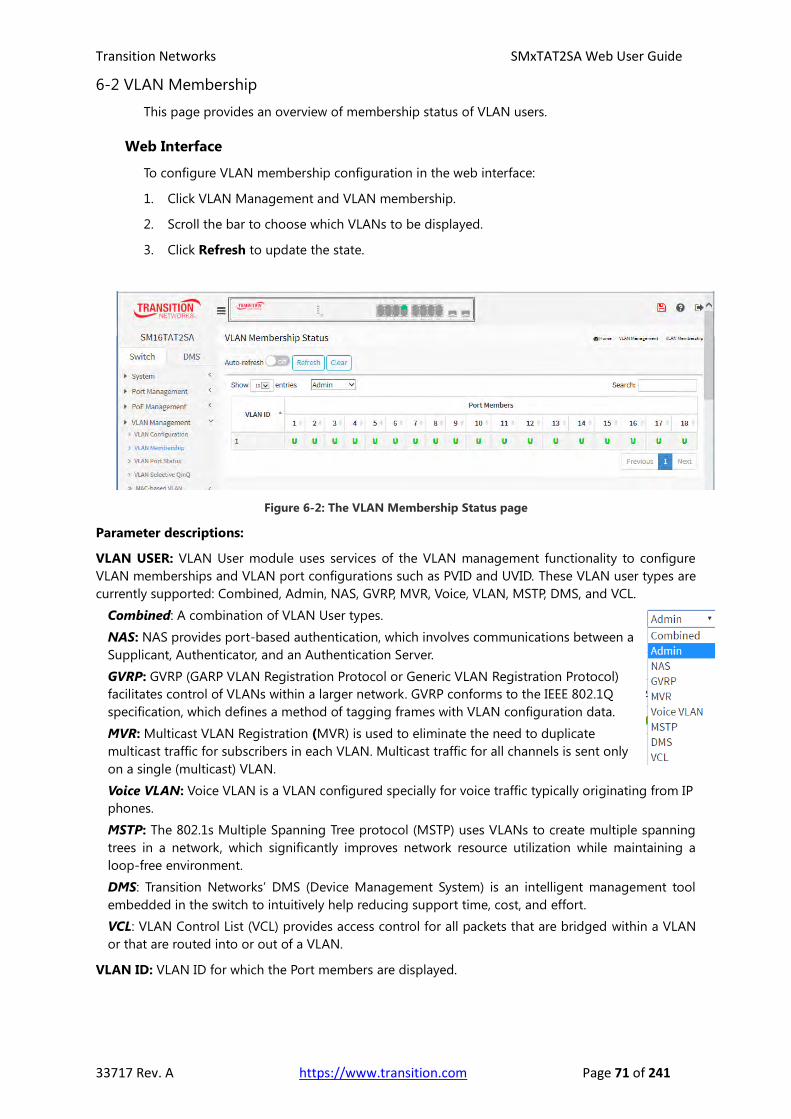
Transition Networks SMxTAT2SA Web User Guide
33717 Rev. A https://www.transition.com Page 71 of 241
6-2 VLAN Membership
This page provides an overview of membership status of VLAN users.
Web Interface
To configure VLAN membership configuration in the web interface:
1. Click VLAN Management and VLAN membership.
2. Scroll the bar to choose which VLANs to be displayed.
3. Click Refresh to update the state.
Figure 6-2: The VLAN Membership Status page
Parameter descriptions:
VLAN USER: VLAN User module uses services of the VLAN management functionality to configure
VLAN memberships and VLAN port configurations such as PVID and UVID. These VLAN user types are
currently supported: Combined, Admin, NAS, GVRP, MVR, Voice, VLAN, MSTP, DMS, and VCL.
Combined: A combination of VLAN User types.
NAS: NAS provides port-based authentication, which involves communications between a
Supplicant, Authenticator, and an Authentication Server.
GVRP: GVRP (GARP VLAN Registration Protocol or Generic VLAN Registration Protocol)
facilitates control of VLANs within a larger network. GVRP conforms to the IEEE 802.1Q
specification, which defines a method of tagging frames with VLAN configuration data.
MVR: Multicast VLAN Registration (MVR) is used to eliminate the need to duplicate
multicast traffic for subscribers in each VLAN. Multicast traffic for all channels is sent only
on a single (multicast) VLAN.
Voice VLAN: Voice VLAN is a VLAN configured specially for voice traffic typically originating from IP
phones.
MSTP: The 802.1s Multiple Spanning Tree protocol (MSTP) uses VLANs to create multiple spanning
trees in a network, which significantly improves network resource utilization while maintaining a
loop-free environment.
DMS: Transition Networks’ DMS (Device Management System) is an intelligent management tool
embedded in the switch to intuitively help reducing support time, cost, and effort.
VCL: VLAN Control List (VCL) provides access control for all packets that are bridged within a VLAN
or that are routed into or out of a VLAN.
VLAN ID: VLAN ID for which the Port members are displayed.

Transition Networks SMxTAT2SA Web User Guide
33717 Rev. A https://www.transition.com Page 72 of 241
Port Members: A row of check boxes for each port is displayed for each VLAN ID.
If a port is included in a VLAN, an image U will be displayed.
If a port is included in a Forbidden port list, an image will be displayed.
If a port is included in a Forbidden port list and dynamic VLAN user register VLAN on same
Forbidden port, then conflict port will be displayed as .
VLAN Membership: The VLAN Membership Status Page shows the current VLAN port members for all
VLANs configured by a selected VLAN User by using the combo box.
When ALL VLAN Users are selected, it shows this information for all the VLAN Users, and this is by
default. VLAN membership allows the frames classified to the VLAN ID to be forwarded on the
respective VLAN member ports.
Show entries: You can choose how many items you want to view.
Search: You can search for the information that you want to view.
Buttons
Auto-refresh: Check this box to refresh the page automatically every 3 seconds.
Refresh: Click to refresh the page.
Clear: Click to clear the page.
Next: Updates the system log entries, turn to the next page.
Previous: Updates the system log entries, turn to the previous page.

Transition Networks SMxTAT2SA Web User Guide
33717 Rev. A https://www.transition.com Page 73 of 241
6-3 VLAN Port Status
The Port Status function gathers the information of all VLAN status and reports it by the order
of Combined, Admin, NAS, GVRP, MVR, Voice, VLAN, MSTP, DMS, and VCL.
Web Interface
To Display VLAN Port Status in the web interface:
1. Click VLAN Management and VLAN Port Status.
2. At the dropdown, specify the user type.
3. Click Refresh to display the current Port Status information.
Figure 6-3: The VLAN Port Status page
Parameter descriptions:
VLAN USER: The VLAN User module uses services of the VLAN management functionality to
configure VLAN memberships and VLAN port configuration such as PVID, UVID. These VLAN User
types are currently supported:
Combined: A combination of VLAN User types.
NAS: NAS provides port-based authentication, which involves communications between a
Supplicant, Authenticator, and an Authentication Server.
GVRP: GVRP (GARP VLAN Registration Protocol or Generic VLAN Registration Protocol)
facilitates control of VLANs within a larger network. GVRP conforms to the IEEE 802.1Q
specification, which defines a method of tagging frames with VLAN configuration data.
MVR: Multicast VLAN Registration (MVR) is used to eliminate the need to duplicate
multicast traffic for subscribers in each VLAN. Multicast traffic for all channels is sent only on a single
(multicast) VLAN.
Voice VLAN: Voice VLAN is a VLAN configured specially for voice traffic typically originating from IP
phones.
MSTP: The 802.1s Multiple Spanning Tree protocol (MSTP) uses VLANs to create multiple spanning
trees in a network, which significantly improves network resource utilization while maintaining a
loop-free environment.
DMS: Transition Networks’ DMS (Device Management System) is an intelligent management tool
embedded in the switch to intuitively help reduce support time, cost, and effort.
VCL: VLAN Control List (VCL) provides access control for all packets that are bridged within a VLAN
or that are routed into or out of a VLAN.

Transition Networks SMxTAT2SA Web User Guide
33717 Rev. A https://www.transition.com Page 74 of 241
Port: The logical port for the settings contained in the same row.
Port Type: Shows the Port Type. Port type can be any of Unaware, C-port, S-port, Custom S-port. If
Port Type is Unaware, all frames are classified to the Port VLAN ID and tags are not removed. C-port is
Customer Port. S-port is Service port. Custom S-port is S-port with Custom TPID.
Ingress Filtering: Shows the ingress filtering on a port. This parameter affects VLAN ingress processing.
If ingress filtering is enabled and the ingress port is not a member of the classified VLAN, the frame is
discarded.
Frame Type: Shows whether the port accepts all frames or only tagged frames. This parameter affects
VLAN ingress processing. If the port only accepts tagged frames, untagged frames received on that
port are discarded.
Port VLAN ID: Shows the Port VLAN ID (PVID) that a given user wants the port to have. The field is
empty if not overridden by the selected user.
Tx Tag: Shows egress filtering frame status whether tagged or untagged.
Buttons
Auto-refresh: Check this box to refresh the page automatically every 3 seconds.
Refresh: Click to refresh the page immediately.
Clear: Click to clear the page.

Transition Networks SMxTAT2SA Web User Guide
33717 Rev. A https://www.transition.com Page 75 of 241
6-4 VLAN Selective QinQ
Navigate to Switch > VLAN Management > VLAN Selective QinQ to create new and edit existing
entries.
Parameter descriptions:
Delete: To delete a private VLAN entry, check this box. The entry will be deleted during the next apply.
CVID (Customer VLAN ID): the inner VLAN tag id of the IEEE 802.1ad frame. Enter a value 1 - 4095.
SPID (Service Provider VLAN ID): Enter a value 1 - 4095.
Port Members: Check the box for each port that is to be a member.
Buttons
Add New Entry: Click the button to add a new instance. An empty row is added to the table, and the
new member can be configured as needed.
Apply: Click to save changes.
Reset: Click to undo any changes made locally and revert to previously saved values.

Transition Networks SMxTAT2SA Web User Guide
33717 Rev. A https://www.transition.com Page 76 of 241
6-5 MAC-based VLAN
Navigate to Switch > VLAN Management > MAC-based VLAN > Configuration to configure new
entries and view the status of existing entries.
6-5.1 Configuration
Parameter descriptions:
Delete: To delete a private VLAN entry, check this box. The entry will be deleted during the next apply.
MAC Address: Enter the MAC address for the entry. Must be a valid unicast MAC address.
VLAN ID: Enter the VLAN ID (VID) for the entry (1-4095).
Buttons
Apply: Click to save changes.
Reset: Click to undo any changes made locally and revert to previously saved values.
Add New Entry: Click the button to add a new MAC-based VLAN member. An empty row is added to
the table, and the new member can be configured as needed.

Transition Networks SMxTAT2SA Web User Guide
33717 Rev. A https://www.transition.com Page 77 of 241
6-5.2 Status
Navigate to Switch > VLAN Management > MAC-based VLAN > Status to view existing members’
status.
Parameter descriptions:
MAC Address: Displays the MAC address for the entry.
VLAN ID: Displays the VLAN ID (VID) for the entry.
User: Displays User Type for the entry (Combined, Admin, NAS, GVRP, MVR, Voice, VLAN, MSTP, DMS,
or VCL).
Buttons
Auto-refresh: Check this box to refresh the page automatically every 3 seconds.
Refresh: Click to refresh the page immediately.

Transition Networks SMxTAT2SA Web User Guide
33717 Rev. A https://www.transition.com Page 78 of 241
6-6 Protocol-based VLAN
6-6.1 Protocol to Group Mapping Table
Navigate to Switch > VLAN Management > Protocol-based VLAN > Protocol to Group to display the
Protocol to Group Mapping Table. Here you can add new entries and view or edit existing table entries.
Parameter descriptions:
Delete: To delete an entry, check this box. The entry will be deleted during the next apply.
Frame Type: At the dropdown, select the Ethernet frame type (Ethernet, SNAP, or LLC).
Value: Displays a value for the frame type:
For an Ethernet frame type displays the Etype (EtherType) value: 0800,
For SNAP frame type displays the OUI in the format OUI: 0x000000 PID: 0x.
For LLC frame type displays the DSAP: 0x and SSAP: 0x.
Group Name: Displays the assigned group name for each entry.
Buttons
Apply: Click to save changes.
Reset: Click to undo any changes made locally and revert to previously saved values.
Add New Entry: Click the button to add a new entry. An empty row is added to the table, and the new
member can be configured as needed.

Transition Networks SMxTAT2SA Web User Guide
33717 Rev. A https://www.transition.com Page 79 of 241
6-6.2 Group Name to VLAN mapping Table
Navigate to Switch > VLAN Management > Protocol-based VLAN > Group to VLAN to display the
Group Name to VLAN mapping Table. Add new entries and view or edit existing table entries.
Parameter descriptions:
Delete: To delete a private VLAN entry, check this box. The entry will be deleted during the next apply.
Group Name: Displays the name for each entry.
VLAN ID: Displays the VLAN ID (VID) for the entry.
Buttons
Apply: Click to save changes.
Reset: Click to undo any changes made locally and revert to previously saved values.
Add New Entry: Click the button to add a new entry. An empty row is added to the table, and the new
member can be configured as needed.

Transition Networks SMxTAT2SA Web User Guide
33717 Rev. A https://www.transition.com Page 80 of 241
6-7 IP Subnet-based VLAN
Navigate to Switch > VLAN Management > Protocol-based VLAN > IP Subnet-based VLAN to display
the IP Subnet-based VLAN Membership Configuration table. Here you can add new entries and view or
edit existing table entries.
Parameter descriptions:
Delete: To delete an entry, check this box. The entry will be deleted during the next apply.
IP Address: Enter an IP address for each entry.
Mask Length: Enter the mask length for each entry.
VLAN ID: Enter the VID for this new entry (1-4095).
Buttons
Apply: Click to save changes.
Reset: Click to undo any changes made locally and revert to previously saved values.
Add New Entry: Click the button to add a new entry. An empty row is added to the table, and the new
member can be configured as needed.

Transition Networks SMxTAT2SA Web User Guide
33717 Rev. A https://www.transition.com Page 81 of 241
6-8 Private VLAN
The Private VLAN membership configurations for the switch can be monitored and modified
here. Private VLANs can be added or deleted here. Port members of each Private VLAN can be
added or removed here.
Private VLANs are based on the source port mask, and there are no connections to VLANs.
This means that VLAN IDs and Private VLAN IDs can be identical.
A port must be a member of both a VLAN and a Private VLAN to be able to forward packets.
By default, all ports are VLAN unaware and members of VLAN 1 and Private VLAN 1.
A VLAN unaware port can only be a member of one VLAN, but it can be a member of multiple
Private VLANs.
Web Interface
To configure Port Isolation configuration in the web interface:
1. Click VLAN Management and Private VLAN.
2. Configure the Private VLAN membership configurations for the switch.
3. Click the Apply button.
Figure 6-4: Private VLAN Membership Configuration
Parameter descriptions:
Delete: To delete a private VLAN entry, check this box. The entry will be deleted during the next apply.
PVLAN ID: Indicates the ID of this particular private VLAN.
Port Members: A row of check boxes for each port is displayed for each private VLAN ID. To include a
port in a Private VLAN, check the box. To remove or exclude the port from the Private VLAN, make sure
the box is unchecked. By default, no ports are members, and all boxes are unchecked.
Adding New Private VLAN: Click the Add New Entry button to add a new private VLAN ID. An empty
row is added to the table, and the private VLAN can be configured as needed.
The Private VLAN is enabled when you click "Apply". The Reset button can be used to undo the
addition of new Private VLANs.
Buttons
Apply: Click to save changes.
Reset: Click to undo any changes made locally and revert to previously saved values.

Transition Networks SMxTAT2SA Web User Guide
33717 Rev. A https://www.transition.com Page 82 of 241
6-9 Port Isolation
Port Isolation provides for an apparatus and method to isolate ports on layer 2 switches on
the same VLAN to restrict traffic flow. The apparatus comprises a switch having said plurality
of ports, each port configured as a protected port or a non-protected port. An address table
memory stores an address table having a destination address and port number pair.
A forwarding map generator generates a forwarding map which is responsive to a destination
address of a data packet. The method for isolating ports on a layer 2 switch comprises
configuring each of the ports on the layer 2 switch as a protected port or a non-protected
port. A destination address on a data packet is matched with a physical address on said layer
2 switch and a forwarding map is generated for the data packet based upon the destination
address on the data packet. The data packet is then sent to the plurality of ports pursuant to
the forwarding map generated based upon whether the ingress port was configured as a
protected or non-protected port.
This page is used for enabling or disabling port isolation on ports in a Private VLAN.A port
member of a VLAN can be isolated to other isolated ports on the same VLAN and Private
VLAN.
Web Interface
To configure Port Isolation configuration in the web interface:
1. Click VLAN Management and Port Isolation.
2. Select which port(s) on which you want to enable Port Isolation.
3. Click the Apply button.
Figure 6-5: The Port Isolation Configuration page
Parameter descriptions:
Port Number: A check box is provided for each port of a private VLAN. When checked, port isolation is
enabled on that port. When unchecked, port isolation is disabled on that port. By default, port isolation
is disabled (unchecked) on all ports.
Buttons
Apply: Click to save changes.
Reset: Click to undo any changes made locally and revert to previously saved values.

Transition Networks SMxTAT2SA Web User Guide
33717 Rev. A https://www.transition.com Page 83 of 241
6-10 Voice VLAN
The Voice VLAN feature enables voice traffic forwarding on the Voice VLAN, then the switch can classify
and schedule network traffic. It is recommended that there be two VLANs on a port - one for voice, one
for data. Before connecting the IP device to the switch, the IP phone should configure the voice VLAN
ID correctly. It should be configured through its own GUI.
6-6.1 Voice VLAN Configuration Table
This page lets you configure the Voice VLAN feature parameters.
Web Interface
To configure Port Isolation configuration in the web interface:
1. Click Voice VLAN and Configuration.
2. Click the Add New Entry button.
3. Select which port(s) on which you want to configure Voice VLAN.
4. Enter VLAN ID and Aging Time and select Traffic.
5. For each Port select Mode, Security, and Discovery Protocol.
6. Click the Apply button.
Figure 6-5: The Voice VLAN Configuration page
Parameter descriptions:
Voice VLAN Configuration
VLAN ID: Indicates the Voice VLAN ID. It should be a unique VLAN ID in the system and cannot equal
each port PVID. It is a conflict in configuration if the value equals management VID, MVR VID, PVID etc.
The allowed range is 1 to 4095.
Aging Time: Indicates the Voice VLAN secure learning aging time. The allowed range is 10 to
10000000 seconds. It is used when security mode or auto detect mode is enabled. In other cases, it will
be based on hardware aging time. The actual aging time will be situated between the [age_time; 2 *
age_time] interval.
Traffic: Indicates the Voice VLAN traffic class. All traffic on the Voice VLAN will apply this class.

Transition Networks SMxTAT2SA Web User Guide
33717 Rev. A https://www.transition.com Page 84 of 241
Port Members: Indicates the Voice VLAN port mode operation. You must disable the MSTP feature
before you enable Voice VLAN. It can avoid the conflict of ingress filtering. Select which port that you
want to enable the Voice VLAN mode operation.
Port Configuration
Port: The switch port number of the Voice VLAN port.
Mode: Indicates the Voice VLAN port mode. When the port mode isn't equal disabled, we must disable
MSTP feature before we enable Voice VLAN. It can avoid the conflict of ingress filtering. Possible port
modes are:
Auto: Enable auto detect mode. It detects whether there is VoIP phone attached to the specific
port and configures the Voice VLAN members automatically.
Forced: Force join to Voice VLAN.
Security: Indicates the Voice VLAN port security mode. When the function is enabled, all
non-telephonic MAC addresses in the Voice VLAN will be blocked for 10 seconds. Possible security
modes are:
Enabled: Enable Voice VLAN security mode operation.
Disabled: Disable Voice VLAN security mode operation.
Discovery Protocol: Indicates the Voice VLAN port discovery protocol. It will only work when auto
detect mode is enabled. We should enable LLDP feature before configuring discovery protocol to
"LLDP" or "Both". Changing the discovery protocol to "OUI" or "LLDP" will restart the auto detect
process. Possible discovery protocols are:
OUI: Detect telephony device by OUI address.
LLDP: Detect telephony device by LLDP.
Both: Both OUI and LLDP.
Delete: Click to do delete an existing Voice VLAN entry.
Add New Entry: Click to add a new entry in Voice VLAN configuration table.
Buttons
Save: Click to save changes.
Reset: Click to undo any changes made locally and revert to previously saved values.
Buttons
Apply: Click to save changes.
Reset: Click to undo any changes made locally and revert to previously saved values.

Transition Networks SMxTAT2SA Web User Guide
33717 Rev. A https://www.transition.com Page 85 of 241
6-6.1 Voice VLAN OUI Configuration Table
The section describes how to configure the Voice VLAN OUI table. The maximum entry number is 16.
Modifying the OUI table will restart auto detection of the OUI process. An Organizationally Unique
Identifier (OUI) is a 24-bit number that uniquely identifies a vendor, manufacturer, or other
organization. The IEEE Public OUI list is at http://standards-oui.ieee.org/oui/oui.txt.
Web Interface
To configure Port Isolation configuration in the web interface:
1. Click Voice VLAN and OUI.
2. Click the Add New Entry button.
3. Enter a Telephony OUI and Description for each instance.
4. Click the Apply button.
Figure 6-6: The Voice VLAN OUI Table
Parameter descriptions:
Telephony OUI: A telephony OUI address is a globally unique identifier assigned to a vendor by IEEE.
It must be 6 characters long and the input format is "xx-xx-xx" (where x is a hexadecimal digit).
Description: The description of OUI address. Normally, it describes which vendor telephony device it
belongs to. The allowed string length is 0 to 32.
Delete: Click to delete an existing Voice VLAN OUI entry.
Add New Entry: Click to add a new entry in Voice VLAN OUI table. An empty row is added to the table
to configure the Telephony OUI and Description.
Buttons
Save: Click to save changes.
Reset: Click to undo any changes made locally and revert to previously saved values.

Transition Networks SMxTAT2SA Web User Guide
33717 Rev. A https://www.transition.com Page 86 of 241
Chapter 7 Quality of Service
7-1 Global Settings
Use the QoS Global Settings page to set the trust behavior for QoS basic
mode. This configuration is active when the switch is in QoS basic mode.
Packets entering a QoS domain are classified at the edge of the QoS domain.
Web Interface
To configure the Global Settings in the web interface:
1. Click Quality of Service and Global Settings.
2. Select the trust mode when the switch is in QoS basic mode. If a
packet CoS level and DSCP tag are mapped to separate queues, the
trust mode determines the queue to which the packet is assigned.
3. Click Apply to save the configuration.
4. To cancel the setting, click the Reset button to revert to previously saved values.
Figure 7-1: The QoS Global Settings page
Parameter descriptions:
Trust Mode
CoS/802.1p: Traffic is mapped to queues based on the VPT field in the VLAN tag, or based on the
per-port default CoS/802.1p value (if there is no VLAN tag on the incoming packet), the actual
mapping of the VPT to queue can be configured on the CoS/802.1p to Queue page.
DSCP: All IP traffic is mapped to queues based on the DSCP field in the IP header. The actual mapping
of the DSCP to queue can be configured on the DSCP to Queue page. If traffic is not IP traffic, it is
mapped to the best effort queue.
IP Precedence: Traffic is mapped to queues based on the IP precedence. The actual mapping of the IP
precedence to queue can be configured on the IP Precedence to Queue page.
CoS/802.1p-DSCP: Uses the trust CoS mode for non-IP traffic and trust DSCP mode for IP traffic.
Buttons
Apply: Click to save changes.
Reset: Click to undo any changes made locally and revert to previously saved values.
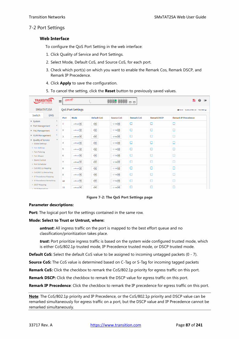
Transition Networks SMxTAT2SA Web User Guide
33717 Rev. A https://www.transition.com Page 87 of 241
7-2 Port Settings
Web Interface
To configure the QoS Port Setting in the web interface:
1. Click Quality of Service and Port Settings.
2. Select Mode, Default CoS, and Source CoS, for each port.
3. Check which port(s) on which you want to enable the Remark Cos, Remark DSCP, and
Remark IP Precedence.
4. Click Apply to save the configuration.
5. To cancel the setting, click the Reset button to previously saved values.
Figure 7-2: The QoS Port Settings page
Parameter descriptions:
Port: The logical port for the settings contained in the same row.
Mode: Select to Trust or Untrust, where:
untrust: All ingress traffic on the port is mapped to the best effort queue and no
classification/prioritization takes place.
trust: Port prioritize ingress traffic is based on the system wide configured trusted mode, which
is either CoS/802.1p trusted mode, IP Precedence trusted mode, or DSCP trusted mode.
Default CoS: Select the default CoS value to be assigned to incoming untagged packets (0 - 7).
Source CoS: The CoS value is determined based on C-Tag or S-Tag for incoming tagged packets
Remark CoS: Click the checkbox to remark the CoS/802.1p priority for egress traffic on this port.
Remark DSCP: Click the checkbox to remark the DSCP value for egress traffic on this port.
Remark IP Precedence: Click the checkbox to remark the IP precedence for egress traffic on this port.
Note: The CoS/802.1p priority and IP Precedence, or the CoS/802.1p priority and DSCP value can be
remarked simultaneously for egress traffic on a port, but the DSCP value and IP Precedence cannot be
remarked simultaneously.

Transition Networks SMxTAT2SA Web User Guide
33717 Rev. A https://www.transition.com Page 88 of 241
Buttons
Apply : Click to save changes.
Reset : Click to undo any changes made locally and revert to previously saved values.

Transition Networks SMxTAT2SA Web User Guide
33717 Rev. A https://www.transition.com Page 89 of 241
7-3 Port Policing
This section provides an overview of QoS Ingress Port Policers for all switch ports. Port Policing
is useful in constraining traffic flows and marking frames above specific rates. Policing is
primarily useful for data flows and voice or video flows because voice and video usually
maintains a steady rate of traffic.
Web Interface
To configure the QoS Port Policers in the web interface:
1. Click Quality of Service and Port Policing.
2. Click which port need to enable the QoS Ingress Port Policers, and configure the Rate
limit condition.
3. Click Apply to save the configuration.
4. To cancel the setting, click the Reset button to revert to previously saved values.
Figure 7-3: The QoS Ingress Port Policers page
Parameter descriptions:
Port: The logical port for the settings contained in the same row. Click on the port number to configure
its schedulers.
Enable: Check to enable for each Port you on which you want to enable the QoS Ingress Port Policers
function.
Rate (kbps): To set the Rate limit value for this port, the default is 1000000 kbps.
Buttons
Apply : Click to save changes.
Reset : Click to undo any changes made locally and revert to previously saved values.

Transition Networks SMxTAT2SA Web User Guide
33717 Rev. A https://www.transition.com Page 90 of 241
7-4 Port Shaper
This section provides an overview of QoS Egress Port Shapers for all switch ports.
Web Interface
To configure the QoS Port Shapers in the web interface:
1. Click Quality of Service and Port Shaper.
2. Select the port to configure QoS Egress Port Shaper.
3. Click the port to enable, and configure the Rate limit condition.
4. Click Apply to save the configuration.
5. To cancel the setting, click the Reset button to revert to previously saved values.
Figure 7-4: The QoS Egress Port Shaper page
Parameter descriptions:
Port : The logical port for the settings contained in the same row. Click on the port number to
configure the shapers.
Queue Shaper
Queue : The queue number of the queue shaper on this switch port.
Enable : Controls whether the queue shaper is enabled for this queue on this switch port.
Rate(kbps) : Controls the rate for the queue shaper. The default value is 1000000.
Port Shaper
Enable : Controls whether the port shaper is enabled for this switch port.
Rate(kbps) : Controls the rate for the port shaper. The default value is 1000000.

Transition Networks SMxTAT2SA Web User Guide
33717 Rev. A https://www.transition.com Page 91 of 241
Buttons
Apply : Click to save changes.
Reset : Click to undo any changes made locally and revert to previously saved values.
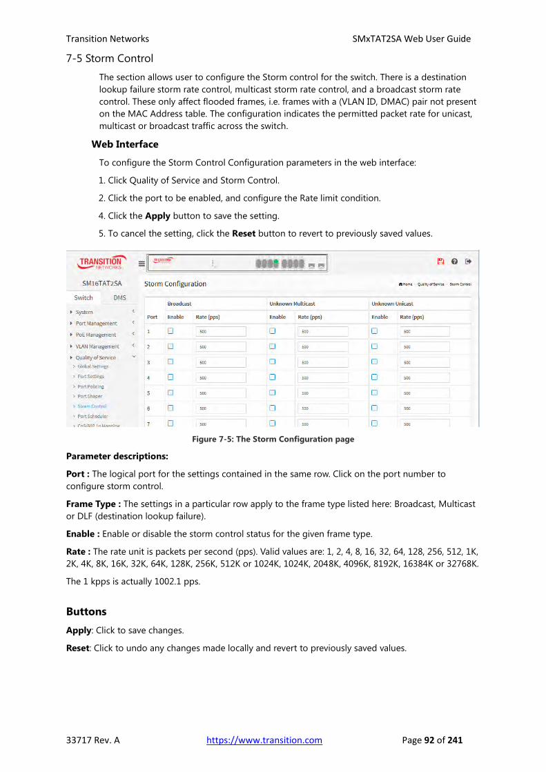
Transition Networks SMxTAT2SA Web User Guide
33717 Rev. A https://www.transition.com Page 92 of 241
7-5 Storm Control
The section allows user to configure the Storm control for the switch. There is a destination
lookup failure storm rate control, multicast storm rate control, and a broadcast storm rate
control. These only affect flooded frames, i.e. frames with a (VLAN ID, DMAC) pair not present
on the MAC Address table. The configuration indicates the permitted packet rate for unicast,
multicast or broadcast traffic across the switch.
Web Interface
To configure the Storm Control Configuration parameters in the web interface:
1. Click Quality of Service and Storm Control.
2. Click the port to be enabled, and configure the Rate limit condition.
4. Click the Apply button to save the setting.
5. To cancel the setting, click the Reset button to revert to previously saved values.
Figure 7-5: The Storm Configuration page
Parameter descriptions:
Port : The logical port for the settings contained in the same row. Click on the port number to
configure storm control.
Frame Type : The settings in a particular row apply to the frame type listed here: Broadcast, Multicast
or DLF (destination lookup failure).
Enable : Enable or disable the storm control status for the given frame type.
Rate : The rate unit is packets per second (pps). Valid values are: 1, 2, 4, 8, 16, 32, 64, 128, 256, 512, 1K,
2K, 4K, 8K, 16K, 32K, 64K, 128K, 256K, 512K or 1024K, 1024K, 2048K, 4096K, 8192K, 16384K or 32768K.
The 1 kpps is actually 1002.1 pps.
Buttons
Apply: Click to save changes.
Reset: Click to undo any changes made locally and revert to previously saved values.

Transition Networks SMxTAT2SA Web User Guide
33717 Rev. A https://www.transition.com Page 93 of 241
7-6 Port Scheduler
This section provides an overview of QoS Egress Port Scheduler for all switch ports.
Web Interface
To configure the QoS Port Schedulers in the web interface:
1. Click Quality of Service and Port Scheduler.
2. Select Scheduler Mode for each port.
3. If you select WRR (Weighted round robin) or WFQ (Weighted fair queueing), you can
configure weight.
4. Click the Apply button to save the setting.
5. To cancel the setting, click the Reset button to revert to previously saved values.
Figure 7-6: QoS Egress Port Scheduler
Parameter descriptions:
Port: The logical port for the settings contained in the same row.
Scheduler Mode: Controls whether the scheduler mode is "Strict Priority", "WRR" or
"WFQ" on this switch port.
WFQ allows specifying, for each flow, which fraction of the capacity will be given.
WRR serves a number of packets for each nonempty queue.
In a Strict Priority queue, an element with high priority is served before an element with low
priority.
If two elements have the same priority, they are served according to their order in the queue.
Weight: Controls the weight for this queue. The default value is "0". This value is restricted to 1-100.
This parameter is only shown if "Scheduler Mode" is set to "Weighted" (WRR or WFQ).
Buttons
Apply : Click to save changes.
Reset : Click to undo any changes made locally and revert to previously saved values.

Transition Networks SMxTAT2SA Web User Guide
33717 Rev. A https://www.transition.com Page 94 of 241
7-7 CoS/802.1p Mapping
Use the CoS/802.1p to Queue page to map 802.1p priorities to egress queues. The CoS/802.1p
to Queue table determines the egress queues of the incoming packets based on the 802.1p
priority in their VLAN tags. For incoming untagged packets, the 802.1p priority will be the
default CoS/802.1p priority assigned to the ingress ports.
Web Interface
To configure the Cos/802.1p Mapping in the web interface:
1. Click Quality of Service and Cos/802.1p Mapping.
2. Select a Queue ID.
3. Click the Apply button to save the setting.
4. To cancel the setting, click the Reset button to revert to previously saved values.
Figure 7-7: QoS Ingress CoS/802.1p to Queue Mapping
Parameter descriptions:
CoS/802.1p: Displays the 802.1p priority tag values to be assigned to an egress queue, where 0 is the
lowest and 7 is the highest priority.
Queue ID: Select the egress queue to which the 802.1p priority is mapped. Eight egress queues are
supported, where Queue 8 is the highest priority egress queue and Queue 1 is the lowest priority
egress queue.
Buttons
Apply : Click to save changes.
Reset : Click to undo any changes made locally and revert to previously saved values.

Transition Networks SMxTAT2SA Web User Guide
33717 Rev. A https://www.transition.com Page 95 of 241
7-8 CoS/802.1p Remarking
Use the Queues to CoS/802.1p page to remark the CoS/802.1p priority for egress traffic from
each queue.
Web Interface
To configure the Cos/802.1p Remarking in the web interface:
1. Click Quality of Service and Cos/802.1p Remarking.
2. Select CoS/802.1p.
3. Click the Apply button to save the setting.
4. To cancel the setting, click the Reset button to revert to previously saved values.
Figure 7-8: QoS Egress Queue to CoS/802.1p Remarking
Parameter descriptions:
Queue ID: Displays the Queue ID, where Queue 8 is the highest priority egress queue and Queue 1 is
the lowest priority egress queue.
CoS/802.1p: For each output queue, select the CoS/802.1p priority to which egress traffic from the
queue is remarked.
Buttons
Apply: Click to save changes.
Reset: Click to undo any changes made locally and revert to previously saved values.

Transition Networks SMxTAT2SA Web User Guide
33717 Rev. A https://www.transition.com Page 96 of 241
7-9 IP Precedence Mapping
This page lets you map an IP precedence to an egress queue.
Web Interface
To configure the IP Precedence Mapping in the web interface:
1. Click Quality of Service and IP Precedence Mapping.
2. Select Queue ID.
3. Click the Apply button to save the setting.
4. To cancel the setting, click the Reset button to revert to previously saved values.
Figure 7-9: QoS Ingress IP Precedence to Queue Mapping
Parameter descriptions:
IP Precedence: Displays the IP Precedence priority tag values to be assigned to an egress queue,
where 0 is the lowest and 7 is the highest priority.
Queue ID: Select the egress queue to which the IP precedence priority is mapped. Eight egress queues
are supported, where Queue 8 is the highest priority egress queue and Queue 1 is the lowest priority
egress queue.
Buttons
Apply: Click to save changes.
Reset: Click to undo any changes made locally and revert to previously saved values.

Transition Networks SMxTAT2SA Web User Guide
33717 Rev. A https://www.transition.com Page 97 of 241
7-10 IP Precedence Remarking
This page lets you map egress queue to IP precedence.
Web Interface
To configure the IP Precedence Remarking in the web interface:
1. Click Quality of Service and IP Precedence Remarking.
2. Select IP Precedence.
3. Click the Apply button to save the setting.
4. To cancel the setting, click the Reset button to revert to previously saved values.
Figure 7-10: QoS Egress Queue to IP Precedence Remarking
Parameter descriptions:
Queue ID: Displays the Queue ID, where Queue 8 is the highest priority egress queue and Queue 1 is
the lowest priority egress queue.
IP Precedence: For each output queue, select the IP Precedence priority to which egress traffic from
the queue is remarked.
Buttons
Apply: Click to save changes.
Reset: Click to undo any changes made locally and revert to previously saved values.
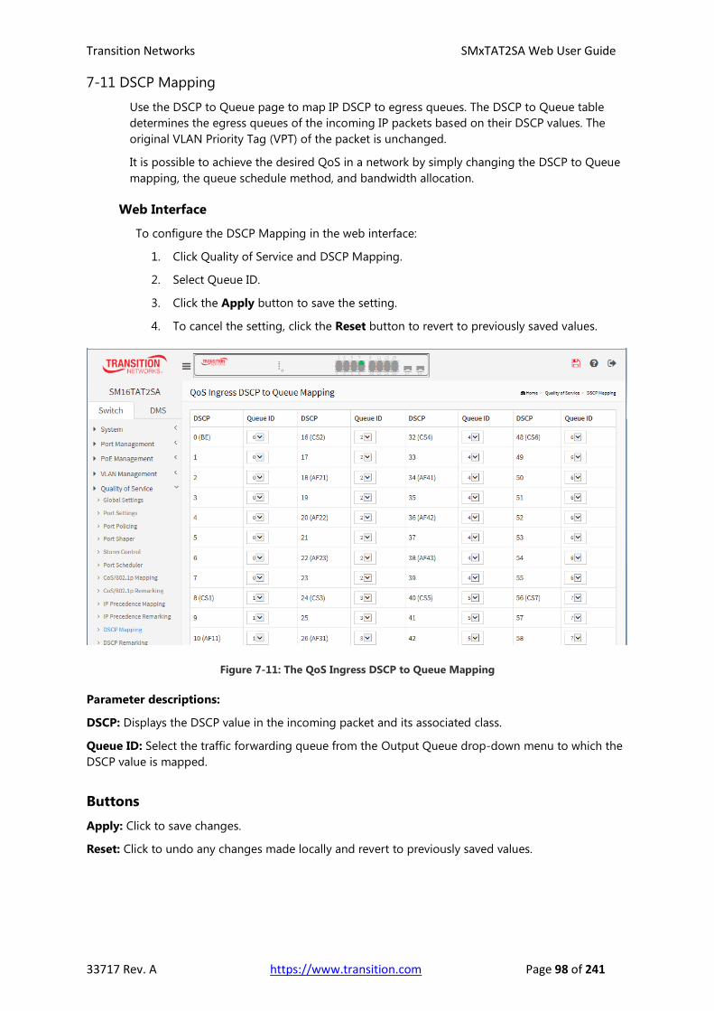
Transition Networks SMxTAT2SA Web User Guide
33717 Rev. A https://www.transition.com Page 98 of 241
7-11 DSCP Mapping
Use the DSCP to Queue page to map IP DSCP to egress queues. The DSCP to Queue table
determines the egress queues of the incoming IP packets based on their DSCP values. The
original VLAN Priority Tag (VPT) of the packet is unchanged.
It is possible to achieve the desired QoS in a network by simply changing the DSCP to Queue
mapping, the queue schedule method, and bandwidth allocation.
Web Interface
To configure the DSCP Mapping in the web interface:
1. Click Quality of Service and DSCP Mapping.
2. Select Queue ID.
3. Click the Apply button to save the setting.
4. To cancel the setting, click the Reset button to revert to previously saved values.
Figure 7-11: The QoS Ingress DSCP to Queue Mapping
Parameter descriptions:
DSCP: Displays the DSCP value in the incoming packet and its associated class.
Queue ID: Select the traffic forwarding queue from the Output Queue drop-down menu to which the
DSCP value is mapped.
Buttons
Apply: Click to save changes.
Reset: Click to undo any changes made locally and revert to previously saved values.

Transition Networks SMxTAT2SA Web User Guide
33717 Rev. A https://www.transition.com Page 99 of 241
7-12 DSCP Remarking
Use the Queues to DSCP page to remark DSCP value for egress traffic from each queue.
Web Interface
To configure the DSCP Remarking in the web interface:
1. Click Quality of Service and DSCP Remarking.
2. Select DSCP.
3. Click the Apply button to save the setting.
4. To cancel the setting, click the Reset button to revert to previously saved values.
Figure 7-12: The QoS Egress Queue to DSCP Remarking
Parameter descriptions:
Queue ID: Displays the Queue ID, where Queue 8 is the highest priority egress queue and
Queue 1 is the lowest priority egress queue.
DSCP: For each output queue, select the DSCP priority to which egress traffic from the
queue is remarked. For example Expedited Forwarding (EF) for low-loss, low-latency traffic
or Assured Forwarding (AF) which assures delivery under prescribed conditions.
Buttons
Apply: Click to save changes.
Reset: Click to undo any changes made locally and revert to previously saved values.

Transition Networks SMxTAT2SA Web User Guide
33717 Rev. A https://www.transition.com Page 100 of 241
Chapter 8 Spanning tree
The Spanning Tree Protocol (STP) can be used to detect and disable network loops, and to
provide backup links between switches, bridges or routers. This allows the switch to interact
with other bridging devices (that is, an STP-compliant switch, bridge or router) in your network
to ensure that only one route exists between any two stations on the network, and provide
backup links which automatically take over when a primary link goes down.
STP uses a distributed algorithm to select a bridging device (STP- compliant switch, bridge or
router) that serves as the root of the spanning tree network. It selects a root port on each
bridging device (except for the root device) which incurs the lowest path cost when forwarding
a packet from that device to the root device. Then it selects a designated bridging device from
each LAN which incurs the lowest path cost when forwarding a packet from that LAN to the
root device. All ports connected to designated bridging devices are assigned as designated
ports. After determining the lowest cost spanning tree, it enables all root ports and designated
ports, and disables all other ports. Network packets are therefore only forwarded between root
ports and designated ports, eliminating any possible network loops.
Figure 8: The Spanning Tree Protocol
Once a stable network topology has been established, all bridges listen for Hello BPDUs
(Bridge Protocol Data Units) transmitted from the Root Bridge. If a bridge does not get a Hello
BPDU after a predefined interval (Maximum Age), the bridge assumes that the link to the Root
Bridge is down. This bridge will then initiate negotiations with other bridges to reconfigure the
network to reestablish a valid network topology.

Transition Networks SMxTAT2SA Web User Guide
33717 Rev. A https://www.transition.com Page 101 of 241
8-1 State
The page lets you enable or disable MSTP; you can also select what protocol version you want.
The default is Spanning Tree enabled.
Web Interface
To configure the Spanning Tree Protocol version in the web interface:
1. Click Spanning Tree and state.
2. Select “on” to enable Spanning Tree Protocol.
3. Select the Spanning Tree Protocol version.
4. Click the Apply button to save the setting.
5. To cancel the setting, click the Reset button to revert to previously saved values.
Figure 8-1: The MSTP State page
Parameter descriptions:
Multiple Spanning Tree Protocol: You can select on to enable MSTP or off to disable MSTP.
Force Version: The STP protocol version setting. Valid values are STP, RSTP and MSTP.
Buttons
Apply: Click to save changes.
Reset: Click to undo any changes made locally and revert to previously saved values.
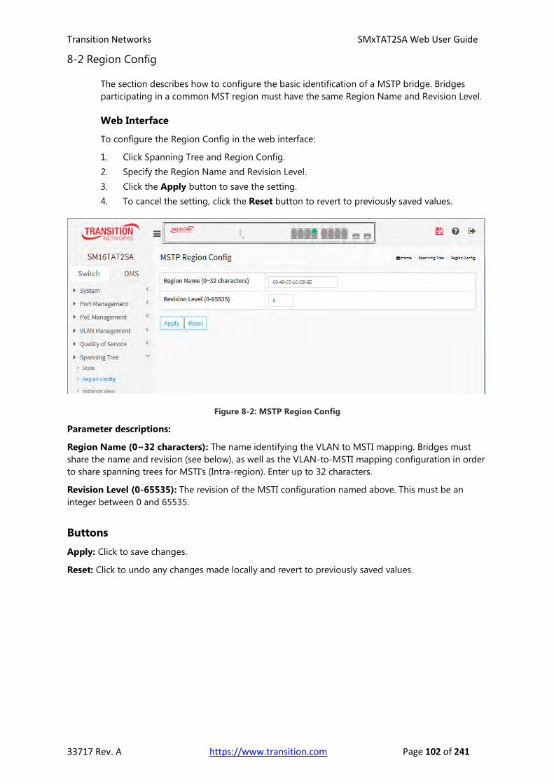
Transition Networks SMxTAT2SA Web User Guide
33717 Rev. A https://www.transition.com Page 102 of 241
8-2 Region Config
The section describes how to configure the basic identification of a MSTP bridge. Bridges
participating in a common MST region must have the same Region Name and Revision Level.
Web Interface
To configure the Region Config in the web interface:
1. Click Spanning Tree and Region Config.
2. Specify the Region Name and Revision Level.
3. Click the Apply button to save the setting.
4. To cancel the setting, click the Reset button to revert to previously saved values.
Figure 8-2: MSTP Region Config
Parameter descriptions:
Region Name (0~32 characters): The name identifying the VLAN to MSTI mapping. Bridges must
share the name and revision (see below), as well as the VLAN-to-MSTI mapping configuration in order
to share spanning trees for MSTI's (Intra-region). Enter up to 32 characters.
Revision Level (0-65535): The revision of the MSTI configuration named above. This must be an
integer between 0 and 65535.
Buttons
Apply: Click to save changes.
Reset: Click to undo any changes made locally and revert to previously saved values.

Transition Networks SMxTAT2SA Web User Guide
33717 Rev. A https://www.transition.com Page 103 of 241
8-3 Instance View
The section providing an MST instance table which include information(VLAN membership of a
MSTI ) of all spanning instances provisioned in the particular MST region which the bridge
belongs to. Through this table, additional MSTP configuration data can be applied and MSTP
status can be retrieved.
Web Interface
To configure the MSTP Instance in the web interface:
1. Click Spanning Tree and Instance View.
2. Click the Add Vlan button.
3. Specify the Instance and Port.
4. Click Instance Status and Port Status to see the detail.
5. To cancel the settings click the Delete button.
Figure 8-3: MSTP Instance Config
Parameter descriptions:
Instance ID: Every spanning tree instance need to have a unique instance ID within 0~4095. Instance 0
(CIST) always exists and cannot be deleted. Additional spanning instances (MSTIs) can be added or
deleted. At least one VLAN must be provisioned for an MSTI to declare the need for the MSTI to exist.
Corresponding Vlans: 0-4095. Multiple VLANs can belong to an MSTI. All VLANs that are not
provisioned through this will be automatically assigned to Instance 0 (CIST).
Buttons
Add Vlan: To add an MSTI and provide its VLAN members or modify VLAN members for a specific
MSTI, you can add up to 63 to a total of 64.
Delete: To delete an MSTI.
Instance Config: To provision spanning tree performance parameters per instance.
Port Config: To provision spanning tree performance parameters per instance per port.
Instance Status: To show the status report of a particular spanning tree instance.
Port Status: To show the status report of all ports regarding a specific spanning tree instance.
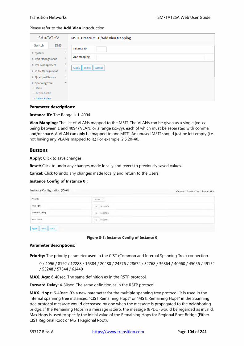
Transition Networks SMxTAT2SA Web User Guide
33717 Rev. A https://www.transition.com Page 104 of 241
Please refer to the Add Vlan introduction:
Parameter descriptions:
Instance ID: The Range is 1-4094.
Vlan Mapping: The list of VLANs mapped to the MSTI. The VLANs can be given as a single (xx, xx
being between 1 and 4094) VLAN, or a range (xx-yy), each of which must be separated with comma
and/or space. A VLAN can only be mapped to one MSTI. An unused MSTI should just be left empty (i.e.,
not having any VLANs mapped to it.) For example: 2,5,20-40.
Buttons
Apply: Click to save changes.
Reset: Click to undo any changes made locally and revert to previously saved values.
Cancel: Click to undo any changes made locally and return to the Users.
Instance Config of Instance 0 :
Figure 8-3: Instance Config of Instance 0
Parameter descriptions:
Priority: The priority parameter used in the CIST (Common and Internal Spanning Tree) connection.
0 / 4096 / 8192 / 12288 / 16384 / 20480 / 24576 / 28672 / 32768 / 36864 / 40960 / 45056 / 49152
/ 53248 / 57344 / 61440
MAX. Age: 6-40sec. The same definition as in the RSTP protocol.
Forward Delay: 4-30sec. The same definition as in the RSTP protocol.
MAX. Hops: 6-40sec. It’s a new parameter for the multiple spanning tree protocol. It is used in the
internal spanning tree instances. “CIST Remaining Hops” or “MSTI Remaining Hops” in the Spanning
tree protocol message would decreased by one when the message is propagated to the neighboring
bridge. If the Remaining Hops in a message is zero, the message (BPDU) would be regarded as invalid.
Max Hops is used to specify the initial value of the Remaining Hops for Regional Root Bridge (Either
CIST Regional Root or MSTI Regional Root).

Transition Networks SMxTAT2SA Web User Guide
33717 Rev. A https://www.transition.com Page 105 of 241
Buttons
Apply : Click to save changes.
Reset : Click to undo any changes made locally and revert to previously saved values.
Back : Click to undo any changes made locally and return to the Users.
Port Config of Instance 0 :
Figure 8-3: Port Config of Instance 0
Parameter descriptions:
Port: The logical port for the settings contained in the same row.
Path Cost: 1 – 200,000,000. The same definition as in the RSTP specification. But in MSTP, this
parameter can be respectively applied to ports of CIST and ports of any MSTI.
Priority: 0 / 16 / 32 / 48 / 64 / 80 / 96 / 112 / 128 / 144 / 160 / 176 / 192 / 208 / 224 / 240 . The same
definition as in the RSTP specification. But in MSTP, this parameter can be respectively applied to ports
of CIST and ports of any MSTI.
Admin Edge: Yes / No. The same definition as in the RSTP specification for the CIST ports. The factory
default setting is No (Non-Edge).
Admin P2P: Auto / True / False. The same definition as in the RSTP specification for the CIST ports.
Restricted Role: Yes / No. If “Yes” causes the Port not to be selected as Root Port for the CIST or any
MSTI, even it has the best spanning tree priority vector. Such a Port will be selected as an Alternate Port
after the Root Port has been selected. This parameter is “No” by default. If set, it can cause lack of
spanning tree connectivity. It is set by a network administrator to prevent bridges external to a core
region of the network influencing the spanning tree active topology, possibly because those bridges
are not under the full control of the administrator.
Restricted TCN: Yes / No. If “Yes” causes the Port not to propagate received topology change
notifications and topology changes to other Ports. This parameter is “No” by default. If set it can cause
temporary loss of connectivity after changes in a spanning trees active topology as a result of
persistent incorrectly learned station location information. It is set by a network administrator to
prevent bridges external to a core region of the network, causing address flushing in that region,
possibly because those bridges are not under the full control of the administrator, or the status of MAC
operation for the attached LANs transitions frequently.
Mcheck: The same definition as in the RSTP specification for the CIST ports. The STP mCheck
(Migration Check) variable. Automatically migrate from RSTP or MSTP to STP-compatible mode.
Buttons
Apply : Click to save changes.
Back : Click to undo any changes made locally and return to the Users.

Transition Networks SMxTAT2SA Web User Guide
33717 Rev. A https://www.transition.com Page 106 of 241
Instance Status of Instance 0 :
Figure 8-3: Instance Status of Instance 0
Parameter descriptions:
MSTP State : MSTP protocol is Enable or Disable.
Force Version : Shows the current spanning tree protocol version configured.
Bridge Max Age : Shows the Max Age setting of the bridge itself.
Bridge Forward Delay : Shows the Forward Delay setting of the bridge itself.
Bridge Max Hops : Shows the Max Hops setting of the bridge itself.
Instance Priority : Spanning tree priority value for a specific tree instance(CIST or MSTI)
Bridge Mac Address : The Mac Address of the bridge itself.
CIST ROOT PRIORITY : Spanning tree priority value of the CIST root bridge
CIST ROOT MAC : Mac Address of the CIST root bridge
CIST EXTERNAL ROOT PATH COST : Root path cost value from the point of view of the bridge’s MST
region.
CIST ROOT PORT ID : The port ID of the bridge’s root port. In MSTP, peer port of a root port may
reside in different MST region or in the same MST region. The first case indicates that the root port’s
owner is the CIST regional root bridge.
CIST REGIONAL ROOT PRIORITY: Spanning tree priority value of the CIST regional root bridge. Note
that CIST Regional Root bridge is different from CIST Root bridge. One exception is that when a bridge
belonging to an MST region happens to be the root bridge of the CST (Common Spanning Tree). An
MST Region in the CST can be regarded as a common RSTP bridge. The IST (Internal Spanning Tree)
and MSTIs are transparent to bridges outside this region.
CIST REGIONAL ROOT MAC : Mac Address of the CIST regional root bridge.
CIST INTERNAL ROOT PATH COST : Root path cost value from the point of view of the bridges inside
the IST.
CIST CURRENT MAX AGE : Max Age of the CIST Root bridge.
CIST CURRENT FORWARD DELAY : Forward Delay of the CIST Root bridge.

Transition Networks SMxTAT2SA Web User Guide
33717 Rev. A https://www.transition.com Page 107 of 241
TIME SINCE LAST TOPOLOGY CHANGE(SECs) : Time Since Last Topology Change is the elapsed time
in unit of seconds for a bunch of “Topology Change and(or) Topology Change Notification receiving” to
occur. When new series of Topology Changes occur again, this counter will be reset to 0.
TOPOLOGY CHANGE COUNT(SECs) : The per spanning tree instance Topology Change Count
expresses the time spent in unit of seconds since the beginning of the Spanning Tree Topology Change
to the end of the STP convergence. Once there is no topology change occurring and no more topology
change notification received, the Topology Change count will be reset to 0.
Buttons
Back : Click to undo any changes made locally and return to the Users page.
Refresh : Click to refresh the page.

Transition Networks SMxTAT2SA Web User Guide
33717 Rev. A https://www.transition.com Page 108 of 241
Port Status of Instance 0 :
Figure 8-3: Port Status of Instance 0
Parameter descriptions:
Port No: The port number to which the configuration applies.
Status: The forwarding status. Same definition as of the RSTP specification Possible values are
“FORWARDING”, “LEARNING”, “DISCARDING”.
Role: The role that a port plays in the spanning tree topology. Possible values are “disable”(disable
port) , ”alternate”(alternate port) , “backup”(backup port) , “ROOT”(root port) , “DSGN”(designated
port) , “MSTR”(master port). The last 3 are possible port roles for a port to transit to FORWARDING
state
Path Cost: Display currently resolved port path cost value for each port in a particular spanning tree
instance.
Priority: Display port priority value for each port in a particular spanning tree instance.
Hello: Per port Hello Time display. It takes the following form: Current Hello Time/Hello Time Setting
Oper. Edge: Whether or not a port is actually an Edge Port.
Oper. P2P: Whether or not a port is actually a Point-to-Point port.
Restricted Role: Same as mentioned in “Port Config”.
Restricted Tcn: Same as mentioned in “Port Config”.
Buttons
Back : Click to undo any changes made locally and return to the Users.
Refresh : Click to refresh the page.
Messages
Message: MSTP disabled or force version is not MSTP.
Recovery: Click OK to clear, change the Instance Status parameter, and continue.
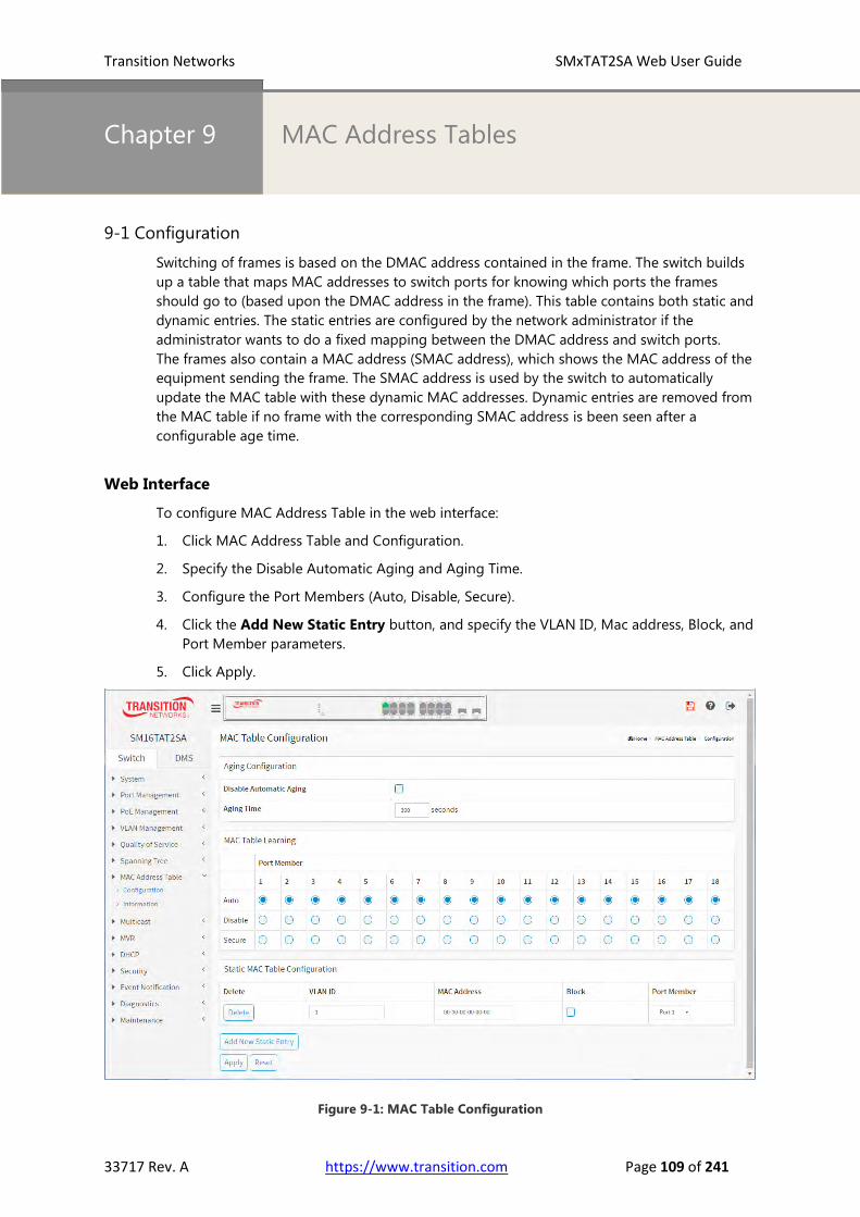
Transition Networks SMxTAT2SA Web User Guide
33717 Rev. A https://www.transition.com Page 109 of 241
Chapter 9 MAC Address Tables
9-1 Configuration
Switching of frames is based on the DMAC address contained in the frame. The switch builds
up a table that maps MAC addresses to switch ports for knowing which ports the frames
should go to (based upon the DMAC address in the frame). This table contains both static and
dynamic entries. The static entries are configured by the network administrator if the
administrator wants to do a fixed mapping between the DMAC address and switch ports.
The frames also contain a MAC address (SMAC address), which shows the MAC address of the
equipment sending the frame. The SMAC address is used by the switch to automatically
update the MAC table with these dynamic MAC addresses. Dynamic entries are removed from
the MAC table if no frame with the corresponding SMAC address is been seen after a
configurable age time.
Web Interface
To configure MAC Address Table in the web interface:
1. Click MAC Address Table and Configuration.
2. Specify the Disable Automatic Aging and Aging Time.
3. Configure the Port Members (Auto, Disable, Secure).
4. Click the Add New Static Entry button, and specify the VLAN ID, Mac address, Block, and
Port Member parameters.
5. Click Apply.
Figure 9-1: MAC Table Configuration

Transition Networks SMxTAT2SA Web User Guide
33717 Rev. A https://www.transition.com Page 110 of 241
Parameter descriptions:
Aging Configuration: By default, dynamic entries are removed from the MAC table after 300 seconds.
This removal is also called aging.
Configure aging time by entering a value here in seconds. The valid range is 10 - 1000000 seconds.
Disable the automatic aging of dynamic entries by checking Disable automatic aging.
MAC Table Learning
If the learning mode for a given port is greyed out, another module is in control of the mode, so that it
cannot be changed by the user. An example of such a module is the MAC-Based Authentication under
802.1X. Each port can do learning based upon the following settings:
Auto: Learning is done automatically as soon as a frame with unknown SMAC is received.
Disable: No learning is done.
Secure: Only static MAC entries are learned, all other frames are dropped.
NOTE: Make sure that the link used for managing the switch is added to the Static
MAC Table before changing to secure learning mode, otherwise the management
link is lost and can only be restored by using another non-secure port or by
connecting to the switch via the Telnet interface.
Static MAC Table Configuration
The static entries in the MAC table are shown in this table. The static MAC table can contain 64 entries.
The MAC table is sorted first by VLAN ID and then by MAC address.
Delete: Check to delete the entry. It will be deleted during the next save.
VLAN ID: The VLAN ID of the entry.
MAC Address: The MAC address of the entry.
Block: Click it, if you want block this mac address.
Port Members: Checkmarks indicate which ports are members of the entry. Check or uncheck as
needed to modify the entry.
Buttons
Add New Static Entry: Click to add a new entry to the static MAC table. Specify the VLAN ID, MAC
address, and port members for the new entry. Click "Apply".
Apply: Click to save changes.
Reset: Click to undo any changes made locally and revert to previously saved values.

Transition Networks SMxTAT2SA Web User Guide
33717 Rev. A https://www.transition.com Page 111 of 241
9-2 Information
Entries in the MAC Table are shown on this page. The MAC Table contains up to 8192 entries,
and is sorted first by VLAN ID, then by MAC address.
Web Interface
To display the Dynamic MAC Table in the web interface:
1. Click MAC Address Table and Information.
2. View the displayed MAC Address Table.
Figure 9-2: Dynamic MAC Table
Parameter descriptions:
Navigating the MAC Table
Show x entries: At the dropdown, select how many lines to display per page (10, 25, 60, 100, or 500).
Type: Indicates whether the entry is a static or a dynamic entry, 802.1x, DMS.
VLAN: The VLAN ID of the entry.
MAC address: The MAC address of the entry.
Block: Whether the mac address is blocked or not.
Port Members: The ports that are members of the entry.
Buttons
Auto-refresh: Check this box to refresh the page automatically every 3 seconds.
Refresh: Click to refresh the page.
Clear: Click to clear the page.
Next : Updates the system log entries, turn to the next page.
Previous : Updates the system log entries, turn to the previous page.
NOTE:
00-40-C7-73-01-29 : your switch MAC address (for IPv4)
33-33-00-00-00-01 : Destination MAC (for IPv6 Router Advertisement) (reference IPv6 RA.JPG)
33-33-00-00-00-02 : Destination MAC (for IPv6 Router Solicitation) (reference IPv6 RS.JPG)
33-33-FF-73-01-29 : Destination MAC (for IPv6 Neighbor Solicitation) (reference IPv6 DAD.JPG)
33-33-FF-A8-01-01: your switch MAC address (for IPv6 global IP)
FF-FF-FF-FF-FF-FF: for Broadcast.

115
Chapter 10 Multicast
10-1 IGMP Snooping
This function is used to establish the multicast groups to forward the
multicast packet to the member ports, and, in nature, avoids wasting the
bandwidth while IP multicast packets are running over the network. This is
because a switch that does not support IGMP or IGMP Snooping cannot
tell a multicast packet from a broadcast packet, so it can only treat them all
as a broadcast packet. Without IGMP Snooping, a multicast packet
forwarding function is plain and nothing is different from a broadcast
packet.
The switch supports IGMP Snooping with the functions of query, report
and leave, a type of packet exchanged between IP Multicast Router/Switch
and IP Multicast Host, can update the information of the Multicast table
when a member (port) joins or leaves an IP Multicast Destination Address.
With this function, once a switch receives an IP multicast packet, it will
forward the packet to the members who joined in a specified IP multicast
group before.
The packets will be discarded by the IGMP Snooping if the user transmits multicast packets to
the multicast group that had not been built up in advance. IGMP mode enables the switch to
issue IGMP function that you enable IGMP proxy or snooping on the switch, which connects to
a router closer to the root of the tree. This interface is the upstream interface. The router on
the upstream interface should be running IGMP.
10-1.1 Basic Configuration
The section describes how to set the basic IGMP snooping on the switch, which connects to a
router closer to the root of the tree. This interface is the upstream interface. The router on the
upstream interface should be running IGMP.
Web Interface
To configure the IGMP Snooping parameters in the web interface:
1. Click Multicast, IGMP Snooping, and Basic Configuration.
2. Enable or disable which Global configuration.
3. Select the port you want to become a Router Port or enable/ disable the Fast Leave
function.
4. Scroll to set the Throtting and Profile.
5. Click the Apply button to save the setting.
6. To cancel the setting, click the Reset button to revert to previously saved values.

Transition Networks SMxTAT2SA Web User Guide
33717 Rev. A https://www.transition.com Page 113 of 241
Figure 10-1.1: IGMP Snooping Configuration
Parameter descriptions:
Global Configuration
Snooping Enabled: Enable the Global IGMP Snooping.
Unregistered IPMCv4 Flooding enabled: Enable unregistered IPMCv4 traffic flooding.
IGMP SSM Range: SSM (Source-Specific Multicast) Range lets the SSM-aware hosts and routers run
the SSM service model for the groups in the address range. Format: (IP address/ sub mask).
Per IETF RFC 4607, IP version 4 (IPv4) addresses in the 232/8 (232.0.0.0 to232.255.255.255) range are
designated as source-specific multicast (SSM) destination addresses and are reserved for use by
source-specific applications and protocols. For IP version 6 (IPv6), the address prefix FF3x::/32 is
reserved for source-specific multicast use.
Proxy Enabled: Enable IGMP Proxy. This feature can be used to avoid forwarding unnecessary join and
leave messages to the router side.
Port Related Configuration
Port: It shows the physical Port index of switch.
Router Port: Specify which ports act as router ports. A router port is a port on the Ethernet switch that
leads towards the Layer 3 multicast device or IGMP querier. If an aggregation member port is selected
as a router port, the whole aggregation will act as a router port.
Fast Leave: Enable the fast leave on the port.
Throttling: Enable to limit the number of multicast groups to which a switch port can belong.
Profile: You can select profile when you edit in Multicast Filtering Profile.
Buttons
Apply : Click to save changes.
Reset : Click to undo any changes made locally and revert to previously saved values.

Transition Networks SMxTAT2SA Web User Guide
33717 Rev. A https://www.transition.com Page 114 of 241
10-1.2 VLAN Configuration
The section describes the VLAN configuration setting process integrated with IGMP Snooping
function. Each page shows up to 99 entries from the VLAN table, default being 20, selected
through the "entries per page" input field. When first visited, the web page will show the first
20 entries from the beginning of the VLAN Table. The first displayed will be the one with the
lowest VLAN ID found in the VLAN Table. The "VLAN" input fields allow the user to select the
starting point in the VLAN Table.
Web Interface
To configure the IGMP Snooping VLAN Configuration in the web interface:
1. Click Multicast, IGMP Snooping, and VLAN Configuration.
2. Click the Add New IGMP VLAN button to add a new row to the table.
3. Click the Apply button to save the setting.
4. To cancel the setting, click the Reset button to revert to previously saved values.
Figure 10-1.2: IGMP Snooping VLAN Configuration
Parameter descriptions:
Start from Vlan: Click to refresh the displayed table starting from the "VLAN" input fields.
Delete: Check to delete the entry. The designated entry will be deleted during the next save.
VLAN ID: Displays the VLAN ID (VID) of the entry.
Snooping Enabled: Enable the per-VLAN IGMP Snooping. Only up to 32 VLANs can be selected. .
IGMP Querier: Enable to join IGMP Querier election in the VLAN. Disable to act as an IGMP
Non-Querier.
Compatibility: Compatibility is maintained by hosts and routers taking appropriate
actions depending on the versions of IGMP operating on hosts and routers within a
network. The allowed selections are IGMP-Auto, Forced IGMPv1, Forced IGMPv2, Forced
IGMPv3. The default is IGMP-Auto.
IGMP v1 is specified in RFC-1112; it was the first widely-deployed version and the first version to
become an Internet Standard.
IGMP v2, specified in RFC-2236, added the ability for a host to signal desire to leave a multicast group.
IGMP v3, specified in RFC 3376, adds support for "source filtering", that is, the ability for a system to
report interest in receiving packets *only* from specific source addresses, or from *all but* specific
source addresses, sent to a particular multicast address.

Transition Networks SMxTAT2SA Web User Guide
33717 Rev. A https://www.transition.com Page 115 of 241
Rv: Robustness Variable. The Robustness Variable allows tuning for the expected packet loss on a
network. The allowed range is 1 to 255; default RV value is 2.
QI(sec): Query Interval. The Query Interval is the interval between General Queries sent by the Querier.
The allowed range is 1 to 31744 seconds; default query interval is 125 seconds.
QRI(0.1 sec): Query Response Interval. The Max Response Time used to calculate the Max Resp Code
inserted into the periodic General Queries. The allowed range is 0 to 31744 in tenths of seconds;
default query response interval is 100 in tenths of seconds (10 seconds).
LLQI (0.1 sec): Last Member Query Interval. The Last Member Query Time is the time value
represented by the Last Member Query Interval, multiplied by the Last Member Query Count.
The allowed range is 0 to 31744 in tenths of seconds; the default last member query interval is 10 in
tenths of seconds (1 second).
URI(sec): Unsolicited Report Interval. The Unsolicited Report Interval is the time between repetitions of
a host's initial report of membership in a group. The allowed range is 0 to 31744 seconds, default
unsolicited report interval is 1 second.
Buttons
Apply: Click to save changes.
Reset: Click to undo any changes made locally and revert to previously saved values.

Transition Networks SMxTAT2SA Web User Guide
33717 Rev. A https://www.transition.com Page 116 of 241
10-1.3 Status
After you complete the IGMP Snooping configuration, you can view the IGMP Snooping
Status. This page displays the IGMP Snooping detail status.
Web Interface
To display the IGMP Snooping status in the web interface:
1. Click Multicast, IGMP Snooping, and Status.
2. To auto-refresh the information, set “Auto-refresh” to On.
3. Click “Refresh” to refresh the IGMP Snooping Status.
Figure 10-1.3: IGMP Snooping Status
Parameter descriptions:
Statistics
VLAN ID: The VLAN ID of the entry.
Querier Version: Working Querier Version currently.
Host Version: Working Host Version currently.
Querier Status: Shows the Querier status is "ACTIVE" or "IDLE". "DISABLE" denotes the specific
interface is administratively disabled.
Queries Transmitted: The number of Transmitted Queries.
Queries Received: The number of Received Queries.
V1 Reports Received: The number of Received V1 Reports.
V2 Reports Received: The number of Received V2 Reports.
V3 Reports Received: The number of Received V3 Reports.
V2 Leaves Received: The number of Received V2 Leaves.

Transition Networks SMxTAT2SA Web User Guide
33717 Rev. A https://www.transition.com Page 117 of 241
Router Port: Displays which ports act as router ports. A router port is a port on the Ethernet switch
that leads towards the Layer 3 multicast device or IGMP querier. Static denotes the specific port is
configured to be a router port. Dynamic denotes the specific port is learnt to be a router port. Both
denote the specific port is configured or learnt to be a router port.
Port: Switch port number.
Status: Indicate whether specific port is a router port or not.
Buttons
Auto-refresh: Check this box to refresh the page automatically every 3 seconds.
Refresh: Click to refresh the page immediately.

Transition Networks SMxTAT2SA Web User Guide
33717 Rev. A https://www.transition.com Page 118 of 241
10-1.4 Group Information
After you complete setting the IGMP Snooping function, you can view the IGMP Snooping
Group Information. Entries in the IGMP Group Table are shown on this page. The IGMP Group
Table is sorted first by VLAN ID, and then by group. When the end is reached the text "No more
entries" is shown in the displayed table.
Group Member Behavior: in order to be compatible with older version routers, IGMPv3 hosts
must operate in version 1 and version 2 compatibility modes. IGMPv3 hosts MUST keep state
per local interface regarding the compatibility mode of each attached network. A host's
compatibility mode is determined from the Host Compatibility Mode variable which can be in
one of three states: IGMPv1, IGMPv2 or IGMPv3. This variable is kept per interface and
depends on the version of General Queries heard on that interface as well as the older querier
present timers for the interface.
Web Interface
To display the IGMP Snooping Group Information in the web interface:
1. Click Multicast, IGMP Snooping, and Group Information.
2. Specify how many entries to show in one page.
3. To auto-refresh the information click the “Auto-refresh” button.
4. Click “Refresh” to refresh an entry of the IGMP Snooping Groups Information.
5. Click Previous or Next to change pages.
Figure 10-1.4: IGMP Snooping Groups Information
Parameter descriptions:
Navigating the IGMP Group Table
Each page shows up to 99 entries from the IGMP Group table, default being 20, selected through the
"entries per page" input field. When first visited, the web page shows the first 20 entries from the
beginning of the IGMP Group Table. The "Start from VLAN", and "group" input fields let you select the
starting point in the IGMP Group Table.
Search: You can search for the information that you want to see.
Show entries: You can choose how many items you want to view.
VLAN ID: VLAN ID of the group.
Groups: Group address of the group displayed.
Port Members: Ports under this group.
Buttons
Auto-refresh : Check this box to refresh the page automatically every 3 seconds.
Refresh : Click to refresh the page immediately.
Next : Updates the system log entries, turn to the next page.
Previous : Updates the system log entries, turn to the previous page.

Transition Networks SMxTAT2SA Web User Guide
33717 Rev. A https://www.transition.com Page 119 of 241
10-1.5 IGMP SFM Information
Entries in the IGMP SFM Information Table are shown on this page. The IGMP SFM
(Source-Filtered Multicast) Information Table also contains the SSM (Source-Specific Multicast)
information. This table is sorted first by VLAN ID, then by group, and then by Port. Different
source addresses belong to the same group are treated as single entry.
Web Interface
To display the IGMP SFM Information in the web interface:
1. Click Multicast, IGMP Snooping, and IGMP SFM Information.
2. To auto-refresh the information select “Auto-refresh”.
3. Click “Refresh” to refresh an entry of the IGMP Snooping Groups Information.
4. Click Previous/Next to change page.
Figure 10-1.5: IGMP SFM Information
Navigating the IGMP SFM Information Table
Each page shows up to 99 entries from the IGMP SFM Information table, default being 20, selected
through the "entries per page" input field. When first visited, the web page will show the first 20 entries
from the beginning of the IGMP SFM Information Table.
The "Start from VLAN", and "group" input fields allow the user to select the starting point in the IGMP
SFM Information Table. Clicking the Next button will update the displayed table starting from that or
the closest next IGMP SFM Information Table match. In addition, the two input fields will - upon a
Previous button click - assume the value of the first displayed entry, allowing for continuous refresh
with the same start address.
Parameter descriptions:
Search : You can search for the information that you want to see.
Show entries : You can choose how many items you want to show.
VLAN ID : VLAN ID of the group.
Group : Group address of the group displayed.
Port : Switch port number.
Mode : Indicates the filtering mode maintained per (VLAN ID, port number, Group Address) basis. It
can be either Include or Exclude.
Source Address : IP Address of the source. Currently, system limits the total number of IP source
addresses for filtering to be 128.
Type : Indicates the Type. It can be either Allow or Deny.

Transition Networks SMxTAT2SA Web User Guide
33717 Rev. A https://www.transition.com Page 120 of 241
Buttons
Auto-refresh : Check this box to refresh the page automatically every 3 seconds.
Refresh : Click to refresh the page immediately.
Next : Updates the system log entries, turn to the next page.
Previous : Updates the system log entries, turn to the previous page.

Transition Networks SMxTAT2SA Web User Guide
33717 Rev. A https://www.transition.com Page 121 of 241
10-2 MLD Snooping
Curiously enough, a network node that acts as a source of IPv6 multicast traffic is only an
indirect participant in MLD snooping - it just provides multicast traffic, and MLD doesn’t
interact with it. (Note, however, that in an application like desktop conferencing a network
node may act as both a source and an MLD host; but MLD interacts with that node only in its
role as an MLD host.)
A source node creates multicast traffic by sending packets to a multicast address. In IPv6,
addresses with the first eight bits set (that is, “FF” as the first two characters of the address) are
multicast addresses, and any node that listens to such an address will receive the traffic sent to
that address. Application software running on the source and destination systems cooperates
to determine what multicast address to use. (Note that this is a function of the application
software, not of MLD.)
When MLD snooping is enabled on a VLAN, the switch acts to minimize unnecessary multicast
traffic. If the switch receives multicast traffic destined for a given multicast address, it forwards
that traffic only to ports on the VLAN that have MLD hosts for that address. It drops that traffic
for ports on the VLAN that have no MLD hosts.
Figure 10-2: MLD Snooping enabled
10-2.1 Basic Configuration
The section let you configure the MLD Snooping basic configuration and the parameters.
Web Interface
To configure the MLD Snooping Configuration in the web interface:
1. Click Multicast, MLD Snooping, and Basic Configuration.
2. Select “on” to enable Snooping globally and configure the parameters.
3. Select the port to join Router Port and Fast Leave.
4. Scroll to the Throtting mode dropdown and select unlimited or 1 to 10.
5. Click the Save button to save the settings.
6. To cancel the settings, click the Reset button to revert to previously saved values.

Transition Networks SMxTAT2SA Web User Guide
33717 Rev. A https://www.transition.com Page 122 of 241
Figure 10-2.1: MLD Snooping Basic Configuration
Parameter descriptions:
Global Configuration
Snooping Enabled : Enable the Global MLD Snooping.
Unregistered IPMCv6 Flooding enabled : Enable unregistered IPMCv6 traffic flooding.
Flooding control takes effect only when MLD Snooping is enabled. When MLD Snooping is disabled,
then unregistered IPMCv6 traffic flooding is always active in spite of this setting.
MLD SSM Range : SSM (Source-Specific Multicast) Range allows the SSM-aware hosts and routers run
the SSM service model for the groups in the address (using IPv6 Address) range.
Proxy Enabled : Enable MLD Proxy. This feature can be used to avoid forwarding unnecessary join and
leave messages to the router side.
Port Related Configuration
Router Port : Specify which ports act as router ports. A router port is a port on the Ethernet switch that
leads towards the Layer 3 multicast device or MLD querier. If an aggregation member port is selected
as a router port, the whole aggregation will act as a router port.
Fast Leave : Check the box to enable Fast Leave on the port.
Throttling : Enable to limit the number of multicast groups to which a switch port can belong.
Profile : You can select profile when you edit in Multicast Filtering Profile.
Buttons
Apply : Click to save changes.
Reset : Click to undo any changes made locally and revert to previously saved values.

Transition Networks SMxTAT2SA Web User Guide
33717 Rev. A https://www.transition.com Page 123 of 241
10-2.2 VLAN Configuration
When MLD snooping is enabled on a VLAN, the switch acts to minimize unnecessary multicast
traffic. If the switch receives multicast traffic destined for a given multicast address, it forwards
that traffic only to ports on the VLAN that have MLD hosts for that address. It drops that traffic
for ports on the VLAN that have no MLD hosts
The will use the last entry of the currently displayed entry as a basis for the next lookup. When
the end is reached the text "No more entries" is shown in the displayed table. Use the Reset
button to start over.
Web Interface
To configure the MLD Snooping VLAN Configuration in the web interface:
1. Click Multicast, MLD Snooping and VLAN Configuration.
2. Click Add New MLD VLAN.
3. Specify the VLAN ID with entries per page.
Figure 10-2.2: MLD Snooping VLAN Configuration
Parameter descriptions:
Delete: Check to delete the entry. The designated entry will be deleted during the next save.
VLAN ID: It displays the VLAN ID of the entry.
Snooping Enabled: Enable the per-VLAN IGMP Snooping. Up to 32 VLANs can be selected.
MLD Querier: Enable to join IGMP Querier election in the VLAN. Disable to act as an IGMP
Non-Querier.
Compatibility: Compatibility is maintained by hosts and routers taking appropriate actions
depending on the versions of IGMP operating on hosts and routers within a network. The
allowed selections are MLD-Auto, Forced MLD v1, Forced MLD v2. The default compatibility
value is MLD-Auto.
RV: Robustness Variable. The Robustness Variable allows tuning for the expected packet loss on a
network. The allowed range is 1 to 255; the default robustness variable value is 2.
QI(sec): Query Interval. The Query Interval is the interval between General Queries sent by the Querier.
The allowed range is 1 to 31744 seconds; the default query interval is 125 seconds.
QRI(0.1sec): Query Response Interval. The Max Response Time used to calculate the Max Resp Code
inserted into the periodic General Queries. The allowed range is 0 to 31744 in tenths of seconds;
default query response interval is 100 in tenths of seconds (10 seconds).

Transition Networks SMxTAT2SA Web User Guide
33717 Rev. A https://www.transition.com Page 124 of 241
LLQI (LMQI for IGMP): Last Member Query Interval. The Last Member Query Time is the time value
represented by the Last Member Query Interval, multiplied by the Last Member Query Count. The
allowed range is 0 to 31744 in tenths of seconds; default last member query interval is 10 in tenths of
seconds (1 second).
URI(sec): Unsolicited Report Interval. The Unsolicited Report Interval is the time between repetitions of
a host's initial report of membership in a group. The allowed range is 0 to 31744 seconds, default
unsolicited report interval is 1 second.
Buttons
Apply: Click to save changes.
Reset: Click to undo any changes made locally and revert to previously saved values.

Transition Networks SMxTAT2SA Web User Guide
33717 Rev. A https://www.transition.com Page 125 of 241
10-2.3 Status
The section describes when you complete the MLD Snooping and how to display the MLD
Snooping Status and detail information. It will help you to find out the detail information of
MLD Snooping status.
Web Interface
To display the MLD Snooping Status in the web interface:
1. Click Multicast, MLD Snooping, and Status.
2. To automatically refresh the information select “on” at “Auto-refresh”.
3. Click “Refresh” to refresh an entry of the MLD Snooping Status Information.
Figure 10-2.3: MLD Snooping Status
Parameter descriptions:
VLAN ID: The VLAN ID of the entry.
Querier Version: Working Querier Version currently.
Host Version: Working Host Version currently.
Querier Status : Show the Querier status is "ACTIVE" or "IDLE". "DISABLE" denotes the specific
interface is administratively disabled.
Queries Transmitted: The number of Transmitted Queries.
Queries Received: The number of Received Queries.
V1 Reports Received: The number of Received V1 Reports.
V2 Reports Received: The number of Received V2 Reports.
V1 Leaves Received: The number of Received V1 Leaves.
Router Port: Display which ports act as router ports. A router port is a port on the Ethernet switch that
leads towards the Layer 3 multicast device or MLD querier.
Static denotes the specific port is configured to be a router port.
Dynamic denotes the specific port is learnt to be a router port.
Both denote the specific port is configured or learnt to be a router port.
Port: Switch port number.
Status: Indicate whether specific port is a router port or not.
Buttons
Auto-refresh: Check this box to refresh the page automatically every 3 seconds.
Refresh: Click to refresh the page immediately.

Transition Networks SMxTAT2SA Web User Guide
33717 Rev. A https://www.transition.com Page 126 of 241
10-2.4 Groups Information
The section describes user could set the MLD Snooping Groups Information. The "Start from
VLAN", and "group" input fields allow the user to select the starting point in the MLD Group
Table.
Web Interface
To display the MLD Snooping Group information in the web interface:
1. Click Multicast, MLD Snooping, and Group Information.
2. To auto-refresh the information select ”on” at “Auto-refresh”.
3. Click “Refresh” to refresh an entry of the MLD Snooping Group Information.
Figure 10-2.4: MLD Snooping Groups Information
Navigating the MLD Group Table: Each page shows up to 99 entries from the MLD Group table,
default being 20, selected through the "entries per page" input field. When first visited, the web page
will show the first 20 entries from the beginning of the MLD Group Table.
Parameter descriptions:
VLAN ID: VLAN ID of the group.
Groups: Group address of the group displayed.
Port Members: Ports under this group.
Show entries: Choose how many items you want to view per page.
Buttons
Auto-refresh: Check this box to refresh the page automatically every 3 seconds.
Refresh: Click to refresh the page immediately.

Transition Networks SMxTAT2SA Web User Guide
33717 Rev. A https://www.transition.com Page 127 of 241
10-2.5 MLD SFM Information
Entries in the MLD SFM Information Table are shown on this page. The MLD SFM
(Source-Filtered Multicast) Information Table also contains the SSM (Source-Specific Multicast)
information. This table is sorted first by VLAN ID, then by group, and then by Port.
Different source addresses belong to the same group are treated as single entry.
Web Interface
To display the MLD SFM Information in the web interface:
1. Click Multicast, MLD Snooping, and MLD SFM Information.
2. To auto-refresh the information click Auto-refresh “On”.
3. Click “Refresh” to refresh an entry of the MLD SFM Information.
Figure 10-2.5: MLD SFM Information
Parameter descriptions:
VLAN ID: VLAN ID of the group.
Group: Group address of the group displayed.
Port: Switch port number.
Mode: Indicates the filtering mode maintained per (VLAN ID, port number, Group Address) basis.
It can be either Include or Exclude.
Source Address: The IP Address of the source. Currently, the system limits the total number of IP
source addresses for filtering to be 128.
Type: Indicates the Type. It can be either Allow or Deny.
Show entries: You can choose how many items you want to display.
Buttons
Auto-refresh: Check this box to refresh the page automatically every 3 seconds.
Refresh: Click to refresh the page immediately.
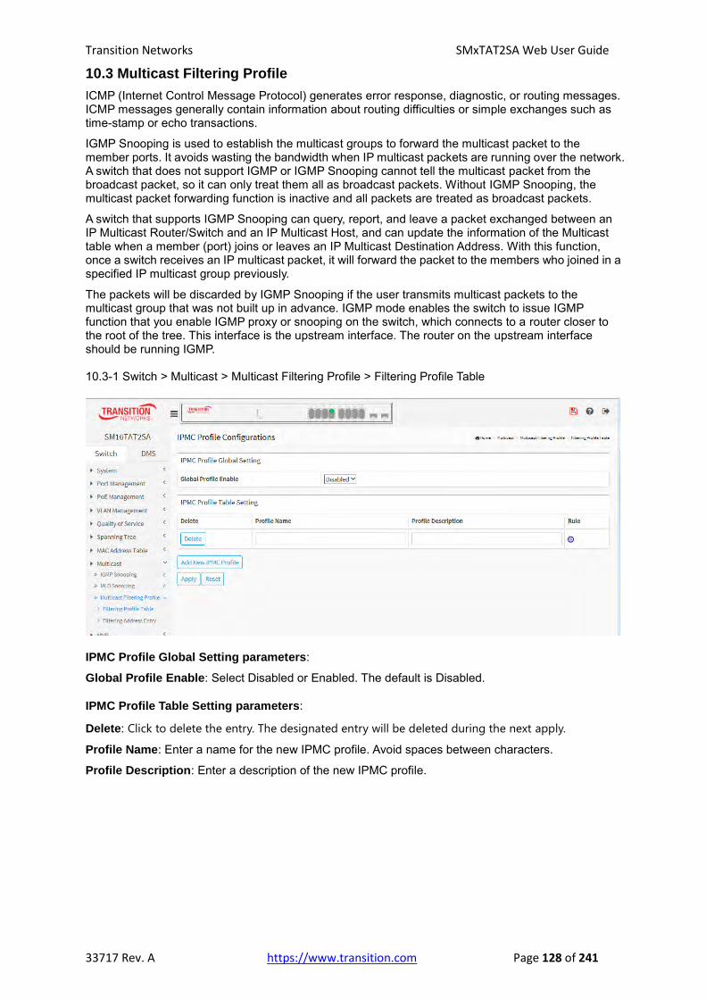
Transition Networks SMxTAT2SA Web User Guide
33717 Rev. A https://www.transition.com Page 128 of 241
10.3 Multicast Filtering Profile
ICMP (Internet Control Message Protocol) generates error response, diagnostic, or routing messages. ICMP messages generally contain information about routing difficulties or simple exchanges such as time-stamp or echo transactions.
IGMP Snooping is used to establish the multicast groups to forward the multicast packet to the member ports. It avoids wasting the bandwidth when IP multicast packets are running over the network. A switch that does not support IGMP or IGMP Snooping cannot tell the multicast packet from the broadcast packet, so it can only treat them all as broadcast packets. Without IGMP Snooping, the multicast packet forwarding function is inactive and all packets are treated as broadcast packets.
A switch that supports IGMP Snooping can query, report, and leave a packet exchanged between an IP Multicast Router/Switch and an IP Multicast Host, and can update the information of the Multicast table when a member (port) joins or leaves an IP Multicast Destination Address. With this function, once a switch receives an IP multicast packet, it will forward the packet to the members who joined in a specified IP multicast group previously.
The packets will be discarded by IGMP Snooping if the user transmits multicast packets to the multicast group that was not built up in advance. IGMP mode enables the switch to issue IGMP function that you enable IGMP proxy or snooping on the switch, which connects to a router closer to the root of the tree. This interface is the upstream interface. The router on the upstream interface should be running IGMP. 10.3-1 Switch > Multicast > Multicast Filtering Profile > Filtering Profile Table
IPMC Profile Global Setting parameters:
Global Profile Enable: Select Disabled or Enabled. The default is Disabled.
IPMC Profile Table Setting parameters:
Delete: Click to delete the entry. The designated entry will be deleted during the next apply.
Profile Name: Enter a name for the new IPMC profile. Avoid spaces between characters.
Profile Description: Enter a description of the new IPMC profile.

Transition Networks SMxTAT2SA Web User Guide
33717 Rev. A https://www.transition.com Page 129 of 241
Rule: Click the icon to display the IPMC Profile Rule Settings (In Precedence Order):
IPMC Profile Rule parameters:
Profile Name: e.g., IPMC-Profile-Cfg-Fisrt_IPMC_ProCfg.
Entry Name: Select an existing entry name at the dropdown.
Address Range: The allowed range of IP addresses.
Action: Select Deny or Permit. The default is Deny.
Log: Select Enable or Disable logging. The default is Disable.
Buttons
Add Last Rule: Click to add the last rule to the profile.
Apply: Click to save changes.
Reset: Click to undo any changes made locally and revert to previously saved values.

Transition Networks SMxTAT2SA Web User Guide
33717 Rev. A https://www.transition.com Page 130 of 241
10.3-1 Switch > Multicast > Multicast Filtering Profile > Filtering Address Entry
IPMC Profile Table Setting parameters: Delete: Click to delete the entry. The designated entry will be deleted during the next apply. Entry Name: Enter the name of the new profile. Start Address: Enter the beginning IP address of the range. End Address: Enter the ending IP address of the range. Add New Address (Range) Entry: Click the button to add a new entry line to the table for configuration.

Transition Networks SMxTAT2SA Web User Guide
33717 Rev. A https://www.transition.com Page 131 of 241
10.4 MVR
Multi VLAN Registration allows switches to automatically discover some of the VLAN information that would otherwise need to be manually configured. The MVR feature enables multicast traffic forwarding on the Multicast VLAN. In a multicast television application, a PC or a television with a set-top box can receive the multicast stream.
Multiple set-top boxes or PCs can be connected to one subscriber port, which is a switch port configured as an MVR receiver port. When a subscriber selects a channel, the set-top box or PC sends an IGMP join message to Switch A to join the appropriate multicast. Uplink ports that send and receive multicast data to and from the multicast VLAN are called MVR source ports.
10.4-1 Switch > MVR > Basic Configuration:
IPMC Profile Table Setting parameters:
Global Setting
MVR Mode: Select on or off. The default is off.
VLAN Interface Setting (Role [I:Inactive / S:Source / R:Receiver])
MVR VID: Enter the new VLAN ID for this new MVR VLAN.
MVR Name: Enter a name for this new MVR VLAN.
IGMP Address: e.g., 192.168.1.40.
Mode: At the dropdown select Dynamic or Compatible. The default is Dynamic.
Tagging: At the dropdown select Tagged or Untagged. The default is Tagged.
Priority: Enter 0 - 7.
LLQI: Enter a value from 0 - 99.
Interface Channel Profile: At the dropdown select an existing Profile name.
Port Role: For each port choose a Role; each click displays the next role (I = Inactive, S = Source role, and R = Receiver role).
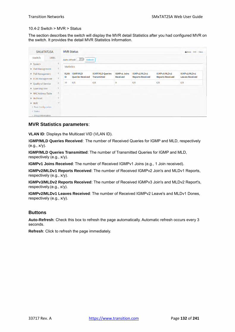
Transition Networks SMxTAT2SA Web User Guide
33717 Rev. A https://www.transition.com Page 132 of 241
10.4-2 Switch > MVR > Status
The section describes the switch will display the MVR detail Statistics after you had configured MVR on the switch. It provides the detail MVR Statistics Information.
MVR Statistics parameters:
VLAN ID: Displays the Multicast VID (VLAN ID).
IGMP/MLD Queries Received: The number of Received Queries for IGMP and MLD, respectively (e.g., x/y).
IGMP/MLD Queries Transmitted: The number of Transmitted Queries for IGMP and MLD, respectively (e.g., x/y).
IGMPv1 Joins Received: The number of Received IGMPv1 Joins (e.g., 1 Join received).
IGMPv2/MLDv1 Reports Received: The number of Received IGMPv2 Join's and MLDv1 Reports, respectively (e.g., x/y).
IGMPv3/MLDv2 Reports Received: The number of Received IGMPv3 Join's and MLDv2 Report's, respectively.(e.g., x/y).
IGMPv2/MLDv1 Leaves Received: The number of Received IGMPv2 Leave's and MLDv1 Dones, respectively (e.g., x/y).
Buttons
Auto-Refresh: Check this box to refresh the page automatically. Automatic refresh occurs every 3 seconds.
Refresh: Click to refresh the page immediately.

Transition Networks SMxTAT2SA Web User Guide
33717 Rev. A https://www.transition.com Page 133 of 241
10.4-3 Switch > MVR > Group Information
The section describes user could display the MVR Groups detail information on the switch. Entries in the MVR Group Table are shown on this page. The MVR Group Table is sorted first by VLAN ID, and then by group.
Navigating the MVR Channels (Groups) Information Table
Each page shows entries from the MVR Group table, default being 10, selected through the "entries per page" input field. When first visited, the web page will show the first 10 entries from the beginning of the MVR Channels (Groups) Information Table.
The "Search" input fields let you select the starting point in the MVR Channels (Groups) Information Table. It will update the displayed table starting from that or the closest next MVR Channels (Groups) Information Table match.
MVR Groups parameters:
VLAN ID: Displays the VID (VLAN ID) of the group.
Group: Displays the Group ID of the group displayed.
Port Members: Indicates which ports are members (the Ports under this group).
Buttons
Show entries: You can choose how many items you want to show up.
Search: You can search for the information that you want to see.
Auto-refresh: Check this box to refresh the page automatically every 3 seconds.
Refresh: Click to refresh the page immediately.
Previous: Updates the system log entries, turn to the previous page.
Next: Updates the system log entries, turn to the next page.

Transition Networks SMxTAT2SA Web User Guide
33717 Rev. A https://www.transition.com Page 134 of 241
10.4-4 Switch > MVR > SFM Information The MVR SFM (Source-Filtered Multicast) Information Table also contains the SSM (Source-Specific Multicast) information. This table is sorted first by VLAN ID, then by group, and then by Port. Different source addresses belong to the same group are treated as single entry.
Navigating the MVR SFM Information Table
Each page shows up to many entries from the MVR SFM Information table, default being 10, selected through the "entries per page" input field. When first visited, the web page will show the first 10 entries from the beginning of the MVR SFM Information Table.
The "Search" input fields lets you select the starting point in the MVR SFM Information Table. It will update the displayed table starting from that or the closest next MVR SFM Information Table match.
MVR SFM parameters: VLAN ID: Displays the VID (VLAN ID) of the group. Group: Displays the Group address of the group displayed. Port: Indicates which ports are members. Mode: Displays the filtering mode maintained per (VLAN ID, port number, Group Address) basis. It can be either Include or Exclude. Source Address: Displays the IP Address of the source. Currently, system limits the total number of IP source addresses for filtering to be 128. When there is not any source filtering address, the text "None" is shown in the Source Address field. Type: Displays the type (either Allow or Deny). Hardware Filter/Switch: Indicates whether data plane destined to the specific group address from the source IPv4/IPv6 address could be handled by chip.
Buttons
Show entries: You can choose how many items you want to show up.
Search: You can search for the information that you want to see.
Auto-refresh: Check this box to refresh the page automatically every 3 seconds.
Refresh: Click to refresh the page immediately.
Previous: Updates the system log entries, turn to the previous page.
Next: Updates the system log entries, turn to the next page.

Transition Networks SMxTAT2SA Web User Guide
33717 Rev. A https://www.transition.com Page 135 of 241
Chapter 11 DHCP
The section describes how to configure and display the DHCP Snooping
parameters of the switch.
11-1 Snooping
11-1.1 Configuration
DHCP Snooping is used to block intruder on the untrusted ports of the switch
device when it tries to intervene by injecting a bogus DHCP reply packet to a
legitimate conversation between the DHCP client and server.
The section describes how to configure the DHCP Snooping parameters of the switch.
DHCP Snooping can prevent attackers from adding their own DHCP servers to the network.
Web Interface
To configure DHCP snooping in the web interface:
1. Click DHCP, Snooping, and Configuration.
2. Select “Enabled” in the Mode of DHCP Snooping Configuration.
3. Select “Trusted” of the specific port in the Mode of Port Mode Configuration.
4. Click Apply.
Figure 11-1.1: DHCP Snooping Configuration
Parameter descriptions:
Snooping Mode : Indicates the DHCP snooping mode operation. Possible modes are:
Enabled: Enable DHCP snooping mode operation. When DHCP snooping mode operation is
enabled, the DHCP request messages will be forwarded to trusted ports and only allow reply
packets from trusted ports.
Disabled: Disable DHCP snooping mode operation.

Transition Networks SMxTAT2SA Web User Guide
33717 Rev. A https://www.transition.com Page 136 of 241
Port Mode Configuration: Indicates the DHCP snooping port mode. Possible port modes are:
Trusted: Configures the port as trusted source of the DHCP messages.
Untrusted: Configures the port as untrusted source of the DHCP messages.
Buttons
Apply : Click to save changes.
Reset : Click to undo any changes made locally and revert to previously saved values.

Transition Networks SMxTAT2SA Web User Guide
33717 Rev. A https://www.transition.com Page 137 of 241
11-1.2 Snooping Table
This page displays the dynamic IP assigned information after DHCP Snooping mode is
disabled. All DHCP clients obtained the dynamic IP address from the DHCP server will be listed
in this table except for local VLAN interface IP addresses. Entries in the Dynamic DHCP
Snooping Table are shown on this page.
Web Interface
To monitor a DHCP in the web interface:
1. Click DHCP, Snooping, and Snooping table.
Figure 11-1.2: Dynamic DHCP Snooping Table
Parameter descriptions:
Show entries: You can choose how many items you want to show.
Search: You can search for the information that you want to see.
MAC Address: User MAC address of the entry.
VLAN ID: VLAN-ID in which the DHCP traffic is permitted.
Port: Switch Port Number for which the entries are displayed.
IP Address : User IP address of the entry.
IP Subnet Mask: User IP subnet mask of the entry.
DHCP Server: DHCP Server address of the entry.
Buttons
Auto-refresh: Check this box to refresh the page automatically every 3 seconds.
Refresh: Click to refresh the page immediately.
Next: Updates the system log entries, turn to the next page.
Previous: Updates the system log entries, turn to the previous page.

Transition Networks SMxTAT2SA Web User Guide
33717 Rev. A https://www.transition.com Page 138 of 241
11-1.2 DHCP Detailed Statistics
This page provides statistics for DHCP snooping. Notice that the normal forward per-port TX statistics
isn't increased if the incoming DHCP packet is done by L3 forwarding mechanism. Also, a clear of the
statistics on specific port may not take effect on global statistics since it gathers the different layer
overview.
Web Interface
To view detailed DHCP statistics via the web interface:
1. Click DHCP, Snooping, and Detailed Statistics.
Figure 11-1.2: Dynamic DHCP Snooping Table
Parameter descriptions:
Rx and Tx Discover: The number of discover (option 53 with value 1) packets received and transmitted.
Rx and Tx Offer: The number of offer (option 53 with value 2) packets received and transmitted.
Rx and Tx Request: The number of request (option 53 with value 3) packets received and transmitted.
Rx and Tx Decline: The number of decline (option 53 with value 4) packets received and transmitted.
Rx and Tx ACK: The number of ACK (option 53 with value 5) packets received and transmitted.
Rx and Tx NAK: The number of NAK (option 53 with value 6) packets received and transmitted.
Rx and Tx Release: The number of release (option 53 with value 7) packets received and transmitted.
Rx and Tx Inform: The number of inform (option 53 with value 8) packets received and transmitted.
Rx and Tx Lease Query: The number of lease query (option 53 with value 10) packets received and
transmitted.
Rx and Tx Lease Unassigned: The number of lease unassigned (option 53 with value 11) packets
received and transmitted.
Rx and Tx Lease Unknow: The number of lease unknown (option 53 with value 12) packets received
and transmitted.
Rx and Tx Lease Active: The number of lease active (option 53 with value 13) packets received and

Transition Networks SMxTAT2SA Web User Guide
33717 Rev. A https://www.transition.com Page 139 of 241
transmitted.
Rx Discarded checksum error: The number of discard packet that IP/UDP checksum is error.
Rx Discarded from Untrusted: The number of discarded packet that are coming from untrusted port.
Buttons
: Use the Port select box to select the port that you want to display the DHCP Detailed
Statistics.
Auto-refresh: Check this box to refresh the page automatically every 3 seconds.
Refresh: Click to refresh the page immediately.
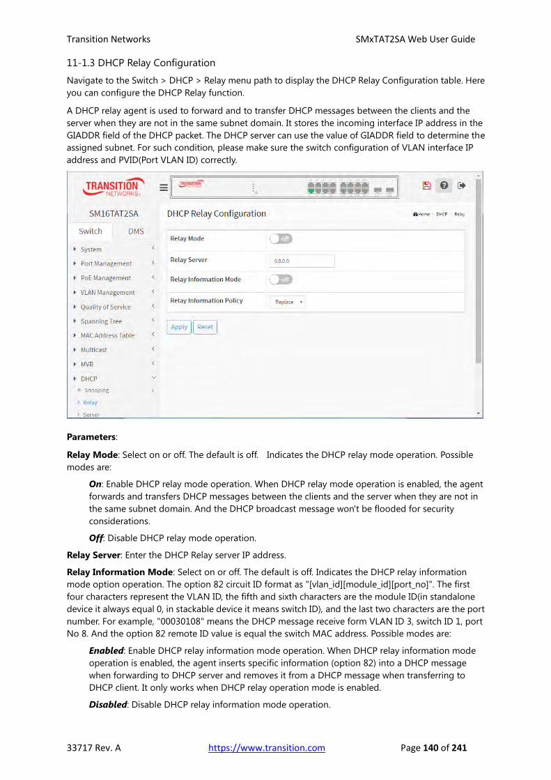
Transition Networks SMxTAT2SA Web User Guide
33717 Rev. A https://www.transition.com Page 140 of 241
11-1.3 DHCP Relay Configuration
Navigate to the Switch > DHCP > Relay menu path to display the DHCP Relay Configuration table. Here
you can configure the DHCP Relay function.
A DHCP relay agent is used to forward and to transfer DHCP messages between the clients and the
server when they are not in the same subnet domain. It stores the incoming interface IP address in the
GIADDR field of the DHCP packet. The DHCP server can use the value of GIADDR field to determine the
assigned subnet. For such condition, please make sure the switch configuration of VLAN interface IP
address and PVID(Port VLAN ID) correctly.
Parameters:
Relay Mode: Select on or off. The default is off. Indicates the DHCP relay mode operation. Possible
modes are:
On: Enable DHCP relay mode operation. When DHCP relay mode operation is enabled, the agent
forwards and transfers DHCP messages between the clients and the server when they are not in
the same subnet domain. And the DHCP broadcast message won't be flooded for security
considerations.
Off: Disable DHCP relay mode operation.
Relay Server: Enter the DHCP Relay server IP address.
Relay Information Mode: Select on or off. The default is off. Indicates the DHCP relay information
mode option operation. The option 82 circuit ID format as "[vlan_id][module_id][port_no]". The first
four characters represent the VLAN ID, the fifth and sixth characters are the module ID(in standalone
device it always equal 0, in stackable device it means switch ID), and the last two characters are the port
number. For example, "00030108" means the DHCP message receive form VLAN ID 3, switch ID 1, port
No 8. And the option 82 remote ID value is equal the switch MAC address. Possible modes are:
Enabled: Enable DHCP relay information mode operation. When DHCP relay information mode
operation is enabled, the agent inserts specific information (option 82) into a DHCP message
when forwarding to DHCP server and removes it from a DHCP message when transferring to
DHCP client. It only works when DHCP relay operation mode is enabled.
Disabled: Disable DHCP relay information mode operation.

Transition Networks SMxTAT2SA Web User Guide
33717 Rev. A https://www.transition.com Page 141 of 241
Relay Information Policy: At the dropdown, select Replace, Keep, or Drop. Indicates the DHCP relay
information mode option operation. The option 82 circuit ID format as "[vlan_id][module_id][port_no]".
The first four characters represent the VLAN ID, the fifth and sixth characters are the module ID(in
standalone device it always equal 0, in stackable device it means switch ID), and the last two characters
are the port number. For example, "00030108" means the DHCP message receive form VLAN ID 3,
switch ID 1, port No 8. And the option 82 remote ID value is equal the switch MAC address.
Possible modes are:
Enabled: Enable DHCP relay information mode operation. When DHCP relay information mode
operation is enabled, the agent inserts specific information (option 82) into a DHCP message
when forwarding to DHCP server and removes it from a DHCP message when transferring to
DHCP client. It only works when DHCP relay operation mode is enabled.
Disabled: Disable DHCP relay information mode operation.
Buttons
Apply: Click to save changes.
Reset: Click to undo any changes made locally and revert to previously saved values.

Transition Networks SMxTAT2SA Web User Guide
33717 Rev. A https://www.transition.com Page 142 of 241
11-1.3 DHCP Relay Configuration
Navigate to the Switch > DHCP > Relay menu path to display the DHCP Relay Statistics table. This page
provides statistics for DHCP relay.
Server Statistics Parameters:
Transmit to Server: The number of packets that are relayed from client to server.
Transmit Error: The number of packets that resulted in error while being relayed from client to server.
Receive from Server: The number of packets received from server.
Receive Missing Agent Option: The number of packets received without agent information options.
Receive Missing Circuit ID: The number of packets received with the Circuit ID option missing.
Receive Missing Remote ID: The number of packets received with the Remote ID option missing.
Client Statistics Parameters:
Transmit to Client: The number of relayed packets from server to client.
Transmit Error: The number of packets that resulted in error while being sent to servers.
Receive from Client: The number of received packets from server.
Receive Agent Option: The number of received packets with relay agent information option.
Replace Agent Option: The number of packets which were replaced with relay agent information
option.
Keep Agent Option: The number of packets whose relay agent information was retained.
Drop Agent Option: The number of packets that were dropped which were received with relay agent
information.
Buttons
Auto-refresh: Check this box to refresh the page automatically every 3 seconds.
Refresh: Click to refresh the page immediately.
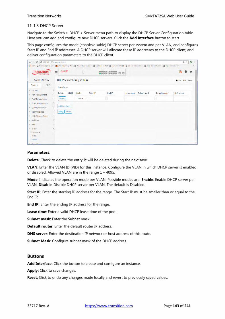
Transition Networks SMxTAT2SA Web User Guide
33717 Rev. A https://www.transition.com Page 143 of 241
11-1.3 DHCP Server
Navigate to the Switch > DHCP > Server menu path to display the DHCP Server Configuration table.
Here you can add and configure new DHCP servers. Click the Add Interface button to start.
This page configures the mode (enable/disable) DHCP server per system and per VLAN, and configures
Start IP and End IP addresses. A DHCP server will allocate these IP addresses to the DHCP client, and
deliver configuration parameters to the DHCP client.
Parameters:
Delete: Check to delete the entry. It will be deleted during the next save.
VLAN: Enter the VLAN ID (VID) for this instance. Configure the VLAN in which DHCP server is enabled
or disabled. Allowed VLAN are in the range 1 – 4095.
Mode: Indicates the operation mode per VLAN. Possible modes are: Enable: Enable DHCP server per
VLAN. Disable: Disable DHCP server per VLAN. The default is Disabled.
Start IP: Enter the starting IP address for the range. The Start IP must be smaller than or equal to the
End IP.
End IP: Enter the ending IP address for the range.
Lease time: Enter a valid DHCP lease time of the pool.
Subnet mask: Enter the Subnet mask.
Default router: Enter the default router IP address.
DNS server: Enter the destination IP network or host address of this route.
Subnet Mask: Configure subnet mask of the DHCP address.
Buttons
Add Interface: Click the button to create and configure an instance.
Apply: Click to save changes.
Reset: Click to undo any changes made locally and revert to previously saved values.

Transition Networks SMxTAT2SA Web User Guide
33717 Rev. A https://www.transition.com Page 144 of 241
Chapter 12 Security
This section explains how to configure the switch Security settings. You can use the
Security features to restrict input to an interface by limiting and identifying MAC
addresses.
12-1 Management
12-1.1 Account
This page provides an overview of the current users. Currently the only way to login
as another user on the web server is to close and reopen the browser.
Web Interface
To configure a new User via the web interface:
1. Click Security, Management, and Account.
2. Click the Add New User button.
3. Specify the User Name parameter.
4. Click Apply.
Figure 12-1.1: Account Configuration
Parameter descriptions:
User Name: The name identifying the user. This is also a link to Add/Edit User.
Password: Type the password. The allowed string length is 0 to 255, and the allowed content is the
ASCII characters from 32 to 126.
Password (again): Type the password again. You must type the same password again in the field.
Privilege Level: The privilege level of the user. The allowed range is 1 to 15. If the privilege level value
is 15, it can access all groups, i.e. that is granted the fully control of the device. But others value need to
refer to each group privilege level. User's privilege should be same or greater than the group privilege
level to have the access of that group. By default, most groups are at privilege level 5 and have
read-only access and privilege level 10 has the read-write access. The system maintenance (software
upload, factory defaults and etc.) need user privilege level 15. Generally, the privilege level 15 can be

Transition Networks SMxTAT2SA Web User Guide
33717 Rev. A https://www.transition.com Page 145 of 241
used for an administrator account, privilege level 10 for a standard user account and privilege level 5
for a guest account.
Buttons
Apply: Click to save changes.
Reset: Click to undo any changes made locally and revert to previously saved values.
Cancel: Click to undo any changes made locally and return to the Users.
Delete User: Delete the current user. This button is not available for new configurations (Add New
User).

Transition Networks SMxTAT2SA Web User Guide
33717 Rev. A https://www.transition.com Page 146 of 241
12-1.2 Privilege Level
The Security > Management > Privilege Level menu path displays the Privilege Level Configuration
table. Here you can assign Read-Only or Read-Write privilege levels for each of the major functions.
This page provides an overview of the privilege levels. The switch provides user set Group Name
Privilege Levels from 1 to 15.
Parameter descriptions:
Group Name: The name identifying the privilege group. In most cases, a privilege level group consists
of a single module (e.g. LACP, STP or QoS), but a few of them contains more than one. The following
description defines these privilege level groups in details: System: Contact, Name, Location, Timezone,
Daylight Saving Time, Log.
Privilege Levels: Every group has an authorization Privilege level for the following sub groups:
configuration read-only, configuration/execute read-write. User Privilege should be same or greater
than the authorization Privilege level to have the access to that group.
Read-Only: At the dropdown select a privilege level of 0-15 for any function (access-mgmt, account,
arp-inspection, etc.) that you want to change from the default value.
Read-Write: At the dropdown select a privilege level of 0-15 for any function (access-mgmt, account,
arp-inspection, etc.) that you want to change from the default value.
Buttons
Apply: Click to save changes.
Reset: Click to undo any changes made locally and revert to previously saved values.

Transition Networks SMxTAT2SA Web User Guide
33717 Rev. A https://www.transition.com Page 147 of 241
12-1.3 Auth Method
The Security > Management > Auth Method menu path displays the Auth Method Configuration
tables, where you can configure an authentication method (none, local, or radius) for each client (telnet,
ssh, http, https). You can also configure a service port number for telnet, ssh, http, and https clients,
and enable the HTTPS Redirect function on this page. The page also provides the Command
Authorization Method Configuration table and the Accounting Method Configuration table.
Section descriptions:
Authentication Method Configuration: The authentication section allows you to configure how a
user is authenticated when he logs into the switch via one of the management client interfaces. The
table has one row for each client type and a number of columns.
Command Authorization Method Configuration: The command authorization section allows you to
limit the CLI commands available to a user. The table has one row for each client type and a number of
columns.
Accounting Method Configuration: The accounting section allows you to configure command and
exec (login) accounting. The table has one row for each client type and a number of columns,
Parameter descriptions:
Methods: Select an authentication method (none, local, radius, or tacacs) for each client (telnet, ssh,
http, https). In the Command Authorization Method Configuration table and the Accounting Method
Configuration table, select a Method for telnet or ssh only (none or tacacs). The Method can be set to
one of the following values:
none: Authentication is disabled and login is not possible.
local: Use the local user database on the switch for authentication.
radius: Use remote RADIUS server(s) for authentication. Remote Authentication Dial In User Service
is a networking protocol that provides centralized access, authorization and accounting management
for people or computers to connect and use a network service.

Transition Networks SMxTAT2SA Web User Guide
33717 Rev. A https://www.transition.com Page 148 of 241
tacacs: Use remote TACACS+ server(s) for authentication. Terminal Access Controller Access Control
System Plus. It is a networking protocol which provides access control for routers, network access
servers and other networked computing devices via one or more centralized servers. TACACS+
provides separate authentication, authorization and accounting services.
Methods that involve remote servers are timed out if the remote servers are offline. In this case, the
next method is tried. Each method is tried from left to right and continues until a method either
approves or rejects a user. If a remote server is used for ‘primary’ authentication, it is recommended to
configure secondary authentication as 'local'. This lets the management client login via the local user
database if none of the configured authentication servers are alive.
Service Port: Enter a service port number for telnet, ssh, http, and https clients as required.
HTTPS Redirect: Check the box to force the web UI to go through https (secure HTTPS).
Cmd Lvl: Authorize all commands with a privilege level higher than or equal to this level. Valid values
are 0 - 15.
Cfg Cmd: Check to also authorize configuration commands.
Fallback: Check the box to Enable the fallback mechanism.
Exec: Check the box to Enable exec (login) accounting.
Buttons
Apply: Click to save changes.
Reset: Click to undo any changes made locally and revert to previously saved values.

Transition Networks SMxTAT2SA Web User Guide
33717 Rev. A https://www.transition.com Page 149 of 241
12-1.4 Access Management
This section shows you how to configure access management table of the Switch including
HTTP/HTTPS, SNMP, and TELNET/SSH. You can manage the Switch over an Ethernet LAN or
over the Internet.
Web Interface
To configure an Access Management Configuration in the web interface:
1. Click Security, Management, Access Management.
2. Select “on” in the Mode of Access Management Configuration.
3. Click “Add New Entry”.
4. Checked Access Management method (HTTP/HTTPS, SNMP, and TELNET/SSH) in the
entry.
5. Click Apply.
Figure 12-1.2: Access Management Configuration
Parameter descriptions:
Mode: Indicates the access management mode operation. Possible modes are:
On: Enable access management mode operation.
Off: Disable access management mode operation.
VLAN ID: Indicates the VLAN ID for the access management entry.
Delete: Check to delete the entry. It will be deleted during the next save.
IP address: Enter the source IP address.
Mask Length: Enter the Mask Length (1-30).
HTTP/HTTPS: Indicates that the host can access the switch from HTTP/HTTPS interface if the host IP
address matches the IP address range provided in the entry.
SNMP: Indicates that the host can access the switch from SNMP interface if the host IP address
matches the IP address range provided in the entry.

Transition Networks SMxTAT2SA Web User Guide
33717 Rev. A https://www.transition.com Page 150 of 241
TELNET/SSH: Indicates that the host can access the switch from TELNET/SSH interface if the host IP
address matches the IP address range provided in the entry.
Buttons
Add New Entry: Click to add a new access management entry.
Apply: Click to save changes.
Reset: Click to undo any changes made locally and revert to previously saved values.

Transition Networks SMxTAT2SA Web User Guide
33717 Rev. A https://www.transition.com Page 151 of 241
12-2 IEEE 802.1X
12-2.1 Configuration
The section describes how to configure the 802.1X parameters of the switch. You can use
802.1X to connect users to a variety of resources including Internet access, conference calls,
printing documents on shared printers, or by simply logging on to the Internet.
Web Interface
To configure the IEEE 802.1X in the web interface:
1. Click Security, IEEE 802.1X, Configuration.
2. Select “on” in the Mode of IEEE 802.1X Configuration.
3. Checked Reauthentication Enabled.
4. Set Reauthentication Period (default is 3600 seconds).
5. Select Admin State and displays Port State.
6. Click the Apply button to save the setting.
7. To cancel the setting click the Reset button to revert to previously saved values.
Figure 12-2.1: 802.1X Configuration
Parameter descriptions:
System Configuration
Mode: Select on or off. Indicates if IEEE 802.1X is globally enabled or disabled on the switch. If globally
disabled, all ports are allowed forwarding of frames.
Reauthentication Enabled: If checked, successfully authenticated supplicants/clients are
reauthenticated after the interval specified by the Reauthentication Period. Reauthentication for
802.1X-enabled ports can be used to detect if a new device is plugged into a switch port or if a

Transition Networks SMxTAT2SA Web User Guide
33717 Rev. A https://www.transition.com Page 152 of 241
supplicant is no longer attached.
For MAC-based ports, reauthentication is only useful if the RADIUS server configuration has changed.
It does not involve communication between the switch and the client, and therefore doesn't imply that
a client is still present on a port (see Aging Period below).
Reauthentication Period: Determines the period, in seconds, after which a connected client must be
reauthenticated. This is only active if the Reauthentication Enabled checkbox is checked. Valid values
are in the range 1 to 3600 seconds.
EAPOL Timeout: Determines the time for retransmission of Request Identity EAPOL frames. Valid
values are in the range 1 to 255 seconds. This has no effect for MAC-based ports.
Guest VLAN Enabled: A Guest VLAN is a special VLAN - typically with limited network access - on
which 802.1X-unaware clients are placed after a network administrator-defined timeout. The switch
follows a set of rules for entering and leaving the Guest VLAN as listed below.
The "Guest VLAN Enabled" checkbox provides a quick way to globally enable/disable Guest VLAN
functionality. When checked, the individual ports' ditto setting determines whether the port can be
moved into Guest VLAN. When unchecked, the ability to move to the Guest VLAN is disabled on all
ports.
Guest VLAN ID: This is the value that a port's Port VLAN ID is set to if a port is moved into the Guest
VLAN. It is only changeable if the Guest VLAN option is globally enabled. Valid values are 1- 4094.
Max. Reauth. Count: The number of times the switch transmits an EAPOL Request Identity frame
without response before considering entering the Guest VLAN is adjusted with this setting. The value
can only be changed if the Guest VLAN option is globally enabled. Valid values are in the range [1;
255].
Allow Guest VLAN if EAPOL Seen: The switch remembers if an EAPOL frame has been received on the
port for the life-time of the port. Once the switch considers whether to enter the Guest VLAN, it will
first check if this option is enabled or disabled. If disabled (unchecked; default), the switch will only
enter the Guest VLAN if an EAPOL frame has not been received on the port for the life-time of the port.
If enabled (checked), the switch will consider entering the Guest VLAN even if an EAPOL frame has
been received on the port for the life-time of the port. The value can only be changed if the Guest
VLAN option is globally enabled.
Port Configuration
Port: The port number for which the configuration below applies.
Admin State: If 802.1X is globally enabled, this selection controls the port's authentication mode.
These modes are available:
Force Authorized: In this mode, the switch will send one EAPOL Success frame when the port
link comes up, and any client on the port will be allowed network access without
authentication.
Force Unauthorized: In this mode, the switch will send one EAPOL Failure frame when the
port link comes up, and any client on the port will be disallowed network access.
Port-based 802.1X: In the 802.1X-world, the user is called the supplicant, the switch is the
authenticator, and the RADIUS server is the authentication server. The authenticator acts as
the man-in-the-middle, forwarding requests and responses between the supplicant and the
authentication server. Frames sent between the supplicant and the switch are special 802.1X
frames, known as EAPOL (EAP Over LANs) frames. EAPOL frames encapsulate EAP PDUs
(RFC3748). Frames sent between the switch and the RADIUS server are RADIUS packets.
RADIUS packets also encapsulate EAP PDUs together with other attributes like the switch's IP
address, name, and the supplicant's port number on the switch. EAP is very flexible, in that it
allows for different authentication methods, like MD5-Challenge, PEAP, and TLS. The
important thing is that the authenticator (the switch) doesn't need to know which
authentication method the supplicant and the authentication server are using, or how many

Transition Networks SMxTAT2SA Web User Guide
33717 Rev. A https://www.transition.com Page 153 of 241
information exchange frames are needed for a particular method. The switch simply
encapsulates the EAP part of the frame into the relevant type (EAPOL or RADIUS) and
forwards it.
When authentication is complete, the RADIUS server sends a special packet containing a
success or failure indication. Besides forwarding this decision to the supplicant, the switch
uses it to open up or block traffic on the switch port connected to the supplicant
NOTE: Suppose two backend servers are enabled and that the server timeout is
configured to X seconds (using the AAA configuration page), and suppose that the first
server in the list is currently down (but not considered dead).
Now, if the supplicant retransmits EAPOL Start frames at a rate faster than X seconds, then
it will never get authenticated, because the switch will cancel on-going backend
authentication server requests whenever it receives a new EAPOL Start frame from the
supplicant.
And since the server hasn't yet failed (because the X seconds haven't expired), the same
server will be contacted upon the next backend authentication server request from the
switch. This scenario will loop forever. Therefore, the server timeout should be smaller
than the supplicant's EAPOL Start frame retransmission rate.
Guest VLAN Enabled
When Guest VLAN is both globally enabled and enabled (checked) for a given port, the switch
considers moving the port into the Guest VLAN according to the rules outlined below.
This option is only available for EAPOL-based modes, i.e.:
Port-based 802.1X
Single 802.1X
Multi 802.1X
For troubleshooting VLAN assignments, use the "Monitor>VLANs>VLAN Membership and VLAN Port"
pages. These pages show which modules have (temporarily) overridden the current Port VLAN
configuration.
Guest VLAN Operation:
When a Guest VLAN enabled port's link comes up, the switch starts transmitting EAPOL Request
Identity frames. If the number of transmissions of such frames exceeds Max. Reauth. Count and no
EAPOL frames have been received in the meanwhile, the switch considers entering the Guest VLAN.
The interval between transmission of EAPOL Request Identity frames is configured with EAPOL Timeout.
If Allow Guest VLAN if EAPOL Seen is enabled, the port will now be placed in the Guest VLAN. If
disabled, the switch will first check its history to see if an EAPOL frame has previously been received on
the port (this history is cleared if the port link goes down or the port's Admin State is changed), and if
not, the port will be placed in the Guest VLAN. Otherwise it will not move to the Guest VLAN, but
continue transmitting EAPOL Request Identity frames at the rate given by EAPOL Timeout.
Once in the Guest VLAN, the port is considered authenticated, and all attached clients on the port are
allowed access on this VLAN. The switch will not transmit an EAPOL Success frame when entering the
Guest VLAN.
While in the Guest VLAN, the switch monitors the link for EAPOL frames, and if one such frame is
received, the switch immediately takes the port out of the Guest VLAN and starts authenticating the
supplicant according to the port mode. If an EAPOL frame is received, the port will never be able to go
back into the Guest VLAN if the "Allow Guest VLAN if EAPOL Seen" is disabled.
Port State : The current state of the port. It can undertake one of the following values:
Globally Disabled: IEEE 802.1X is globally disabled.
Link Down: IEEE 802.1X is globally enabled, but there is no link on the port.
Authorized: The port is in Force Authorized or a single-supplicant mode and the supplicant

Transition Networks SMxTAT2SA Web User Guide
33717 Rev. A https://www.transition.com Page 154 of 241
is authorized.
Unauthorized: The port is in Force Unauthorized or a single-supplicant mode and the
supplicant is not successfully authorized by the RADIUS server.
X Auth/Y Unauth: The port is in a multi-supplicant mode. Currently X clients are authorized
and Y are unauthorized.
Restart: Two buttons are available for each row. The buttons are only enabled when authentication is
globally enabled and the port's Admin State is in an EAPOL-based or MAC-based mode.
Clicking these buttons will not cause settings changed on the page to take effect.
Re-authenticate: Schedules a re-authentication whenever the quiet-period of the port runs out
(EAPOL-based authentication). For MAC-based authentication, re-authentication will be attempted
immediately. The button only has effect for successfully authenticated clients on the port and will not
cause the clients to get temporarily unauthorized.
Reinitialize: Forces a re-initialization of the clients on the port and thereby a re-authentication
immediately. The clients will transfer to the unauthorized state while the re-authentication is in
progress.
Buttons
Apply : Click to save changes.
Reset : Click to undo any changes made locally and revert to previously saved values.
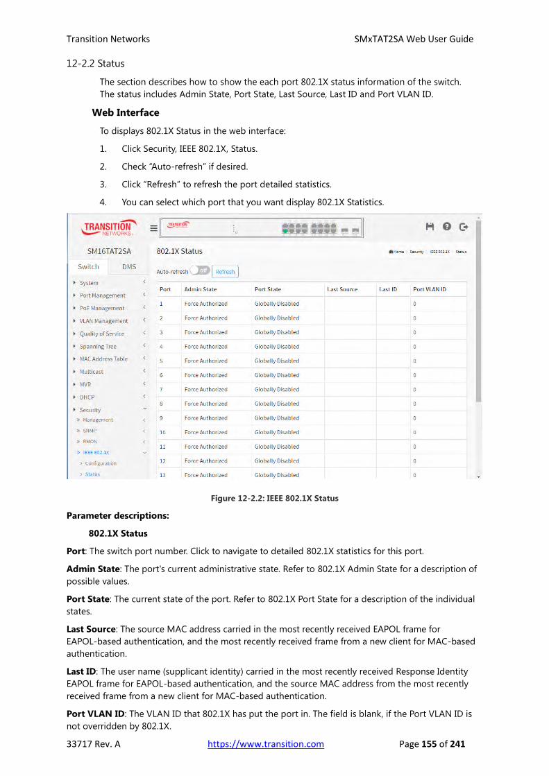
Transition Networks SMxTAT2SA Web User Guide
33717 Rev. A https://www.transition.com Page 155 of 241
12-2.2 Status
The section describes how to show the each port 802.1X status information of the switch.
The status includes Admin State, Port State, Last Source, Last ID and Port VLAN ID.
Web Interface
To displays 802.1X Status in the web interface:
1. Click Security, IEEE 802.1X, Status.
2. Check “Auto-refresh” if desired.
3. Click “Refresh” to refresh the port detailed statistics.
4. You can select which port that you want display 802.1X Statistics.
Figure 12-2.2: IEEE 802.1X Status
Parameter descriptions:
802.1X Status
Port: The switch port number. Click to navigate to detailed 802.1X statistics for this port.
Admin State: The port's current administrative state. Refer to 802.1X Admin State for a description of
possible values.
Port State: The current state of the port. Refer to 802.1X Port State for a description of the individual
states.
Last Source: The source MAC address carried in the most recently received EAPOL frame for
EAPOL-based authentication, and the most recently received frame from a new client for MAC-based
authentication.
Last ID: The user name (supplicant identity) carried in the most recently received Response Identity
EAPOL frame for EAPOL-based authentication, and the source MAC address from the most recently
received frame from a new client for MAC-based authentication.
Port VLAN ID: The VLAN ID that 802.1X has put the port in. The field is blank, if the Port VLAN ID is
not overridden by 802.1X.

Transition Networks SMxTAT2SA Web User Guide
33717 Rev. A https://www.transition.com Page 156 of 241
If the VLAN ID is assigned by the RADIUS server, "(RADIUS-assigned)" is appended to the VLAN ID.
Read more about RADIUS-assigned VLANs here.
If the port is moved to the Guest VLAN, "(Guest)" is appended to the VLAN ID. Read more about Guest
VLANs here.
Buttons
Auto-refresh: Check this box to refresh the page automatically every 3 seconds.
Refresh: Click to refresh the page immediately.
If you select port1 to display 802.1X Statistics:
Figure 12-2.2: 802.1X Statistics Port 1
Parameter descriptions:
Port: You can select which port that you want display 802.1X Statistics.
Admin State: The port's current administrative state. Refer to 802.1X Admin State for a description of
possible values.
Port State: The current state of the port. Refer to 802.1X Port State for a description of the individual
states.
Buttons
Auto-refresh: Check this box to refresh the page automatically every 3 seconds.
Refresh: Click to refresh the page.
Clear: Clears the counters for the selected port.

Transition Networks SMxTAT2SA Web User Guide
33717 Rev. A https://www.transition.com Page 157 of 241
12-3 Port Security
12-3.1 Configuration
This section shows you how to configure the Port Security settings of the Switch. You can use
the Port Security feature to restrict input to an interface by limiting and identifying MAC
addresses.
Web Interface
To configure a Port Security Configuration in the web interface:
1. Click Security, Port Security, Configuration.
2. Select “Enabled” in the Mode of System Configuration.
3. Set Mode (Enabled or Disabled), Limit, Action (Trap, Shutdown, Trap & Shutdown) for
each port.
4. Click the Apply button to save the settings.
5. To cancel the settings click the Reset button to restore previously saved values.
Figure 12-3.1: Port Security Configuration
Parameter descriptions:
System Configuration
Mode: Indicates if Limit Control is globally enabled or disabled on the switch. If globally disabled, other
modules may still use the underlying functionality, but limit checks and corresponding actions are
disabled.
Port Configuration table has one row for each switch port and a number of columns:
Port: The port number to which the configuration below applies.
Mode: Controls whether Limit Control is enabled on this port. Both this and the Global Mode must be
set to Enabled for Limit Control to be in effect. Notice that other modules may still use the underlying
port security features without enabling Limit Control on a given port.

Transition Networks SMxTAT2SA Web User Guide
33717 Rev. A https://www.transition.com Page 158 of 241
Limit: The maximum number of MAC addresses that can be secured on this port. This number cannot
exceed 1024. If the limit is exceeded, the corresponding action is taken.
The switch is "born" with a total number of MAC addresses from which all ports draw whenever a new
MAC address is seen on a Port Security-enabled port. Since all ports draw from the same pool, it may
happen that a configured maximum cannot be granted, if the remaining ports have already used all
available MAC addresses.
Action: If Limit is reached, the switch can take one of the following actions:
None: Do not allow more than Limit MAC addresses on the port, but take no further action.
Trap: If Limit + 1 MAC addresses seen on the port, send an SNMP trap. If Aging is disabled, only
one SNMP trap will be sent, but with Aging enabled, new SNMP traps will be sent every time the
limit gets exceeded.
Shutdown: If Limit + 1 MAC addresses is seen on the port, shut down the port. This implies that
all secured MAC addresses will be removed from the port, and no new address will be learned.
Even if the link is physically disconnected and reconnected on the port (by disconnecting the
cable), the port will remain shut down. There are three ways to re-open the port:
1) Boot the switch,
2) Disable and re-enable Limit Control on the port or the switch,
3) Click the Reopen button.
Trap & Shutdown: If Limit + 1 MAC addresses is seen on the port, both the "Trap" and the
"Shutdown" actions described above will be taken.
State: This column shows the current state of the port as seen from the Limit Control's point of view.
The state takes one of four values:
Disabled: Limit Control is either globally disabled or disabled on the port.
Ready: The limit is not yet reached. This can be shown for all actions.
Limit Reached: Indicates that the limit is reached on this port. This state can only be shown if
Action is set to none or Trap.
Shutdown: Indicates that the port is shut down by the Limit Control module. This state can only
be shown if Action is set to Shut Down or Trap & Shutdown.
Re-open Button: If a port is shut down by this module, you may reopen it by clicking this button,
which will only be enabled if this is the case. For other methods, refer to shut down in the Action
section.
NOTE: Clicking the Re-open button causes the page to be refreshed, so
non-committed changes will be lost.
Buttons
Apply: Click to save changes.
Reset: Click to undo any changes made locally and revert to previously saved values.

Transition Networks SMxTAT2SA Web User Guide
33717 Rev. A https://www.transition.com Page 159 of 241
12-3.2 Status
This section shows the Port Security status. Port Security is a module with no direct
configuration. Configuration comes indirectly from other modules - the user modules. When a
user module has enabled port security on a port, the port is set-up for software-based
learning. In this mode, frames from unknown MAC addresses are passed on to the port
security module, which in turn asks all user modules whether to allow this new MAC address to
forward or block it. For a MAC address to be set in the forwarding state, all enabled user
modules must unanimously agree on allowing the MAC address to forward. If only one
chooses to block it, it will be blocked until that user module decides otherwise. The status page
is divided into two sections - one with a legend of user modules and one with the actual port
status.
Web Interface
To displays a Port Security Status in the web interface:
1. Click Security, Port Security, and Status.
2. Check “Auto-refresh” if desired.
3. Click “Refresh” to refresh the port detailed statistics.
4. Click the port number to see the status for this particular port.
Figure 12-3.2: Port Security Status
Parameter descriptions:
Port: The port number for which the status applies. Click the port number to see the status for this
particular port.
State: Shows the current state of the port. It can take one of four values:
Disabled: No user modules are currently using the Port Security service.
Ready: The Port Security service is in use by at least one user module, and is awaiting frames from
unknown MAC addresses to arrive.
Limit Reach: The Port Security service is enabled by at least the Limit Control user module, and
that module has indicated that the limit is reached and no more MAC addresses should be taken
in.
Shutdown: The Port Security service is enabled by at least the Limit Control user module, and that
module has indicated that the limit is exceeded. No MAC addresses can be learned on the port
until it is administratively re-opened on the Limit Control configuration Web-page.
MAC Count (Current, Limit): The two columns indicate the number of currently learned MAC
addresses (forwarding as well as blocked) and the maximum number of MAC addresses that can be
learned on the port, respectively. If no user modules are enabled on the port, the Current column will
show a dash (-).

Transition Networks SMxTAT2SA Web User Guide
33717 Rev. A https://www.transition.com Page 160 of 241
Buttons
Auto-refresh: Check this box to refresh the page automatically every 3
seconds.
Refresh: Click to refresh the page immediately.

Transition Networks SMxTAT2SA Web User Guide
33717 Rev. A https://www.transition.com Page 161 of 241
12-3 IP Source Guard
The IP Source Guard security feature restricts IP traffic on untrusted Layer 2 ports by filtering traffic
based on the DHCP snooping binding database or manually configured IP source bindings. This feature
helps prevent IP spoofing attacks.
12-3.1 Configuration
Navigate to Security > IP Source Guard > Configuration to configure IP Source Guard mode and port
mode settings and the max dynamic clients.
IP Source Guard Configuration parameters:
Mode: Select the global mode (on or off). The default is off.
Port: A row for configuring each port.
Mode: Select the mode for each port (Enabled or Disabled). The default is Disabled.
Max Dynamic Clients: At the dropdown select 0, 1, 2 or Unlimited. The default is Unlimited.

Transition Networks SMxTAT2SA Web User Guide
33717 Rev. A https://www.transition.com Page 162 of 241
12-3.2 Static Table
Navigate to Security > IP Source Guard > Static Table to create new Static IP Source Guard entries.
Static IP Source Guard Table parameters:
Add New Entry: Click the button to add a row for configuring.
Port: At the dropdown select the port to be configured.
IP Address: Enter the IP address for this new entry.
MAC Address: Enter the MAC address for this new entry (must be a valid unicast MAC address).
Apply: Click the Apply button when done.
12-3.3 Dynamic Table
The Security > IP Source Guard > Dynamic Table displays data on existing entries.
Dynamic IP Source Guard Table parameters:
Port: Displays the configured port.
IP Address: Displays the IP address for the entry.
MAC Address: Displays the MAC address for the entry.
Previous: Click the button to display the previous set of entries.
Next: Click the button to display the next set of entries.

Transition Networks SMxTAT2SA Web User Guide
33717 Rev. A https://www.transition.com Page 163 of 241
12-4 ARP Inspection
12-4.1 Port Configuration
The Security > ARP Inspection > Port Configuration page displays the Port Mode Configuration table.
Parameters:
Mode: The global mode setting (on or off). The default is off.
Port: A row for each port to be configured.
Mode: Check the box if configured.
Check VLAN: Check the box if configured.
Log Type: Select None, Deny, Permit, or All. The default is None.
Apply: Click the button when done configuring.

Transition Networks SMxTAT2SA Web User Guide
33717 Rev. A https://www.transition.com Page 164 of 241
12-4.2 VLAN Configuration
The Security > ARP Inspection > VLAN Configuration page displays the VLAN Mode Configuration
table.
Parameters:
Add New Entry: Click the button to add a row for configuring.
VLAN ID: The VID for this instance.
Log Type: Select None, Deny, Permit, or All. The default is None.
Apply: Click the Apply button when done configuring.
12-4.3 Static Table
Navigate to the Security > ARP Inspection > Static Table menu path to display the Static ARP Inspection
Table:
Parameters:
Add New Entry: Click the button to add a row for configuring.
Port: Select the port being configured.
VLAN ID: The VID for this instance.
MAC Address: Enter the MAC address for the entry. Must be a valid unicast MAC address.
IP Address: Enter the IP address for the entry.
Apply: Click the Apply button when done configuring.

Transition Networks SMxTAT2SA Web User Guide
33717 Rev. A https://www.transition.com Page 165 of 241
12-4.4 Dynamic Table
Navigate to the Security > ARP Inspection > Dynamic Table menu path to display the Dynamic ARP
Inspection Table.
Parameters:
Port: Select the port being configured.
VLAN ID: The VID for this instance.
MAC Address: Enter the MAC address for the entry.
IP Address: Enter the IP address for the entry.
Buttons:
Apply: Click to save changes when done configuring.
Reset: Click to undo any changes made locally and revert to previously saved values.
Previous: Click the button to display the previous set of entries.
Next: Click the button to display the next set of entries.

Transition Networks SMxTAT2SA Web User Guide
33717 Rev. A https://www.transition.com Page 166 of 241
12-5 SNMP
The Security > SNMP menu path lets you configure SNMP Communities, Groups,
Views, and Access and Trap Event Security.
12-5.1 Configuration Security > SNMP > Configuration
This section describes how to configure SNMP System on the switch. This function is
used to configure SNMP settings, community name, trap host and public traps as well
as the throttle of SNMP. A SNMP manager must pass the authentication by identifying
both community names, then it can access the MIB information of the target device.
So, both parties must have the same community name. Once completing the setting, click button, the
setting takes effect.
SNMP Configuration Parameters:
Read Community: Indicates the community read access string to permit access to SNMP agent. The
allowed string length is 1 to 31, and the allowed content is the ASCII characters from 33 to 126. The
field is applicable only when SNMP version is SNMPv1 or SNMPv2c. If SNMP version is SNMPv3, the
community string will be associated with SNMPv3 communities table. It provides more flexibility to
configure security name than a SNMPv1 or SNMPv2c community string. In addition to community
string, a particular range of source addresses can be used to restrict source subnet
Write Community: Indicates the community write access string to permit access to SNMP agent.
The allowed string length is 1 to 31, and the allowed content is the ASCII characters from 33 to 126.
The field is applicable only when SNMP version is SNMPv1 or SNMPv2c. If SNMP version is SNMPv3,
the community string will be associated with SNMPv3 communities table. It provides more flexibility to
configure security name than a SNMPv1 or SNMPv2c community string. In addition to community
string, a particular range of source addresses can be used to restrict source subnet. At the dropdown
you can select Enabled (default) or Disabled.
Buttons
Apply: Click to save changes.
Reset: Click to undo any changes made locally and revert to previously saved values.

Transition Networks SMxTAT2SA Web User Guide
33717 Rev. A https://www.transition.com Page 167 of 241
12-5.2 SNMPv3 Security > SNMP > SNMPv3 > Communities
The function is used to configure SNMPv3 communities. The Community is unique. To create a new
community account, please check <Add New Entry> button, and enter the account information then
check the Apply button. You can create up to six Groups.
Parameters:
Community: Enter the IP address for this new entry. Indicates the community access string to permit
access to SNMPv3 agent. The allowed string length is 1 to 32, and the allowed content is ASCII
characters from 33 to 126. The community string will be treated as security name and map a SNMPv1
or SNMPv2c community string.
Source IP: Enter the IP address for this new entry. Indicates the SNMP access source address. A
particular range of source addresses can be used to restrict source subnet when combined with source
mask.
Source Mask: Enter the Source Mask for this new entry. Indicates the SNMP access source address
mask.
Add New Entry: Click to add a row to the table and configure the new instance.
Apply: Click to save changes when done configuring.
Reset: Click to undo any changes made locally and revert to previously saved values.

Transition Networks SMxTAT2SA Web User Guide
33717 Rev. A https://www.transition.com Page 168 of 241
Security > SNMP > SNMPv3 >Users
The function is used to configure SNMPv3 user. The Entry index key is User Name. To create a new User
Name account, please check <Add new user> button, and enter the user information then click the
Apply button. You can create up to six Groups.
Parameters:
UserName: Enter a name for this new user entry. A string identifying the user name that this entry
should belong to. The allowed string length is 1 to 31, and the allowed content is ASCII characters from
33 to 126.
SecurityLevel: Select Auth, Priv or Auth, no Priv or no Auth, Priv for the desired combination of
Privacy and Authentication. Security Level indicates the security model that this entry should belong to.
Possible security models are:
NoAuth, NoPriv: No authentication and no privacy.
Auth, NoPriv: Authentication and no privacy.
Auth, Priv: Authentication and privacy.
The value of security level cannot be modified if entry already exists. That means it must first be
ensured that the value is set correctly.
AuthenticationProtocol: If Authentication is configured, select a protocol; either MD5 (uses the
Merkle–Damgård construction) or SHA (Secure Hash Algorithm). Note: The value of security level
cannot be modified if an entry already exists. That means you must first ensure that the value is set
correctly.
AuthenticationPassword: If Authentication is configured, enter a password for authenticating. A string
identifying the authentication password phrase. For MD5 authentication protocol, the allowed string
length is 8 to 39. For SHA authentication protocol, the allowed string length is 8 to 39. The allowed
content is ASCII characters from 33 to 126.
PrivacyProtocol: If Privacy is configured, select a protocol; either DES (Data Encryption Standard) or
AES (Advanced Encryption Standard). Indicates the privacy protocol that this entry should belong to.
Possible privacy protocols are:
DES: An optional flag to indicate that this user uses DES authentication protocol.
AES: An optional flag to indicate that this user uses AES authentication protocol.
PrivacyPassword: If Privacy is configured, enter a password for privacy. A string identifying the privacy
password phrase. The allowed string length is 8 to 31, and the allowed content is ASCII characters from
33 to 126.
Add New Entry: Click to add new entry. Specify the name and configure the new entry. Click the Apply
button.

Transition Networks SMxTAT2SA Web User Guide
33717 Rev. A https://www.transition.com Page 169 of 241
Security > SNMP > SNMPv3 > Groups
The function is used to configure SNMPv3 group. The Entry index key are Security Model and Security
Name. To create a new group account, check the Add New Group button, and enter the group
information then click the Apply button. You can create up to 12 SNMP Groups.
Parameters:
Security Model: Select v1, v2c, or usm (User-based Security Model). Indicates the security model that
this entry should belong to. Possible security models are:
v1: Reserved for SNMPv1.
v2c: Reserved for SNMPv2c.
usm: User-based Security Model (USM).
User Name: At the dropdown select an existing User Name to become a member of this new group.
A string identifying the security name that this entry should belong to. The allowed string length is 1 to
31, and the allowed content is ASCII characters from 33 to 126.
Group Name: Enter the name for the new Group. A string identifying the group name that this entry
should belong to. The allowed string length is 1 to 32, and the allowed content is ASCII characters from
33 to 126.
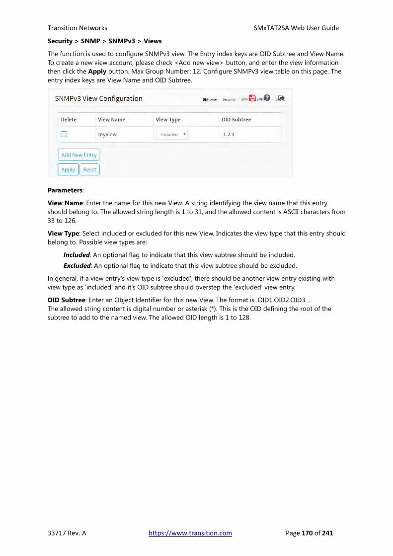
Transition Networks SMxTAT2SA Web User Guide
33717 Rev. A https://www.transition.com Page 170 of 241
Security > SNMP > SNMPv3 > Views
The function is used to configure SNMPv3 view. The Entry index keys are OID Subtree and View Name.
To create a new view account, please check <Add new view> button, and enter the view information
then click the Apply button. Max Group Number: 12. Configure SNMPv3 view table on this page. The
entry index keys are View Name and OID Subtree.
Parameters:
View Name: Enter the name for this new View. A string identifying the view name that this entry
should belong to. The allowed string length is 1 to 31, and the allowed content is ASCII characters from
33 to 126.
View Type: Select included or excluded for this new View. Indicates the view type that this entry should
belong to. Possible view types are:
Included: An optional flag to indicate that this view subtree should be included.
Excluded: An optional flag to indicate that this view subtree should be excluded.
In general, if a view entry's view type is 'excluded', there should be another view entry existing with
view type as 'included' and it's OID subtree should overstep the 'excluded' view entry.
OID Subtree: Enter an Object Identifier for this new View. The format is .OID1.OID2.OID3 ...
The allowed string content is digital number or asterisk (*). This is the OID defining the root of the
subtree to add to the named view. The allowed OID length is 1 to 128.

Transition Networks SMxTAT2SA Web User Guide
33717 Rev. A https://www.transition.com Page 171 of 241
Security > SNMP > SNMPv3 > Access
The function is used to configure SNMPv3 accesses. The Entry index key are Group Name, Security
Model and Security level. To create a new access account, click the Add New Entry button, enter the
access information, and then check the Apply button. You can create up to 12 Groups.
Parameters:
Group Name: Select the name of the existing Group. A string identifying the group name that this
entry should belong to. The allowed string length is 1 to 31, and the allowed content is ASCII characters
from 33 to 126.
Security Model: Select any, v1, v2c, or usm for this instance. Indicates the security model that this
entry should belong to. Possible security models are:
Any: Any security model accepted(v1|v2c|usm).
v1: Reserved for SNMPv1.
v2c: Reserved for SNMPv2c.
usm: User-based Security Model (USM).
Security Level: Select the level of security to be applied (NoAuth, NoPriv, or Auth, NoPriv, or
Auth, Priv. Indicates the security model that this entry should belong to. Possible security models are:
NoAuth, NoPriv: No authentication and no privacy.
Auth, NoPriv: Authentication and no privacy.
Auth, Priv: Authentication and privacy.
Read View Name: Select None or an existing Read View Name at the dropdown. This is the name of
the MIB view defining the MIB objects for which this request may request the current values. The
allowed string length is 1 to 31, and the allowed content is ASCII characters from 33 to 126.
Write View Name: Select None or an existing Write View Name at the dropdown. This is the name of
the MIB view defining the MIB objects for which this request may potentially set new values. The
allowed string length is 1 to 31, and the allowed content is ASCII characters from 33 to 126.
Buttons
Add New Entry: Click to add a new instance. An empty row is added to the table, and the new instance
can be configured as needed.
Apply: Click to save changes.
Reset: Click to undo any changes made locally and revert to previously saved values.

Transition Networks SMxTAT2SA Web User Guide
33717 Rev. A https://www.transition.com Page 172 of 241
Security > SNMP > Trap Event Severity
This page displays the Trap Event Severity Configuration table:
Parameters:
Group Name: Select the name of the existing Group. This is the name identifying the severity group.
Severity Level: At the dropdown select Emerg, Alert, Crit, Error, Warning, Notice, Info, or Debug.
Every group has an severity level. These 7 levels are supported:
Emergency: System is unusable.
Alert: Action must be taken immediately.
Critical: Critical conditions.
Error: Error conditions.
Warning: Warning conditions.
Notice: Normal but significant conditions.
Information: Information messages.
Debug: Debug-level messages.
Syslog: Check the box to enable System logging of the trap event.
Trap: Check the box to enable the trap event setting.

Transition Networks SMxTAT2SA Web User Guide
33717 Rev. A https://www.transition.com Page 173 of 241
12-4 RADIUS
12-4.1 Configuration
Web Interface
To configure a RADIUS in the web interface:
1. Click Security, RADIUS, Configuration.
2. Set Timeout, Retransmit, Deadtime, Key, NAS-IP-Address, NAS
IPv6-Address,NAS-Identifier.
3. Click “Add New Entry”.
4. Set Hostname, Auth Port, Acct Port, Timeout, Retransmit, Key.
5. Click the Apply button to save the setting.
6. To cancel the setting, click the Reset button to revert to previously saved values.
Figure 12-4.1: RADIUS Server Configuration
Parameter descriptions:
Global Configuration
These setting are common for all of the RADIUS servers.
Timeout: Timeout is the number of seconds, in the range 1 to 1000, to wait for a reply from a RADIUS
server before retransmitting the request.
Retransmit: Retransmit is the number of times, in the range 1 to 1000, a RADIUS request is
retransmitted to a server that is not responding. If the server has not responded after the last
retransmit it is considered to be dead.
Deadtime: Deadtime, which can be set to a number between 0 to 1440 minutes, is the period during
which the switch will not send new requests to a server that has failed to respond to a previous request.
This will stop the switch from continually trying to contact a server that it has already determined as
dead. Setting the Deadtime to a value greater than 0 (zero) will enable this feature, but only if more
than one server has been configured.
Transition Networks SMxTAT2SA Web User Guide
33717 Rev. A https://www.transition.com Page 174 of 241
Key: The secret key - up to 63 characters long - shared between the RADIUS server and the switch.
NAS-IP-Address: The IPv4 address to be used as attribute 4 in RADIUS Access-Request packets. If this
field is left blank, the IP address of the outgoing interface is used.
NAS-IPv6-Address: The IPv6 address to be used as attribute 95 in RADIUS Access-Request packets.
If this field is left blank, the IP address of the outgoing interface is used.
NAS-Identifier: The identifier - up to 255 characters long - to be used as attribute 32 in RADIUS
Access-Request packets. If this field is left blank, the NAS-Identifier is not included in the packet.
Server Configuration: The table has one row for each RADIUS server and a number of columns,
which are:
Delete: To delete a RADIUS server entry, check this box. The entry will be deleted during the next Save.
Hostname: The IP address or hostname of the RADIUS server.
Auth Port: The UDP port to use on the RADIUS server for authentication.
Acct Port: The UDP port to use on the RADIUS server for accounting.
Timeout: This optional setting overrides the global timeout value. Leaving it blank will use the global
timeout value.
Retransmit: This optional setting overrides the global retransmit value. Leaving it blank will use the
global retransmit value.
Key: This optional setting overrides the global key. Leaving it blank will use the global key.
Buttons
Add New Server Entry: Click to add a new RADIUS server. An empty row is added to the table, and the
RADIUS server can be configured as needed. Up to 5 servers are supported. The Reset button can be
used to undo the addition of the new server.
Apply: Click to save changes.
Reset: Click to undo any changes made locally and revert to previously saved values.

Transition Networks SMxTAT2SA Web User Guide
33717 Rev. A https://www.transition.com Page 175 of 241
12-4.2 Status
This section shows you an overview/detail of the RADIUS Authentication and Accounting
servers’ status to ensure the function is workable.
Web Interface
To display a RADIUS Status in the web interface:
1. Click Security, RADIUS, and Status.
2. Select a Server line to display the detail statistics for a particular RADIUS server.
Figure 12-4.2: RADIUS Server Status
Parameter descriptions:
RADIUS Authentication Server Status
# : The RADIUS server number. Click to navigate to detailed statistics for this server.
IP Address : The IP address and UDP port number (in <IP Address>:<UDP Port> notation) of this
server.
State : The current state of the server. This field takes one of the following values:
Disabled : The server is disabled.
Not Ready : The server is enabled, but IP communication is not yet up and running.
Ready : The server is enabled, IP communication is up and running, and the RADIUS module is
ready to accept access attempts.
Dead (X seconds left) : Access attempts were made to this server, but it did not reply within the
configured timeout. The server has temporarily been disabled, but will get re-enabled when the
dead-time expires. The number of seconds left before this occurs is displayed in parentheses. This
state is only reachable when more than one server is enabled.
RADIUS Accounting Server Status
# : The RADIUS server number. Click to navigate to detailed statistics for this server.
IP Address : The IP address and UDP port number (in <IP Address>:<UDP Port> notation) of this
server.

Transition Networks SMxTAT2SA Web User Guide
33717 Rev. A https://www.transition.com Page 176 of 241
State : The current state of the server. This field takes one of the following values:
Disabled: The server is disabled.
Not Ready: The server is enabled, but IP communication is not yet up and running.
Ready: The server is enabled, IP communication is up and running, and the RADIUS module is
ready to accept accounting attempts.
Dead (X seconds left): Accounting attempts were made to this server, but it did not reply
within the configured timeout. The server has temporarily been disabled, but will get
re-enabled when the dead-time expires. The number of seconds left before this occurs is
displayed in parentheses. This state is only reachable when more than one server is enabled.
If you select Server#1 to display RADIUS Statistics
Figure 12-4.2: RADIUS Statistics
Parameter descriptions:
server # : You can select which server that you want display RADIUS.
RADIUS Authentication Statistics for Server #1: The statistics map closely to those specified in
RFC4668 - RADIUS Authentication Client MIB. Use the server select box to switch between the backend
servers to show details for.
Access Accepts : The number of RADIUS Access-Accept packets (valid or invalid) received from the
server.
Access Rejects : The number of RADIUS Access-Reject packets (valid or invalid) received from the
server.

Transition Networks SMxTAT2SA Web User Guide
33717 Rev. A https://www.transition.com Page 177 of 241
Access Challenges : The number of RADIUS Access-Challenge packets (valid or invalid) received from
the server.
Malformed Access Responses : The number of malformed RADIUS Access-Response packets received
from the server. Malformed packets include packets with an invalid length. Bad authenticators or
Message Authenticator attributes or unknown types are not included as malformed access responses.
Bad Authenticators : The number of RADIUS Access-Response packets containing invalid
authenticators or Message Authenticator attributes received from the server.
Unknown Types : The number of RADIUS packets that were received with unknown types from the
server on the authentication port and dropped.
Packets Dropped : The number of RADIUS packets that were received from the server on the
authentication port and dropped for some other reason.
Access Requests : The number of RADIUS Access-Request packets sent to the server. This does not
include retransmissions.
Access Retransmissions : The number of RADIUS Access-Request packets retransmitted to the
RADIUS authentication server.
Pending Requests : The number of RADIUS Access-Request packets destined for the server that have
not yet timed out or received a response. This variable is incremented when an Access-Request is sent
and decremented due to receipt of an Access-Accept, Access-Reject, Access-Challenge, timeout, or
retransmission.
Timeouts : The number of authentication timeouts to the server. After a timeout, the client may retry
to the same server, send to a different server, or give up. A retry to the same server is counted as a
retransmit as well as a timeout. A send to a different server is counted as a Request as well as a
timeout.
IP Address : IP address and UDP port for the authentication server in question.
State : Shows the state of the server. It takes one of the following values:
Disabled : The selected server is disabled.
Not Ready : The server is enabled, but IP communication is not yet up and running.
Ready : The server is enabled, IP communication is up and running, and the RADIUS module is
ready to accept access attempts.
Dead (X seconds left) : Access attempts were made to this server, but it did not reply within
the configured timeout. The server has temporarily been disabled, but will get re-enabled
when the dead-time expires. The number of seconds left before this occurs is displayed in
parentheses. This state is only reachable when more than one server is enabled.
Round-Trip Time : The time interval (measured in milliseconds) between the most recent
Access-Reply/Access-Challenge and the Access-Request that matched it from the RADIUS
authentication server. The granularity of this measurement is 100 ms. A value of 0 ms indicates that
there hasn't been round-trip communication with the server yet.
RADIUS Accounting Statistics for Server #1: The statistics map closely to those specified in RFC4670
- RADIUS Accounting Client MIB. Use the server select box to switch between the backend servers to
show details for.
Responses : The number of RADIUS packets (valid or invalid) received from the server.
Malformed Responses : The number of malformed RADIUS packets received from the server.
Malformed packets include packets with an invalid length. Bad authenticators or unknown types are
not included as malformed access responses.
Bad Authenticators : The number of RADIUS packets containing invalid authenticators received from
the server.
Unknown Types : The number of RADIUS packets of unknown types that were received from the

Transition Networks SMxTAT2SA Web User Guide
33717 Rev. A https://www.transition.com Page 178 of 241
server on the accounting port.
Packets Dropped : The number of RADIUS packets that were received from the server on the
accounting port and dropped for some other reason.
Requests : The number of RADIUS packets sent to the server. This does not include retransmissions
Retransmissions : The number of RADIUS packets retransmitted to the RADIUS accounting server.
Pending Requests : The number of RADIUS packets destined for the server that have not yet timed out
or received a response. This variable is incremented when a Request is sent and decremented due to
receipt of a Response, timeout, or retransmission.
Timeouts : The number of accounting timeouts to the server. After a timeout, the client may retry to
the same server, send to a different server, or give up. A retry to the same server is counted as a
retransmit as well as a timeout. A send to a different server is counted as a Request as well as a
timeout.
IP Address : IP address and UDP port for the accounting server in question.
State : Shows the state of the server. It takes one of the following values:
Disabled : The selected server is disabled.
Not Ready : The server is enabled, but IP communication is not yet up and running.
Ready : The server is enabled, IP communication is up and running, and the RADIUS module is
ready to accept accounting attempts.
Dead (X seconds left) : Accounting attempts were made to this server, but it did not reply
within the configured timeout. The server has temporarily been disabled, but will get
re-enabled when the dead-time expires. The number of seconds left before this occurs is
displayed in parentheses. This state is only reachable when more than one server is enabled.
Round-Trip Time : The time interval (measured in milliseconds) between the most recent Response
and the Request that matched it from the RADIUS accounting server. The granularity of this
measurement is 100 ms. A value of 0 ms indicates that there hasn't been round-trip communication
with the server yet.

Transition Networks SMxTAT2SA Web User Guide
33717 Rev. A https://www.transition.com Page 179 of 241
12.5 RMON Configuration Navigate to the Switch >Security > RMON menu path to configure remote monitoring. Here
you can configure and view RMON functions.
RMON Statistics Configuration
Navigate to Switch > Security > RMON > Statistics > Configuration to display the RMON
Statistics Configuration table:
Parameters:
ID: Enter an ID for the instance.
Data Source: The port ID which you want to be monitored with RMON.
Add New Entry: Click the button to add a new row for configuring.
Buttons
Apply: Click to save changes.
Reset: Click to undo any changes made locally and revert to previously saved values.

Transition Networks SMxTAT2SA Web User Guide
33717 Rev. A https://www.transition.com Page 180 of 241
RMON Statistics Status
Navigate to Switch > Security > RMON > Statistics > Status to display the RMON Statistics Status page:
Parameters:
ID: Indicates the index of Statistics entry.
Data Source (ifIndex): The data source which you want to be monitored.
Drop: The total number of events in which packets were dropped by the probe due to lack of
resources.
Octets: The total number of octets of data (including those in bad packets) received on the network.
Pkts: The total number of packets (including bad packets, broadcast packets, and multicast packets)
received.
Broad-cast: The total number of good packets received that were directed to the broadcast address.
Multi-cast: The total number of good packets received that were directed to a multicast address.
CRC Errors: The total number of packets received that had a length (excluding framing bits, but
including FCS octets) of between 64 and 1518 octets.
Under-size: The total number of packets received that were less than 64 octets.
Over-size: The total number of packets received that were longer than 1518 octets.
Frag.: The number of frames with a size is less than 64 octets received with invalid CRC.
Jabb.: The number of frames which size is larger than 64 octets received with invalid CRC.
Coll.: The best estimate of the total number of collisions on this Ethernet segment.
64 Bytes: The total number of packets (including bad packets) received that were 64 octets in length.
65~127: The total number of packets (including bad packets) received that were 65 to 127 octets in
length.
128~255: The total number of packets (including bad packets) received that were 128 to 255 octets
long.
256~511: The total number of packets (including bad packets) received that were 256 to 511 octets
long.
512~1023: The total number of packets (including bad packets) received that were 512 to 1023 octets
long.
1024~1588: The total number of packets (including bad packets) received that were 1024 to 1588
octets long.

Transition Networks SMxTAT2SA Web User Guide
33717 Rev. A https://www.transition.com Page 181 of 241
RMON History Configuration
Navigate to Switch > Security > RMON > History > Configuration to display the RMON History
Configuration page:
Parameters:
ID: Indicates the index of the entry. The valid range is 1 to 65535.
Data Source: Indicates the port ID which you want to be monitored with RMON.
Interval: Indicates the interval in seconds for sampling the history statistics data. The valid range is 1 to
3600. The default value is 1800 seconds.
Buckets: Indicates the maximum data entries associated this History control entry stored in RMON.
The valid range is 1 to 3600. The default value is 50. This is the RMON “buckets requested’ value - the
requested number of discrete time intervals over which data is to be saved in the part of the
media-specific table associated with this historyControlEntry. When this object is created or modified,
the probe should set historyControlBucketsGranted as closely to this object as is possible for the
particular probe implementation and available resources. The default is 50.
Buckets Granted: The number of data saved in the RMON. The number of discrete sampling intervals
over which data will be saved in the part of the media-specific table associated with this
historyControlEntry.
See the RMON RFC (IETF RFC 2819) for details on the particular probe implementation and available
resources.

Transition Networks SMxTAT2SA Web User Guide
33717 Rev. A https://www.transition.com Page 182 of 241
RMON History Status
Navigate to Switch > Security > RMON > History > Status to display the RMON History Configuration
page:
Parameters:
Sample Index: Indicates the index of the data entry associated with the control entry
Sample Start: The total number of events in which packets were dropped by the probe due to lack of
resources.
Drops: The total number of events in which packets were dropped by the probe due to lack of
resources.
Octets: The total number of octets of data (including those in bad packets) received on the network.
Pkts: The total number of packets (including bad packets, broadcast packets, and multicast packets)
received.
Broadcast: The total number of good packets received that were directed to the broadcast address.
Multicast: The total number of good packets received that were directed to a multicast address.
CRC Errors: The total number of packets received that had a length (excluding framing bits, but
including FCS octets) of between 64 and 1518 octets.
Undersize: The total number of packets received that were less than 64 octets.
Oversize: The total number of packets received that were longer than 1518 octets.
Frag.: The number of frames which size is less than 64 octets received with invalid CRC.
Jabb.: The number of frames which size is larger than 64 octets received with invalid CRC.
Coll.: The best estimate of the total number of collisions on this Ethernet segment.
Utilization: The best estimate of the mean physical layer network utilization on this interface during
this sampling interval, in hundredths of a percent (.01% sampling interval).

Transition Networks SMxTAT2SA Web User Guide
33717 Rev. A https://www.transition.com Page 183 of 241
RMON Alert Configuration
Navigate to Switch > Security > RMON > Alarm > Configuration to display the RMON Alert
Configuration page:
Parameters:
ID: Indicates the index of Alarm control entry.
Interval: Indicates the interval in seconds for sampling and comparing the rising and falling threshold.
Variable: Indicates the particular variable to be sampled.
Sample Type: The method of sampling the selected variable and calculating the value to be compared
against the thresholds, possible sample types are:
Delta: Delta sampling subtracts the current sample value from the last sample taken and then
compares the difference to the threshold. Delta sampling is like a counter that records a value that is
constantly increasing. The difference between samples of the selected variable is used when
comparing against the thresholds.
Absolute: Absolute sampling compares the sample value directly to the threshold. Absolute
sampling is like a gauge that records values that go up or down. An actual value of the selected
variable is used when comparing against the thresholds.
Value: The value of the statistic during the last sampling period. (e.g., 72).
Startup Alarm: The alarm that may be sent when this entry is first set to valid (e.g., RisingOrFalling).
Rising Threshold: Rising threshold value.
Rising Index: Rising event index.
Falling Threshold: Falling threshold value.
Falling Index: Falling event index.

Transition Networks SMxTAT2SA Web User Guide
33717 Rev. A https://www.transition.com Page 184 of 241
RMON Alarm Status
Navigate to Switch > Security > RMON > Alarm > Status to display the RMON Alarm Status page:
Parameters:
ID: Indicates the index of Alarm control entry.
Interval: Indicates the interval in seconds for sampling and comparing the rising and falling threshold.
Variable: Indicates the particular variable to be sampled.
Sample Type: The method of sampling the selected variable and calculating the value to be compared
against the thresholds, possible sample types are:
Delta: Delta sampling subtracts the current sample value from the last sample taken and then
compares the difference to the threshold. Delta sampling is like a counter that records a value that is
constantly increasing. The difference between samples of the selected variable is used when
comparing against the thresholds.
Absolute: Absolute sampling compares the sample value directly to the threshold. Absolute
sampling is like a gauge that records values that go up or down. An actual value of the selected
variable is used when comparing against the thresholds.
Value: The value of the statistic during the last sampling period. (e.g., 72).
Startup Alarm: The alarm that may be sent when this entry is first set to valid (e.g., RisingOrFalling).
Rising Threshold: Rising threshold value.
Rising Index: Rising event index.
Falling Threshold: Falling threshold value.
Falling Index: Falling event index.

Transition Networks SMxTAT2SA Web User Guide
33717 Rev. A https://www.transition.com Page 185 of 241
RMON Event Configuration
Navigate to Switch > Security > RMON > Event > Configuration to display the RMON Event
Configuration page:
Parameters:
ID: Enter the index of the RMON event. The valid range is 1 to 65535. Each ID entry must be unique.
Desc: Indicates this event, the string length is 0 to 127. The default is a null string.
Type: Indicates the notification of the event, the valid types are:
none: No logging action is performed.
log: A syslog entry is added.
snmptrap: An SNMP trap event is sent.
logandtrap: A syslog entry is logged and an SNMP trap event is sent.
Community: Specify the community when a trap is sent; the string length is 0 to 127 characters. The
default is "public".
Event Last Time: Indicates the value of sysUpTime at the time this event entry last generated an event
(e.g., 33554560 or 33 days, 55 hours, 45 minutes, and 50 seconds).
RMON Event Status
Navigate to Switch > Security > RMON > Event > Status to display the RMON Event Status page:
Parameters:
Event Index: Indicates the index of the event entry.
LogIndex: Indicates the index of the log entry.
LogTIme: Indicates the time that the Event was logged.
LogDescription: Indicates the Event description.

Transition Networks SMxTAT2SA Web User Guide
33717 Rev. A https://www.transition.com Page 186 of 241
12.6 TACACS+ Configuration Navigate to Switch >Security >TACACS+ > Configuration to display the TACACS+ Server Configuration
page:
Global Configuration Parameters:
Timeout: Timeout is the number of seconds, in the range 1 to 1000, to wait for a reply from a TACACS+
server before it is considered to be dead.
Deadtime: Deadtime, which can be set to a number between 0 to 1440 minutes, is the period during
which the switch will not send new requests to a server that has failed to respond to a previous request.
This will stop the switch from continually trying to contact a server that it has already determined as
dead. Setting the Deadtime to a value greater than 0 (zero) will enable this feature, but only if more
than one server has been configured.
Key: The secret key - up to 63 characters long - shared between the TACACS+ server and the switch.
Server Configuration Parameters:
Hostname: The IP address or hostname of the TACACS+ server.
Port: The TCP port to use on the TACACS+ server for authentication.
Timeout: This optional setting overrides the global timeout value. Leaving it blank will use the global
timeout value.
Key: This optional setting overrides the global key. Leaving it blank will use the global key.
Buttons
Add New Entry: Click the button to add a new row for configuring.
Apply: Click to save changes.
Reset: Click to undo any changes made locally and revert to previously saved values.
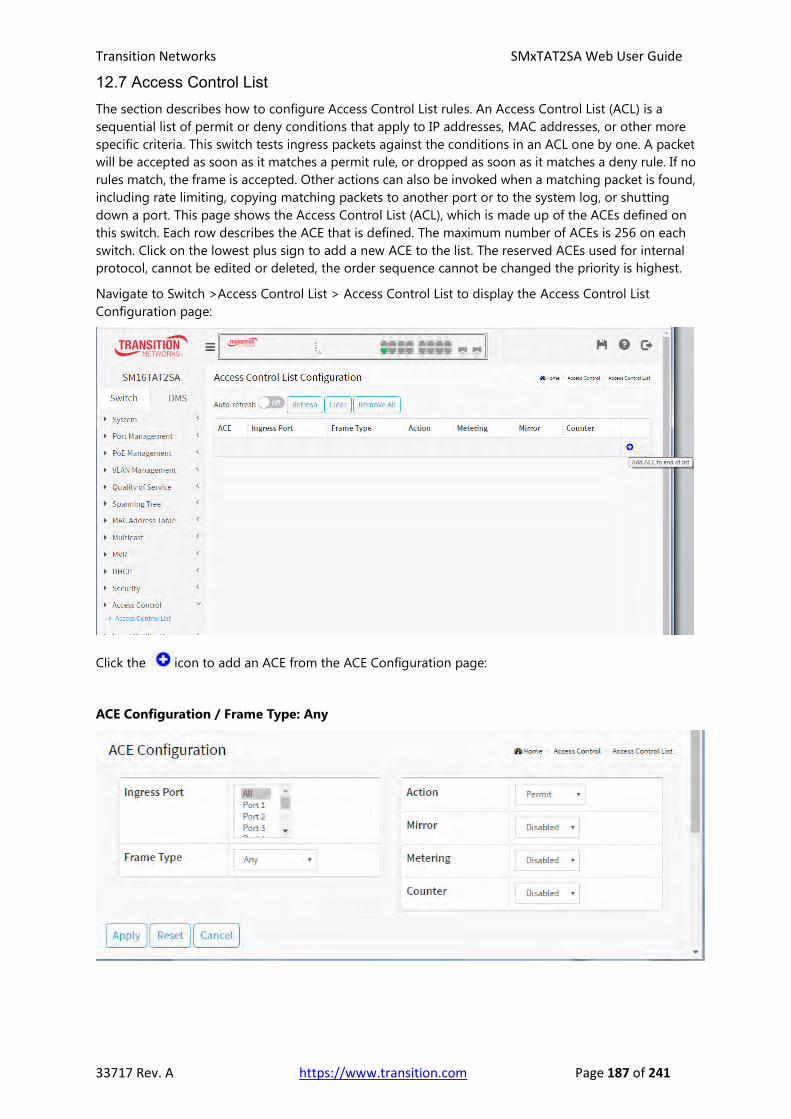
Transition Networks SMxTAT2SA Web User Guide
33717 Rev. A https://www.transition.com Page 187 of 241
12.7 Access Control List The section describes how to configure Access Control List rules. An Access Control List (ACL) is a
sequential list of permit or deny conditions that apply to IP addresses, MAC addresses, or other more
specific criteria. This switch tests ingress packets against the conditions in an ACL one by one. A packet
will be accepted as soon as it matches a permit rule, or dropped as soon as it matches a deny rule. If no
rules match, the frame is accepted. Other actions can also be invoked when a matching packet is found,
including rate limiting, copying matching packets to another port or to the system log, or shutting
down a port. This page shows the Access Control List (ACL), which is made up of the ACEs defined on
this switch. Each row describes the ACE that is defined. The maximum number of ACEs is 256 on each
switch. Click on the lowest plus sign to add a new ACE to the list. The reserved ACEs used for internal
protocol, cannot be edited or deleted, the order sequence cannot be changed the priority is highest.
Navigate to Switch >Access Control List > Access Control List to display the Access Control List
Configuration page:
Click the icon to add an ACE from the ACE Configuration page:
ACE Configuration / Frame Type: Any

Transition Networks SMxTAT2SA Web User Guide
33717 Rev. A https://www.transition.com Page 188 of 241
ACE Configuration / Frame Type: Ethernet Type
ACE Configuration / Frame Type: IPv4

Transition Networks SMxTAT2SA Web User Guide
33717 Rev. A https://www.transition.com Page 189 of 241
ACE Configuration Parameters:
ACE: Indicates the ACE ID.
Ingress Port: Select the ingress port of the ACE. Possible values are:
All: The ACE will match all ingress port.
Port: The ACE will match a specific ingress port.
Frame Type: Indicates the frame type of the ACE. Possible values are:
Any: The ACE will match any frame type.
EType: The ACE will match Ethernet Type frames. Note that an Ethernet Type based ACE will not get
matched by IP and ARP frames.
ARP: The ACE will match ARP/RARP frames.
IPv4: The ACE will match all IPv4 frames.
IPv4/ICMP: The ACE will match IPv4 frames with ICMP protocol.
IPv4/UDP: The ACE will match IPv4 frames with UDP protocol.
IPv4/TCP: The ACE will match IPv4 frames with TCP protocol.
IPv4/Other: The ACE will match IPv4 frames, which are not ICMP/UDP/TCP.
IPv6: The ACE will match all IPv6 standard frames.
Action: Indicates the forwarding action of the ACE. Possible values are:
Permit: Frames matching the ACE may be forwarded and learned.
Deny: Frames matching the ACE are dropped.
Filter: Frames matching the ACE are filtered.
Metering: Enable or disable metering mode. The default value is "Disabled".
Metering Bandwidth: Enter an integer value between 16 and 1000000 Kbps.
Mirror: Specify the mirror operation of this port. Frames matching the ACE are mirrored to the
destination mirror port. The allowed values are: Enabled: Frames received on the port are mirrored.
Disabled: Frames received on the port are not mirrored. The default value is "Disabled".
Counter: The counter indicates the number of times the ACE was hit by a frame.
MAC Parameters
SMAC Filter: Specify the source MAC filter for this ACE. (Only displayed when the frame type is
Ethernet Type or ARP.) Any: No SMAC filter is specified. (SMAC filter status is "don't-care".) Specific: If
you want to filter a specific source MAC address with this ACE, choose this value. A field for entering an
SMAC value displays.
SMAC Value: When "Specific" is selected for the SMAC filter, you can enter a specific source MAC
address. The legal format is "xx-xx-xx-xx-xx-xx" or "xx.xx.xx.xx.xx.xx" or "xxxxxxxxxxxx" (x is a
hexadecimal digit). A frame that hits this ACE matches this SMAC value.
DMAC Filter: Specify the destination MAC filter for this ACE. Any: No DMAC filter is specified. (DMAC
filter status is "don't-care".) MC: Frame must be multicast. BC: Frame must be broadcast. UC: Frame
must be unicast. Specific: If you want to filter a specific destination MAC address with this ACE, choose
this value. A field for entering a DMAC value displays.
DMAC Value: When "Specific" is selected for the DMAC filter, you can enter a specific destination MAC
address. The legal format is "xx-xx-xx-xx-xx-xx" or "xx.xx.xx.xx.xx.xx" or "xxxxxxxxxxxx" (x is a
hexadecimal digit). A frame that hits this ACE matches this DMAC value.

Transition Networks SMxTAT2SA Web User Guide
33717 Rev. A https://www.transition.com Page 190 of 241
VLAN Parameters
802.1Q Tagged: Specify whether frames can hit the action according to the 802.1Q tagged. The
allowed values are: Any: Any value is allowed ("don't-care"). Enabled: Tagged frame only. Disabled:
Untagged frame only. The default value is "Any".
VLAN ID Filter: Specify the VLAN ID filter for this ACE. Any: No VLAN ID filter is specified. (VLAN ID
filter status is "don't-care".) Specific: If you want to filter a specific VLAN ID with this ACE, choose this
value. A field for entering a VLAN ID number displays.
VLAN ID: When "Specific" is selected for the VLAN ID filter, you can enter a specific VLAN ID number.
The valid range is 1 to 4094. A frame that hits this ACE matches this VLAN ID value.
Tag Priority: Specify the tag priority for this ACE. A frame that hits this ACE matches this tag priority.
The valid number range is 0 to 7. The value Any means that no tag priority is specified (tag priority is
"don't-care".)
ARP Parameters
The ARP parameters can be configured when Frame Type "ARP" is selected.
ARP/RARP: Specify the available ARP/RARP opcode (OP) flag for this ACE.
Any: No ARP/RARP OP flag is specified. (OP is "don't-care".)
ARP: Frame must have ARP opcode set to ARP.
RARP: Frame must have RARP opcode set to RARP.
Other: Frame has unknown ARP/RARP Opcode flag.
Request/Reply: Specify the available Request/Reply opcode (OP) flag for this ACE. Any: No
Request/Reply OP flag is specified. (OP is "don't-care".) Request: Frame must have ARP Request or
RARP Request OP flag set. Reply: Frame must have ARP Reply or RARP Reply OP flag.
Sender IP Filter: Specify the sender IP filter for this ACE. Any: No sender IP filter is specified. (Sender IP
filter is "don't-care".) Host: Sender IP filter is set to Host. Specify the sender IP address in the SIP
Address field that appears. Network: Sender IP filter is set to Network. Specify the sender IP address
and sender IP mask in the SIP Address and SIP Mask fields that appear.
Sender IP Address: When "Host" or "Network" is selected for the sender IP filter, you can enter a
specific sender IP address in dotted decimal notation. Notice the invalid IP address configuration is
acceptable too, for example, 0.0.0.0. Normally, an ACE with invalid IP address will explicitly adding deny
action.
Sender IP Mask: When "Network" is selected for the sender IP filter, you can enter a specific sender IP
mask in dotted decimal notation.
Target IP Filter: Specify the target IP filter for this specific ACE. Any: No target IP filter is specified.
(Target IP filter is "don't-care".) Host: Target IP filter is set to Host. Specify the target IP address in the
Target IP Address field that appears. Network: Target IP filter is set to Network. Specify the target IP
address and target IP mask in the Target IP Address and Target IP Mask fields that appear.
Target IP Address: When "Host" or "Network" is selected for the target IP filter, you can enter a specific
target IP address in dotted decimal notation. Notice the invalid IP address configuration is acceptable
too, for example, 0.0.0.0. Normally, an ACE with invalid IP address will explicitly adding deny action.
Target IP Mask: When "Network" is selected for the target IP filter, you can enter a specific target IP
mask in dotted decimal notation.
ARP Sender MAC Match: Specify whether frames can hit the action according to their sender
hardware address field (SHA) settings. 0: ARP frames where SHA is not equal to the SMAC address. 1:
ARP frames where SHA is equal to the SMAC address. Any: Any value is allowed ("don't-care").
Transition Networks SMxTAT2SA Web User Guide
33717 Rev. A https://www.transition.com Page 191 of 241
RARP Target MAC Match: Specify whether frames can hit the action according to their target
hardware address (THA) field settings. 0: RARP frames where THA is not equal to the target MAC
address. 1: RARP frames where THA is equal to the target MAC address. Any: Any value is allowed
("don't-care").
IP/Ethernet Length: Specify whether frames can hit the action according to their ARP/RARP hardware
address length (HLN) and protocol address length (PLN) settings. 0: ARP/RARP frames where the HLN
is not equal to Ethernet (0x06) or the (PLN) is not equal to IPv4 (0x04). 1: ARP/RARP frames where the
HLN is equal to Ethernet (0x06) and the (PLN) is equal to IPv4 (0x04). Any: Any value is allowed
("don't-care").
IP: Specify whether frames can hit the action according to their ARP/RARP hardware address space
(HRD) settings. 0: ARP/RARP frames where the HLD is not equal to Ethernet (1). 1: ARP/RARP frames
where the HLD is equal to Ethernet (1). Any: Any value is allowed ("don't-care").
Ethernet: Specify whether frames can hit the action according to their ARP/RARP protocol address
space (PRO) settings. 0: ARP/RARP frames where the PRO is not equal to IP (0x800). 1: ARP/RARP
frames where the PRO is equal to IP (0x800). Any: Any value is allowed ("don't-care").
IPv4 Parameters
The IP parameters can be configured when Frame Type "IPv4" is selected.
IP Protocol Filter: Specify the IP protocol filter for this ACE. Any: No IP protocol filter is specified
("don't-care"). ICMP: Select ICMP to filter IPv4 ICMP protocol frames. Extra fields for defining ICMP
parameters will appear. These fields are explained later in this section. UDP: Select UDP to filter IPv4
UDP protocol frames. Extra fields for defining UDP parameters will appear. These fields are explained
later in this section. TCP: Select TCP to filter IPv4 TCP protocol frames. Extra fields for defining TCP
parameters will appear. These fields are explained later in this section. Other: If you want to filter
another specific IP protocol filter with this ACE, choose this value. A field for entering an IP protocol
filter displays.
IP Protocol Value: When "Specific" is selected for the IP protocol value, you can enter a specific value.
The valid range is 0 to 255. A frame that hits this ACE matches this IP protocol value.
IP TTL: Specify the Time-to-Live settings for this ACE. Zero: IPv4 frames with a Time-to-Live field
greater than zero must not be able to match this entry. Non-zero: IPv4 frames with a Time-to-Live field
greater than zero must be able to match this entry. Any: Any value is allowed ("don't-care").
IP Fragment: Specify the fragment offset settings for this ACE. This involves the settings for the More
Fragments (MF) bit and the Fragment Offset (FRAG OFFSET) field for an IPv4 frame. No: IPv4 frames
where the MF bit is set or the FRAG OFFSET field is greater than zero must not be able to match this
entry. Yes: IPv4 frames where the MF bit is set or the FRAG OFFSET field is greater than zero must be
able to match this entry. Any: Any value is allowed ("don't-care").
IP Option: Specify the options flag setting for this ACE. No: IPv4 frames where the options flag is set
must not be able to match this entry. Yes: IPv4 frames where the options flag is set must be able to
match this entry. Any: Any value is allowed ("don't-care").
SIP Filter: Specify the source IP filter for this ACE. Any: No source IP filter is specified. (Source IP filter is
"don't-care".) Host: Source IP filter is set to Host. Specify the source IP address in the SIP Address field
that appears. Network: Source IP filter is set to Network. Specify the source IP address and source IP
mask in the SIP Address and SIP Mask fields that appear.
SIP Address: When "Host" or "Network" is selected for the source IP filter, you can enter a specific SIP
address in dotted decimal notation.
SIP Mask: When "Network" is selected for the source IP filter, you can enter a specific SIP mask in
dotted decimal notation.
DIP Filter: Specify the destination IP filter for this ACE. Any: No destination IP filter is specified.
(Destination IP filter is "don't-care".) Host: Destination IP filter is set to Host. Specify the destination IP

Transition Networks SMxTAT2SA Web User Guide
33717 Rev. A https://www.transition.com Page 192 of 241
address in the DIP Address field that appears. Network: Destination IP filter is set to Network. Specify
the destination IP address and destination IP mask in the DIP Address and DIP Mask fields that appear.
DIP Address: When "Host" or "Network" is selected for the DIP Filter, you can enter a specific DIP
address in dotted decimal notation.
DIP Mask: When "Network" is selected for the DIP Filter, you can enter a specific DIP mask in dotted
decimal notation.
IPv6 Parameters
The IPv6 parameters can be configured when Frame Type "IPv6" is selected.
Next Header Filter: Specify the IPv6 next header filter for this ACE. Any: No IPv6 next header filter is
specified ("don't-care"). ICMP: Select ICMP to filter IPv6 ICMP protocol frames. Extra fields for defining
ICMP parameters will appear. These fields are explained later in this section. UDP: Select UDP to filter
IPv6 UDP protocol frames. Extra fields for defining UDP parameters will appear. These fields are
explained later in this section. TCP: Select TCP to filter IPv6 TCP protocol frames. Extra fields for defining
TCP parameters will appear. These fields are explained later in this section. other: If you want to filter a
specific IPv6 next header filter with this ACE, choose this value. A field for entering an IPv6 next header
filter appears.
Next Header Value: When "other" is selected for the IPv6 next header value, you can enter a specific
value. The allowed range is 0 to 255. A frame that hits this ACE matches this IPv6 protocol value.
SIP Filter: Specify the source IPv6 filter for this ACE. Any: No source IPv6 filter is specified. (Source IPv6
filter is "don't-care".) Specific: Source IPv6 filter is set to Network. Specify the source IPv6 address and
source IPv6 mask in the SIP Address fields that appear.
SIP Address (32 bits): When "Specific" is selected for the source IPv6 filter, you can enter a specific
SIPv6 address. The field only supported last 32 bits for IPv6 address.
SIP BitMask (32 bits): When "Specific" is selected for the source IPv6 filter, you can enter a specific
SIPv6 mask. The field only supported last 32 bits for IPv6 address. Notice the usage of bitmask, if the
binary bit value is "0", it means this bit is "don't-care". The real matched pattern is [sipv6_address &
sipv6_bitmask] (last 32 bits). For example, if the SIPv6 address is 2001::3 and the SIPv6 bitmask is
0xFFFFFFFE(bit 0 is "don't-care" bit), then SIPv6 address 2001::2 and 2001::3 are applied to this rule.
Hop Limit: Specify the hop limit settings for this ACE. 0: IPv6 frames with a hop limit field greater than
zero must not be able to match this entry. 1: IPv6 frames with a hop limit field greater than zero must
be able to match this entry. Any: Any value is allowed ("don't-care").

Transition Networks SMxTAT2SA Web User Guide
33717 Rev. A https://www.transition.com Page 193 of 241
ICMP Parameters
ICMP Type Filter: Specify the ICMP filter for this ACE. Any: No ICMP filter is specified (ICMP filter status
is "don't-care"). Specific: If you want to filter a specific ICMP filter with this ACE, you can enter a specific
ICMP value. A field for entering an ICMP value appears.
ICMP Type Value: When "Specific" is selected for the ICMP filter, you can enter a specific ICMP value.
The allowed range is 0 to 255. A frame that hits this ACE matches this ICMP value.
ICMP Code Filter: Specify the ICMP code filter for this ACE. Any: No ICMP code filter is specified (ICMP
code filter status is "don't-care"). Specific: If you want to filter a specific ICMP code filter with this ACE,
you can enter a specific ICMP code value. A field for entering an ICMP code value appears.
ICMP Code Value: When "Specific" is selected for the ICMP code filter, you can enter a specific ICMP
code value. The allowed range is 0 to 255. A frame that hits this ACE matches this ICMP code value.
TCP Parameters
Source Port Filter: Specify the TCP/UDP source filter for this ACE. Any: No TCP/UDP source filter is
specified (TCP/UDP source filter status is "don't-care"). Specific: If you want to filter a specific TCP/UDP
source filter with this ACE, you can enter a specific TCP/UDP source value. A field for entering a
TCP/UDP source value appears. Range: If you want to filter a specific TCP/UDP source range filter with
this ACE, you can enter a specific TCP/UDP source range value. A field for entering a TCP/UDP source
value appears.
Source Port No.: When "Specific" is selected for the TCP/UDP source filter, you can enter a specific
TCP/UDP source value. The allowed range is 0 to 65535. A frame that hits this ACE matches this
TCP/UDP source value.
Source Port Range: When "Range" is selected for the TCP/UDP source filter, you can enter a specific
TCP/UDP source range value. The allowed range is 0 to 65535. A frame that hits this ACE matches this
TCP/UDP source value.
Destination Port Filter: Specify the TCP/UDP destination filter for this ACE. Any: No TCP/UDP
destination filter is specified (TCP/UDP destination filter status is "don't-care"). Specific: If you want to
filter a specific TCP/UDP destination filter with this ACE, you can enter a specific TCP/UDP destination
value. A field for entering a TCP/UDP destination value appears. Range: If you want to filter a specific
range TCP/UDP destination filter with this ACE, you can enter a specific TCP/UDP destination range
value. A field for entering a TCP/UDP destination value displays.
Dest. Port No.: When "Specific" is selected for the TCP/UDP destination filter, you can enter a specific
TCP/UDP destination value. The allowed range is 0 to 65535. A frame that hits this ACE matches this
TCP/UDP destination value.
Destination Port Range: When "Range" is selected for the TCP/UDP destination filter, you can enter a
specific TCP/UDP destination range value. The allowed range is 0 to 65535. A frame that hits this ACE
matches this TCP/UDP destination value.
TCP FIN: One of several TCP flag names used only when filtering TCP (urg, ack, psh, rst, syn, and fin).
Specify the TCP "No more data from sender" (FIN) value for this ACE. 0: TCP frames where the FIN field
is set must not be able to match this entry. 1: TCP frames where the FIN field is set must be able to
match this entry. Any: Any value is allowed ("don't-care").
TCP SYN: One of several TCP flag names used only when filtering TCP (urg, ack, psh, rst, syn, and fin).
Specify the TCP "Synchronize sequence numbers" (SYN) value for this ACE. 0: TCP frames where the
SYN field is set must not be able to match this entry. 1: TCP frames where the SYN field is set must be
able to match this entry. Any: Any value is allowed ("don't-care").
TCP RST: One of several TCP flag names used only when filtering TCP (urg, ack, psh, rst, syn, and fin).
Specify the TCP "Reset the connection" (RST) value for this ACE. 0: TCP frames where the RST field is set
must not be able to match this entry. 1: TCP frames where the RST field is set must be able to match

Transition Networks SMxTAT2SA Web User Guide
33717 Rev. A https://www.transition.com Page 194 of 241
this entry. Any: Any value is allowed ("don't-care").
TCP PSH: One of several TCP flag names used only when filtering TCP (urg, ack, psh, rst, syn, and fin).
Specify the TCP "Push” function (PSH) value for this ACE. 0: TCP frames where the PSH field is set must
not be able to match this entry. 1: TCP frames where the PSH field is set must be able to match this
entry. Any: Any value is allowed ("don't-care").
TCP ACK: One of several TCP flag names used only when filtering TCP (urg, ack, psh, rst, syn, and fin).
Specify the TCP "Acknowledgment field significant" (ACK) value for this ACE. 0: TCP frames where the
ACK field is set must not be able to match this entry. 1: TCP frames where the ACK field is set must be
able to match this entry. Any: Any value is allowed ("don't-care").
TCP URG: One of several TCP flag names used only when filtering TCP (urg, ack, psh, rst, syn, and fin).
Specify the TCP "Urgent Pointer field significant" (URG) value for this ACE. 0: TCP frames where the URG
field is set must not be able to match this entry. 1: TCP frames where the URG field is set must be able
to match this entry. Any: Any value is allowed ("don't-care").
UDP Parameters
Source Port Filter: Specify the TCP/UDP source filter for this ACE. Any: No TCP/UDP source filter is
specified (TCP/UDP source filter status is "don't-care"). Specific: If you want to filter a specific TCP/UDP
source filter with this ACE, you can enter a specific TCP/UDP source value. A field for entering a
TCP/UDP source value appears. Range: If you want to filter a specific TCP/UDP source range filter with
this ACE, you can enter a specific TCP/UDP source range value. A field for entering a TCP/UDP source
value appears.
Source Port No.: When "Specific" is selected for the TCP/UDP source filter, you can enter a specific
TCP/UDP source value. The allowed range is 0 to 65535. A frame that hits this ACE matches this
TCP/UDP source value.
Source Port Range: When "Range" is selected for the TCP/UDP source filter, you can enter a specific
TCP/UDP source range value. The allowed range is 0 to 65535. A frame that hits this ACE matches this
TCP/UDP source value.
Dest. Port Filter: When "Specific" is selected for the TCP/UDP destination filter, you can enter a specific
TCP/UDP destination value. The allowed range is 0 to 65535. A frame that hits this ACE matches this
TCP/UDP destination value.
Destination Port Range: When "Range" is selected for the TCP/UDP destination filter, you can enter a
specific TCP/UDP destination range value. The allowed range is 0 to 65535. A frame that hits this ACE
matches this TCP/UDP destination value.
Ethernet Type Parameters
The Ethernet Type parameters can be configured when Frame Type "Ethernet Type" is selected.
EtherType Filter: Specify the Ethernet type filter for this ACE. Any: No EtherType filter is specified
(EtherType filter status is "don't-care"). Specific: If you want to filter a specific EtherType filter with this
ACE, you can enter a specific EtherType value. A field for entering a EtherType value appears.
Ethernet Type Value: When "Specific" is selected for the EtherType filter, you can enter a specific
EtherType value. The allowed range is 0x600 to 0xFFFF but excluding 0x800(IPv4), 0x806(ARP) and
0x86DD(IPv6). A frame that hits this ACE matches this EtherType value.

Transition Networks SMxTAT2SA Web User Guide
33717 Rev. A https://www.transition.com Page 195 of 241
Access Control List Configuration Example
Control Icons
Add ACE to end of list.
Edit ACE on this line.
Delete ACE on this line.

Transition Networks SMxTAT2SA Web User Guide
33717 Rev. A https://www.transition.com Page 196 of 241
12.8 Event Notification Navigate to the Switch > Event Notification > SNMP Trap menu path to display the SNMP Trap Hosts
Configuration table. Here you can add and configure up to six SNMP Trap hosts.
Click a line to display its configurable parameters:
Parameters:
No: Displays the instance number for this line in the table.
Version: The SNMP version (v2c).
Server IP: Enter the SNMP trap server IP address.
Community Name: Enter the SNMP community name. This is the community access string when
sending SNMP trap packet. The allowed string length is 0 to 255, and the allowed content is ASCII
characters from 33 to 126.
Severity Level: At the dropdown select Emerg, Alert, Crit, Error, Warning, Notice, Info, Debug.
For SNMP traps, configure severity level as Debug. Indicates what kind of message will send to trap
server. Possible modes are:
Emerg: System is unusable.
Alert: Action must be taken immediately.
Crit: Critical conditions.
Error: Error conditions.
Warning: Warning conditions.
Notice: Normal but significant conditions.
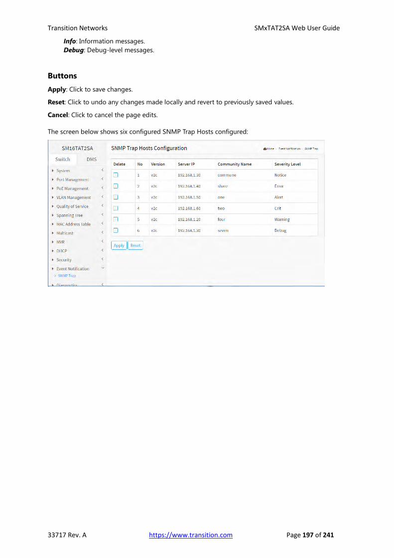
Transition Networks SMxTAT2SA Web User Guide
33717 Rev. A https://www.transition.com Page 197 of 241
Info: Information messages.
Debug: Debug-level messages.
Buttons
Apply: Click to save changes.
Reset: Click to undo any changes made locally and revert to previously saved values.
Cancel: Click to cancel the page edits.
The screen below shows six configured SNMP Trap Hosts configured:

Transition Networks SMxTAT2SA Web User Guide
33717 Rev. A https://www.transition.com Page 198 of 241
Chapter 13 Diagnostics
This chapter provides a set of basic system diagnosis. It let users know that
whether the system is health or needs to be fixed. The basic system
diagnostics include Ping, Cable Diagnostics, Traceroute, and Mirroring.
13-1 Ping
This section lets you issue ICMP PING packets to troubleshoot
IPv4 or IPv6 connectivity issues.
Web Interface
To configure a PING in the web interface:
1. Click Diagnostics and Ping.
2. Specify IP Address, IP Version, and Ping Length and Ping Count.
3. Click Start.
Figure 13-1: ICMP Ping
Parameter descriptions:
IP Address: To set the IP Address of device what you want to ping it.
IP Version: To set the IP Version what you want.
Ping Length: The payload size of the ICMP packet. Values range from 2 bytes to 1452 bytes.
Ping Count: The count of the ICMP packet. Values range from 1 time to 60 times.
Start: Click the “Start” button then the switch will start to ping the device using ICMP packet size what
set on the switch.

Transition Networks SMxTAT2SA Web User Guide
33717 Rev. A https://www.transition.com Page 199 of 241
After you press Start, 5 ICMP packets are transmitted, and the sequence number and roundtrip time
are displayed upon reception of a reply. The page refreshes automatically until responses to all packets
are received, or until a timeout occurs.
Successful Ping: PING 192.168.1.77 (192.168.1.77): 56 data bytes 64 bytes from 192.168.1.77: seq=0 ttl=64 time=0.000 ms 64 bytes from 192.168.1.77: seq=1 ttl=64 time=0.000 ms 64 bytes from 192.168.1.77: seq=2 ttl=64 time=0.000 ms 64 bytes from 192.168.1.77: seq=3 ttl=64 time=0.000 ms 64 bytes from 192.168.1.77: seq=4 ttl=64 time=0.000 ms --- 192.168.1.77 ping statistics --- 5 packets transmitted, 5 packets received, 0% packet loss round-trip min/avg/max = 0.000/0.000/0.000 ms
Failed Ping: PING 192.168.1.32 (192.168.1.32): 56 data bytes Request timed out. Request timed out. Request timed out. Request timed out. Request timed out. --- 192.168.1.32 ping statistics --- 5 packets transmitted, 0 packets received, 100% packet loss
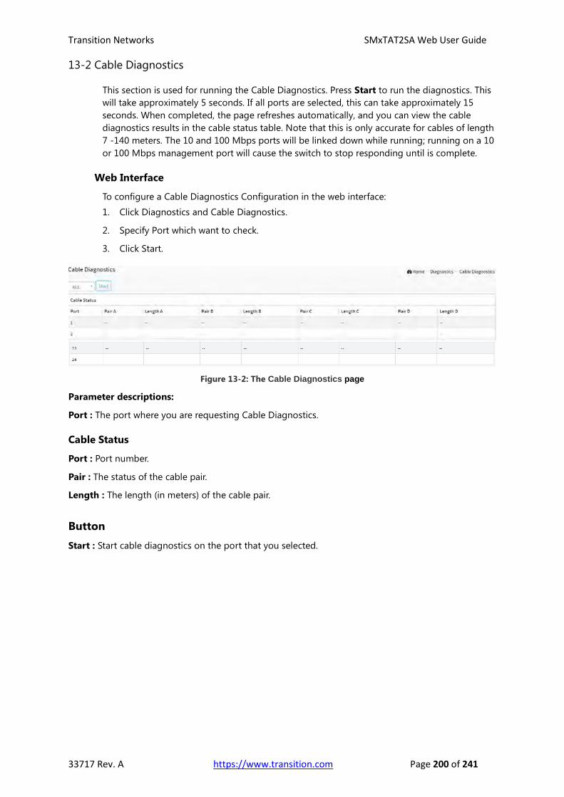
Transition Networks SMxTAT2SA Web User Guide
33717 Rev. A https://www.transition.com Page 200 of 241
13-2 Cable Diagnostics
This section is used for running the Cable Diagnostics. Press Start to run the diagnostics. This
will take approximately 5 seconds. If all ports are selected, this can take approximately 15
seconds. When completed, the page refreshes automatically, and you can view the cable
diagnostics results in the cable status table. Note that this is only accurate for cables of length
7 -140 meters. The 10 and 100 Mbps ports will be linked down while running; running on a 10
or 100 Mbps management port will cause the switch to stop responding until is complete.
Web Interface
To configure a Cable Diagnostics Configuration in the web interface:
1. Click Diagnostics and Cable Diagnostics.
2. Specify Port which want to check.
3. Click Start.
Figure 13-2: The Cable Diagnostics page
Parameter descriptions:
Port : The port where you are requesting Cable Diagnostics.
Cable Status
Port : Port number.
Pair : The status of the cable pair.
Length : The length (in meters) of the cable pair.
Button
Start : Start cable diagnostics on the port that you selected.

Transition Networks SMxTAT2SA Web User Guide
33717 Rev. A https://www.transition.com Page 201 of 241
Cable Diagnostics / Cable Status Normal:
Cable Diagnostics / Cable Status Open / Mismatch:

Transition Networks SMxTAT2SA Web User Guide
33717 Rev. A https://www.transition.com Page 202 of 241
13-3 Traceroute
This page allows you to issue ICMP, TCP, or UDP packets to diagnose network connectivity
issues.
Web Interface
To configure a Traceroute in the web interface:
1. Click Diagnostics and Traceroute.
2. Specify IP Address, IP Version, IP Protocol, traceroute Size.
3. Click Start.
Figure 13-3: The Traceroute page
Parameter descriptions:
IP Address: The destination IP Address.
IP Version: To set the IP Version what you want.
Protocol: The protocol (ICMP, UDP, TCP) packets to send.
Wait Time: Set the time (in seconds) to wait for a response to a probe (default 5.0 sec). Values range
from 1 to 60. The payload size of the ICMP packet. Values range from 2 bytes to 1452 bytes.
Maximum TTL: Specifies the maximum number of hops (max time-to-live value) traceroute will probe.
Values range from 1 to 255. The default is 30.
Probe Count: Sets the number of probe packets per hop. Values range from 1 to 10. The default is 3.
Button
Start: Start traceroute on the port that you selected.

Transition Networks SMxTAT2SA Web User Guide
33717 Rev. A https://www.transition.com Page 203 of 241
13-4 Mirroring
You can mirror traffic from any source port to a target port for real-time analysis. You can then
attach a logic analyzer or RMON probe to the target port and study the traffic crossing the
source port in a completely unobtrusive manner.
Mirror Configuration is used to monitor the traffic of the network. For example, assume that
Port A and Port B are Monitoring Port and Monitored Port respectively; the traffic received by
Port B will be copied to Port A for monitoring.
Web Interface
To configure the Mirror in the web interface:
1. Click Diagnostics and Mirroring.
2. Scroll to select Monitor Destination Port on which port.
3. Scroll to disabled, enable, TX Only and RX only to set the Port mirror mode.
4. Click the Apply button to save the setting.
5. To cancel the setting click the Reset button. It will revert to previously saved values.
Figure 13-4: The Mirror Configuration page
Parameter descriptions:
Mode: Indicates the Mirror mode operation. Possible modes are:
on: Enable Mirror mode operation.
off: Disable Mirror mode operation.
Monitor Destination Port : Port to mirror also known as the mirror port. Frames from ports that have
either source (rx) or destination (tx) mirroring enabled are mirrored on this port. Disabled disables
mirroring.
Transition Networks SMxTAT2SA Web User Guide
33717 Rev. A https://www.transition.com Page 204 of 241
Mirror Source Port Configuration: The following table is used for Rx and Tx enabling.
Port: The logical port for the settings contained in the same row.
Mode: Select mirror mode:
Rx only: Frames received on this port are mirrored on the mirror port. Frames transmitted are not
mirrored.
Tx only: Frames transmitted on this port are mirrored on the mirror port. Frames received are not
mirrored.
Disabled: neither frames transmitted nor frames received are mirrored.
Enabled: Frames received and frames transmitted are mirrored on the mirror port.
NOTE: For a given port, a frame is only transmitted once. So is not possible to mirror Tx
frames on the mirror port. Because of this, the mode for the selected mirror port is
limited to Disabled or Rx only.
Buttons
Apply: Click to save changes.
Reset: Click to undo any changes made locally and revert to previously saved values.

Transition Networks SMxTAT2SA Web User Guide
33717 Rev. A https://www.transition.com Page 205 of 241
Chapter 14 Maintenance
This chapter describes the switch Maintenance configuration tasks to enhance
the performance of local network including Save, Backup, Restore, Activate,
Delete, Restart Device, Factory Defaults, and Firmware upgrade and Firmware
Selection.
14-1 Configuration
The switch stores its configuration in a number of text files in CLI format.
The files are either virtual (RAM-based) or stored in flash on the switch.
There are three system files:
running-config: A virtual file that represents the currently active configuration on the
switch. This file is volatile. The config settings must be different than the default settings.
startup-config: The startup configuration for the switch, read at boot time.
default-config: A read-only file with vendor-specific configuration. This file is read when
the system is restored to default settings.
It is also possible to store up to two other files and apply them to running-config, thereby
switching configuration.
14-1.1 Save startup-config
This will copy the running-config to startup-config, thereby ensuring that the currently active
configuration will be used at the next reboot.
Web Interface
To save running configuration in the web interface:
1. Click Maintenance, Configuration, Save startup-config.
2. Click Save Configuration.
Figure 14-1.1: Save Running Config to Startup Config
Button
Save Configuration: Click to save configuration; the running configuration will be written to flash
memory for system boot up to load this startup configuration file. When done, the message
“startup-config saved successfully.” displays. Note: The generation of the configuration file may be time
consuming, depending on the amount of non-default configuration.

Transition Networks SMxTAT2SA Web User Guide
33717 Rev. A https://www.transition.com Page 206 of 241
14-1.2 Backup Configuration
This section describes how to export the Switch Configuration for maintenance needs. Any
current configuration files will be exported as text format.
If the file system is full (i.e., contains the three system files mentioned above plus two other
files), it is not possible to create new files, but an existing file must be overwritten or another
deleted first.
Web Interface
To download configuration in the web interface:
1. Click Maintenance, Configuration, and Backup.
2. Select running-config, default-config, or startup-config for backup.
3. Click the Backup button. At the prompt select “Save”. Select Open or Save or View
Download.
Figure 14-1.2: Backup Configuration
Parameter descriptions:
Button
Backup : Click the “Backup” button then the switch will start to download the configuration from flash
memory to the PC or Server. Note: running-config may take a while to prepare for download.

Transition Networks SMxTAT2SA Web User Guide
33717 Rev. A https://www.transition.com Page 207 of 241
14-1.3 Restore Configuration
It is possible to upload any of the files on the switch to the web browser. Select the file and
click the Restore button. Upload of running-config may take a little while to complete, as the
file must be prepared for upload. The configuration upload function will be backed up and
saved configuration from the switch’s configuration into the running PC’s web browser.
Web Interface
To restore a configuration via the web interface:
1. Click Maintenance, Configuration, and Restore.
2. Browse to and select a Source File.
3. Click the Restore button.
Figure 14-1.3: Restore Configuration
There are three destination file name selections:
running-config: A virtual file that represents the currently active configuration on the switch. This file
is volatile. You can select “Replace” the existing file, or “Merge” the existing file with the new file.
startup-config: The startup configuration for the switch, read at boot time.
Create new file: A read-only file with vendor-specific configuration. This file is read when the system is
restored to default settings.
Buttons
Browse: Click the “Browse” button to search the configuration text file and filename
Restore: Click the “Restore” button then the running web management PC will start to upload the
configuration from the location PC configuration into the managed switch.
Message: The config file is uploaded successfully.

Transition Networks SMxTAT2SA Web User Guide
33717 Rev. A https://www.transition.com Page 208 of 241
14-1.4 Activate config
It is possible to activate any of the configuration files present on the switch, except for
running-config which represents the currently active configuration.
Select the file to activate and click. This will initiate the process of completely replacing the
existing configuration with that of the selected file.
Web Interface
To activate configuration in the web interface:
1. Click Maintenance, Configuration and Activate Configuration.
2. Select the File Name to be activated.
3. Click the Activate Configuration File button.
Figure 14-1.4: Activate Configuration
Parameter descriptions:
Activate: Click to activate the selected file.
Buttons
Activate Configuration File: Click the button then the selected file will be activated and will become
this switch's running configuration.

Transition Networks SMxTAT2SA Web User Guide
33717 Rev. A https://www.transition.com Page 209 of 241
14-1.5 Delete config
It is possible to delete any of the writable files stored in flash, including startup-config. If this
is done and the switch is rebooted without a prior save operation, this effectively resets the
switch to its default configuration.
Web Interface
To delete configuration in the web interface:
1. Click Maintenance, Configuration, Delete config.
2. Click Delete Select.
Figure 14-1.5: Delete Configuration
Parameter descriptions:
Delete: Select the file that you want to be deleted.
Buttons
Delete Configuration File: Click the button then the selected file will be deleted.
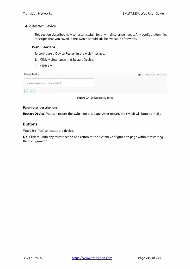
Transition Networks SMxTAT2SA Web User Guide
33717 Rev. A https://www.transition.com Page 210 of 241
14-2 Restart Device
This section describes how to restart switch for any maintenance needs. Any configuration files
or scripts that you saved in the switch should still be available afterwards.
Web Interface
To configure a Device Restart in the web interface:
1. Click Maintenance and Restart Device.
2. Click Yes.
Figure 14-2: Restart Device
Parameter descriptions:
Restart Device: You can restart the switch on this page. After restart, the switch will boot normally.
Buttons
Yes: Click “Yes” to restart the device.
No: Click to undo any restart action and return to the System Configuration page without restarting
the configuration.

Transition Networks SMxTAT2SA Web User Guide
33717 Rev. A https://www.transition.com Page 211 of 241
14-3 Factory Defaults
This section describes how to reset the Switch configuration to Factory Defaults. Any
configuration files or scripts will recover to factory default values.
Web Interface
To reset the switch configuration to its Factory default settings in the web interface:
1. Click Maintenance and Factory Defaults.
2. Check the box if you want to keep the current IP configuration.
3. Click Yes.
Figure 14-3: Restore Config to Factory Defaults
Buttons
Keep IP Configuration: Check if you want to keep the current IP address configuration.
Yes: Click the “Yes” button to reset the configuration to Factory Defaults.
No: Click to undo any restore action and return to the System Configuration page without restoring
the configuration.

Transition Networks SMxTAT2SA Web User Guide
33717 Rev. A https://www.transition.com Page 212 of 241
14-4 Firmware
This section describes how to upgrade and select Firmware. The Switch can be enhanced with
value-added functions by installing firmware upgrades.
14-4.1 Firmware Upgrade
This page facilitates an update of the firmware controlling the switch.
Web Interface
To configure a Firmware Upgrade Configuration in the web interface:
1. Click Maintenance, Firmware, and Firmware Upgrade.
2. Browse to and select the file to upgrade the switch to (e.g.,
SM16TAT2SA_Transition_201702024.tgz).
3. Click the Upload button.
Figure 14-4.1 The Software Upload page
Buttons:
Browse: Click the “Choose File” button to search for the Firmware filename.
NOTE: This page facilitates an update of the firmware controlling the switch. A Software
Upload will update the managed switch to the software image at the specified location.
After the software image is uploaded, a page announces that the firmware update is
initiated. After about a minute, the firmware is updated and the switch restarts.
WARNING: While the firmware is being updated, Web access appears to be defunct. The
front LED flashes Green/Off with a frequency of 10 Hz while the firmware update is in
progress. Do not restart or power off the device at this time or the switch may fail to
function afterwards.
Messages:
Message: Error : The firmware is already update. Meaning: You are trying to upgrade to the current (existing) firmware version. Recovery: Verify that you are upgrading to the latest version.
Message: The firmware update was successful. Meaning: The software was successfully updated. Recovery: None required.

Transition Networks SMxTAT2SA Web User Guide
33717 Rev. A https://www.transition.com Page 213 of 241
Message: Firmware upgrade in progress Waiting, please stand by...
Meaning: While the firmware is being updated, do not restart or power off the switch or it may fail to
function afterwards. Recovery: None. Wait for the upgrade to complete.
Message: Error : The firmware image is invalid. Please use a correct firmware image. Meaning: You tried to upload an invalid firmware file. Recovery: Check the file format and location. Make sure the firmware filename prefix matches your specific switch model (e.g., sm16tat2sa).

Transition Networks SMxTAT2SA Web User Guide
33717 Rev. A https://www.transition.com Page 214 of 241
14-4.1 Firmware Selection
This page lets you activate an alternate firmware image. This page provides information about the
active and alternate (backup) firmware images in the device, and allows you to activate the alternate
image. The web page displays two tables with information about the active and alternate firmware
images.
Parameters:
Active Image
Partition: e.g., “primary” firmware image. Indicates whether primary or secondary partition in the flash is used for storing the firmware image.
Version: The active firmware version (e.g., v1.00.798).
Date: The active firmware build date (Date 2017-02-24 14:09:14 UTC).
Alternate Image Partition: e.g., “secondary” firmware image.
Version: The alternate firmware version (e.g., v0.94.690).
Date: The alternate firmware build date (e.g., 2017-01-24 15:21:49 UTC).
Buttons:
Activate Alternate Image: Click the button to activate the Alternate Firmware image.
Cancel: Click to cancel the page edits.

Transition Networks SMxTAT2SA Web User Guide
33717 Rev. A https://www.transition.com Page 215 of 241
Chapter 15 DMS (Device Management System)
The Transition Networks DMS (Device Management System) is an intelligent
management tool embedded in the switch to intuitively help IT/TS in reducing
support time, cost, and effort. In the SMxTAT2SA main menu pane on the left,
navigate to the DMS tab to display the main DMS features: DMS Mode,
Graphical Monitoring, Management, and Maintenance.
15-1 DMS Mode Click the DMS tab. From the default DMS page (Graphical Monitoring > Topology View) click DMS
Mode to display the DMS Information table:
DMS Information parameters
DMS Mode: At the dropdown select Enabled, Disabled, or High Priority (master).
The default is Enabled.
Total Devices: Displays the total number of discovered devices (e.g., 2).
On-line Devices: Displays the total number of discovered devices that are currently on line (e.g., 2).
Off-line Devices: Displays the total number of discovered devices that are currently off line (e.g., 0).
Controller IP: Displays the configured IP address (e.g., 192.168.1.77).
Buttons
Apply: Click to save changes.

Transition Networks SMxTAT2SA Web User Guide
33717 Rev. A https://www.transition.com Page 216 of 241
15-2 Graphical Monitoring
Navigate to the DMS > Graphical Monitoring menu path to view the options of DMS Graphical
Monitoring, Management, and Maintenance.
15-2.1 Topology View
Navigate to the DMS > Graphical Monitoring > Topology View menu path.
Click the button to display the right pane menu tabs (Device, Group, and Config).
DMS Topology View parameters
Device tab parameters
Devices dropdown: Select the device type (All, SWITCH, PC, IP Camera, IP Phone, AP,
Others, or Off Line).
Snapshot icon: Use the icon to capture the displayed topology view.
File format: Select the graphics file type (SVG, PNG, or PDF).
Search box: Use the to search for a device by typing IP/MAC address or
Model/Device name.

Transition Networks SMxTAT2SA Web User Guide
33717 Rev. A https://www.transition.com Page 217 of 241
Group tab parameters
Vlan ID: Enter a VLAN ID (VID) for the new group (1-4095).
Name: Enter a name for the new group.
OUI 1: Enter an Organizationally Unique Identifier.
OUI 2: Enter a second Organizationally Unique Identifier.
OUI 3: Enter a third Organizationally Unique Identifier.
Apply: Click when done entering the new group data.
Delete: Click to close the new group configuration dialog.
Config tab parameters
Total Device: Displays the total number of devices discovered.
Controller IP: The control device IP address in the format 0.0.0.0.
DHCP Server IP: The IP address of the configured DHCP Server;
otherwise --- if no DHCP Server is configured.
DHCP Server: At the dropdown select Enabled or Disabled.
The default is Disabled.
IP Range: The range type (Single Subnet or Multiple Subnet).
If you select Multiple Subnet, selection fields display for Range 1 -
Range 4.
Apply: Click the button to make the changes.

Transition Networks SMxTAT2SA Web User Guide
33717 Rev. A https://www.transition.com Page 218 of 241
Device data
Click a device in the Topology View to display its captured data:
Device data parameters
Device Type: e.g., SWITCH, PC, IP Camera, IP Phone, AP (Access Point).
Device Name: e.g., SM16TAT2SA
Model Name: e.g., SM16TAT2SA
Mac Address: e.g., 00-40-c7-1c-cb-6e
IP Address: e.g., 192.168.1.77
Http port: e.g., 80
PoE Supply: e.g., 0 Watts
Login icon: Click to display the login window.
Upgrade icon: Click to display a window in which you can enter a Tftp Server IP address and the name
of a firmware file to upgrade to.
Find Switch icon: Click to flash the device LEDs for 15 seconds to help find the device. Click OK to clear
the message.
PoE Config icon: Click to display a window in which you can enable or disable PoE Auto Checking
globally, and enable or disable PoE Mode on a port-by-port basis.
Dashboard icon: Click to display the dashboard.
Notification icon: Click to display an editable message area.
Unknown Device parameters
You can click on an unknown device ( ) to display its discovered
data (see descriptions above):

Transition Networks SMxTAT2SA Web User Guide
33717 Rev. A https://www.transition.com Page 219 of 241
15-2.3 DMS Firmware Upgrade Procedure
1. Navigate to the DMS > Graphical Monitoring > Topology View menu path.
2. Click the button to display the right pane menu tabs (Entry and Config).
3. Connect all switches and make sure DMS is working.
- Set all switches with different IP address and in the same IP segment
- Make sure gateway IP address is configured.
4. Enable the TFTP server and set the correct image path.
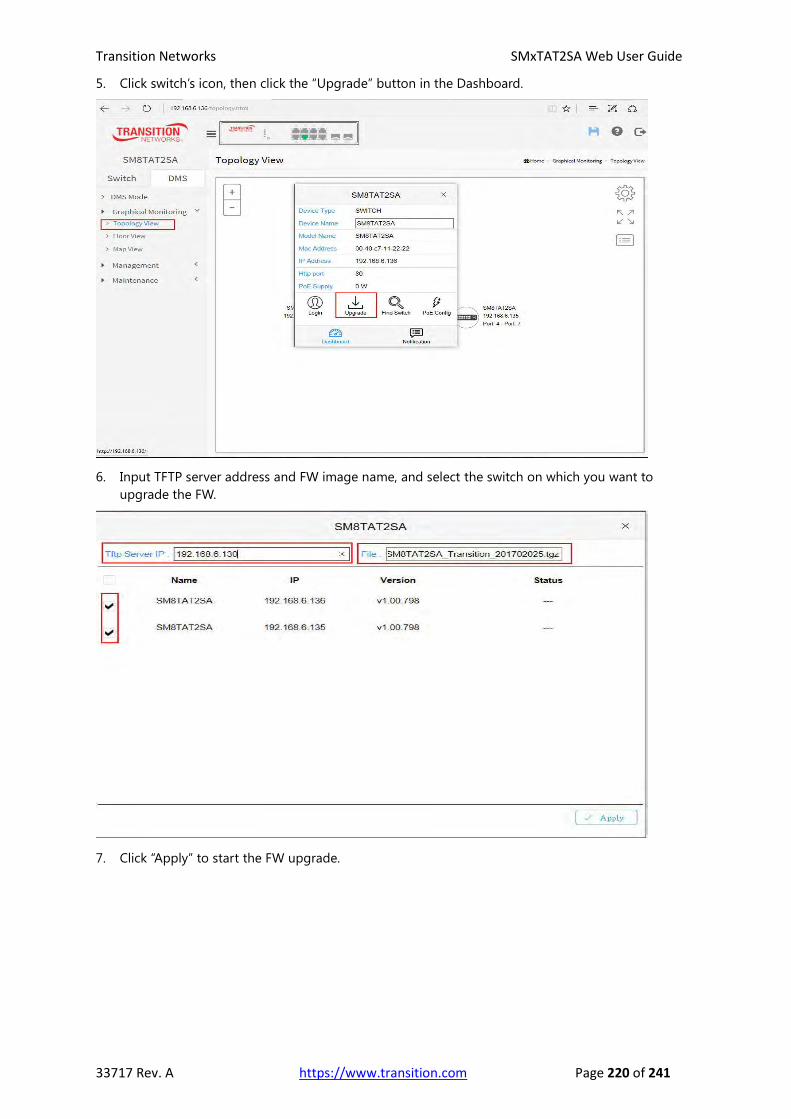
Transition Networks SMxTAT2SA Web User Guide
33717 Rev. A https://www.transition.com Page 220 of 241
5. Click switch’s icon, then click the “Upgrade” button in the Dashboard.
6. Input TFTP server address and FW image name, and select the switch on which you want to
upgrade the FW.
7. Click “Apply” to start the FW upgrade.

Transition Networks SMxTAT2SA Web User Guide
33717 Rev. A https://www.transition.com Page 221 of 241
8. Observe the upgrade status until completion.

Transition Networks SMxTAT2SA Web User Guide
33717 Rev. A https://www.transition.com Page 222 of 241
15-2.4 Floor View
Navigate to the DMS > Graphical Monitoring > Floor View menu path.
Click the button to display the right pane menu tabs (Entry and Config).
DMS Floor View parameters
Device tab parameters
Devices dropdown: Select the device type (All, SWITCH, PC, IP Camera, IP Phone, AP, Others, or
Off Line).
Snapshot icon: Use the icon to capture the displayed topology view.
File format: Select the graphics file type (SVG, PNG, or PDF).
Search box: Use the to search for a device by typing IP/MAC
address or Model/Device name.
Config tab parameters
Total Device: Displays the total number of devices discovered.
Controller IP: The control device IP address in the format 0.0.0.0.
IP Range: The range type (Single Subnet or Multiple Subnet).
Apply: Click the button to save the selections.

Transition Networks SMxTAT2SA Web User Guide
33717 Rev. A https://www.transition.com Page 223 of 241
15-2.5 Map View
Navigate to the DMS > Graphical Monitoring > Floor View menu path.
Click the button to display the right pane menu tabs (Device and Config).
The message “192.168.1.77 wants to know your location” displays.
Click the Allow button.
DMS Map View parameters
Device tab:
Devices dropdown: Select the device type (All, SWITCH, PC, IP Camera, IP Phone, AP, Others, or Off
Line).
Search box: Use the to search for a device by typing IP/MAC address or
Model/Device name.
Config tab parameters:
Total Device: Displays the total number of devices discovered.
Controller IP: The control device IP address in the format 0.0.0.0.
IP Range: The range type (Single Subnet or Multiple Subnet).
Apply: Click the button to save the selections.

Transition Networks SMxTAT2SA Web User Guide
33717 Rev. A https://www.transition.com Page 224 of 241
Satellite View: From DMS > Graphical Monitoring > Map View you can click Satellite to replace the
Map View with a satellite view:

Transition Networks SMxTAT2SA Web User Guide
33717 Rev. A https://www.transition.com Page 225 of 241
15-3 Management
Navigate to DMS > Management > Device List to show all devices and their information which are
detected by DMS.
DMS > Management > Device List parameters
Remove: Check the box to delete the table entry at the next Apply.
Status: e.g., Online or Offline.
Device Type: e.g., SWITCH or Others.
Model Name: e.g., SM8TAT2SA or SM16TAT2SA or SM24TAT2SA.
Device Name: e.g., SM8TAT2SA or SM16TAT2SA or SM24TAT2SA.
MAC: e.g., 00-40-C7-1C-CB-6E.
IP Address: e.g., 192.168.1.77.
Buttons
Auto-refresh: Select on to automatically refresh the page every 3 seconds. The default is off.
Refresh: Click the button to refresh the page immediately.
Edit: Click the button to display the table in editable form. Click this icon to Edit Device Name and http
Port. You can press "Edit" icon to edit device name for each IP device. This function can also be
configured in the Dashboard of Topology view. There is no HTTP connection function for Unknown
Device and PC type devices, so UI doesn't provide "Edit HTTP port" function for configuring it.
Show xx entries: At the dropdown select how many entries to show per page (10, 25, 60, or All).
Search: Enter key word(s) to search for on the page.
Remove: Only Offline devices provide "Remove" function to remove from DMS device list.
Previous: Click to display the previous set of entries (if any exist).
Next: Click to display the next set of entries (if any exist).
Apply: Click to save changes.

Transition Networks SMxTAT2SA Web User Guide
33717 Rev. A https://www.transition.com Page 226 of 241
15-4 Maintenance
Navigate to DMS > Maintenance > Floor Image:
DMS > Maintenance > Floor Image parameters
Maximum: The maximum number of files available for use.
Used: The number of file(s) used.
Free: The number of file(s) free for use.
Add Floor Image: Click Choose File and browse to and select a File Name to add.
Add: Click to add the selected file.
Select: Displays the selected image name.
No.: Displays the instance number.
File Name: Displays the selected file name.
Image: Displays the selected image. Image added (Floor Plan for FloorPlan1):
Message: 192.168.1.77 says: Insufficient Space. Only x files available.
Meaning: The file is too large or no file exists.
Recovery: Click the OK button to clear the message and choose a new File Name to add.

Transition Networks SMxTAT2SA Web User Guide
33717 Rev. A https://www.transition.com Page 227 of 241
Appendix A Troubleshooting, Warranty, Support
and Compliance
Refer to the SMxTAT2SA Install Guide for Install Troubleshooting, Warranty, Support, and Compliance information.
General Troubleshooting Procedure
Many problems are caused by the following situations. Check for these items first when you start troubleshooting:
1. Verify the install procedures were performed correctly. See the SMxTAT2SA Install Guide.
2. Check if the SMxTAT2SA POWER LED is Off:
Check connections between the switch, the power cord and the wall outlet.
Contact your dealer for assistance.
3. Check if the SMxTAT2SA Link LED is Off:
Verify that the switch and attached device are powered on.
Be sure the cable is plugged into the switch and corresponding device.
If the switch is installed in a rack, check the connections to the punch-down block and patch panel.
Verify that the proper cable type is used and its length does not exceed specified limits.
Check the adapter on the attached device and cable connections for possible defects. Replace the defective adapter or cable if necessary.
4. Make sure all devices connected to the SMxTAT2SA are configured to auto negotiate, or are configured to connect at half duplex (all hubs are configured this way, for example).
5. Check the cabling: Look for faulty or loose cables. Look for non-standard and miswired cables.
6. Make sure you have a valid network topology: Check for improper Network Topologies. Make sure that your network topology contains no data path loops.
7. Check the port configuration. Make sure ports have not been put into a “blocking” state by Spanning Tree, GVRP, or LACP.
The normal operation of the Spanning Tree, GVRP, and LACP features may put the port in a blocking state.
Verify that the port has not been configured as disabled via software.
8. Make sure connected devices (e.g., SFPs, switches, hubs) are cabled, powered, and operating properly.
9. If possible, try switching modes (i.e., from Web UI to CLI, or vice versa).
10. Verify the specific function that failed (e.g., port config, PoE or VLAN management, QoS, Spanning Tree). Refer to the specific function's user manual page and online Help for details. Verify that the function you are trying to perform is supported by your particular switch model.
11. Run the tests in the Diagnostic tab of the Web UI. Verify that the interface is assigned to the correct VLAN. Use the Layer 2 traceroute. Check for spanning-tree problems such as BPDU floods or flapping mac address. Try a ping to broadcast IP address of subnet from your L3 device (Gateway).

Transition Networks SMxTAT2SA Web User Guide
33717 Rev. A https://www.transition.com Page 228 of 241
12. Record any related error messages, conditions, and configurations for your Tech Support Specialist to consider. See below.
13. Contact Transition Networks Tech Support. See below.
Record Device and System Information After performing the troubleshooting procedures, and before calling or emailing Technical Support, please record as much information as possible in order to help the Transition Networks Tech Support Specialist.
1. Select the SMxTAT2SA Configuration > System > Information menu path. From the CLI, use the show commands needed to gather the information below or as requested by the TN Support Specialist.
2. Record SMxTAT2SA Model Information: Product ID: _________________________________
Serial #: ____________________________ Board Rev: _________________________________
MAC Address: _____________________ Chip ID: ______________________________________
System Uptime: _____________________ Software Version: ______________________________
3. Record the Monitor menu information:
Monitor > System > Information: ____________________________________________________
Monitor > System > IP Status: _______________________________________________________
LED Status: ________________________________________________________________________
__________________________________________________________________________________
4. Provide additional information to your Tech Support Specialist. See the “Troubleshooting” section above.
Your Transition Networks service contract number: _______________________________________
A description of the failure: __________________________________________________________
_________________________________________________________________________________
__________________________________________________________________________________ __________________________________________________________________________________
A description of any action(s) already taken to resolve the problem (e.g., changing mode, rebooting, etc.): ____________________________________________________________________________
_________________________________________________________________________________
_________________________________________________________________________________ __________________________________________________________________________________
The serial and revision numbers of all involved Transition Networks products in the network: __________________________________________________________________________________
__________________________________________________________________________________
A description of your network environment (layout, cable type, etc.): _________________________
__________________________________________________________________________________
__________________________________________________________________________________
Network load and frame size at the time of trouble (if known): ______________________________

Transition Networks SMxTAT2SA Web User Guide
33717 Rev. A https://www.transition.com Page 229 of 241
The device history (i.e., have you returned the device before, is this a recurring problem, etc.): __________________________________________________________________________________
__________________________________________________________________________________
__________________________________________________________________________________
__________________________________________________________________________________
Previous Return Material Authorization (RMA) numbers: ____________________________________
__________________________________________________________________________________
Serial Label on Box
Contact Us Transition Networks Inc. 10900 Red Circle Drive, Minnetonka, MN 55343 Telephone: +1-952-941-7600 / Toll Free: 800-526-9267 / Fax: 952-941-2322 E-Mail: [email protected] / [email protected]

Transition Networks SMxTAT2SA Web User Guide
33717 Rev. A https://www.transition.com Page 230 of 241
Glossary of Terms
Note that mention of a term below does not imply that the feature described is necessarily supported.
A
ACE
An ACE (Access Control Entry) describes access permission associated with a particular ACE ID.
There are three ACE frame types (Ethernet Type, ARP, and IPv4) and two ACE actions (permit and deny).
The ACE also contains many detailed, different parameter options that are available for individual
application.
ACL
An ACL (Access Control List) is the list table of ACEs, containing access control entries that specify
individual users or groups permitted or denied to specific traffic objects, such as a process or a
program.
Each accessible traffic object contains an identifier to its ACL. The privileges determine whether there
are specific traffic object access rights.
ACL implementations can be quite complex, for example, when the ACEs are prioritized for the various
situation. In networking, the ACL refers to a list of service ports or network services that are available
on a host or server, each with a list of hosts or servers permitted or denied to use the service. ACL can
generally be configured to control inbound traffic, and in this context, they are similar to firewalls.
There are 3 web-pages associated with the manual ACL configuration:
ACL > Access Control List: The web page shows the ACEs in a prioritized way, highest (top) to lowest
(bottom). Default the table is empty. An ingress frame will only get a hit on one ACE even though there
are more matching ACEs. The first matching ACE will take action (permit/deny) on that frame and a
counter associated with that ACE is incremented. An ACE can be associated with a Policy, 1 ingress port,
or any ingress port (the whole switch). If an ACE Policy is created then that Policy can be associated
with a group of ports under the "Ports" web-page. There are number of parameters that can be
configured with an ACE. Read the Web page help text to get further information for each of them. The
maximum number of ACEs is 64.
ACL > Ports: The ACL Ports configuration is used to assign a Policy ID to an ingress port. This is useful
to group ports to obey the same traffic rules. Traffic Policy is created under the "Access Control List" -
page. You can you also set up specific traffic properties (Action / Rate Limiter / Port copy, etc.) for each
ingress port. They will though only apply if the frame gets past the ACE matching without getting
matched. In that case a counter associated with that port is incremented. See the Web page help text
for each specific port property.
ACL > Rate Limiters: Under this page you can configure the rate limiters. There can be 15 different rate
limiters, each ranging from 1-1024K packets per seconds. Under "Ports" and "Access Control List"
web-pages you can assign a Rate Limiter ID to the ACE(s) or ingress port(s).
AES
The AES (Advanced Encryption Standard) encryption key protocol is applied in 802.1i standard to
improve WLAN security. It is an encryption standard by the U.S. government, which will replace DES
and 3DES. AES has a fixed block size of 128 bits and a key size of 128, 192, or 256 bits.
Aggregation
Using multiple ports in parallel to increase the link speed beyond the limits of a port and to increase
the redundancy for higher availability. (Also Port Aggregation, Link Aggregation).
ARP
ARP (Address Resolution Protocol) is a protocol that is used to convert an IP address into a physical
address, such as an Ethernet address. ARP allows a host to communicate with other hosts when only
the Internet address of its neighbors is known. Before using IP, the host sends a broadcast ARP request

Transition Networks SMxTAT2SA Web User Guide
33717 Rev. A https://www.transition.com Page 231 of 241
containing the Internet address of the desired destination system.
ARP Inspection
ARP Inspection is a secure feature. Several types of attacks can be launched against a host or devices
connected to Layer 2 networks by "poisoning" the ARP caches. This feature is used to block such
attacks. Only valid ARP requests and responses can go through the switch device.
Auto-Negotiation
Auto-negotiation is the process where two different devices establish the mode of operation and the
speed settings that can be shared by those devices for a link.
D
DEI
DEI is an acronym for Drop Eligible Indicator. It is a 1-bit field in the VLAN tag.
DES
DES ( Data Encryption Standard) provides a complete description of a mathematical algorithm for
encrypting (enciphering) and decrypting (deciphering) binary coded information. Encrypting data
converts it to an unintelligible form called cipher. Decrypting cipher converts the data back to its
original form called plaintext. The algorithm described in this standard specifies both enciphering and
deciphering operations which are based on a binary number called a key.
DHCP
The DHCP (Dynamic Host Configuration Protocol) is used for assigning dynamic IP addresses to
devices on a network. DHCP used by networked computers (clients) to obtain IP addresses and other
parameters such as the default gateway, subnet mask, and IP addresses of DNS servers from a DHCP
server. The DHCP server ensures that all IP addresses are unique, for example, no IP address is assigned
to a second client while the first client's assignment is valid (its lease has not expired). Therefore, IP
address pool management is done by the server and not by a human network administrator.
Dynamic addressing simplifies network administration because the software keeps track of IP
addresses rather than requiring an administrator to manage the task. This means that a new computer
can be added to a network without the hassle of manually assigning it a unique IP address.
DHCP Relay
DHCP Relay is used to forward and to transfer DHCP messages between the clients and the server
when they are not on the same subnet domain. The DHCP option 82 enables a DHCP relay agent to
insert specific information into a DHCP request packets when forwarding client DHCP packets to a
DHCP server and remove the specific information from a DHCP reply packets when forwarding server
DHCP packets to a DHCP client. The DHCP server can use this information to implement IP address or
other assignment policies. Specifically the option works by setting two suboptions: Circuit ID (option 1)
and Remote ID (option2). The Circuit ID sub-option is supposed to include information specific to
which circuit the request came in on. The Remote ID sub-option was designed to carry information
relating to the remote host end of the circuit.
The definition of Circuit ID in the switch is 4 bytes in length and the format is "vlan_id" "module_id"
"port_no". The parameter of "vlan_id" is the first two bytes represent the VLAN ID. The parameter of
"module_id" is the third byte for the module ID (in standalone switch it always equal 0). The parameter
of "port_no" is the fourth byte and it means the port number. The Remote ID is 6 bytes in length, and
the value is equal the DHCP relay agents MAC address.
DHCP Snooping
DHCP Snooping is used to block intruder on the untrusted ports of the switch device when it tries to
intervene by injecting a bogus DHCP reply packet to a legitimate conversation between the DHCP
client and server.
Transition Networks SMxTAT2SA Web User Guide
33717 Rev. A https://www.transition.com Page 232 of 241
DNS
DNS (Domain Name System) stores and associates many types of information with domain names.
Most importantly, DNS translates human-friendly domain names and computer hostnames into
computer-friendly IP addresses. For example, the domain name www.example.com might translate to
192.168.0.1.
DoS
In a DoS (Denial of Service) attack, an attacker attempts to prevent legitimate users from accessing
information or services. By targeting at network sites or network connection, an attacker may be able
to prevent network users from accessing email, web sites, online accounts (banking, etc.), or other
services that rely on the affected computer.
Dotted Decimal Notation
Dotted Decimal Notation refers to a method of writing IP addresses using decimal numbers and dots
as separators between octets. An IPv4 dotted decimal address has the form x.y.z.w, where x, y, z, and w
are decimal numbers between 0 and 255.
DSCP
DSCP (Differentiated Services Code Point)is a field in the header of IP packets for packet classification
purposes.
E
EEE
EEE is an abbreviation for Energy Efficient Ethernet defined in IEEE 802.3az.
Ethernet Type
Ethernet Type, or EtherType, is a field in the Ethernet MAC header, defined by the Ethernet networking
standard. It is used to indicate which protocol is being transported in an Ethernet frame.
F
FTP
FTP is an acronym for File Transfer Protocol. It is a transfer protocol that uses the Transmission Control
Protocol (TCP) and provides file writing and reading. It also provides directory service and security
features.
Fast Leave
Multicast snooping Fast Leave processing allows the switch to remove an interface from the
forwarding-table entry without first sending out group specific queries to the interface. The VLAN
interface is pruned from the multicast tree for the multicast group specified in the original leave
message. Fast-leave processing ensures optimal bandwidth management for all hosts on a switched
network, even when multiple multicast groups are in use simultaneously. This processing applies to
IGMP and MLD.

Transition Networks SMxTAT2SA Web User Guide
33717 Rev. A https://www.transition.com Page 233 of 241
H
HTTP
HTTP (Hypertext Transfer Protocol) is a protocol that used to transfer or convey information on the
World Wide Web (WWW). HTTP defines how messages are formatted and transmitted, and what
actions Web servers and browsers should take in response to various commands. The other main
standard that controls how the World Wide Web works is HTML, which covers how Web pages are
formatted and displayed. Any Web server machine contains, in addition to the Web page files it can
serve, an HTTP daemon, a program that is designed to wait for HTTP requests and handle them when
they arrive. The Web browser is an HTTP client, sending requests to server machines. An HTTP client
initiates a request by establishing a Transmission Control Protocol (TCP) connection to a particular port
on a remote host (port 80 by default). An HTTP server listening on that port waits for the client to send
a request message.
HTTPS
HTTPS (Hypertext Transfer Protocol over Secure Socket Layer) is used to indicate a secure HTTP
connection. HTTPS provide authentication and encrypted communication and is widely used on the
World Wide Web for security-sensitive communication such as payment transactions and corporate
logons. HTTPS is really just the use of Netscape's Secure Socket Layer (SSL) as a sub layer under its
regular HTTP application layering. (HTTPS uses port 443 instead of HTTP port 80 in its interactions with
the lower layer, TCP/IP.) SSL uses a 40-bit key size for the RC4 stream encryption algorithm, which is
considered an adequate degree of encryption for commercial exchange.
I
ICMP
ICMP (Internet Control Message Protocol) is a protocol that generated the error response, diagnostic or
routing purposes. ICMP messages generally contain information about routing difficulties or simple
exchanges such as time-stamp or echo transactions.
IEEE 802.1X
IEEE 802.1X is an IEEE standard for port-based Network Access Control. It provides authentication to
devices attached to a LAN port, establishing a point-to-point connection or preventing access from
that port if authentication fails. With 802.1X, access to all switch ports can be centrally controlled from
a server, which means that authorized users can use the same credentials for authentication from any
point within the network.
IGMP
IGMP (Internet Group Management Protocol) is a communications protocol used to manage the
membership of Internet Protocol multicast groups. IGMP is used by IP hosts and adjacent multicast
routers to establish multicast group memberships. It is an integral part of the IP multicast specification,
like ICMP for unicast connections. IGMP can be used for online video and gaming, and allows more
efficient use of resources when supporting these uses.
IGMP Querier
A router sends IGMP Query messages onto a particular link. This router is called the Querier.
IMAP
IMAP ( Internet Message Access Protocol) is a protocol for email clients to retrieve email messages
from a mail server. IMAP is the protocol that IMAP clients use to communicate with the servers, and
SMTP is the protocol used to transport mail to an IMAP server. The current version of the Internet
Message Access Protocol is IMAP4. It is similar to Post Office Protocol version 3 (POP3), but offers
additional and more complex features. For example, the IMAP4 protocol leaves your email messages
on the server rather than downloading them to your computer. If you wish to remove your messages
from the server, you must use your mail client to generate local folders, copy messages to your local

Transition Networks SMxTAT2SA Web User Guide
33717 Rev. A https://www.transition.com Page 234 of 241
hard drive, and then delete and expunge the messages from the server.
IP
IP (Internet Protocol) is a protocol used for communicating data across an internet network. IP is a
"best effort" system, which means that no packet of information sent over is assured to reach its
destination in the same condition it was sent. Each device connected to a Local Area Network (LAN) or
Wide Area Network (WAN) is given an Internet Protocol address, and this IP address is used to identify
the device uniquely among all other devices connected to the extended network. The current version
of the Internet protocol is IPv4, which has 32-bits Internet Protocol addresses allowing for in excess of
four billion unique addresses. This number is reduced drastically by the practice of webmasters taking
addresses in large blocks, the bulk of which remain unused. There is a rather substantial movement to
adopt a new version of the Internet Protocol, IPv6, which would have 128-bits Internet Protocol
addresses. This number can be represented roughly by a three with thirty-nine zeroes after it. However,
IPv4 is still the protocol of choice for most of the Internet.
IPMC
IPMC is an acronym for IP Multicast.
IP Source Guard
IP Source Guard is a secure feature used to restrict IP traffic on DHCP snooping untrusted ports by
filtering traffic based on the DHCP Snooping Table or manually configured IP Source Bindings. It helps
prevent IP spoofing attacks when a host tries to spoof and use the IP address of another host.
L
LACP
LACP is an IEEE 802.3ad standard protocol. The Link Aggregation Control Protocol, allows bundling
several physical ports together to form a single logical port.
Lightly Managed Switch (AKA, Smart Switch)
This Ethernet switch category offers certain levels of Management, QoS, Security, etc. with somewhat
“lighter” capabilities and scalability than the Managed switches. This makes Lightly Managed switches a
cost-effective alternative to Managed switches. Lightly Managed switches fit well at the edge of a large
network; Managed Switches are better suited in the core. Lightly Managed switches are also used in
infrastructures with smaller deployments, or for generally less complex networks.
The capabilities available for the Lightly Managed switch category vary, but most have a browser-based
Management interface, often with CLI and/or SNMP. Lightly Managed switches let you segment a
network into workgroups by creating VLANs, but with fewer VLANs and nodes than with a Managed
switch. Lightly Managed switches offer some levels of security, such as 802.1x endpoint authentication,
and/or a limited set of Access Control Lists (ACLs). Lightly Managed switches support basic QoS
(Quality Of Service) that lets you prioritize users and applications per 802.1q/TOS/DSCP.
Transition Networks' SMxTAT2SA switches are included in this Lightly Managed Switch (Smart Switch)
category.
LLC
The IEEE 802.2 Logical Link Control (LLC) protocol provides a link mechanism for upper layer protocols.
It is the upper sub-layer of the Data Link Layer and provides multiplexing mechanisms that make it
possible for several network protocols (IP, IPX) to coexist within a multipoint network. LLC header
consists of 1 byte DSAP (Destination Service Access Point), 1 byte SSAP (Source Service Access Point), 1
or 2 bytes Control field followed by LLC information.

Transition Networks SMxTAT2SA Web User Guide
33717 Rev. A https://www.transition.com Page 235 of 241
LLDP
LLDP is an IEEE 802.1ab standard protocol. The Link Layer Discovery Protocol (LLDP) specified in this
standard allows stations attached to an IEEE 802 LAN to advertise, to other stations attached to the
same IEEE 802 LAN, the major capabilities provided by the system incorporating that station, the
management address or addresses of the entity or entities that provide management of those
capabilities, and the identification of the stations point of attachment to the IEEE 802 LAN required by
those management entity or entities. The information distributed via this protocol is stored by its
recipients in a standard Management Information Base (MIB), making it possible for the information to
be accessed by a Network Management System (NMS) using a management protocol such as the
Simple Network Management Protocol (SNMP).
LLDP-MED
LLDP-MED is an extension of IEEE 802.1ab and is defined by the telecommunication industry
association (TIA-1057). LLDP-MED provides Auto-discovery of LAN policies enabling plug and play
networking, device location discovery to allow VoIP Enhanced 911 services; extended and automated
power management of PoE end points.
M
MAC Table
Switching of frames is based upon the DMAC address contained in the frame. The switch builds up a
table that maps MAC addresses to switch ports for knowing which ports the frames should go to
(based upon the DMAC address in the frame ). This table contains both static and dynamic entries.
The static entries are configured by the network administrator if the administrator wants to do a fixed
mapping between the DMAC address and switch ports.
The frames also contain a MAC address (SMAC address), which shows the MAC address of the
equipment sending the frame. The SMAC address is used by the switch to automatically update the
MAC table with these dynamic MAC addresses. Dynamic entries are removed from the MAC table if no
frame with the corresponding SMAC address have been seen after a configurable age time.
MD5
MD5 (Message-Digest algorithm 5) is a message digest algorithm, used cryptographic hash function
with a 128-bit hash value. It was designed by Ron Rivest in 1991. MD5 is officially defined in RFC 1321 -
The MD5 Message-Digest Algorithm.
Metering
Metering is a service model that an Internet service provider (ISP) uses to track bandwidth usage and
then charges high traffic customers accordingly. Typically, a customer will select a service package with
a flat rate up to a specified limit and then pays additional fees beyond that limit (e.g., per gigabyte of
data downloaded). AKA, bandwidth metering, Internet metering.
Mirroring
For debugging network problems or monitoring network traffic, the switch system can be configured
to mirror frames from multiple ports to a mirror port. (In this context, mirroring a frame is the same as
copying the frame.) Both incoming (source) and outgoing (destination) frames can be mirrored to the
mirror port.
MLD
MLD (Multicast Listener Discovery) for IPv6 is used by IPv6 routers to discover multicast listeners on a
directly attached link, much as IGMP is used in IPv4. The protocol is embedded in ICMPv6 instead of
using a separate protocol.

Transition Networks SMxTAT2SA Web User Guide
33717 Rev. A https://www.transition.com Page 236 of 241
MVR
Multicast VLAN Registration is a protocol for Layer 2 (IP)-networks that lets multicast-traffic from a
source VLAN be shared with subscriber-VLANs. The main reason to use MVR is to save bandwidth by
preventing duplicate multicast streams being sent in the core network; instead stream(s) are received
on the MVRVLAN and forwarded to the VLANs where hosts have requested them (Wikipedia).
N
NAS
NAS (Network Access Server) is meant to act as a gateway to guard access to a protected source.
A client connects to the NAS, and the NAS connects to another resource asking whether the client's
supplied credentials are valid. Based on the answer, the NAS then allows or disallows access to the
protected resource. An example of a NAS implementation is IEEE 802.1X.
NBNS
(NetBIOS Name Service); often called WINS on Windows systems. The NBNS is part of the
NetBIOS-over-TCP protocol suite. NBNS serves a purpose similar to DNS (translate human-readable
names to IP addresses).
NetBIOS
NetBIOS (Network Basic Input/Output System) is a program that allows applications on separate
computers to communicate within a Local Area Network (LAN), and it is not supported on a Wide Area
Network (WAN). The NetBIOS giving each computer in the network both a NetBIOS name and an IP
address corresponding to a different host name, provides the session and transport services described
in the Open Systems Interconnection (OSI) model.
NFS
NFS ( Network File System) allows hosts to mount partitions on a remote system and use them as
though they are local file systems. NFS allows the system administrator to store resources in a central
location on the network, providing authorized users continuous access to them, which means NFS
supports sharing of files, printers, and other resources as persistent storage over a computer network.
NTP
NTP (Network Time Protocol) is a network protocol for synchronizing the clocks of computer systems.
NTP uses UDP (datagram) as transport layer.
O
ONVIF
(originally an acronym for Open Network Video Interface Forum) is a global and open industry forum
with the goal of facilitating the development and use of a global open standard for the interface of
physical IP-based security products (i.e., to create a standard for how IP products in video surveillance
and other physical security areas can communicate with each other).
Optional TLVs
An LLDP frame contains multiple TLVs For some TLVs it is configurable if the switch shall include the
TLV in the LLDP frame. These TLVs are known as optional TLVs. If an optional TLVs is disabled the
corresponding information is not included in the LLDP frame.
OUI
OUI is the organizationally unique identifier. An OUI address is a globally unique identifier assigned to
a vendor by IEEE. You can determine which vendor a device belongs to according to the OUI address
which forms the first 24 bits of a MAC address.

Transition Networks SMxTAT2SA Web User Guide
33717 Rev. A https://www.transition.com Page 237 of 241
P
PCP
PCP (Priority Code Point) is a 3-bit field storing the priority level for the 802.1Q frame. It is also known
as User Priority.
PD
PD is an acronym for Powered Device. In a PoE> system the power is delivered from a PSE ( power
sourcing equipment ) to a remote device. The remote device is called a PD.
PHY
PHY is an abbreviation for Physical Interface Transceiver and is the device that implement the Ethernet
physical layer (IEEE-802.3).
PING
Ping is a program that sends a series of packets over a network or the Internet to a specific computer in
order to generate a response from that computer. The other computer responds with an
acknowledgment that it received the packets. Ping was created to verify whether a specific computer
on a network or the Internet exists and is connected. ping uses Internet Control Message Protocol
(ICMP) packets. The PING Request is the packet from the origin computer, and the PING Reply is the
packet response from the target.
PoE
PoE (Power over Ethernet) is used to transmit electrical power, to remote devices over standard
Ethernet cable. It could for example be used for powering IP telephones, wireless LAN access points
and other equipment, where it would be difficult or expensive to connect the equipment to main
power supply.
Policer
A policer can limit the bandwidth of received frames. It is located in front of the ingress queue.
POP3
POP3 (Post Office Protocol version 3) is a protocol for email clients to retrieve email messages from a
mail server. POP3 is designed to delete mail on the server as soon as the user has downloaded it.
However, some implementations allow users or an administrator to specify that mail be saved for some
period of time. POP can be thought of as a "store-and-forward" service. An alternative protocol is
Internet Message Access Protocol (IMAP). IMAP provides the user with more capabilities for retaining
e-mail on the server and for organizing it in folders on the server. IMAP can be thought of as a remote
file server. POP and IMAP deal with the receiving of e-mail and are not to be confused with the Simple
Mail Transfer Protocol (SMTP). You send e-mail with SMTP, and a mail handler receives it on your
recipient's behalf. Then the mail is read using POP or IMAP. IMAP4 and POP3 are the two most
prevalent Internet standard protocols for e-mail retrieval. Virtually all modern e-mail clients and servers
support both.
Private VLAN
In a private VLAN, communication between ports in that private VLAN is not permitted. A VLAN can be
configured as a private VLAN.
Transition Networks SMxTAT2SA Web User Guide
33717 Rev. A https://www.transition.com Page 238 of 241
Q
QCE
QCE (QoS Control Entry) describes QoS class associated with a particular QCE ID. There are six QCE
frame types: Ethernet Type, VLAN, UDP/TCP Port, DSCP, TOS, and Tag Priority. Frames can be classified
by one of 4 different QoS classes: "Low", "Normal", "Medium", and "High" for individual application.
QCL
QCL (QoS Control List) is the list table of QCEs, containing QoS control entries that classify to a specific
QoS class on specific traffic objects. Each accessible traffic object contains an identifier to its QCL. The
privileges determine specific traffic object to specific QoS class.
QoS
QoS (Quality of Service) is a method to guarantee a bandwidth relationship between individual
applications or protocols. A communications network transports a multitude of applications and data,
including high-quality video and delay-sensitive data such as real-time voice. Networks must provide
secure, predictable, measurable, and sometimes guaranteed services. Achieving the required QoS
becomes the secret to a successful end-to-end business solution. Therefore, QoS is the set of
techniques to manage network resources.
R
RARP
RARP (Reverse Address Resolution Protocol) is a protocol that is used to obtain an IP address for a
given hardware address, such as an Ethernet address. RARP is the complement of ARP.
RADIUS
RADIUS is an acronym for Remote Authentication Dial In User Service. It is a networking protocol that
provides centralized access, authorization and accounting management for
people or computers to connect and use a network service.
RSTP
In 1998, the IEEE with document 802.1w introduced an evolution of STP: the Rapid Spanning Tree
Protocol, which provides for faster spanning tree convergence after a topology change. Standard IEEE
802.1D-2004 now incorporates RSTP and obsoletes STP, while at the same time being backwards
compatible with STP.
S
SHA
SHA (Secure Hash Algorithm) was designed by the National Security Agency (NSA) and published by
the NIST as a U.S. Federal Information Processing Standard. Hash algorithms compute a fixed-length
digital representation (known as a message digest) of an input data sequence (the message) of any
length.
Shaper
A shaper can limit the bandwidth of transmitted frames. It is located after the ingress queues.
Smart Switch (AKA, Lightly Managed Switch)
This category of switches offers certain levels of Management, QoS, Security, etc. with somewhat
“lighter” capabilities and scalability than the Managed switches. This makes them a cost-effective
alternative to Managed switches. Smart switches fit well at the edge of a large network; Managed
Switches are better suited in the core. Smart switches are also used in infrastructures with smaller
deployments, or for generally less complex networks.

Transition Networks SMxTAT2SA Web User Guide
33717 Rev. A https://www.transition.com Page 239 of 241
The capabilities available for the Smart switch category vary, but most have a browser-based
Management interface, often with CLI and/or SNMP. Smart switches let you segment a network into
workgroups by creating VLANs, but with fewer VLANs and nodes than with a Managed switch. Smart
switches offer some levels of security, such as 802.1x endpoint authentication, and/or a limited set of
Access Control Lists (ACLs). Smart switches support basic QoS (Quality Of Service) that lets you
prioritize users and applications per 802.1q/TOS/DSCP.
Transition Networks' SMxTAT2SA switches are included in this Smart Switch (Lightly Managed Switch)
category.
SMTP
SMTP (Simple Mail Transfer Protocol) is a text-based protocol that uses the Transmission Control
Protocol (TCP) and provides a mail service modeled on the FTP file transfer service. SMTP transfers mail
messages between systems and notifications regarding incoming mail.
SNAP
The Sub Network Access Protocol (SNAP) is a mechanism for multiplexing, on networks using IEEE
802.2 LLC, more protocols than can be distinguished by the 8-bit 802.2 Service Access Point (SAP) fields.
SNAP supports identifying protocols by Ethernet type field values; it also supports vendor private
protocol identifier.
SNMP
SNMP (Simple Network Management Protocol) is part of the Transmission Control Protocol/Internet
Protocol (TCP/IP) protocol for network management. SNMP allow diverse network objects to
participate in a network management architecture. It enables network management systems to learn
network problems by receiving traps or change notices from network devices implementing SNMP.
SNTP
SNTP (Simple Network Time Protocol) is a network protocol for synchronizing the clocks of computer
systems. SNTP uses UDP (datagrams) as transport layer.
SSID
Service Set Identifier is a name used to identify the particular 802.11 wireless LANs to which a user
wants to attach. A client device will receive broadcast messages from all access points within range
advertising their SSIDs, and can choose one to connect to based on pre-configuration, or by displaying
a list of SSIDs in range and asking the user to select one (Wikipedia).
SSH
SSH (Secure Shell) is a network protocol that allows data to be exchanged using a secure channel
between two networked devices. The encryption used by SSH provides confidentiality and integrity of
data over an insecure network. The goal of SSH was to replace the earlier rlogin, TELNET and rsh
protocols, which did not provide strong authentication or guarantee confidentiality (Wikipedia).
STP
Spanning Tree Protocol is an OSI layer-2 protocol which ensures a loop free topology for any bridged
LAN. The original STP protocol is now obsolete by RSTP.

Transition Networks SMxTAT2SA Web User Guide
33717 Rev. A https://www.transition.com Page 240 of 241
T
TACACS+
TACACS+ (Terminal Access Controller Access Control System Plus) is a networking protocol which
provides access control for routers, network access servers and other networked computing devices via
one or more centralized servers. TACACS+ provides separate authentication, authorization and
accounting services.
Tag Priority
Tag Priority is a 3-bit field storing the priority level for the 802.1Q frame.
TCP
TCP (Transmission Control Protocol) is a communications protocol that uses the Internet Protocol (IP) to
exchange the messages between computers. The TCP protocol guarantees reliable and in-order
delivery of data from sender to receiver and distinguishes data for multiple connections by concurrent
applications (for example, Web server and e-mail server) running on the same host. The applications
on networked hosts can use TCP to create connections to one another. It is known as a
connection-oriented protocol, which means that a connection is established and maintained until such
time as the message or messages to be exchanged by the application programs at each end have been
exchanged. TCP is responsible for ensuring that a message is divided into the packets that IP manages
and for reassembling the packets back into the complete message at the other end. Common network
applications that use TCP include the World Wide Web (WWW), e-mail, and File Transfer Protocol (FTP).
TELNET (or Telnet or telnet)
TELNET (TELetype NETwork) is a terminal emulation protocol that uses the Transmission Control
Protocol (TCP) and provides a virtual connection between TELNET server and TELNET client.
TFTP
TFTP (Trivial File Transfer Protocol) is a transfer protocol that uses the User Datagram Protocol (UDP)
and provides file writing and reading, but it does not provide directory service and security features.
U
UDP
UDP (User Datagram Protocol) is a communications protocol that uses the Internet Protocol (IP) to
exchange the messages between computers. UDP is an alternative to the Transmission Control Protocol
(TCP) that uses the Internet Protocol (IP). Unlike TCP, UDP does not provide the service of dividing a
message into packet datagrams, and UDP doesn't provide reassembling and sequencing of the packets.
This means that the application program that uses UDP must be able to make sure that the entire
message has arrived and is in the right order. Network applications that want to save processing time
because they have very small data units to exchange may prefer UDP to TCP. UDP provides two services
not provided by the IP layer. It provides port numbers to help distinguish different user requests and,
optionally, a checksum capability to verify that the data arrived intact. Common network applications
that use UDP include the Domain Name System (DNS), streaming media applications such as IPTV,
Voice over IP (VoIP), and Trivial File Transfer Protocol (TFTP).
User Priority
User Priority is a 3-bit field storing the priority level for the 802.1Q frame. It is also known as PCP.

Transition Networks SMxTAT2SA Web User Guide
33717 Rev. A https://www.transition.com Page 241 of 241
V
VLAN
A Virtual LAN is method to restrict communication between switch ports. VLANs can be used for the
following applications:
VLAN unaware switching: This is the default configuration. All ports are VLAN unaware with Port VLAN
ID 1 and members of VLAN 1. This means that MAC addresses are learned in VLAN 1, and the switch
does not remove or insert VLAN tags.
VLAN aware switching: This is based on the IEEE 802.1Q standard. All ports are VLAN aware. Ports
connected to VLAN aware switches are members of multiple VLANs and transmit tagged frames. Other
ports are members of one VLAN, set up with this Port VLAN ID, and transmit untagged frames.
Provider switching: This is also known as Q-in-Q switching. Ports connected to subscribers are VLAN
unaware, members of one VLAN, and set up with this unique Port VLAN ID. Ports connected to the
service provider are VLAN aware, members of multiple VLANs, and set up to tag all frames. Untagged
frames received on a subscriber port are forwarded to the provider port with a single VLAN tag.
Tagged frames received on a subscriber port are forwarded to the provider port with a double VLAN
tag.
VLAN ID
A VLAN ID is a 12-bit field specifying the VLAN to which the frame belongs.
Voice VLAN
Voice VLAN is VLAN configured specially for voice traffic. By adding the ports with voice devices
attached to voice VLAN, we can perform QoS-related configuration for voice data, ensuring the
transmission priority of voice traffic and voice quality.

Transition Networks SMxTAT2SA Web User Guide
33717 Rev. A https://www.transition.com Page 242 of 241
Transition Networks 10900 Red Circle Drive Minnetonka, MN 55343, U.S.A. tel: +1.952.941.7600 | toll free: 1.800.526.9267 | fax: 952.941.2322 [email protected] | [email protected] | [email protected]
Copyright © 2017 Transition Networks. All rights reserved. Printed in the U.S.A.
33717_A - SMxTAT2SA Web User Guide