slider door installation instructions - bathrooms.com different blade seal, lengths supplied. use...
TRANSCRIPT

IMPORTANT: If installing a Slider Door and Side Panel only; ie. a corner installation, please referto alternative fixing details on the document reverse.
Slider DoorInstallation Instructions
• Instruction suitable for both Right and Left Hand fixing variations.
Please note: Enclosure shown is for illustration purposes only. IN00445 (rev B)
2 YEAR GUARANTEE
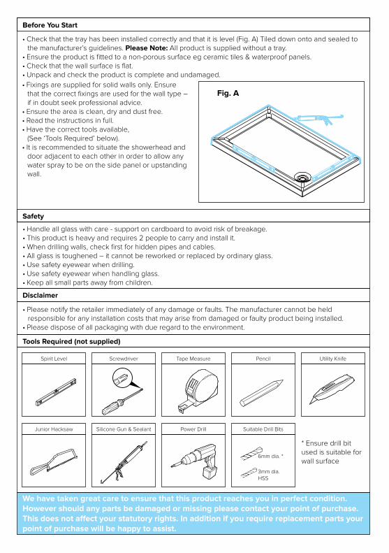
• Check that the tray has been installed correctly and that it is level (Fig. A) Tiled down onto and sealed to the manufacturer’s guidelines. Please Note: All product is supplied without a tray.
• Ensure the product is fitted to a non-porous surface eg ceramic tiles & waterproof panels.• Check that the wall surface is flat.• Unpack and check the product is complete and undamaged.
• Handle all glass with care - support on cardboard to avoid risk of breakage.• This product is heavy and requires 2 people to carry and install it.• When drilling walls, check first for hidden pipes and cables.• All glass is toughened – it cannot be reworked or replaced by ordinary glass.• Use safety eyewear when drilling.• Use safety eyewear when handling glass.• Keep all small parts away from children.
Safety
• Please notify the retailer immediately of any damage or faults. The manufacturer cannot be held responsible for any installation costs that may arise from damaged or faulty product being installed.
• Please dispose of all packaging with due regard to the environment.
Disclaimer
Before You Start
Tools Required (not supplied)
Fig. A
Spirit Level Screwdriver Tape Measure
Junior Hacksaw
Pencil Utility Knife
Silicone Gun & Sealant Power Drill Suitable Drill Bits
6mm dia. *
3mm dia. HSS
* Ensure drill bit used is suitable for wall surface
• Fixings are supplied for solid walls only. Ensure that the correct fixings are used for the wall type – if in doubt seek professional advice.
• Ensure the area is clean, dry and dust free.• Read the instructions in full.• Have the correct tools available,
(See ‘Tools Required’ below).• It is recommended to situate the showerhead and
door adjacent to each other in order to allow any water spray to be on the side panel or upstanding wall.
We have taken great care to ensure that this product reaches you in perfect condition. However should any parts be damaged or missing please contact your point of purchase. This does not affect your statutory rights. In addition if you require replacement parts your point of purchase will be happy to assist.

Parts & Fittings Supplied
Please notify the retailer immediately of any damage or faults. The manufacturer cannot be held responsible for any installation costs that may arise from a damaged or faulty product being installed.
!Keep small parts away from children!
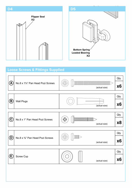
D4
D1 D2
D3
D5
Fixed PanelX1
Glass DoorX1
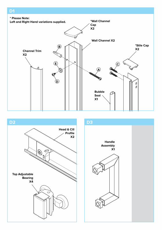
Top AdjustableBearing
X4
Head & Cill Profile
X2
Wall Channel X2
A
D2
D1
*Stile CapX2
Channel TrimX2
*Wall Channel CapX2
B
C
D
E
Bubble SealX1
* Please Note:Left and Right Hand variations supplied.
Handle Assembly
X1
D3
(actual size)
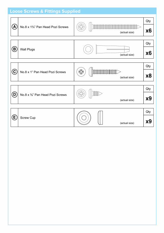
No.8 x 1” Pan Head Pozi Screws Cx8
Qty
No.8 x 1¾” Pan Head Pozi Screws (actual size)
(actual size)
(actual size)
Ax6
Qty
Wall PlugsBx6
Qty
No.8 x ⅜” Pan Head Pozi ScrewsDx6
Qty
(actual size)
Screw CupEx6
Qty
Flipper SealX2
Bottom Spring Loaded Bearing
X2
Loose Screws & Fittings Supplied
D5D4

C
1.1
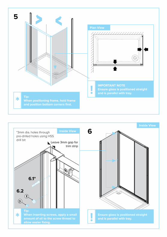
Tip: Assemble frame vertically.*
1.2
Ensure Glass Side Panels are located into pre-fitted glass holders as shown.!
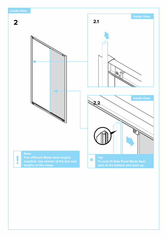
Inside View
Tip: When inserting screws, apply a small amount of oil to the screw thread to allow easier fixing.
*
C

2.1
2.2
2
Note: Two different Blade Seal, lengths supplied. Use shorter of the two seal lengths at this stage.
! Tip: To push fit Side Panel Blade Seal, start at the bottom and work up.*
Inside View
Inside View
Inside View

3.1
3.2 3.3
Please Note: Position one Wall Channel and mark. Ensure Wall Channel is level and in correct location to the tray. (If in doubt refer to illustration on step 4).
!
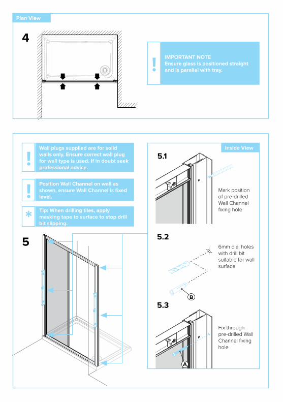
5
5.1
5.2
5.3B
A
4
Plan View
IMPORTANT NOTEEnsure glass is positioned straight and is parallel with tray. !
Inside View
6mm dia. holes with drill bit suitable for wall surface
Mark position of pre-drilled Wall Channel fixing hole
Fix through pre-drilled Wall Channel fixing hole
Wall plugs supplied are for solid walls only. Ensure correct wall plug for wall type is used. If in doubt seek professional advice.
!Position Wall Channel on wall as shown, ensure Wall Channel is fixed level. !Tip: When drilling tiles, apply masking tape to surface to stop drill bit slipping.*
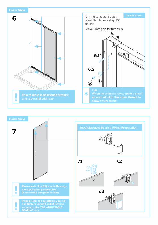
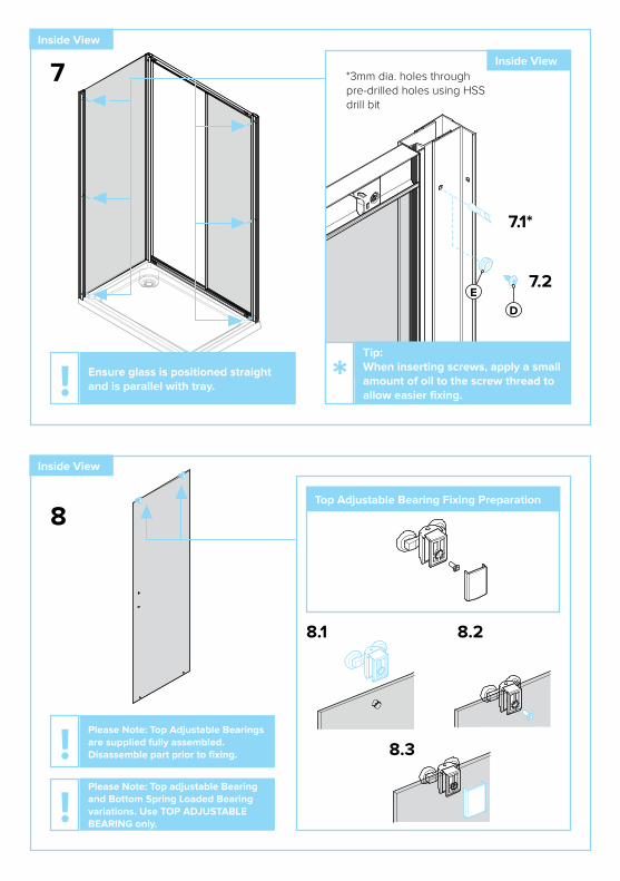
7
7.1 7.2
7.3
Top Adjustable Bearing Fixing Preparation
Inside View
Please Note: Top Adjustable Bearings are supplied fully assembled. Disassemble part prior to fixing.!Please Note: Top adjustable Bearing and Bottom Spring Loaded Bearing variations. Use TOP ADJUSTABLE BEARING only.!
ED
6
Inside View
Inside View
Tip: When inserting screws, apply a small amount of oil to the screw thread to allow easier fixing.
*
6.1*
6.2
*3mm dia. holes through pre-drilled holes using HSS drill bit
Ensure glass is positioned straight and is parallel with tray. !
Leave 3mm gap for trim strip

8.1 8.2
8.3Please Note: Bottom Spring Loaded Bearings are supplied fully assembled. Disassemble part prior to fixing.!Please Note: Bottom Spring Loaded Bearing and Top adjustable Bearing variations. Use BOTTOM SPRING LOADED BEARING only.!
Bottom Spring Loaded Bearing Fixing Preparation
Inside View
8
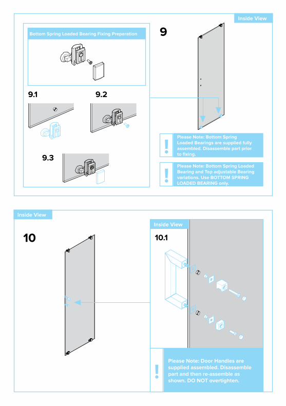
Please Note: Door Handles are supplied assembled. Disassemble part and then re-assemble as shown. DO NOT overtighten.
!
Inside View
9Inside View
9.1

Tip: Locate bearing wheels on the top rail first.*
Inside View
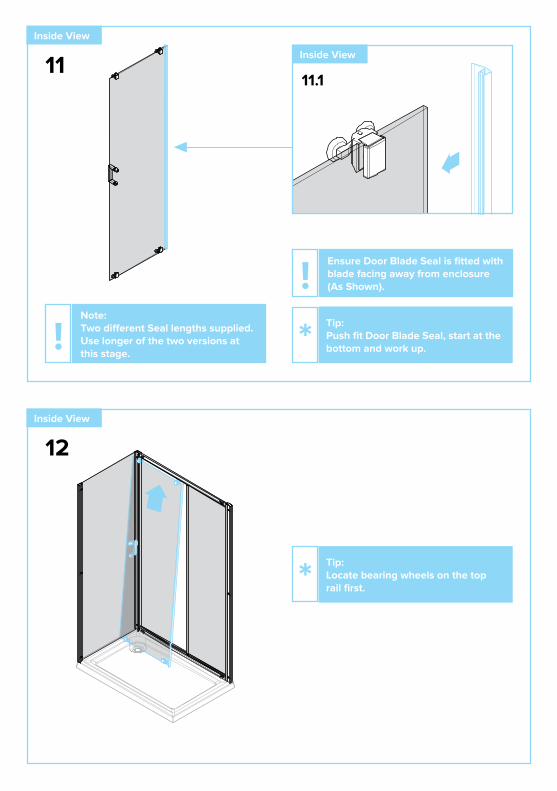
11
Inside View
10Inside View
Note: Two different Seal lengths supplied. Use longer of the two versions at this stage.
!
Ensure Door Blade Seal is fitted with blade facing away from enclosure (as Shown).!Tip: Push fit Door Blade Seal, start at the bottom and work up.*
10.1

12.1
12.2
Inside View
13Inside, Underside View
Tip: When door is correctly positioned, door position can be adjusted up and down using Top Bearing adjustment screws (above).
*Ensure free movement of door. Adjust to suit.!
Inside View
Inside View
Bottom bearings are sprungloaded, push them down so they fitinto the bottom cill rail.*
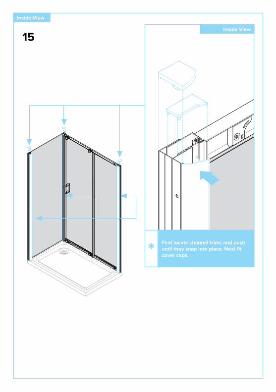
12
Inside View
Inside View
First position channel trims and pushuntil they snap into place. Then fitcover caps.*
13

14
Apply Silicone Sealant (not supplied).!Only apply silicone sealant to the inside verticals where the Wall Channels meet the wall.!

150mm
15
Apply Silicone Sealant (not supplied).!Product Care: Use a non-abrasive cleaner. Water marks may be removed with a proprietary limescale remover or household vinegar.
*

Notes:Notes:

Notes:Notes:
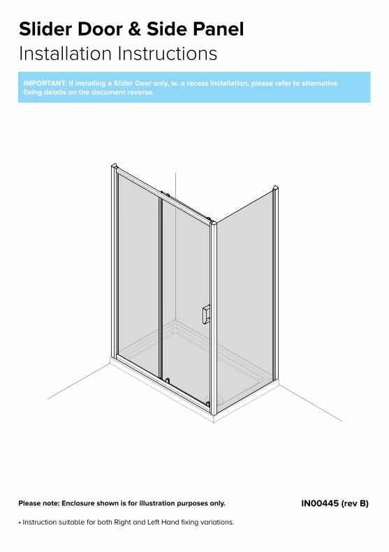
IMPORTANT: If installing a Slider Door only, ie. a recess installation, please refer to alternativefixing details on the document reverse.
Slider Door & Side PanelInstallation Instructions
• Instruction suitable for both Right and Left Hand fixing variations.
Please note: Enclosure shown is for illustration purposes only. IN00445 (rev B)

• Check that the tray has been installed correctly and that it is level (Fig. A) Tiled down onto and sealed to the manufacturer’s guidelines. Please Note: All product is supplied without a tray.
• Ensure the product is fitted to a non-porous surface eg ceramic tiles & waterproof panels.• Check that the wall surface is flat.• Unpack and check the product is complete and undamaged.
• Handle all glass with care - support on cardboard to avoid risk of breakage.• This product is heavy and requires 2 people to carry and install it.• When drilling walls, check first for hidden pipes and cables.• All glass is toughened – it cannot be reworked or replaced by ordinary glass.• Use safety eyewear when drilling.• Use safety eyewear when handling glass.• Keep all small parts away from children.
Safety
• Please notify the retailer immediately of any damage or faults. The manufacturer cannot be held responsible for any installation costs that may arise from damaged or faulty product being installed.
• Please dispose of all packaging with due regard to the environment.
Disclaimer
Before You Start
Tools Required (not supplied)
Fig. A
Spirit Level Screwdriver Tape Measure
Junior Hacksaw
Pencil Utility Knife
Silicone Gun & Sealant Power Drill Suitable Drill Bits
6mm dia. *
3mm dia. HSS
* Ensure drill bit used is suitable for wall surface
• Fixings are supplied for solid walls only. Ensure that the correct fixings are used for the wall type – if in doubt seek professional advice.
• Ensure the area is clean, dry and dust free.• Read the instructions in full.• Have the correct tools available,
(See ‘Tools Required’ below).• It is recommended to situate the showerhead and
door adjacent to each other in order to allow any water spray to be on the side panel or upstanding wall.
We have taken great care to ensure that this product reaches you in perfect condition. However should any parts be damaged or missing please contact your point of purchase. This does not affect your statutory rights. In addition if you require replacement parts your point of purchase will be happy to assist.

Parts & Fittings Supplied
Please notify the retailer immediately of any damage or faults. The manufacturer cannot be held responsible for any installation costs that may arise from a damaged or faulty product being installed.
!Keep small parts away from children!
Side PanelX1
Glass Panel AssemblyX1
Glass DoorX1
D2
D1
D3
D4
D6
D5
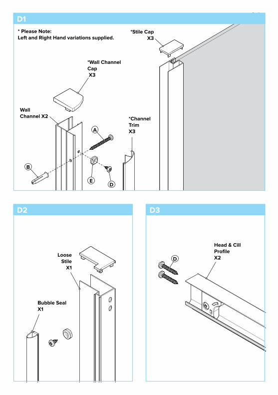
A
Wall Channel X2
E
D
D1
D3D2
*Wall ChannelCap X3
B
D
*Stile Cap X3
*Channel TrimX3
* Please Note:Left and Right Hand variations supplied.
Bubble SealX1
Loose Stile
X1
Head & Cill ProfileX2
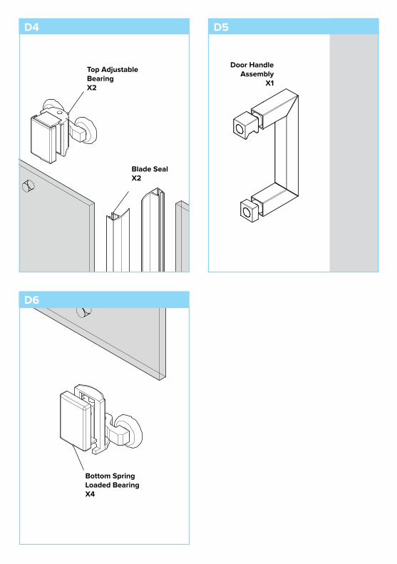
Top Adjustable BearingX2
Door Handle Assembly
X1
D4 D5
D6
Blade SealX2
Bottom SpringLoaded BearingX4
(actual size)
No.8 x 1” Pan Head Pozi Screws Cx8
Qty
No.8 x 1¾” Pan Head Pozi Screws (actual size)
(actual size)
(actual size)
Ax6
Qty
Wall PlugsBx6
Qty
No.8 x ⅜” Pan Head Pozi ScrewsDx9
Qty
(actual size)
Screw CupEx9
Qty
Loose Screws & Fittings Supplied

Fix through pre-drilled holes
C
1.1
Fix through pre-drilled holes
Tip: Assemble frame vertically.*
1.2
Ensure Glass Side Panels are located in pre-fitted glass holders as shown.!
Inside View
Tip: When inserting screws, apply a small amount of oil to the screw thread to allow easier fixing.
*
C
2.1
2.2
2
Note: Two different Blade Seal lengths supplied. Use shorter of the two seal lengths at this stage.
! Tip: To push fit Side Panel Blade Seal, start at the bottom and work up.*
Inside View
Inside View
Inside View

3.1
3.2
Plan View
3
Mark Wall Channel position.
IMPORTANT NOTEEnsure glass is positioned straight and is parallel with tray. DO NOT push frame fully into channel, allow a suitable gap to ensure adjustment and fixing.
!
Do NOT fix Wall Channels at this stage. Ensure Wall Channel is level and mark position.
!

4
4.1
6mm dia. holes with drill bit suitable for wall surface
Mark position of pre-drilled Wall Channel fixing hole
A
4.2
4.3
B
Fix through pre-drilled Wall Channel fixing hole
Wall plugs supplied are for solid walls only. Ensure correct wall plug for wall type is used. If in doubt, seek professional advice.
!Position Wall Channel on wall as shown, ensure Wall Channel is fixed level. !Tip: When drilling tiles apply masking tape to surface to stop drill bit slipping.*
Inside View
Leave 3mm gap for trim strip
D
Tip: When inserting screws, apply a small amount of oil to the screw thread to allow easier fixing.
*
Inside View*3mm dia. holes through pre-drilled holes using HSS drill bit
6.1*
6.2E
Ensure glass is positioned straight and is parallel with tray. !
6Inside View
Plan View
IMPORTANT NOTEEnsure glass is positioned straight and is parallel with tray. !
5
Tip: When positioning frame, hold frame and position bottom corners first.*
D
E
8
8.1 8.2
8.3
Top Adjustable Bearing Fixing Preparation
Inside View
Please Note: Top Adjustable Bearings are supplied fully assembled. Disassemble part prior to fixing.!Please Note: Top adjustable Bearing and Bottom Spring Loaded Bearing variations. Use TOP ADJUSTABLE BEARING only.!
7
Inside View
Inside View
Tip: When inserting screws, apply a small amount of oil to the screw thread to allow easier fixing.
*
7.1*
7.2
*3mm dia. holes through pre-drilled holes using HSS drill bit
Ensure glass is positioned straight and is parallel with tray. !
9.1 9.2
9.3
Please Note: Bottom Spring Loaded Bearings are supplied fully assembled. Disassemble part prior to fixing.!Please Note: Bottom Spring Loaded Bearing and Top adjustable Bearing variations. Use BOTTOM SPRING LOADED BEARING only.!
Bottom Spring Loaded Bearing Fixing Preparation
Inside View
9
Inside View
10Inside View
10.1
Please Note: Door Handles are supplied assembled. Disassemble part and then re-assemble as shown. DO NOT overtighten.
!
Tip: Locate bearing wheels on the top rail first.*
Inside View
12
Inside View
11Inside View
Note: Two different Seal lengths supplied. Use longer of the two versions at this stage.
!
Ensure Door Blade Seal is fitted with blade facing away from enclosure (As Shown).!Tip: Push fit Door Blade Seal, start at the bottom and work up.*
11.1

13.1
13.2
Inside View
14
Tip: When door is correctly located, door position can be adjusted up and down using Top Bearing adjustment screws (above).
*Ensure free movement of door. Adjust to suit.!
Inside View
Inside View
Bottom bearings are sprungloaded. Push them down so they fitinto the bottom cill rail.*
13
Inside, Underside View
Inside View
15Inside View
First locate channel trims and pushuntil they snap into place. Next fitcover caps.*

16
Apply Silicone Sealant (not supplied).!Only apply silicone sealant to the inside verticals where the WallChannels meet the wall.!
150mm
150mm 150mm
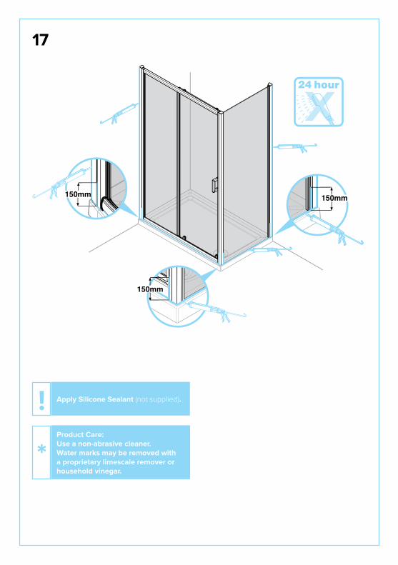
17
Apply Silicone Sealant (not supplied).!Product Care: Use a non-abrasive cleaner. Water marks may be removed with a proprietary limescale remover or household vinegar.
*

Notes:Notes:

Notes:Notes: