slide 1 software requirements. slide 2 objectives l to introduce the concepts of user and system...
Post on 19-Dec-2015
219 views
TRANSCRIPT

Slide 1
Software Requirements

Slide 2
Objectives
To introduce the concepts of user and system requirements
To describe functional and non-functional requirements
To explain the organization of the requirements document that you will be required to produce for your projects.

Slide 3
Requirements engineering
The process of establishing the services that the customer requires from a system and the constraints under which it operates and is developed.
The requirements themselves are the descriptions of the system services and constraints that are generated during the requirements engineering process.

Slide 4
What is a requirement?
It may range from a high-level abstract statement of a service or of a system constraint to a detailed mathematical functional specification.
This is inevitable as requirements may serve a dual function• May be the basis for a bid for a contract - therefore
must be open to interpretation;• May be the basis for the contract itself - therefore
must be defined in detail;• Both these statements may be called requirements.

Slide 5
Requirements abstraction
“If a company wishes to let a contract for a large software development project, itmust define its needs in a sufficiently abstract way that a solution is not pre-defined.The requirements must be written so that several contractors can bid for the contract,offering, perhaps, different ways of meeting the client organisation’s needs. Once acontract has been awarded, the contractor must write a system definition for the clientin more detail so that the client understands and can validate what the software willdo. Both of these documents may be called the requirements document for thesystem.”

Slide 6
Types of requirement
User requirements• Statements in natural language plus diagrams of the
services the system provides and its operational constraints. Written primarily for customers.
System requirements• A structured document setting out detailed
descriptions of the system’s functions, services and operational constraints. Defines what should be implemented so may be part of a contract between client and contractor.

Slide 7
User Requirement - Example
The software must provide a means of representing and accessing external files created by other tools.

Slide 8
System Requirements – Example (A)
The external file type shall have an associated tool which shall be applied to the file.
Each external file type shall be represented as a specific icon on the user’s display.

Slide 9
System Requirements – Example (B)
Facilities shall be provided for the icon representing an external file type to be defined by the user.
The user shall be provided with facilities to define the type of external files.
When a user selects an icon representing an external file, the effect of that selection shall be to apply the tool associated with the type of the external file to the file represented by the selected icon.
Slide 10
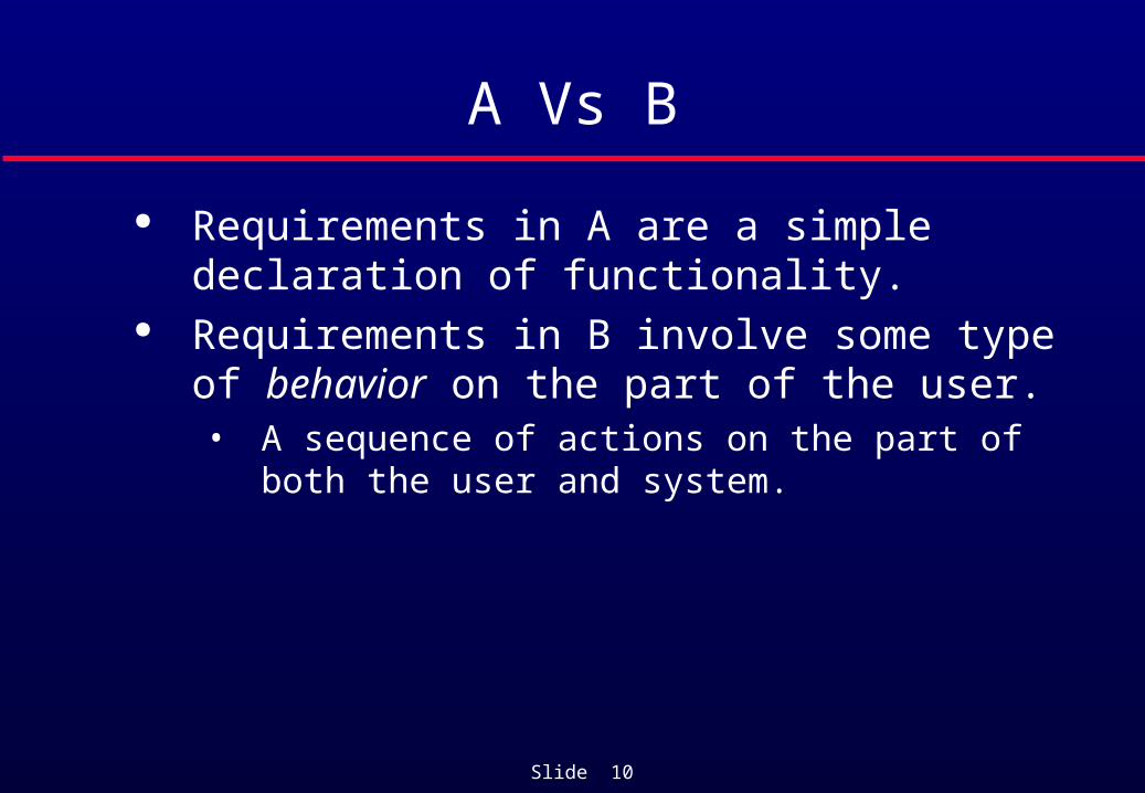
A Vs B
Requirements in A are a simple declaration of functionality.
Requirements in B involve some type of behavior on the part of the user.• A sequence of actions on the part of both the user
and system.

Slide 11
Requirements readers
Client managersSystem end-usersClient engineersContractor managersSystem architects
System end-usersClient engineersSystem architectsSoftware developers
Client engineers (perhaps)System architectsSoftware developers
Userrequirements
Systemrequirements
Software designspecification

Slide 12
Functional and non-functional requirements
Functional requirements• Statements of services the system should provide, how the
system should react to particular inputs and how the system should behave in particular situations.
Non-functional requirements• constraints on the services or functions offered by the system
such as timing constraints, constraints on the development process, standards, etc.
Domain requirements• Requirements that come from the application domain of the
system and that reflect characteristics of that domain.

Slide 13
Functional requirements
Describe functionality or system services. Depend on the type of software, expected users
and the type of system where the software is used.
Functional user requirements may be high-level statements of what the system should do but functional system requirements should describe the system services in detail.

Slide 14
The LIBSYS system
A library system that provides a single interface to a number of databases of articles in different libraries.
Users can search for, download and print these articles for personal study.

Slide 15
Examples of functional user requirements
The user shall be able to search either all of the initial set of databases or select a subset from it.
The system shall provide appropriate viewers for the user to read documents in the document store.
Every order shall be allocated a unique identifier (ORDER_ID) which the user shall be able to copy to the account’s permanent storage area.
Slide 16
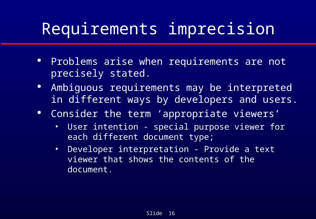
Requirements imprecision
Problems arise when requirements are not precisely stated.
Ambiguous requirements may be interpreted in different ways by developers and users.
Consider the term ‘appropriate viewers’• User intention - special purpose viewer for each
different document type;• Developer interpretation - Provide a text viewer that
shows the contents of the document.

Slide 17
Requirements completeness and consistency
In principle, requirements should be both complete and consistent.
Complete• They should include descriptions of all facilities
required. Consistent
• There should be no conflicts or contradictions in the descriptions of the system facilities.
In practice, it is impossible to produce a complete and consistent requirements document.

Slide 18
Non-functional requirements
These define system properties and constraints e.g. reliability, response time and storage requirements.
Process requirements may also be specified mandating a particular CASE system, programming language or development method.
Non-functional requirements may be more critical than functional requirements. If these are not met, the system is useless.

Slide 19
Non-functional requirement types
Product requirements• Requirements which specify that the delivered product must
behave in a particular way e.g. execution speed, reliability, etc. Organisational requirements
• Requirements which are a consequence of organisational policies and procedures e.g. process standards used, implementation requirements, etc.
External requirements• Requirements which arise from factors which are external to
the system and its development process e.g. interoperability requirements, legislative requirements, etc.

Slide 20
Non-functional requirement types
Performancerequirements
Spacerequirements
Usabilityrequirements
Efficiencyrequirements
Reliabilityrequirements
Portabilityrequirements
Interoperabilityrequirements
Ethicalrequirements
Legislativerequirements
Implementationrequirements
Standardsrequirements
Deliveryrequirements
Safetyrequirements
Privacyrequirements
Productrequirements
Organisationalrequirements
Externalrequirements
Non-functionalrequirements

Slide 21
Non-functional requirement examples Product requirement
8.1 The user interface for LIBSYS shall be implemented as simple HTML without frames or Java applets.
Organisational requirement9.3.2 The system development process and deliverable documents shall
conform to the process and deliverables defined in XYZCo-SP-STAN-95.
External requirement7.6.5 The system shall not disclose any personal information about
customers apart from their name and reference number to the operators of the system.

Slide 22
Goals and requirements
Non-functional requirements may be very difficult to state precisely and imprecise requirements may be difficult to verify.
Goal• A general intention of the user such as ease of use.
• Requirement that is very difficult to verify. Verifiable non-functional requirement
• A statement using some measure that can be objectively tested.
Goals are helpful to developers as they convey the intentions of the system users.• But be very careful with goals whose achievement can’t be
verified.
Slide 23
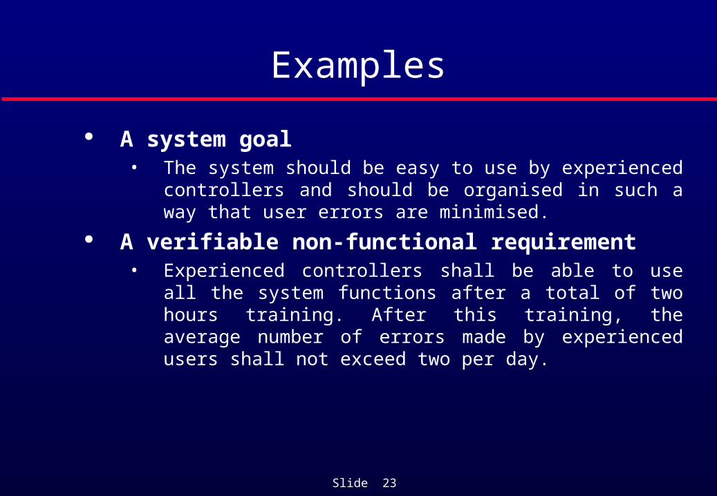
Examples
A system goal• The system should be easy to use by experienced controllers
and should be organised in such a way that user errors are minimised.
A verifiable non-functional requirement• Experienced controllers shall be able to use all the system
functions after a total of two hours training. After this training, the average number of errors made by experienced users shall not exceed two per day.
Slide 24
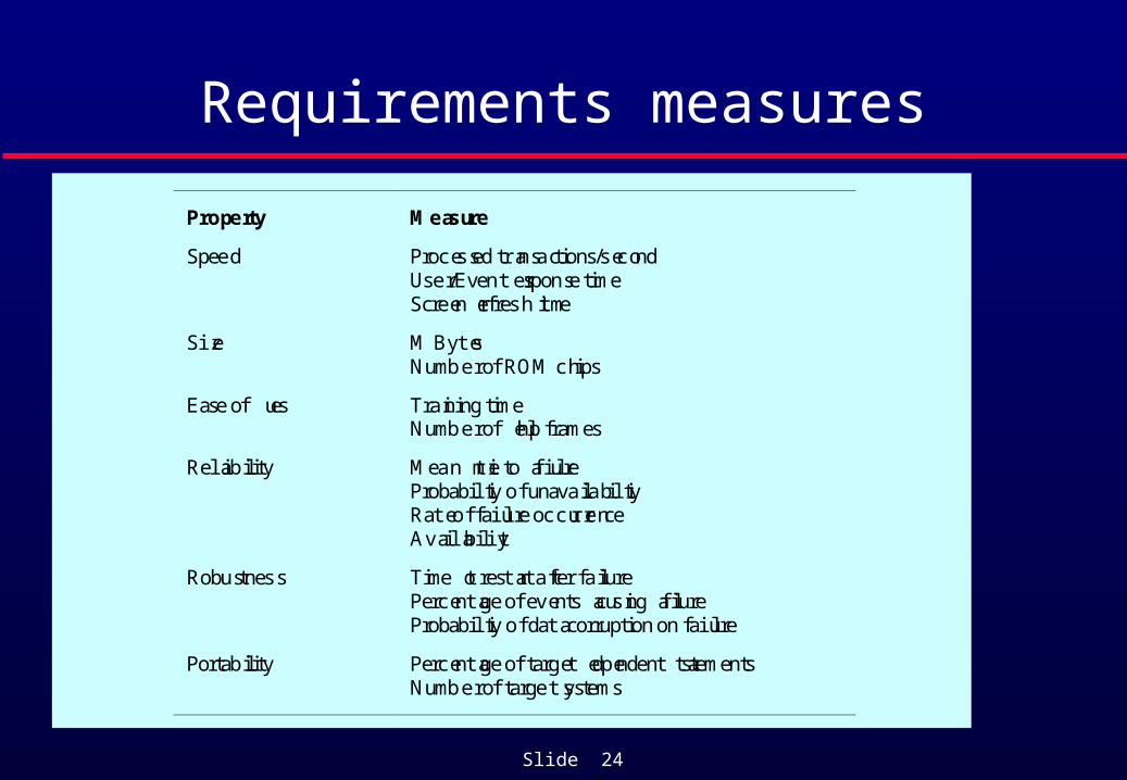
Requirements measures
Property Measure
Speed Processed transactions/secondUser/Event response timeScreen refresh time
Size M BytesNumber of ROM chips
Ease of use Training timeNumber of help frames
Reliability Mean time to failureProbability of unavailabilityRate of failure occurrenceAvailability
Robustness Time to restart after failurePercentage of events causing failureProbability of data corruption on failure
Portability Percentage of target dependent statementsNumber of target systems
Slide 25
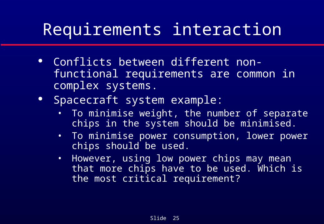
Requirements interaction
Conflicts between different non-functional requirements are common in complex systems.
Spacecraft system example:• To minimise weight, the number of separate chips in
the system should be minimised.• To minimise power consumption, lower power chips
should be used.• However, using low power chips may mean that
more chips have to be used. Which is the most critical requirement?

Slide 26
Domain requirements
Derived from the application domain and describe system characteristics and features that reflect the domain.
Domain requirements become new functional requirements, constraints on existing requirements or define specific computations.
If domain requirements are not satisfied, the system may be unworkable.

Slide 27
Library system domain requirements
There shall be a standard user interface to all databases which shall be based on the Z39.50 standard.
Because of copyright restrictions, some documents must be deleted immediately on arrival. Depending on the user’s requirements, these documents will either be printed locally on the system server for manually forwarding to the user or routed to a network printer.

Slide 28
Train protection system
The deceleration of the train shall be computed as:
• Dtrain = Dcontrol + Dgradient
where Dgradient is 9.81ms2 * compensated gradient/alpha and where the values of 9.81ms2 /alpha are known for different types of train.

Slide 29
Domain requirements problems
Understandability• Requirements are expressed in the language of the
application domain;• This is often not understood by software engineers
developing the system. Implicitness
• Domain specialists understand the area so well that they do not think of making the domain requirements explicit.

Slide 30
User requirements
Should describe functional and non-functional requirements in such a way that they are understandable by system users who don’t have detailed technical knowledge.
User requirements are defined using natural language, tables and diagrams as these can be understood by all users.

Slide 31
Problems with natural language
Lack of clarity • Precision is difficult without making the document
difficult to read. Requirements confusion
• Functional and non-functional requirements tend to be mixed-up.
Requirements amalgamation• Several different requirements may be expressed
together.

Slide 32
LIBSYS requirement
4..5 LIBSYS shall provide a financial accounting system that maintains records of all payments made by users of the system. System managers may configure this system so that regular users may receive discounted rates.

Slide 33
LIBSYS Requirement Problem
Includes both conceptual and detailed information• Describes the concept of a financial accounting
system that is to be included in LIBSYS;• However, it also includes the detail that managers
can configure this system - this is unnecessary at this level.

Slide 34
Editor grid requirement
2.6 Grid facilities To assist in the positioning of entities on a diagram, the user may turn on a grid in either centimetres or inches, via an option on the control panel. Initially, the grid is off. The grid may be turned on and off at any time during an editing session and can be toggled between inches and centimeters at any time. A grid option will be provided on the reduce-to-fit view but the number of grid lines shown will be reduced to avoid filling the smaller diagram with grid lines.

Slide 35
Editor Grid Requirement Problem
Mixes three different kinds of requirement• Conceptual functional requirement (the need for a
grid);• Non-functional requirement (grid units);• Non-functional UI requirement (grid switching).

Slide 36
Structured presentation – Conceptual Functional Requirement Only
2.6.1 Grid facilitiesThe editor shall provide a grid facility where a m atrix of horizontal andvertical lines provide a background to the editor window. This grid shall be apassive grid where the alignment of entities is the user's responsibility.
Rationale: A grid helps the user to create a tidy diagram with well-spacedentities. Although an active grid, where entities 'snap-to' grid lines can be useful,the positioning is imprecise. The user is the best person to decide where entitiesshould be positioned.
Specification: ECLIPSE/WS/Tools/DE/FS Section 5.6Source: Ray Wilson, Glasgow Office

Slide 37
Guidelines for writing requirements
Invent a standard format and use it for all requirements.
Use language in a consistent way. Use shall for mandatory requirements, should for desirable requirements.
Use text highlighting to identify key parts of the requirement.
Avoid the use of computer jargon.
Slide 38
System requirements
More detailed specifications of system functions, services and constraints than user requirements.
They are intended to be a basis for designing the system.
They may be incorporated into the system contract.

Slide 39
Requirements Vs Design
In principle, requirements should state what the system should do and the design should describe how it does this.
In practice, requirements and design are sometimes inseparable• A system architecture may be designed to structure
the requirements;• The system may inter-operate with other systems that
generate design requirements;• The use of a specific design may be a domain
requirement.
Slide 40
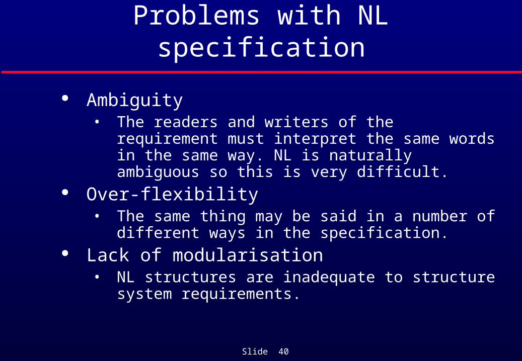
Problems with NL specification
Ambiguity• The readers and writers of the requirement must
interpret the same words in the same way. NL is naturally ambiguous so this is very difficult.
Over-flexibility• The same thing may be said in a number of different
ways in the specification. Lack of modularisation
• NL structures are inadequate to structure system requirements.

Slide 41
Alternatives to NL specification
Notation Description
Structured naturallanguage
This approach depends on defining standard forms or templates to express therequirements specification.
Designdescriptionlanguages
This approach uses a language like a programming language but with more abstractfeatures to specify the requirements by defining an operational model of the system.This approach is not now widely used although it can be useful for interfacespecifications.
Graphicalnotations
A graphical language, supplemented by text annotations is used to define thefunctional requirements for the system. An early example of such a graphicallanguage was SADT. Now, use-case descriptions and sequence diagrams arecommonly used .
Mathematicalspecifications
These are notations based on mathematical concepts such as finite-state machines orsets. These unambiguous specifications reduce the arguments between customer andcontractor about system functionality. However, most customers don’t understandformal specifications and are reluctant to accept it as a system contract.

Slide 42
Structured language specifications
The freedom of the requirements writer is limited by a predefined template for requirements.
All requirements are written in a standard way. The terminology used in the description may be
limited. The advantage is that the most of the
expressiveness of natural language is maintained but a degree of uniformity is imposed on the specification.
Slide 43
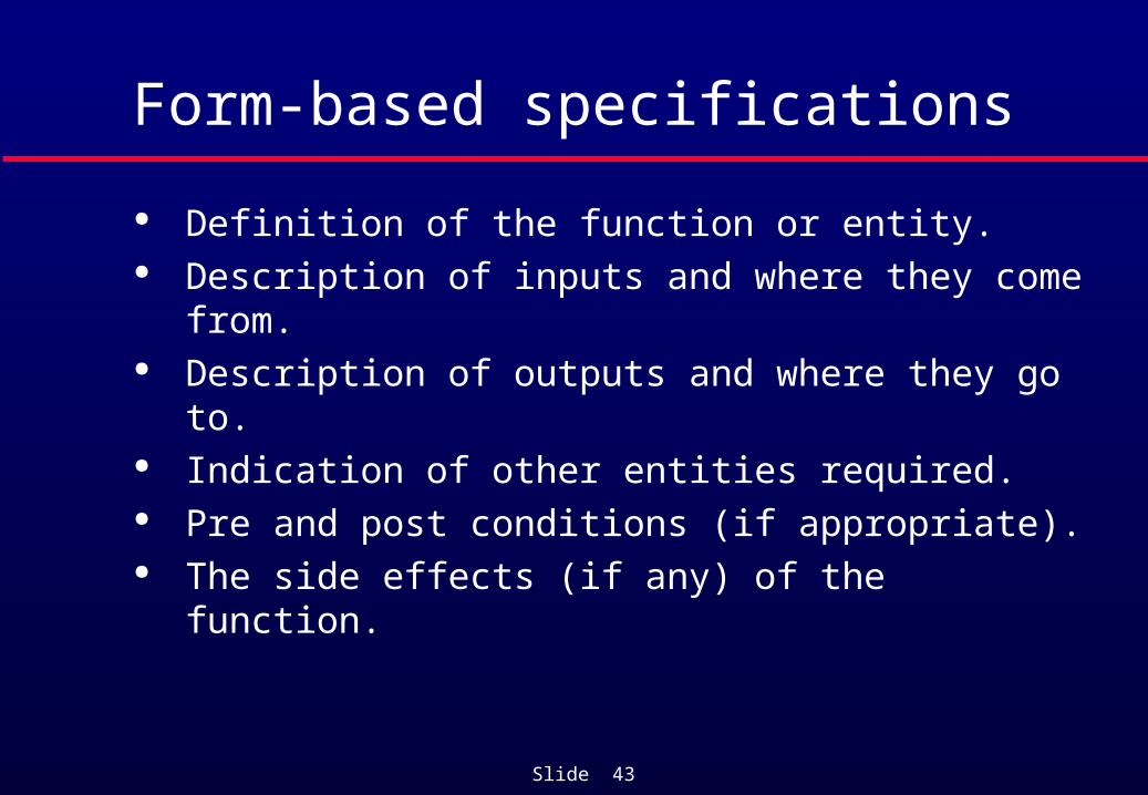
Form-based specifications
Definition of the function or entity. Description of inputs and where they come from. Description of outputs and where they go to. Indication of other entities required. Pre and post conditions (if appropriate). The side effects (if any) of the function.
Slide 44
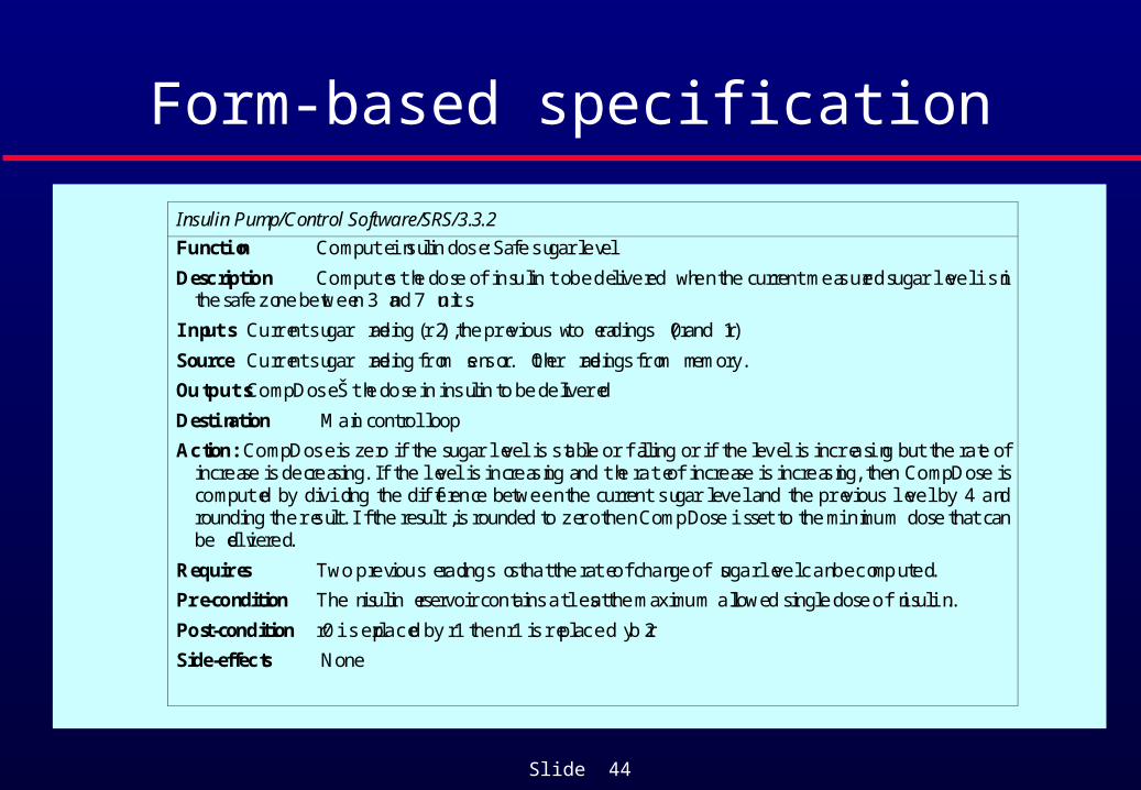
Form-based specification
Insulin Pump/Control Software/SRS/3.3.2
Function Compute insulin dose: Safe sugar level
Description Computes the dose of insulin to be delivered when the current measured sugar level is inthe safe zone between 3 and 7 units.
Inputs Current sugar reading (r2), the previous two readings (r0 and r1)
Source Current sugar reading from sensor. Other readings from memory.
Outputs CompDose Š the dose in insulin to be delivered
Destination Main control loop
Action: CompDose is zero if the sugar level is stable or falling or if the level is increasing but the rate ofincrease is decreasing. If the level is increasing and the rate of increase is increasing, then CompDose iscomputed by dividing the difference between the current sugar level and the previous level by 4 androunding the result. If the result, is rounded to zero then CompDose is set to the minimum dose that canbe delivered.
Requires Two previous readings so that the rate of change of sugar level can be computed.
Pre-condition The insulin reservoir contains at least the maximum allowed single dose of insulin..
Post-condition r0 is replaced by r1 then r1 is replaced by r2
Side-effects None
Slide 45
Tabular specification
Used to supplement natural language. Particularly useful when you have to define a
number of possible alternative courses of action.

Slide 46
Tabular specification
Condition Action
Sugar level falling (r2 < r1) CompDose = 0
Sugar level stable (r2 = r1) CompDose = 0
Sugar level increasing and rate ofincrease decreasing ((r2-r1)<(r1-r0))
CompDose = 0
Sugar level increasing and rate ofincrease stable or increasing. ((r2-r1) (r1-r0))
CompDose = round ((r2-r1)/4)If rounded result = 0 thenCompDose = MinimumDose

Slide 47
Use Cases
Represents a contract between the stakeholders of a system about its behavior.
Describes the system’s behavior under various conditions as the system responds to a request from one of the stakeholders – the primary actor for that use case.
Primary actor initiates an interaction with the system to accomplish some goal.
System responds.

Slide 48
Use Cases
Different sequences of behavior (scenarios) can unfold depending on the particular requests made and the conditions surrounding the requests.
The use case gathers the different scenarios together.
A well-written use case is easy to read. Learning to write a good use case is hard.
Slide 49
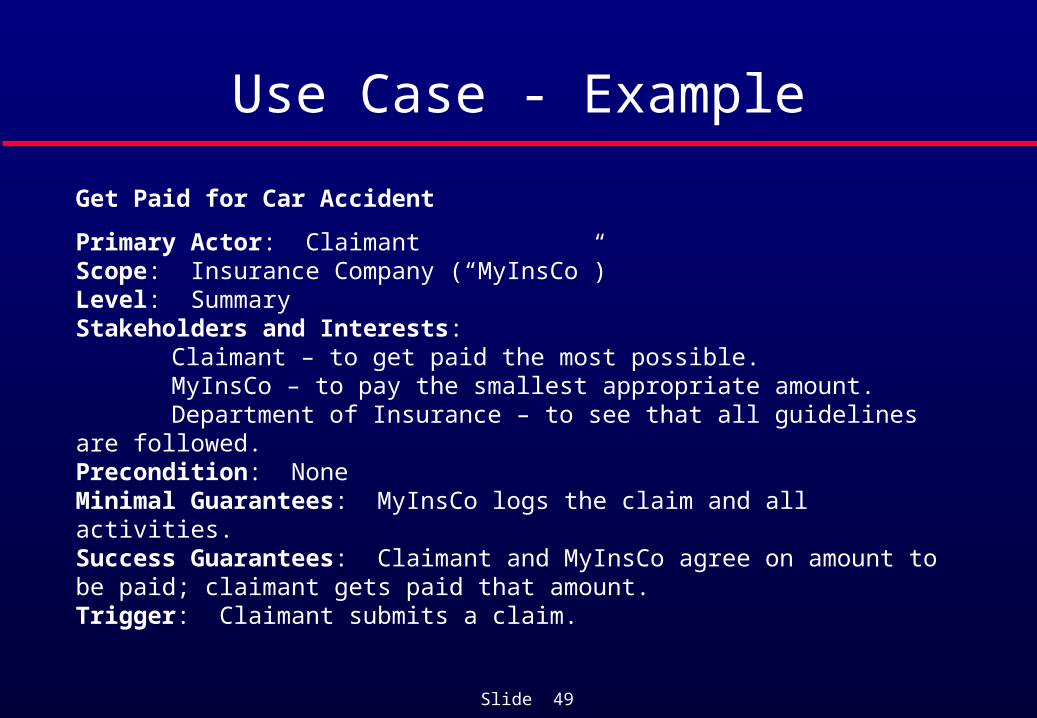
Use Case - Example
Get Paid for Car Accident
Primary Actor: ClaimantScope: Insurance Company (“MyInsCo”)Level: SummaryStakeholders and Interests:
Claimant – to get paid the most possible.MyInsCo – to pay the smallest appropriate amount.Department of Insurance – to see that all guidelines are followed.
Precondition: NoneMinimal Guarantees: MyInsCo logs the claim and all activities.Success Guarantees: Claimant and MyInsCo agree on amount to be paid; claimant gets paid that amount.Trigger: Claimant submits a claim.

Slide 50
Use Case – Example (cont)
Main Success Scenario:1. Claimant submits claim with substantiating data.2. Insurance company verifies claimant owns a valid policy.3. Insurance company assigns agent to examine case.4. Insurance company verifies all details are within policy guidelines.5. Insurance company pays claimant and closes file.Extensions:1a. Submitted data is incomplete:
1a1. Insurance company requests missing information.1a2. Claimant supplies missing information.
2a. Claimant does not own a valid policy:2a1. Insurance company denies claim, notifies claimant, records all this, terminates proceedings.

Slide 51
Use Case – Example (cont)
3a. No agents are available at this time.3a1. (What does the insurance company do here?)
4a. Accident violates basic policy guidelines:4a1. Insurance company denies claim, notifies claimant, records all this, terminates proceedings.
4b. Accident violates some minor policy guidelines:4b1. Insurance company begins negotiation with claimant as to amount of payment to be made.
Slide 52
Graphical models
Graphical models are most useful when you need to show how state changes or where you need to describe a sequence of actions.

Slide 53
Sequence diagrams
These show the sequence of events that take place during some user interaction with a system.
You read them from top to bottom to see the order of the actions that take place.
Example: Cash withdrawal from an ATM• Validate card;• Handle request;• Complete transaction.

Slide 54
Sequence diagram of ATM withdrawalATM Database
CardCard number
Card OKPIN request
PIN
Option menu
<<exception>>invalid card
Withdraw request
Amount request
Amount
Balance request
Balance
<<exception>>insufficient cash
Debit (amount)
Debit response
Card
Card removed
Cash
Cash removed
Receipt
Validate card
Handle request
Completetransaction

Slide 55
Interface specification
Most systems must operate with other systems and the operating interfaces must be specified as part of the requirements.
Three types of interface may have to be defined• Procedural interfaces;• Data structures that are exchanged;• Data representations.
Formal notations are an effective technique for interface specification.

Slide 56
Procedural Interface description in Java
interface PrintServer {
// defines an abstract printer server// requires: interface Printer, interface PrintDoc// provides: initialize, print, displayPrintQueue, cancelPrintJob, switchPrinter
void initialize ( Printer p ) ;void print ( Printer p, PrintDoc d ) ;void displayPrintQueue ( Printer p ) ;void cancelPrintJob (Printer p, PrintDoc d) ;void switchPrinter (Printer p1, Printer p2, PrintDoc d) ;
} //PrintServer
Slide 57
The requirements document
The requirements document is the official statement of what is required of the system developers.
Should include both a definition of user requirements and a specification of the system requirements.
It is NOT a design document. As far as possible, it should say WHAT the system should do rather than HOW it should do it

Slide 58
Users of a requirements document
Use the requirements todevelop validation tests for
the system
Use the requirementsdocument to plan a bid forthe system and to plan the
system development process
Use the requirements tounderstand what system is to
be developed
System testengineers
Managers
Systemengineers
Specify the requirements andread them to check that they
meet their needs. Theyspecify changes to the
requirements
Systemcustomers
Use the requirements to helpunderstand the system and
the relationships between itsparts
Systemmaintenanceengineers

Slide 59
Requirements document structure
Preface Introduction Glossary User requirements definition System architecture System requirements specification System evolution Appendices Index

Slide 60
Preface
Define the expected readership of the document. Describe version history.
• Rational for the creation of each new version.• A summary of the changes made in each version.

Slide 61
Introduction
Describe the need for the system. Briefly describe its functions and how it will work
with other systems. Describe how the system fits in with the business
or strategic objectives of the commisioning organization.

Slide 62
Glossary
Define the technical terms used in the document. Do not make assumptions about the experience
or expertise of the reader.

Slide 63
User Requirements Definition
Describe the services provided for the user, i.e., the functional requirements.
Describe the non-functional requirements. Descriptions may use NL, diagrams, or other
notations understandable by the customer. Behavioral descriptions must be specified using
use cases. Specify any product or process standards that
must be followed.

Slide 64
System Architecture
Present a high level overview of the anticipated system architecture.
Show the distribution of functions across system modules.
Highlight architectural components that are reused.

Slide 65
System Requirements Specification
Describe the functional and non-functional requirements in more detail than the User Requirements Definition section.
Behavioral descriptions must be specified with use cases. Show the trace back to the user requirements from each
of the system requirements. Add any additional necessary details to the non-
functional requirements• E.g., interfaces to other systems might be defined.
Slide 66
System Evolution
Describe the fundamental assumptions on which the system is based.
Specify anticipated changes due to • Hardware evolution• Changing user needs• Etc.

Slide 67
Appendices
Provide detailed, specific information which is related to the application which is being developed.
Examples • Hardware descriptions
• Minimal and optimal configurations for the system.
• Data base descriptions• Logical organization of the data• Relationships between the data

Slide 68
Index
Several indexes may be included• Normal alphabetic index• Index of diagrams• Index of functions• Etc.
Slide 69
Key points
Requirements set out what the system should do and define constraints on its operation and implementation.
Functional requirements set out services the system should provide.
Non-functional requirements constrain the system being developed or the development process.
User requirements are high-level statements of what the system should do. User requirements should be written using natural language, use cases, tables and diagrams.

Slide 70
Key points
System requirements are intended to communicate the functions that the system should provide.
A software requirements document is an agreed statement of the system requirements.