sled test evaluation - umich.edu
TRANSCRIPT
SLED TEST EVALUATION
OF A
WHEELCHAIR RESTRAINT SYSTEM
FOR USE BY HANDICAPPED DRIVERS
Lawrence W. Sc hne i d e r
and
John W. M e l v i n
A s p e c i a l r e p o r t p repared f o r
The U n i v e r s i t y of M ich igan Rehabi 1 i t a t i o n Eng ineer ing Center
November, 1 978
A
, 3. U w r o a t ' r Cardoq No.
5. R- 0410
November 21, 1978 ' 6. pr(wrmq O , ~ ~ O ~ , GC
HSRI 8. Pr(.rru. Ot-am~~aa RIPI( k.
UM-HSRI-78-57
10. W d k t No. (TRAIS)
11. 6 n w o c t o r C l a t N a
1. R- I(c
UM-HSRI-78-57 2 A a m s u a k
& fill0 4 u h t h
Sled Tes t Eva lua t ion o f a Wheelchair R e s t r a i n t System For Use By Handicapped D r i v e r s
7. -3 Lawrence W . Schneider and John W. Me l v i n
9. P u b u w q 0rqmtuci.r U r n ad Addtor.
Highway Sa fe t y Research I n s t i t u t e The U n i v e r s i t y of Mich igan Ann Arbor, Mich igan 48109
' ~ ~ o ~ u ~ ~ TeZ?'rpmen t Rehabi 1 i t a t i o n Serv ices Admini s t r a t i o n Department of Heal t h , Educat ion and We1 f a r e Washington, D.C.
17. T l r o i R . r r c d ~ ~ d & . ~ d
Specia l June, 1978-October, 1978
14. 3 ~ . r n m ~ ~ A-V ~ d .
15. s , , , ~ t ~ no-s
Th i s work was conducted f o r t h e U n i v e r s i t y o f Mich igan Rehabil i t a t i o n Engineer ing Center ._
Tb. Aha-
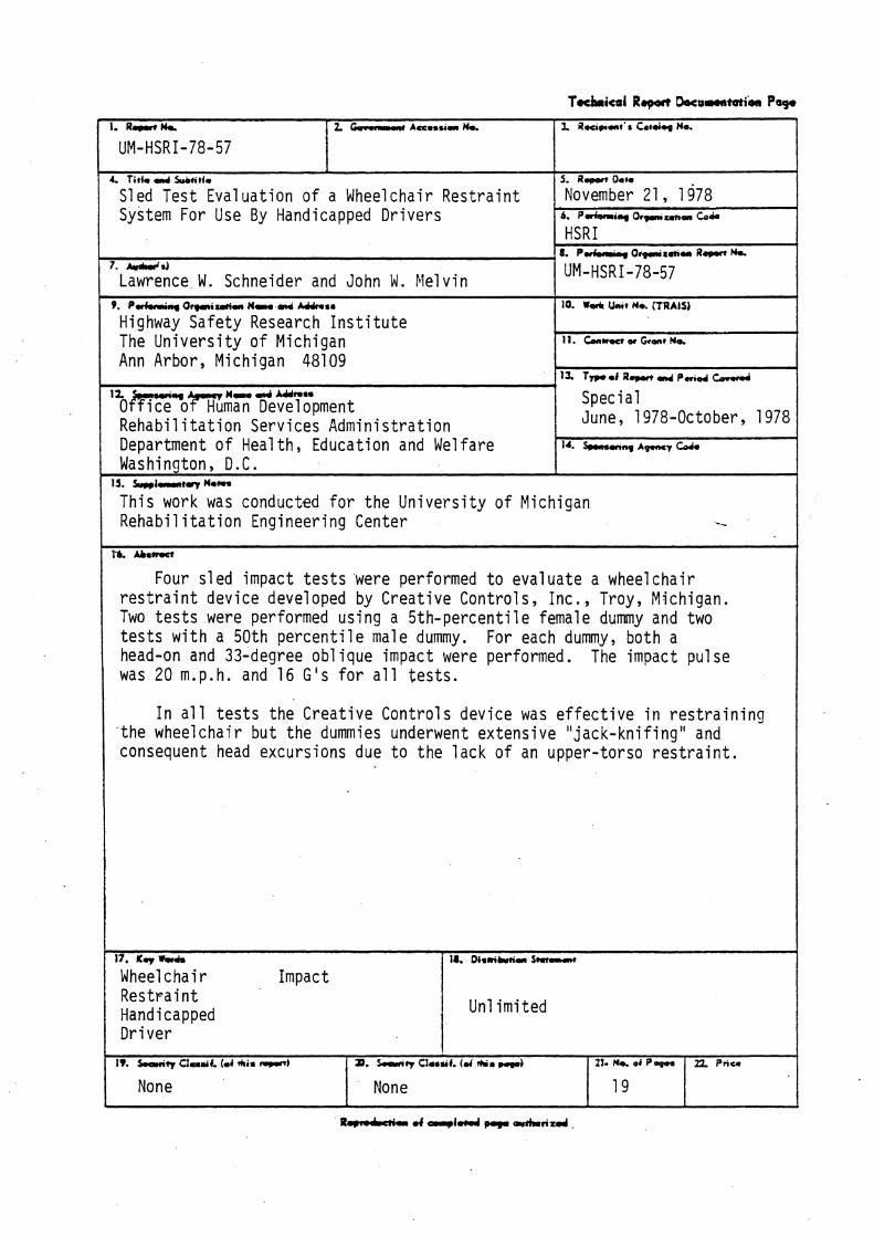
Four s l e d impact t e s t s were performed t o eva lua te a wheelchai r r e s t r a i n t dev i ce developed by C rea t i ve Con t ro l s , Inc . , Troy, Michigan. Two t e s t s were performed us i ng a 5 t h - p e r c e n t i l e female dummy and two t e s t s w i t h a 50th p e r c e n t i l e male dummy. For each dummy, bo th a head-on and 33-degree o b l i q u e impact were performed. The impact pu lse was 20 m.p.h. and 16 G 's f o r a l l t e s t s .
I n a l l t e s t s t h e C r e a t i v e Con t ro l s dev ice was e f f e c t i v e i n r e s t r a i n i n g t h e wheel c h a i r b u t t h e dummies underwent ex tens ive " j a c k - k n i f i n g " and consequent head excurs ions due t o t h e l a c k of an upper - to rso r e s t r a i n t .
17. I[.* M.
Wheel c h a i r Impact R e s t r a i n t Handicapped D r i v e r
1J. Dism&km S-
Unl i m i t e d
19. h q Cludf . (m4 rkls -1
None
R d a of - 4 4 a u k r i x s d
2 2 P n u 3. Smlv Cfasuf. (d th. mi
None
21. of P v
19
CONTENTS
Page L i s t of Tab les ...................................... i
D e s c r i p t i o n of C r e a t i v e Con t ro l s Device ------------- 4
Appendix - Photographs of Tes t R e s u l t s -------------- 10
Table No.
LIST OF TABLES
T i t l e Page
M a t r i x o f Tests 4
Approximate Head and Knee Excursions 7 i n D i r e c t i o n of Impact R e l a t i v e t o Wheel c h a i r Frame
LIST OF FIGURES
Figure No. Caption Page
1 HSRI ' s Impact Sl ed Faci 1 i ty 2
2 Sled Test Decel eration Pul se 3
3 Creative Controls Wheelchair Restraint 5 Device Mounted to Sled Rails
4 Rearview of Creative Control s Device 6 Showing Front and Rear Bars and Grips

INTRODUCTION AND OBJECTIVE
Prov id i ng f o r m o b i l i t y o f handicapped a d u l t s r e q u i r e s n o t o n l y
development of equipment and dev ices which w i l l a1 low independent
ope ra t i on of p r i v a t e v e h i c l es , bu t development of adequate r e s t r a i n t
systems t o p r o t e c t these handicapped d r i v e r s and occupants i n v e h i c l e
c o l l i s i o n s . U n t i l r e c e n t l y , 1 i t t l e concern and e f f o r t has been devoted
t o t h e l a t t e r area. As a r e s u l t , handicapped i n d i v i d u a l s f o r t u n a t e
enough t o have found a means f o r ope ra t i ng a v e h i c l e are, i n most
cases, comp le te ly unpro tec ted i n t h e event of a crash.
Whi le des ign ing f o r impact p r o t e c t i o n of normal v e h i c l e occupants
i s a complex and d i f f i c u l t eng ineer ing problem, des ign ing f o r the -g ro -
t e c t i o n of handicapped i n d i v i d u a l s , w i t h t h e i r spec ia l equipment and
a s s i s t i n g dev ices as w e l l as s t r e n g t h and m o b i l i t y l i m i t a t i o n s , p re -
sents a d d i t i o n a l problems i n crashwor th iness design. For example,
one cannot assume t h a t a wheelchai r occupant can fas ten a standard
shoulder harness o r t h a t t h e wheelchai r s t r u c t u r e can be used w i t h o u t
m o d i f i c a t i o n t o c a r r y t h e loads due t o impact.
As awareness of t he need t o p r o t e c t as w e l l as m o b i l i z e t h e handi -
capped person increases, new dev ices and equipment w i l l be developed
and marketed. An impo r tan t aspect of t h e e v a l u a t i o n o f these dev ices
p r i o r t o i n s t a l l a t i o n and use must i n c l u d e dynamic t e s t i n g under r e a l -
i s t i c and app rop r i a t e cond i t i ons .
The purpose of t h i s s tudy was t o conduct a s e r i e s of impact t e s t s
t o eva lua te t h e performance of a wheelchai r r e s t r a i n t dev ice developed
by C r e a t i v e Con t ro ls , Inc . , f o r use by handicapped d r i v e r s .
PROCEDURES
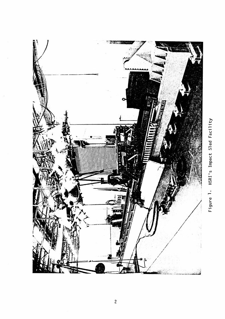
Impact t e s t i n g of t he C rea t i ve Con t ro l s wheelcha i r r e s t r a i n t was
performed a t t h e Highway Safety Research I n s t i t u t e ' s Impact Sled Labor-
a t o r y . Th i s f a c i l i t y c o n s i s t s of an impact s l ed (F i gu re 1 ) t h a t moves
on a 45 - f oo t t r a c k i n t o a pneumatic dece le ra to r and can s imu la te crashes
up t o 75 m.p. h. and 75 t imes t h e fo rce o f g r a v i t y . The s l ed i t s e l f i s
a 975-1b t e s t p la t form, 6 .5 - f t square, d r i v e n by a compressed-
gas-powered ram. The s l e d operates on t h e p r i n c i p l e o f rebound, s topp ing
and r e v e r s i n g d i r e c t i o n a b r u p t l y by impact ing t h e a d j u s t a b l e pneumatic
dece le ra to r .
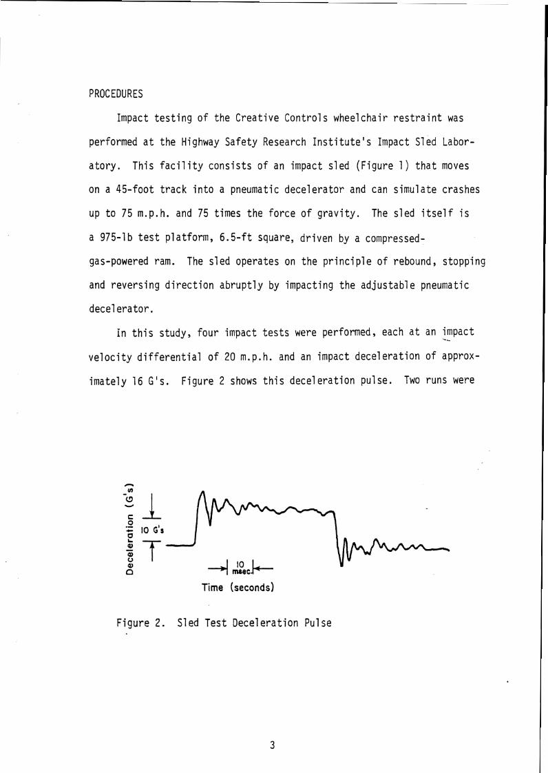
i n t h i s study, f o u r impact t e s t s were performed, each a t an -- impact
v e l o c i t y d i f f e r e n t i a l o f 20 m.p. h. and an impact d e c e l e r a t i o n of approx-
i m a t e l y 16 G 's . F i gu re 2 shows t h i s d e c e l e r a t i o n pu lse . Two runs were
Time (seconds)
F i g u r e 2. S led T e s t D e c e l e r a t i o n Pu lse
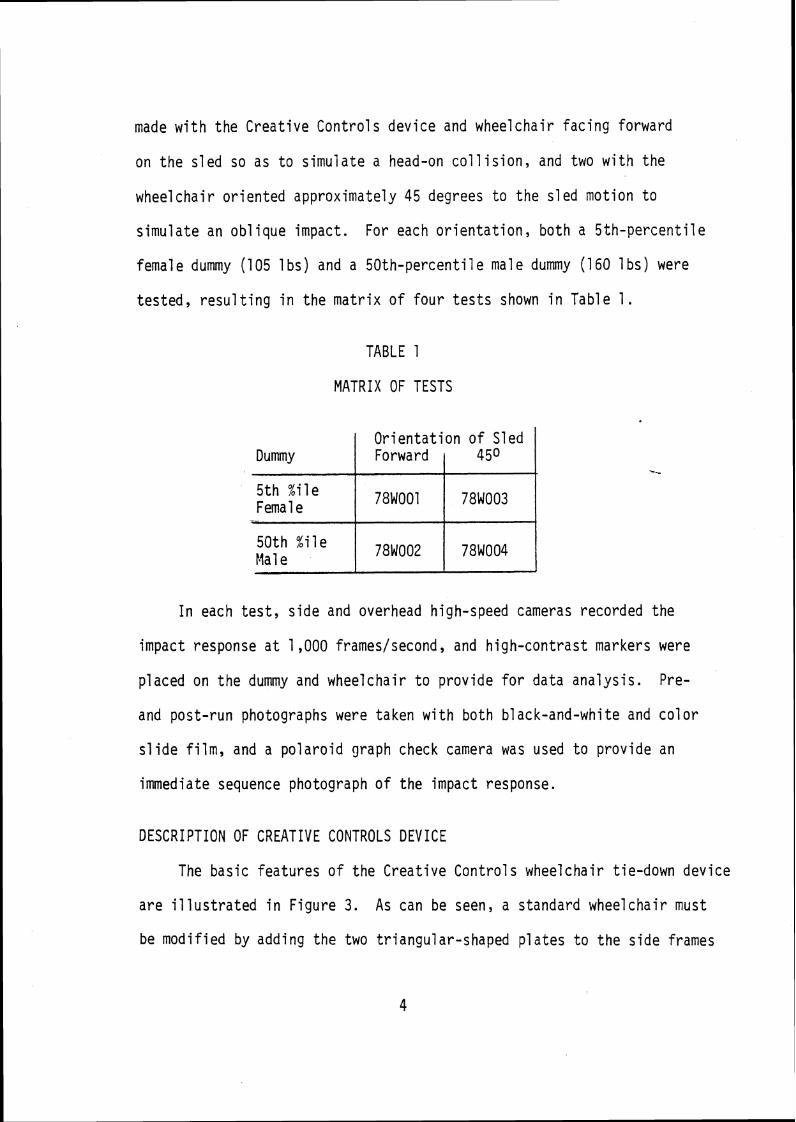
made w i t h t h e C rea t i ve Con t ro l s dev i ce and wheel c h a i r fac ing forward
on t h e s l e d so as t o s imu la te a head-on c o l l i s i o n , and two w i t h t h e
wheel c h a i r o r i e n t e d approx imate ly 45 degrees t o t h e s l ed mot ion t o
s imu la te an o b l i q u e impact. For each o r i e n t a t i o n , bo th a 5 t h - p e r c e n t i l e
female dummy (105 1 bs) and a 5 0 t h - p e r c e n t i l e male dummy (160 1 bs) were
t es ted , r e s u l t i n g i n t h e m a t r i x o f f o u r t e s t s shown i n Table 1.
TABLE 1
MATRIX OF TESTS
I n each t e s t , s i d e and overhead high-speed cameras recorded t h e
impact response a t 1,000 frameslsecond, and h i gh -con t ras t markers were
p laced on t h e dummy and wheelchai r t o p rov i de f o r da ta ana l ys i s . Pre-
and pos t - run photographs were taken w i t h bo th b lack-and-whi te and c o l o r
s l i d e f i l m , and a p o l a r o i d graph check camera was used t o p rov i de an
immediate sequence photograph of t he impact response.
Dummy
5 t h % i l e Fema 1 e
50 th % i l e Ma1 e
DESCRIPTION OF CREATIVE CONTROLS DEVICE
The bas ic f ea tu res o f t h e C rea t i ve Con t ro l s wheelcha i r t ie-down dev ice
a r e i l l u s t r a t e d i n F i gu re 3. As can be seen, a standard wheelchai r must
be modi f ied by adding t h e two t r iangu la r -shaped p l a t e s t o t h e s i d e frames
O r i e n t a t i o n o f S led Forward
78W001
781002
450
78W003
78W004
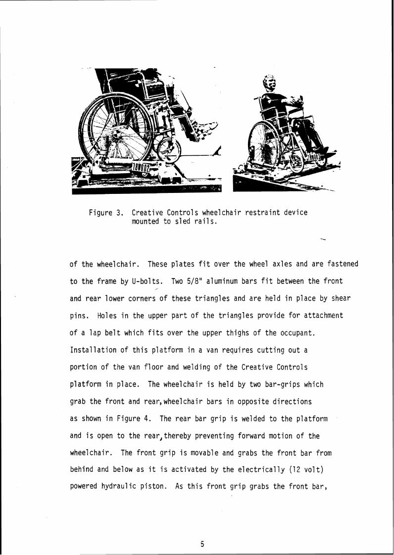
Figure 3. Creative Controls wheelchair restraint device mounted to s1 ed rai 1 s .
of the wheelchair. These plates f i t over the wheel axles and are fastened
t o the frame by U-bolts. Two 518" aluminum bars f i t between the front ,
and rear lower corners of these triangles and are held in place by shear
pins. Holes in the upper part of the triangles provide for attachment
o f a lap belt which f i t s over the upper thighs of the occupant.
Installation of this platform i n a van requires cutting ou t a
portion of the van floor and welding o f the Creative Controls
platform in place. The wheelchair i s held by two bar-grips which
grab the front and rear,wheelchair bars in opposite directions
as shown i n Figure 4. The rear bar grip i s welded t o the platform
and i s open t o the rear,thereby preventing forward motion of the
wheelchair. The front grip i s movable and grabs the front bar from
behind and below as i t i s activated by the electrically ( 1 2 v o l t )
powered hydraulic piston. As this front grip grabs the front bar,
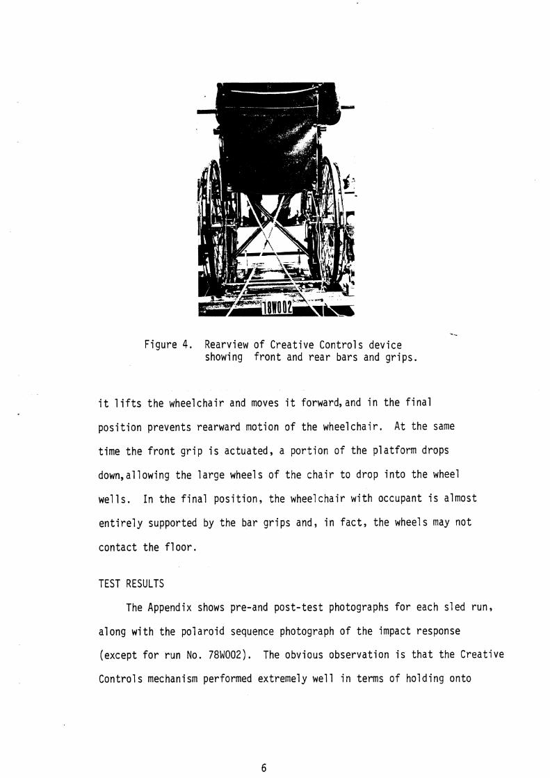
.- Figu re 4. Rearview of C rea t i ve Con t ro ls dev ice
showing f r o n t and r e a r bars and g r i p s .
i t 1 i f t s t h e wheelchai r and moves i t forward, and i n t h e f i n a l
p o s i t i o n p reven ts rearward mot ion o f t he whee lcha i r . A t t h e same
t ime t h e f r o n t g r i p i s actuated, a p o r t i o n o f t h e p l a t f o r m drops
down,allowing t h e l a r g e wheels o f t h e c h a i r t o d rop i n t o t h e wheel
w e l l s . I n t h e f i n a l p o s i t i o n , t h e wheelchai r w i t h occupant i s almost
e n t i r e l y supported by t h e bar g r i p s and, i n f a c t , t he wheels may n o t
c o n t a c t t h e f l o o r .
TEST RESULTS
The Appendix shows pre-and p o s t - t e s t photographs f o r each s l ed run,
a long w i t h t h e p o l a r o i d sequence photograph o f t h e impact response
(except f o r r u n No. 78W002). The obvious observa t ion i s t h a t t he C rea t i ve
Con t ro l s mechanism performed ext remely w e l l i n terms o f ho ld i ng on to
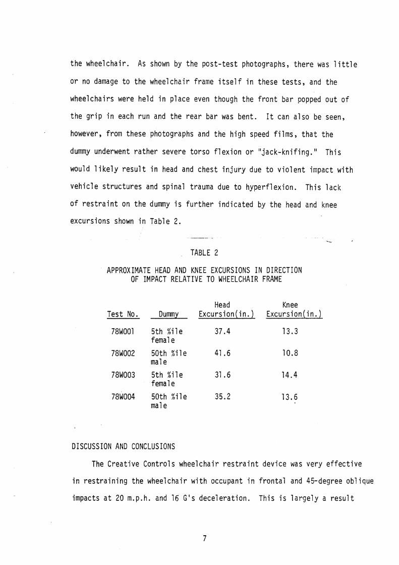
t h e wheelchai r . As shown by t h e p o s t - t e s t photographs, t h e r e was l i t t l e
o r no damage t o t h e wheelchai r frame i t s e l f i n these t e s t s , and t h e
wheelchai rs were he ld i n p l ace even though t he f r o n t bar popped o u t o f
t h e g r i p i n each r u n and t h e r e a r bar was bent . It can a l s o be seen,
however, from these photographs and t h e h i g h speed f i lms , t h a t t h e
dummy underwent r a t h e r severe t o r s o f l e x i o n o r " j a c k - k n i f i n g . " Th i s
would l i k e l y r e s u l t i n head and ches t i n j u r y due t o v i o l e n t impact w i t h
v e h i c l e s t r u c t u r e s and sp ina l trauma due t o hype r f l ex i on . Th is l a c k
of r e s t r a i n t on t h e dummy i s f u r t h e r i n d i c a t e d by t h e head and knee
excurs ions shown i n Table 2.
.,
TABLE 2
APPROXIMATE HEAD AND KNEE EXCURSIONS IN DIRECTION OF IMPACT RELATIVE TO WHEELCHAIR FRAME
Head Knee Tes t No. Dummy Excu rs i on ( i n . ) Excu rs i on ( i n . )
781001 5 t h % i l e 37.4 f emal e
78W003 5 t h % i l e 31.6 14.4 femal e
DISCUSSION AND CONCLUSIONS
The C rea t i ve Con t ro l s wheel c h a i r r e s t r a i n t dev i ce was ve ry e f f e c t i v e
i n r e s t r a i n i n g t h e wheelchai r w i t h occupant i n f r o n t a l and 45-degree ob l i que
impacts a t 20 m.p. h. and 16 G's dece le ra t i on . Th is i s l a r g e l y a r e s u l t

of the fac t that the triangles and bars added t o the wheelchair structure
provide a path for transmitting the iner t ia l loads t o the platform with-
out relying on the wheelchair frame. The lap be1 t loads are transmitted
through the triangles t o the rear bar, which i s the primary energy-absorb-
ing structure in these t e s t s , as indicated by the bending which resul ts .
While some bending of the bar i s good, in that i t reduces the severity
of the iner t ia l forces t o the occupant, too much bending could allow the
rear bar t o pop o u t of the grip, in which case the wheelchair would be
to ta l ly unrestrained. In th i s regard, since the front bar did pop o u t ,
the wheelchair was essential l y unrestrained from moving bac kward-after
the in i t i a l impact. For the impact pulse of these experiments, th i s
did no t present a problem, b u t for real-world collisions where multiple
impacts are n o t uncommon, the resul ts could have been much worse.
A significant part of the relatively large knee excursions observed
i s due to the manner in which the lap be1 t f i t s around the dummy. Because
the attachment points for the belt on the triangles are forward of the
seat back, the lap belt f i t s across the upper thighs rather than on the
pelvic region. Placement of the be1 t anchor points further rearward
(with perhaps some modification to the triangles) would provide for more
effective lower-torso res t ra in t .
I t i s also clear from these t e s t s that a lap belt alone i s not
adequate. A shoulder harness or upper-torso restraint i s required t o
keep the wheelchair occupant from impacting with vehicle surfaces. This
res t ra in t must, of course, be designed so that the handicapped individ-
ual can p u t i t on and take i t o f f with relat ive ease or i t s installation
would be useless. For example, the belts of an inverted Y-yoke harness
anchored to the van ceiling could be provided with cl ips that easily
attach to the seat frame of the wheelchair and hook t o the steering wheel
when not in use. With some structural modifications t o the wheel-
chair frame i t i s a1 so conceivable that the upper torso res t ra in t
could be anchored t o the wheel chair i t s e l f .
APPENDIX
PHOTOGRAPHS OF TEST RESULTS
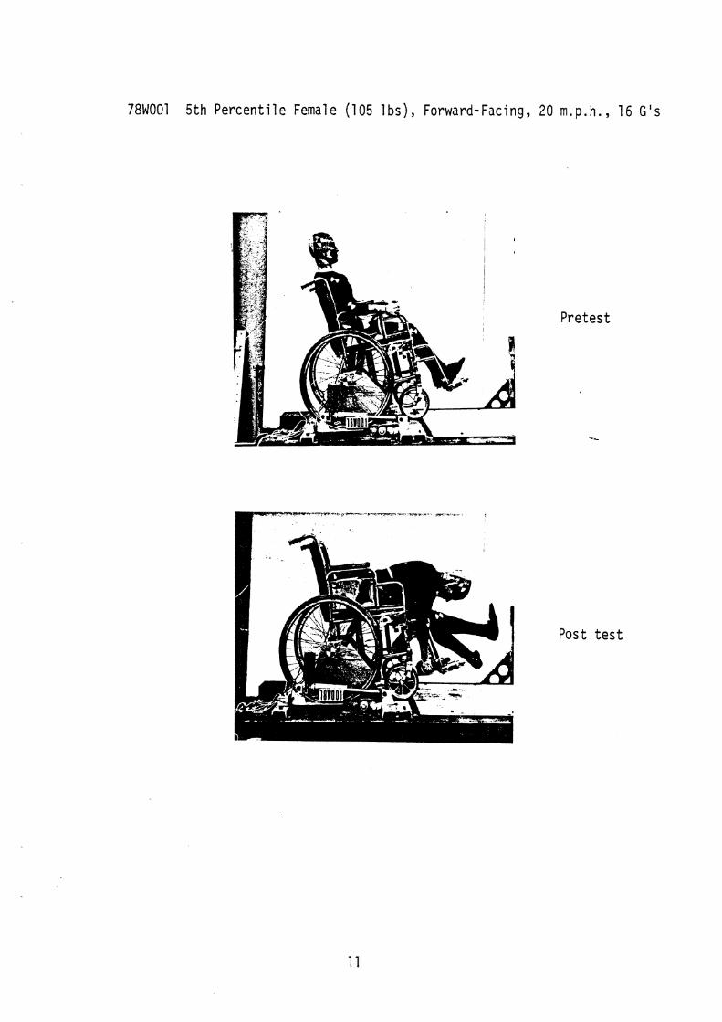
78W001 5 t h P e r c e n t i l e Female (105 l b s ) , Forward-Facing, 20 m.p.h., 16 G ' s
P r e t e s t
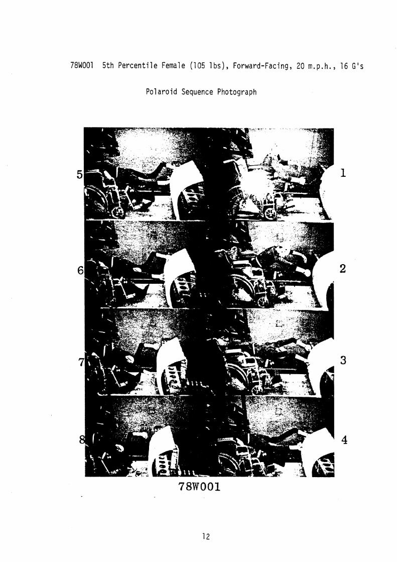
78W001 5th Percentile Female (105 1 bs), Forward-Facing, 20 m.p. h . , 16 G's
Polaroid Sequence Photograph

78W002 50th Percentile Male (160 lbs), Forward-Facing, 20 m . p . h . , 16 G's
Pretest
Post
Post Rear
test
test view

78W003 5 t h P e r c e n t i l e Female (105 I b s ) , 45' o b l i q u e , 20 m.p.h., 16 G 's
P r e t e s t
Post t e s t
Pos t t e s t Rear v iew
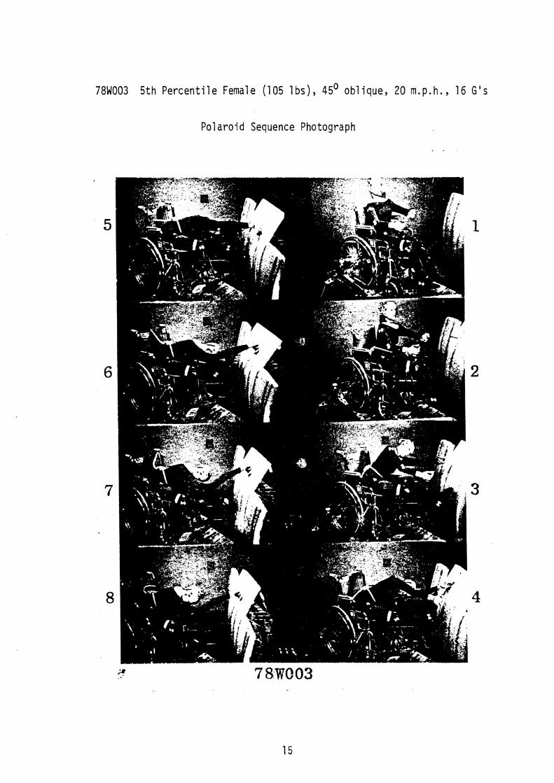
7811003 5 t h P e r c e n t i l e Female (105 1 b s ) , 45' ob l i que , 20 m.p. h . , 16 GIs
P o l a r o i d Sequence Photograph
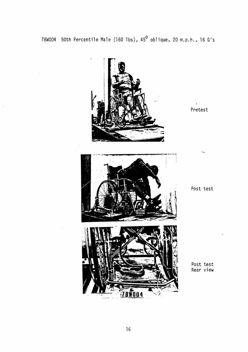
78W004 5 0 t h P e r c e n t i l e Male (160 l b s ) , 45' o b l i q u e , 20 m.p.h., 16 G ' s
P r e t e s t
Pos t t e s t
Post Rear
t e s t v iew
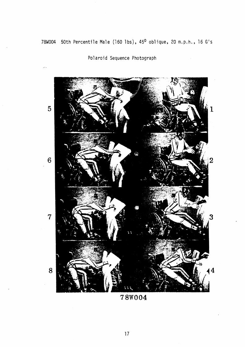
781004 50 th P e r c e n t i l e Male (160 l b s ) , 45O o b l i q u e , 20 m.p.h., 16 G ' s
Pol a r o i d Sequence Photograph
7-