slac ilc program, international bds design, atf2...
TRANSCRIPT

1 May 3, 2005
SLAC ILC program,International BDS Design,
ATF2 facility
Andrei Seryi
May 3, 2005
Seminar at CERN

2 May 3, 2005
Contents
• SLAC ILC program» following the outline given by Tor Raubenheimer
• Very exciting strong program addressing most of the design issues– SLAC program addresses 14 of the 15 “R2” items identified by the 2003
TRC report as well as many additional problems
• Program is focused on overall accelerator design issues as well as a few technology development concepts
• International design of the ILC BDS

3 May 3, 2005
SLAC ILC Program
• Program for FY05/FY06 has six main elements– Electron and Positron sources
– Damping rings
– Beam Delivery System and Interaction Region
– Overall design: Beam parameters, Optics, Emittance preservation,Stability/alignment, Instrumentation, Availability, MPS, and Operational issues
– Conventional construction implications and site development
– Linac rf technology• klystrons, modulators, rf distribution, and possibly couplers
• Wakefields and cavity optimization
• Not SC Cavity fabrication

4 May 3, 2005
System Design• Extensive simulation of sub-systems
– Balance emittance budgets and specify system tolerances impact on overall beam parameters
• Consider operational issues– Design for availability and work on detailed models big impact on
layouts and configuration but hard to quantify
– Develop beam tuning algorithms specify beam instrumentation requirements and layout
– Consider high-level controls software requirements (applications) for beam control specify control system requirements
• Develop Machine Protection Scenarios– Specify active and sacrificial protection systems
– Specify beam dumps and beam tuning stations

5 May 3, 2005
Major Test Facilities• NLCTA
– Complete X-band program
– Create new L-band rf Test Facility• Test klystron and modulators for ILC
• Test normal conducting structures for e+/e- sources
• Construct coupler test facility
– Facilities also available in Klystron Test Lab
• End Station A– Study Interaction Region issues and instrumentation
– Mockup of full IR
• ATF-2– Test BDS using very low emittance beam
• Utilize other test facilities around the world (TTF, SMTF, STF, ATF)

6 May 3, 2005
UK/US/KEK team at ATF, march 2005• MB emittance study• Wiggler study• High quality beam extraction• nm resolution BPM test &
demonstration• Fast feedback test & demonstration
• Fast Kicker for ILC damping ring• Instrumentation developments (LW,
XSR monitor, ODR monitor, • MB-BPM, (SB, MB) longitudinal • feedback, etc.)• Preparation of ‘ATF-2’

7 May 3, 2005
Electron and Positron Source• Electron source
– Continuing photocathode development
– Creating space to begin laser and gun development
• Positron source (program with LLNL)– Studying target design for undulator, conventional, and Compton
sources• Radiation damage
• Thermal shock / beam damage
• Engineering issues (high rotation speed, remote handling)
– NC capture structure design and fabrication
– Capture and optics studies
– Complete E-166 polarized positron production (spring 2005)

8 May 3, 2005
Damping Rings• Damping ring design (program with LBNL)
– Optics and tuning studies
– Collective effects
– Bunch compressor design
• SEY Studies (program with LBNL)– Laboratory measurements in PEL
– Building three chambers for PEP-II installation to verify solutions
• ATF at KEK (for DR and BDS)– Instrumentation (NanoBPM, laser wires, optical anchor)
– Beam studies (ORM, BBA, FBII, Wiggler)
– ATF Kicker replacement
– ATF stripline kicker development
– FONT/Feather
9 May 3, 2005
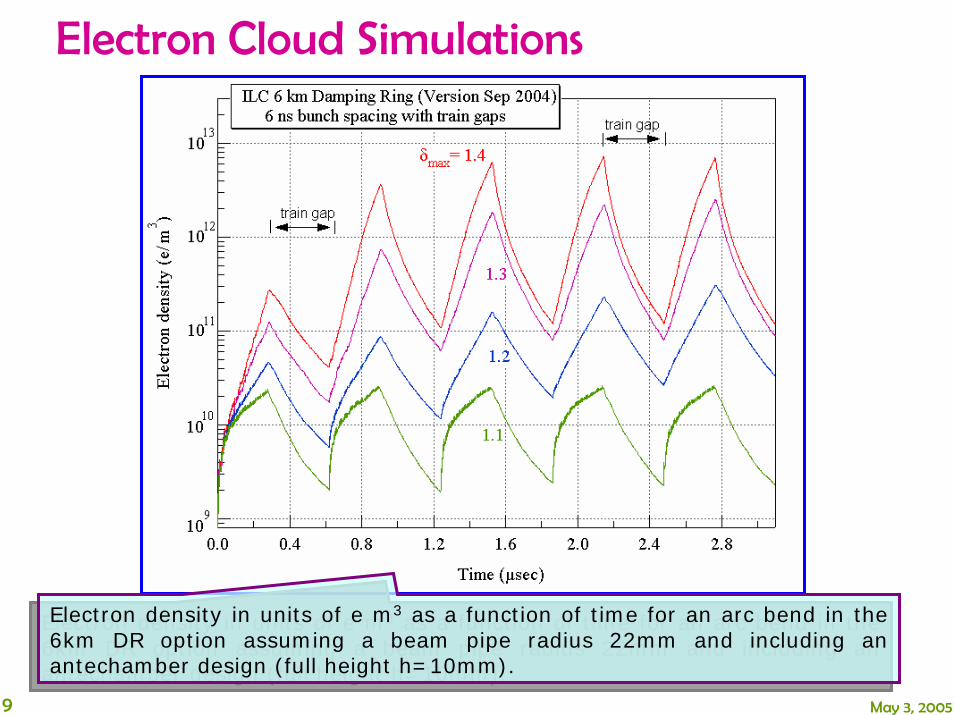
Electron Cloud Simulations
Electron density in units of e m3 as a function of time for an arc bend in the 6km DR option assuming a beam pipe radius 22mm and including an antechamber design (full height h=10mm).
Electron density in units of e m3 as a function of time for an arc bend in the 6km DR option assuming a beam pipe radius 22mm and including an antechamber design (full height h=10mm).

10 May 3, 2005
SEY Studies in PEP LER• Building test inserts chambers for PEP-II
– test chamber with coated samples
– Two ‘grooved’ chambers to verify a proposal by Mauro Pivi and Gennady Stupakov

11 May 3, 2005
Linac Design• Quadrupole alignment
– Use a SC linac quadrupole from DESY to study shunting alignment ability – very important to achieve desired tolerances
– Continue program for NC quadrupoles
• BPM tests (program with TTF, ATF and LCLS)– Develop and test high resolution BPMs
• Cavity diagnostics (program at TTF)– Add HOM detectors to SC cavities at TTF to determine beam-cavity
location – very important especially for high shunt impedance cavities with small aperture
• Measure vibration due to SC cryogenic equipment– Important for conventional layout and BDIR

12 May 3, 2005
Superconducting Quadrupole• Goal–Demonstrate Linac Quad/BPM performance required
for ILC– Verify ~ 5 micron stability of quad magnetic center
– Show ~ 1 micron BPM resolution and < ~ 5micron quad-to-bpmstability in compact, 80 mm aperture design.
• Approach–Test TESLA prototype quad built by CIEMAT in Spain and BPM developed at SLAC
• Plan–Build cryostat for prototype quad and test at Magnetic Measurements Lab with rotating coil. Do beam tests of BPM and eventually integrate quad and BPM for test in LI02

13 May 3, 2005
Cavity HOM Measurements• Understanding HOM signals from TTF
– Instrumentation used to measure HOMs in the TTF cavities
– Analysis was complicated because timing system was noisy
– Seem to achieve resolutions at the 16 micron level
– Questions about relative alignment of modes
– Potential to be very useful
16 um resolution comparing againstother modes

14 May 3, 2005
Wakefield Calculations• Extensive 3-D modeling of the TESLA and the new Low-Loss SC
cavity wakefields– Big computation: 768 processors and requires 300 GB memory
– Mode rotation may be an important source of jitter• Need to understand if this is mostly systematic due to the coupler orientation
or due to fabrication errors
• Huge effect if it is systematic
• New Low Loss cavities have lower cryoloads but higher wakes– Big impact on design may make 35 or 40 MV/m possible
– Need to understand the wakefield implications

15 May 3, 2005
Modulators• ILC baseline modulator was developed in the early 90’s at
FermiLab for use with the TTF• Advantages:
– Simple circuit topology
– Proven design; 10+ years of operation
Disadvantages:
– High stored energy – 270kJ
– Massive pulse transformer – 6.5 tons
– Single-point failures can damage klystron
– Requires large floor area
– Insulating oil – 100’s of gallons
• SLAC effort is evaluating options, e.g.– Marx generator style which should provide
similar efficiency and 100% availability

16 May 3, 2005
Marx Generator Modulator
• Stack of 12 kV units
• Pros– Uses emerging technology
– Modular design for longer MTBF and shorter MTTR
– No oil; compact unit
– No magnetic core
– Finer waveform control
• Cons– Uses emerging technology
– IGBT controls floats at high voltage during the pulse
– DC power flow must be isolated
– Timing signals must cross highvoltage gradients

17 May 3, 2005
Klystrons• Three industrial vendors for ‘baseline’ 10MW MBK tubes
– Still very little real experience with multi-beam klystrons
• Develop L-band sheet beam klystron– an alternate to the MBK tubes
significant cost reduction– High efficiency design using
flat beams instead of 6 beamlets– Smaller with simpler focusing,
cavities, and cathodes
• Study klystron / modulator options– More conservative 5MW tube or lower
power PPM tubes– Decide which (if any) of these to
pursue further

18 May 3, 2005
End Station B Program
• Complete X-band program at NLCTA– Test CERN structure and other gradient studies
– Test active switching technology
– Expect to decommission 8-pac modulator this year
• Start construction of an L-band test facility
• Create facility to construct prototype collimators for the LHC– Adaptation of NLC consumable collimator technology to allow the LHC
to reach design luminosity
• Support E-163 laser acceleration experiment

19 May 3, 2005
ESB L-Band Test Facility• Build L-band test facility in ESB
– Test modulators and klystrons
– Test NC accelerator structures and couplers

20 May 3, 2005
ESB L-Band Test Facility• Modulator will be delivered from SNS this summer
• Scrounging klystron parts from SDI/Anthrax/etc programs
• Buying 5 MW tube from Thales (1 year delivery)
FNAL 2095 KlystronSNS Modulator

21 May 3, 2005
Normal Conducting Structure• Proposed Structure Design for Positron Source with Mechanical
Simplicity, effective cooling and Low Pulsed Heating:– e+ capture: heating 5kW/cell due to RF & 7.5kW/cell due to particle losses
• Working Progress:– Preliminary electrical and cooling design
– Ready to start mechanical design
– Will build 5 cell cavity and operate at NLCTA with 5MW source

22 May 3, 2005
Work on LHC collimation• Create facility to construct prototype collimators for the LHC
– Adaptation of NLC consumable collimator technology to allow the LHC to reach design luminosity
CERN Carbon 1st stage collimator

23 May 3, 2005
End Station A• Significant international interest
– BDS & MDI instrumentation studies, collimator wakefield studies
– Construct IR mock-up

24 May 3, 2005
International design of BDS
• Daresbury, RHUL, QMUL, Oxford, UCL, LAL, CEA/Saclay, CERN, BINP, DESY, INFN, …
• KEK, Tokyo University, Kyoto ICR, IHEP, Pohang AL, …• SLAC, BNL, Fermilab, LLNL, Universities, … and many other …• Truly international efforts• Organization, communication and coherency of efforts is
improving• Estimation > 100 people are involved in machine and machine-
detector aspects of BDS
• Arriving to baseline configuration at the end of 2005 require better organization of existing efforts
• Producing CDR with cost at the end of 2006 require increase of engineering support

25 May 3, 2005
Stages of BDS design toward CDR• Present stage: From concepts to optics &
from boxes on the layout to Geant models – The goal is to mostly finish with this before Snowmass
• Next stage: Performance studies and small optimization of the design & DR to IP studies for the machine & machine-detector performance studies– One iteration of such studies should be done before end of 2005
– impact of parameters (nominal, high luminosity, etc.) on performance
– finalize baseline configuration at the end of 2005
– Ongoing engineering design & test will continue and mature
– Detailed specs for engineering studies
• Third stage: Detailed engineering design; Beam tests; Detector components tests; Civil studies and design; Cost optimization– Impact of parameters & options on cost
– Done during 2006. CDR with cost in Dec.2006

26 May 3, 2005
Strawman configuration is turning into real design
20mrad IR
11mrad big bend
BSY dump line
IP separation 138m (z), 21m (x)
2mrad IRUpstream & downstream diagnostics

27 May 3, 2005
Includes:• energy
spectrometer chicane
• spoilers• absorbers• muon shields• photon masks• PCs• stoppers• instrumentation• feedbackILCFF9 (survivable spoilers)
to IR2
to IR1to dump
11 mrad Big Bend & polarimeter chicane
ILC2005 Beam Switchyard

28 May 3, 2005
2mrad IR: from concept to optics
Version Feb.13“Long FD”
SLAC-BNL-UK-France Task Group

29 May 3, 2005
IR layout for 2o and 2 mrad with SiD and L*=3.5
• IR layout variations with SiD, Large and Huge detector, optimal L*, real sizes of FD magnets, etc., need to be studied– Implications on detector layout, collimation depth (especially 2mrad),
tolerances, background…

30 May 3, 2005
SLAC-BNL-UK-France Task Group2mrad IP Extraction Line in Geant
QD0SD0 QF1
SF1 QEXF1
BYCHICDisrupted beam & Sync radiations
BeamstrahlungIncoming beam
60 m
Shared Large Aperture Magnets
Super Septum Quad
Warm Panofskyseptum quad
Version March 4
Rutherford cable SC quad and sextupole

31 May 3, 2005
Compact SC Final Doublet for 20mrad IR: from idea to full engineering design
BNL

32 May 3, 2005
• Two compact sensors provided to SLAC by PMD/eentec in March 2005 as a results of SBIR program. The size is 5*10*15cm, as requested in specification
• Tests in magnetic field have shown that there is no visible influence of high magnetic field on the MET sensors, so, they can be used as a prototype sensors for the IR region of ILC
IR Stability
standard and compact versions
Case 4: horizontal anti-parallelLeft: 01124040.ap5 B=0TRight: 01125133.ap5 B= -1T
33 May 3, 2005
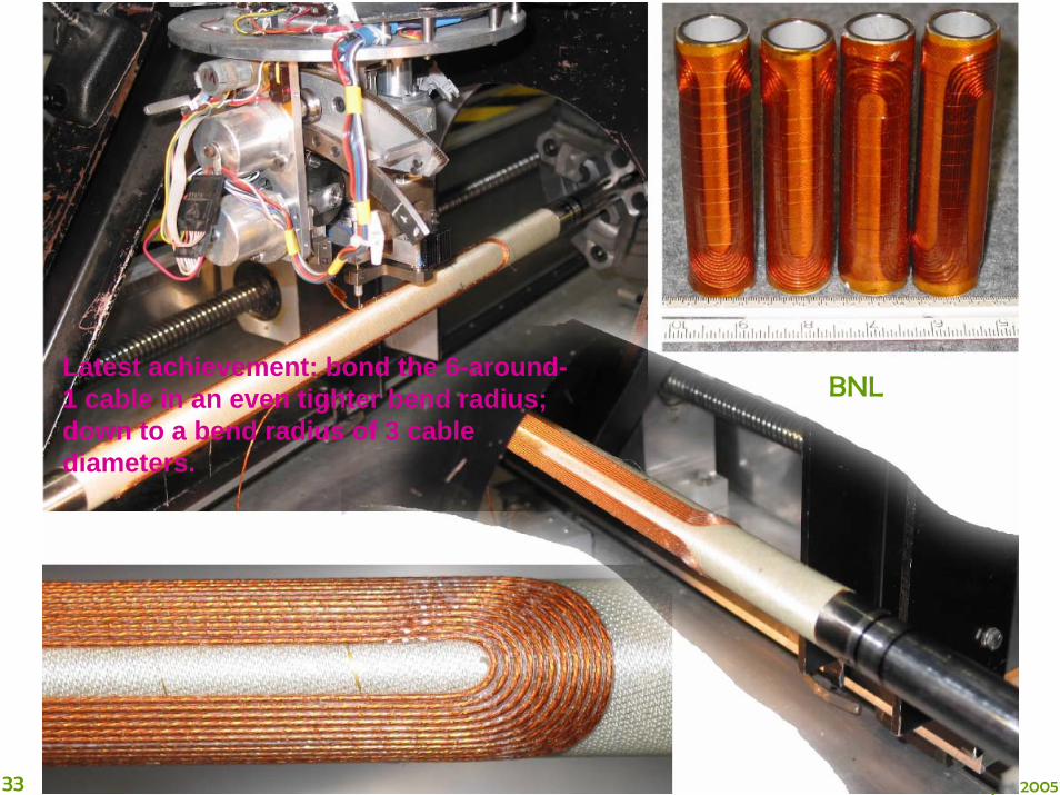
BNLLatest achievement: bond the 6-around-1 cable in an even tighter bend radius; down to a bend radius of 3 cable diameters.

34 May 3, 2005
Antisolenoid and DID in SiD
BNL-Fermilab-SLAC-UK-DESY

35 May 3, 2005
Detailed design of QD0, extraction quad, and antisolenoids
BNL

Detailed comparison of 2omrad and 2mrad IR
20mrad extraction optics 2mrad extraction optics
36 May 3, 2005

Extraction line losses, 20 mrad
Total loss, W
Max density (W/m) in SCQ / WQ/ bend/ drift
500 GeV nom. 0 0 / 0 / 0 / 0
500 GeV high L 1859 1.8 / 49 / 42 / 311 TeV nom. 187 0 / 1.2 / 4.1 / 4.11 TeV high L 97490 496 / 4025 / 2481 / 1352
Total loss, W
Max density (W/m) in SCQ / WQ/ bend/ drift
4.9 0 / 0.42 / 0.12 / 0.43
13280 0 / 308 / 383 / 9503384 0 / 106 / 79 / 254312557 559 / 4968 / 8144 / 13101
Ideal collision at IP Large vertical offset between beams at IP
37 May 3, 2005
Extraction line losses, 2 mrad (less detailed study)Loss (W) in QD0/QEXF1/Coll
500 GeV nom. 0 / 0 / ~20000
500 GeV high L ~250 / ~50 / ?1 TeV nom. 0 / 0 / ?1 TeV high L ? / ? / ?
Ideal collision at IPLoss (W) in QD0/QEXF1/Coll 0 / 0 / ~20000
~350 / ~400 / ?0 / 0 / ?? / ? / ?
Large vertical offset between beams at IP

38 May 3, 2005
Standard SLAC BSY Copper Protection Collimator Rated at 20 kW
Reference: The Stanford Two-Mile Accelerator, R. Neal, 1968
28 cm
Vertical cooling passages drilled on either sideof the gap and cooling loops around outside ofthe body

39 May 3, 2005
Collimation and energy deposition studies
ILC-FF9 βx*βy=6E5 m2
IP
10-3 Halo
Fermilab-SLAC-UK-DESY

40 May 3, 2005
Pre and post IP polarimeters & E-spectrometers

41 May 3, 2005
• ILC optimistic: tracked = 121nm * 4.37 nm (geometrical is 87.6nm * 4.29nm )
• ILC w/e+e- (at beta 3mm/0.3mm): tracked = 323nm * 5.21nm (geometrical is 247.6nm * 4.95nm)
• Correspondingly, the luminosity with tracked beams are:
• ILC optimistic: 8.48e+34 instead of 11.8e34 in the table, i.e. 72%
• ILC w/e+e- : 2.67e+34 instead of 5.9e34 in the table, i.e. 45%
34
Gamma-gamma with nominal pars.

42 May 3, 2005
ATF-2 at KEK• ATF-2 would be BDS test
– Follow-on to FFTB
– New FFS optics
– Operational issues

43 May 3, 2005
BDS design and ATF-2 facility• Many reasons to develop the ATF-2
– Luminosity issues will be extremely challenging in the LC• Likely more challenging than achieving the beam energy
– Complete FFTB studies• FFTB never demonstrated routine operation of FFS• Need to implement full feedback control and optimization• Operate with ILC like bunch train and demonstrate IP feedback• Operate with stable low emittance beam from ATF DR
– Provide demonstration and experience concurrent with ILC construction
• FFTB experience will be over 15 years old
• Train new generation of physicists• Provide a visible test facility for
project reviewers and sponsors

44 May 3, 2005
New final focus
Configuration with bends to avoid crab-cavity test area
(A) Small beam size(A1) Obtain σy ~ 35nm(A2) Maintain for long time
(B) Stabilization of beam center (B1) Down to < 2nm by nano-BPM (B2) Bunch-to-bunch feedback of
ILC-like train
ATF2 Goals & stages:

As ILC, ATF2 critically depends on instrumentation
45 May 3, 2005
• BSM to confirm 35nm beam size
• nano-BPM at IP to see the nm stability
• Laser-wire to tune the beam
• Cavity BPMs to measure the orbit
• Movers, active stabilization, alignment system
• Kickers to produce ILC-like train

46 May 3, 2005
Summary
• SLAC ILC program – strong efforts on many fronts
• BDS design is making progress from the concept to optics, from optics to engineering design
• The worldwide BDS group is organizing its work
• There is a lot to do to arrive with a CDR with cost– Arriving to baseline configuration at the end of 2005
require better organization of existing efforts
– Producing CDR with cost at the end of 2006 require increase of engineering support