skp engineering college -...
TRANSCRIPT

Civil Engineering Department
SKP Engineering College
Tiruvannamalai
Department of Civil Engineering
SKP Engineering College
Tiruvannamalai
55 Surveying I
SKP Engineering College
Tiruvannamalai – 606611
A Course Material
on
Surveying I
BY
SANKAR.S
Assistant Professor
Department of Civil Engineering
SKP Engineering College
Tiruvannamalai -606611
Surveying I

S.K.P. Engineering College, Tiruvannamalai V SEM
Civil Engineering Department 2 surveying I
Quality Certificate
This is to Certify that the Electronic Study Material
Subject Code: CE 6404
Subject Name: SURVEYING I
Year/Sem: II / III
Being prepared by me and it meets the knowledge requirement of the University curriculum.
Signature of the Author
Name: .Sankar.S
Designation: Assistant Professor
This is to certify that the course material being prepared by Mr.S.Sankar is of the adequate quality. He
has referred more than five books and one among them is from abroad author.
Signature of HD Signature of the Principal
Name: A.Saravanan Name: Dr.V.Subramania Bharathi
Seal: Seal:
S.K.P. Engineering College, Tiruvannamalai V SEM
Civil Engineering Department 3 surveying I
CE6304 SURVEYING I L T
P C
OBJECTIVES:
To introduce the principles of various surveying methods and applications
to Civil
UNIT I FUNDAMENTALS AND CHAIN SURVEYING 9
Definition- Classifications - Basic principles-Equipment and accessories for
ranging and chaining – Methods of ranging - well conditioned triangles – Errors in
linear measurement and their corrections - Obstacles - Traversing – Plotting –
applications- enlarging the reducing the figures – Areas enclosed by straight line
irregular figures- digital planimetre.
UNIT II COMPASS AND PLANE TABLE SURVEYING 9
Compass – Basic principles - Types - Bearing - Systems and conversions- Sources
of errors- Local attraction - Magnetic declination-Dip-Traversing - Plotting -
Adjustment of closing error – applications - Plane table and its accessories -
Merits and demerits - Radiation - Intersection - Resection – Traversing- sources of errors
– applications.
UNITIII LEVELLING 9
Level line - Horizontal line - Datum - Bench marks -Levels and staves -
temporary and permanent adjustments – Methods of levelling - Fly levelling - Check
levelling - Procedure in levelling - Booking -Reduction - Curvature and refraction -

S.K.P. Engineering College, Tiruvannamalai V SEM
Civil Engineering Department 4 surveying I
Reciprocal levelling – Sources ofErrors in levelling- Precise levelling - Types of
instruments - Adjustments - Field procedure
UNIT IV LEVELLING APPLICATIONS 9
Longitudinal and Cross-section-Plotting - Contouring - Methods - Characteristics and uses
of contours – Plotting – Methods of interpolating contours – Computations of cross
sectional areas and volumes - Earthwork calculations - Capacity of reservoirs - Mass
haul diagrams.
UNIT V THEODOLITE SURVEYING
Theodolite - Types - Description - Horizontal and vertical angles - Temporary and
permanent adjustments – Heights and distances– Tangential and Stadia
Tacheometry – Subtense method.
.

S.K.P. Engineering College, Tiruvannamalai V SEM
Civil Engineering Department 1 surveying I
CONTENTS
S.No Particulars Page
1 Unit – I 2
2 Unit – II 52
3 Unit – III 69
4 Unit – IV 111
5 Unit – V 121

S.K.P. Engineering College, Tiruvannamalai V SEM
Civil Engineering Department 2 surveying I
UNIT-I
INTRODUCTION AND CHAIN SURVEYING
PART-A
1. Describe the principle of surveying. (CO1-L1-AUC Apr/May2011) (AUC
Nov/Dec2011)
Thefundamental principles upon which thesurveyingisbeing carriedoutare
�Working from whole to part.
� After deciding the position of anypoint, itsreference must bekeptfrom at least two
permanentobjectsor stationswhose positionshave alreadybeenwell defined.
2. What is the purpose of an optical square? (CO1-L1-AUC Apr/May2011
Itismoreaccuratethanthecrossstaffanditcanbeusedforlocatingobjectssituatedatlarger
distances. Itissmall and compact handinstrumentandworksontheprinciple ofreflection.
3. Give the conventional signs for BenchMark and Cultivated land. (AUCApr/May2010)
4. What do you mean by reciprocal ranging?
(AUCApr/May2010)

S.K.P. Engineering College, Tiruvannamalai V SEM
Civil Engineering Department 3 surveying I
When theendstationsarenotintervisibleduetohigh groundora hilloriftheendsaretoo
long.Insuchcases,intermediatepointscanbe fixedonthesurveylineby aprocessknownas
Reciprocal rangingor Indirect ranging.
5. What do you mean by scalein surveying? (CO1-L1-AUC Nov/Dec2011)
Scaleisa fixed ratio thatevery distanceontheplanbearswithcorrespondingdistanceon the
ground. For example:1cm =10m.
6. Define and distinguish between plane and geodetic surveying. (CO1-L1-AUC Nov/Dec2011)
S.No Plane Surveying Geodetic Surveying
1
It isa processofsurveyingin which the
portionof theearthbeing
surveyedis consideredaplane.
It isa processofsurveyingin which theshape
and size oftheearthareconsidered.
2
Surveysforthelocationand
constructionofhighwaysandroads,
canals,landingfields, and
railroadsare classifiedunder plane
Thepositionsare expressedas latitudes(angles
northorsouthofthe Equator)andlongitudes
(angles eastorwestofaprimemeridian)oras
3
Inthistraining manual,we will discuss
primarilythemethods usedin
plane surveyingrather thanthose
Themethods usedingeodetic surveyingare
beyondthescopeofthistrainingmanual.
S.K.P. Engineering College, Tiruvannamalai V SEM
Civil Engineering Department 4 surveying I
7. Define conditioned triangles.(AUC Nov/Dec2010)
Theaccuracy ofatriangulationsystem,inwhichany errorinangular measurementhas a
minimumeffectuponthecomputedlengths, isknown aswell-conditionedtriangle.
8. Explain the range of reciprocal ranging. (CO1-L1-AUC
May/June 2013)
The vision rangingand line rangercan be adopted onlywhen the end stations are inter-
visible.Thelineofsightbetween twostationsisobstructedby naturalorman-madeobjectsornot
clearlyvisible.Undersuch conditions, indirect orreciprocal rangingisapplicable.
9. What do you mean by plane surveying? (CO1-L1-AUC May/June 2013)
Plane surveyingisa process ofsurveyinginwhich the portion ofthe earth beingsurveyed is
consideredaplane. In thistrainingmanual,weusedinplanesurveyingratherthan those usedin
geodeticsurveying.
10.What is meant by geodetic surveying?(AUC Nov/Dec2012)
Geodetic surveyingis a process ofsurveyingin which the shape and sizeofthe earth are
considered.Themethodsused ingeodeticsurveyingarebeyondthescopeofthis trainingmanual.
11.What do you require indirect ranging? (CO1-L1-AUC Nov/Dec2012)
TwointermediatepointsC1 andD1 areselectedwhicharenotalongthelineofsightAB
(surveyline).StationsC1 andD1 areapproximatelyinlinesuchthatlineC1 D1 isapproximately
paralleled toAB.C1issosituated thatbothD1andB arevisible fromit,while fromD1bothA andC1
canbesighted.
12.Name thedifferent methods adoptedin scale of aplan/map.( CO1-L1-AUC May/June
2012)
S.K.P. Engineering College, Tiruvannamalai V SEM
Civil Engineering Department 5 surveying I
�Plain Scale
�Diagonal Scale
�VernierScale
�Scale ofchords
13.What are arrows? (CO1-L1-AUC
Nov/Dec2009)
Arrowsarealsocalledmarkingorchainingpins,andare used to markthe endofeach chain
during theprocessof chaining.
14.What is plumbBob? (CO1-L1-AUC Nov/Dec2009)
PlumbBobisusedtolocatepointsdirectlybelow oraboveanotherpoint.Itisalsousedfor
accurately centeringofcompassorlevelortheodoliteoverastationmark,and fortestingthe
verticalityofrangingpoles.
15.Define surveying.
Surveyingisdefinedasthescienceofmakingmeasurementsoftheearthspecifically the
surfaceof theearth.
16.Wha tare the works of a surveyor in office?
Inofficework,convertingfieldmeasurements(alsocalledreducing)involvestheprocess of
computing,adjusting,and applyinga standardrule tonumerical values.
17.What are the types of corrections to beapplied?
�CorrectionforLength.

S.K.P. Engineering College, Tiruvannamalai V SEM
Civil Engineering Department 6 surveying I
�Correctionfor Temperature.
�CorrectionforPull.
�CorrectionforSag.
�CorrectionforSlope.
S.K.P. Engineering College, Tiruvannamalai V SEM
Civil Engineering Department 7 surveying I
18.What are the instruments usedinchainsurveying?
a)Instrumentsused for measuringdistances
�Chain
�Tape
b)Instrumentsused for markingsurveystations
�Ranging rod
�Offset rod
�Laths andwhites
�Pegs
c)Instrumentsusedforsettingrightangles
�Cross staff
�Optical square
d)Otherinstruments:
�Arrow
�Plumbbob
19.What are the different types of errors inlinear measurement?
a) Instrumental errors
b) Observational
errors

S.K.P. Engineering College, Tiruvannamalai V SEM
Civil Engineering Department 8 surveying I
�GrossErrors
�SystematicErrors
�Accidentalorrandomerrors
20.What is meant by direct ranging?
Whenintermediaterangingrodsarefixedonastraightlinebydirectobservationfromend
stations, theprocess isknown asDirectranging.
21.What are the conventional signs used to denote the following.
(i) Road(ii) railwaysingleline (iii) railwaydoubleline(iv)bridge(v)pond and stream
(vi)church(vii)canal lock (viii) chain
line.
S.No Description Symbol
1 Road
2 Railwaysingleline
3
Railwaydoubleline
4
Bridge
S.K.P. Engineering College, Tiruvannamalai V SEM
Civil Engineering Department 9 surveying I
1. Write short noteson
a) AnEngineerschain.
PART-B (16marks)
b) Crossstaff. (CO1-H1-
AUCApr/May2011)
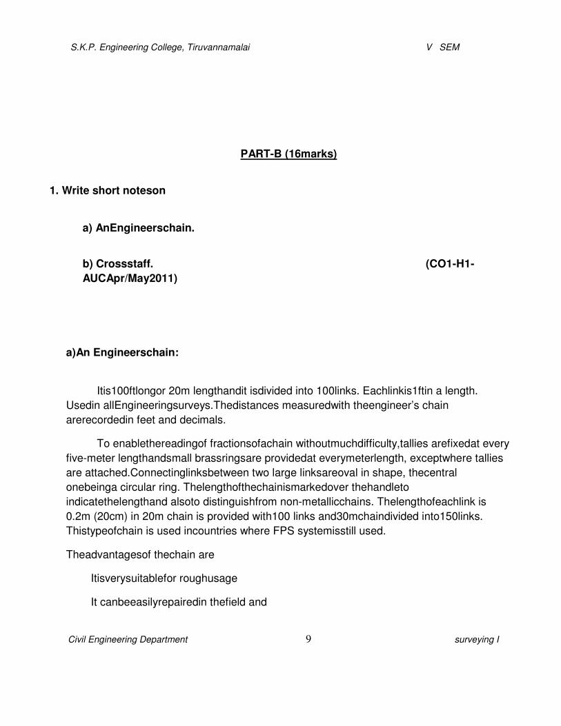
a)An Engineerschain:
Itis100ftlongor 20m lengthandit isdivided into 100links. Eachlinkis1ftin a length.
Usedin allEngineeringsurveys.Thedistances measuredwith theengineer’s chain
arerecordedin feet and decimals.
To enablethereadingof fractionsofachain withoutmuchdifficulty,tallies arefixedat every
five-meter lengthandsmall brassringsare providedat everymeterlength, exceptwhere tallies
are attached.Connectinglinksbetween two large linksareoval in shape, thecentral
onebeinga circular ring. Thelengthofthechainismarkedover thehandleto
indicatethelengthand alsoto distinguishfrom non-metallicchains. Thelengthofeachlink is
0.2m (20cm) in 20m chain is provided with100 links and30mchaindivided into150links.
Thistypeofchain is used incountries where FPS systemisstill used.
Theadvantagesof thechain are
�Itisverysuitablefor roughusage
�It canbeeasilyrepairedin thefield and

S.K.P. Engineering College, Tiruvannamalai V SEM
Civil Engineering Department 10 surveying I
�It canbeeasilyread.
S.K.P. Engineering College, Tiruvannamalai V SEM
Civil Engineering Department 11 surveying I
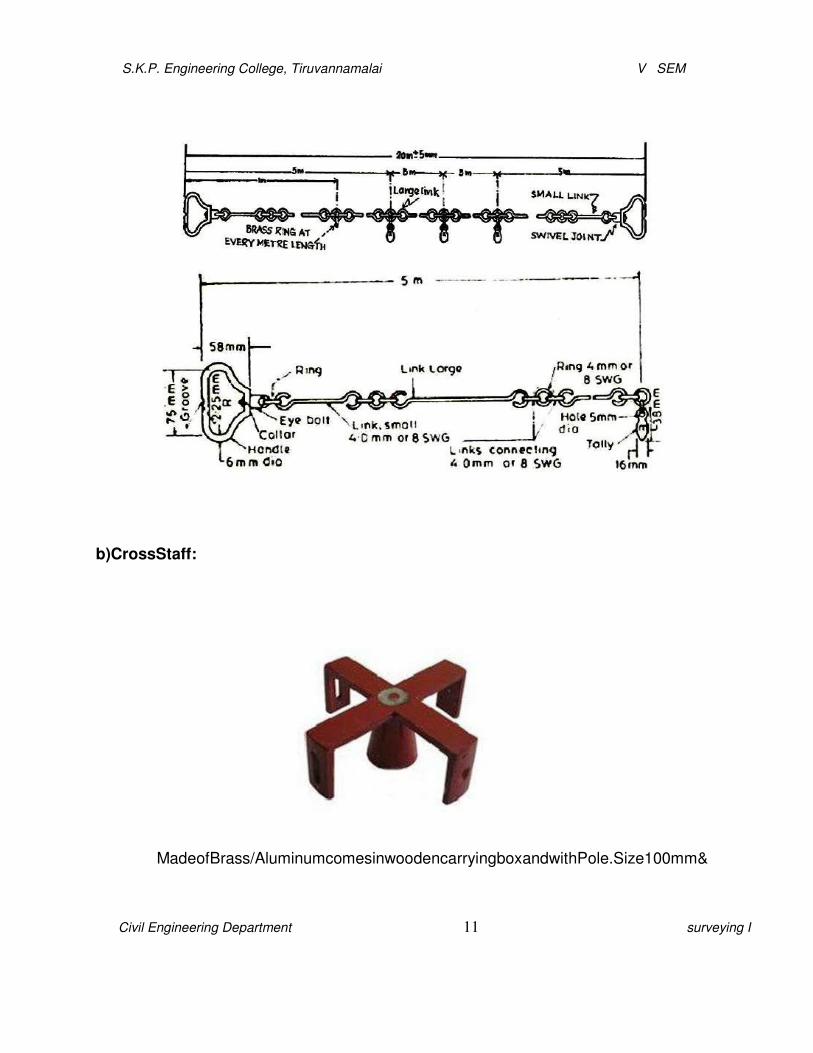
b)CrossStaff:
MadeofBrass/AluminumcomesinwoodencarryingboxandwithPole.Size100mm&
S.K.P. Engineering College, Tiruvannamalai V SEM
Civil Engineering Department 12 surveying I
150mm available.
Cross-staffisused for(i)findingthe footoftheperpendicularfromagivenpointtoaline,
and(ii)settingoutarightangleatagivenpointonaline.Therearetwotypesofcross-staff,
namely,(1)theopenand (2) theFrench,thefirst one beingincommonuse.
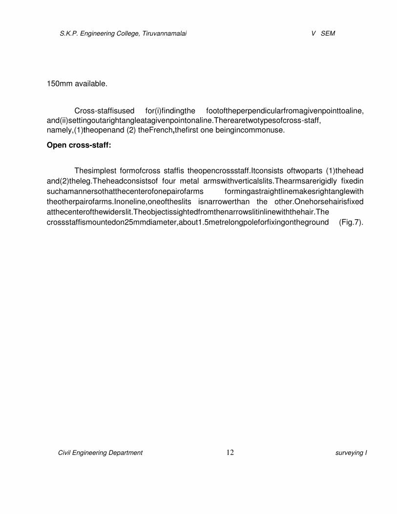
Open cross-staff:
Thesimplest formofcross staffis theopencrossstaff.Itconsists oftwoparts (1)thehead
and(2)theleg.Theheadconsistsof four metal armswithverticalslits.Thearmsarerigidly fixedin
suchamannersothatthecenterofonepairofarms formingastraightlinemakesrightanglewith
theotherpairofarms.Inoneline,oneoftheslits isnarrowerthan the other.Onehorsehairisfixed
atthecenterofthewiderslit.Theobjectissightedfromthenarrowslitinlinewiththehair.The
crossstaffismountedon25mmdiameter,about1.5metrelongpoleforfixingontheground (Fig.7).

S.K.P. Engineering College, Tiruvannamalai V SEM
Civil Engineering Department 13 surveying I
Forlayingoutarightangleatapointonthechainline,thecrossstaffisheldvertically on
thesupportingpoleatthe givenpoint.Rangingrodis fixedonthechain lineoneithersideofthe cross
staffandsighted through theslitandhorse hair. The crossstaffis turned tilltherangingrod is
visible.Atthistime,onesightthroughtheotherpairofslitsandanotherpersonfixesarangingrod
inthislineofsight.Footofthecrossstaffjoinedwiththerangingrodgivesperpendicularlinewith
thechain line.
2. Give A list of sources Of error in chainsurveyand Say which of the are cumulative And
Whicharecompensating? (CO1-H1-AUC May/June 2012)( CO1-
H1-AUCApr/May2011) Errorsin Chaining:
a) Instrumental errors,
and b) Observational
errors.
a) Instrumentalerrors:
Instrumental errorsarecausedbyimperfectionsin instruments,wearand tear of
instrumentsduetocontinuoususeandtheir roughhandling. Instrumentsarethusrequiredtobe

S.K.P. Engineering College, Tiruvannamalai V SEM
Civil Engineering Department 14 surveying I
testedforaccuracy, adjustedandcalibratedatfrequentintervals to ensurethat theresultsof
surveyingexercisesare wellwithin theprescribed limitsofaccuracyandtolerances.
b)Observationalerrors:
Observationalerrorsareintroducedbecauseofinvolvementofhuman factorinsurveying
process.Itshouldbeacceptedthatwheneverahumanelementisinvolved,theprocessresultwill
beinfluencedby theattitude,efficiency andperceptionofindividualhumanbeinginasubjective
manner. Thesecan beavoidedbypropertrainingofsurveyors,prescribingadequateandsuitable
precautions tobeundertakenineachobservationalandmeasurementprocess,andspecifying
properand detailed methodstatementsforperformingeachoperationoftheprocess.
Boththesetypesoferrors,i.e.instrumental and observational,canbefurtherclassifiedinto:
i. Grosserrors,
ii. Systematicerrors, and
iii. Accidentalorrandomerrors.
i) Grosserrors:
Grosserrorsormistakesareblundersthatoccurduetoinexperienceorcarelessnesson
thepart ofthesurveyor. In chain surveying,thesecould bedueto
�displacementorlossofpegsorarrows,providedtoidentifyandfixthelocationofvarious
typesofstationsandotherplacesofinterest.

S.K.P. Engineering College, Tiruvannamalai V SEM
Civil Engineering Department 15 surveying I
�reading thechain or tapein awrong manner orusinganinstrumentinanincorrectway,and
�Wrongrecodingof measurementsintherecord book,e.g.field book.
Thereisno room for grosserrorsorblundersinthesurveyingprocesses.If grosserrorsare
detected,theentiresurveyingprocessandmeasurementsare requiredtoberepeatedafresh,
resultinginsubstantiallossoftimeandresources.Sucherrorscanbeavoidedbypropertraining
andtestingofsurveyors,adoptingstandard procedures,evento the
minutedetailsandcarryingout thesurveyworkwith utmostcare.
ii)Systematic errors:
Systematicerrorsfollow somespecificpatternaccordingtosome
mathematicalorphysical law.The errorcould be cumulative,i.e.occurringin the samedirection
and tends to accumulate affectingtheaccuracy ofmeasurementstoa greatextent.In
thecontextofchainsurveying, these could bedueto:
�Erroneouslengthof chain or tape (+ve or–ve),
�Erroneousranging,
�Links in chain notstraight (local bends) duetoroughhandlingortwistingof metallic tapes,
�Non-horizontallyofchain/tapeoverroughgroundterrain,
�Saginchain ortape, whenitisstretchedacrossa depressioninground,
�Variationin temperatureand/or dampness, and
�Variationin pull appliedduring measurement.
These errorscould be identified and adjusted and can be modeled.Suitable
corrections can beappliedto the measurements for obtaining greater accuracy. Following
aresome of the important correctionsapplied tomeasurementsusingchain or tape:
�CorrectionforErroneous Lengthof Chain/Tape:

S.K.P. Engineering College, Tiruvannamalai V SEM
Civil Engineering Department 16 surveying I
Thechainsurveyingdependsonly onlinearmeasurementofdistances.Fortraversingonly
the errorsindistancemeasurementsareofimportanceandsignificance.Measuringdeviseeither
chainortapecaneitherbelongerorshorterthanthedesignatedlength.Themeasureddistance
willbesmallerthanthe actualifthelengthofchainislongerthan thedesignatedlength.Itwill be
largerthan the actual ifthe chain isshorter than the designated length. The actual measured
distance canbecorrected bythefollowingformula:
�L'�
TrueorCorrectDistance=� �X measured distance
�L�
where, L′=Actual incorrect lengthofchain,and
L= Designatedlengthofchain.
�CorrectionforTemperature:
Correctionfor temperatureisapplied if the temperature in thefield is more than
the temperatureatwhichthetape/chainwasstandardized.Thiscorrection(Ct)isgivenbythe
following
formula:
Ct��α (Tm��To)L
Where,α= Coefficient ofthermalexpansion,
Tm= Mean temperature inthefield duringmeasurement,
To= Standardtemperaturefor the tape,and
L=Measureddistance.

S.K.P. Engineering College, Tiruvannamalai V SEM
Civil Engineering Department 17 surveying I
�CorrectionforPull:
�P��Po�L
CP=��
�AE �
Where,P=Pull appliedduring measurements(kg or
N), Po=Standardpull,
L=Measuredlength,
A=Cross-sectional areaof thetape(cm2ormm2),and
E=Young’smodulus ofelasticity(kg/cm2orN/mm2).
�CorrectionforSag:
Correctionforsagisappliedwhenthetapeisstretchedon supportsbetweentwopoints,it
takes the formofahorizontalcatenary. Thehorizontaldistancewillbelessthan the distancealong
thecurve.Thedifferencebetweenhorizontaldistanceandthemeasuredlengthalongcatenary is
calledsagcorrectionanditisalwaysnegative.
L�wL�2
CS=
24n2P2

S.K.P. Engineering College, Tiruvannamalai V SEM
Civil Engineering Department 18 surveying I
Whenunit weightisgiven,
L�W�2
CS=
24n2P2
Where,L= thelengthof thetape(inm) suspendedbetween
thesupports, P=Pull appliedin kgor N, and
w=Weight ofthetapeinkg or N per m run.
W=Total weight oftapeinkg
n= Numberofspans
iii) RandomorAccidental Errors:
RandomorAccidentalerrorscan occurdue tolackofperfectionofhumaneyeandor
human behavior.Even the bestand efficientsurveyorcan have fatigue effectafterworking
forlong durationinstrenuousenvironmentcausingobservationalerrors.The
randomerrorscannotbe eliminated entirely,whateverprecautions areundertaken. These
may,however,occurin either direction and hence,tend to compensate and,
thus,arenotserious innature. These normallyfollow
thelawofchanceand,thus,canbeanalysedwiththehelpofprobability theory.Usingsuitable
probabilitydistribution functions,theseerrorscanthenbeadjusted,distributed amongvarious
measurementsandaccounted for.Each surveyingmethodorprocesscanbeassigneda reliability
factor (orriskfactor) foraccuracydependingontheanalysisofprobabilitybehavior.

S.K.P. Engineering College, Tiruvannamalai V SEM
Civil Engineering Department 19 surveying I
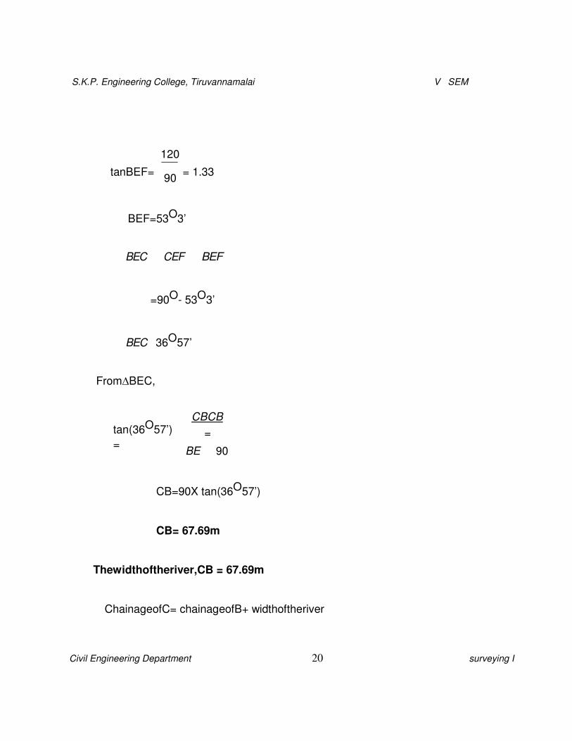
3. AsurveylineABCcrossingariveranglescutsitsbanksatBandC.Todeterminethe width
BCoftheriver.Thefollowingoperationwascarriedout.A pointEwasestablishedonthe
perpendicularBE suchthat angle CEFis arightanglewhereFis apoint on thesurveyline.
If thechainageofFandBarerespectively1200mand1320mandthedistanceEBis90m.
Calculatethewidth of the riverandalsothechainageofC. (CO1-H1-
AUCApr/May2011)
BF=ChainageofB–Chainageof F
= 1320–1200
BF=120m
From ∆EBF,
S.K.P. Engineering College, Tiruvannamalai V SEM
Civil Engineering Department 20 surveying I
tanBEF=
120
90
= 1.33
BEF=53O3’
�BEC��CEF��BEF
=90O- 53O3’
�BEC�36O57’
From∆BEC,
tan(36O57’)
=
CBCB
=
BE 90
CB=90X tan(36O57’)
CB= 67.69m
Thewidthoftheriver,CB = 67.69m
ChainageofC= chainageofB+ widthoftheriver

S.K.P. Engineering College, Tiruvannamalai V SEM
Civil Engineering Department 21 surveying I
=1320+ 67.69
ChainageofC= 1387.69m

S.K.P. Engineering College, Tiruvannamalai V SEM
Civil Engineering Department 22 surveying I
4. Explainthemethodsofchainingwhilethereare obstaclessuchasbuilding orriver.
(CO1-H1-AUC Nov/Dec2011) (CO1-H1-AUC May/June 2012)( CO1-H1-AUCApr/May2010)
Inthiscaseit is requiredtoprolong thechain linebeyond theobstacle andtofindthe
distance acrossit. Inthiscasethetypical obstacle is abuilding. Oneofthefollowingtwo
methods maybeadopted.
Firstmethod:
Onone sideofthechain lineAB, two pointsPandQareselected.Perpendicularsofequal
lengthPP’ and QQ’ areerected. ThelineP’Q’ isextended till thebuildingispassed. Onthe
extended line,two points R and Sareselected. The perpendicularat Rand
Saresoerectedsuch that RR’ =SS’= QQ’ = PP’.thenthepoints P’, Q’, R’and S’ will lie on
thesameline.ThenQ’R =
QR andthedistanceQ’R’ is measuredtoset QR, thenthelineisextended.
Second method:
Thismethodisalso equallyapplicable for thiscondition.Two pointsPandQonthechain
lineAB areselectedontheone sideofthechain line.A perpendicular QRiserectedat Q suchthat
QR = PR. PointsPandR arejointedand extendeduptoS. A perpendicularSV isset at S
suchthat PS =SV.OnthelineSVa point T ismarkedsuchthatST = SR.with
Vascentreandradius equal toQR cutanarcsuchthatPQ = QR=VT =UT. ThenU and
Vareonthechain lineAB. The distance RTismeasured. Thustheobstructedlength, QU= RT.
S.K.P. Engineering College, Tiruvannamalai V SEM
Civil Engineering Department 23 surveying I
5. Describethe construction andworking ofanopticalsquarewith aneatsketch.
(CO1-H1-AUCApr/May2010)
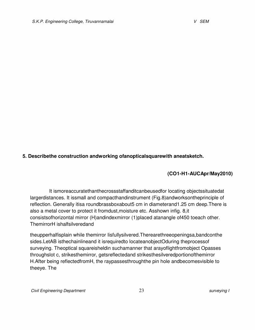
It ismoreaccuratethanthecrossstaffanditcanbeusedfor locating objectssituatedat
largerdistances. It issmall and compacthandinstrument (Fig.8)andworksontheprinciple of
reflection. Generally itisa roundbrassboxabout5 cm in diameterand1.25 cm deep.There is
also a metal cover to protect it fromdust,moisture etc. Asshown infig. 8,it
consistsofhorizontal mirror (H)andindexmirror (1)placed atanangle of450 toeach other.
ThemirrorH ishalfsilveredand
theupperhalfisplain while themirror Iisfullysilvered.Therearethreeopeningsa,bandconthe
sides.LetAB isthechainlineand it isrequiredto locateanobjectOduring theprocessof
surveying. Theoptical squareisheldin suchamanner that arayoflightfromobject Opasses
throughslot c, strikesthemirror, getsreflectedand strikesthesilveredportionofthemirror
H.After being reflectedfromH, the raypassesthroughthe pin hole andbecomesvisible to
theeye. The
S.K.P. Engineering College, Tiruvannamalai V SEM
Civil Engineering Department 24 surveying I
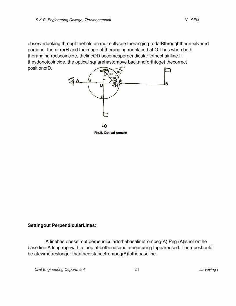
observerlooking throughthehole acandirectlysee theranging rodatBthroughtheun-silvered
portionof themirrorH and theimage of theranging rodplaced at O.Thus when both
theranging rodscoincide, thelineOD becomesperpendicular tothechainline.If
theydonotcoincide, the optical squarehastomove backandforthtoget thecorrect
positionofD.
Settingout PerpendicularLines:
A linehastobeset out perpendiculartothebaselinefrompeg(A).Peg (A)isnot onthe
base line.A long ropewith a loop at bothendsand ameasuring tapeareused. Theropeshould
be afewmetreslonger thanthedistancefrompeg(A)tothebaseline.
S.K.P. Engineering College, Tiruvannamalai V SEM
Civil Engineering Department 25 surveying I
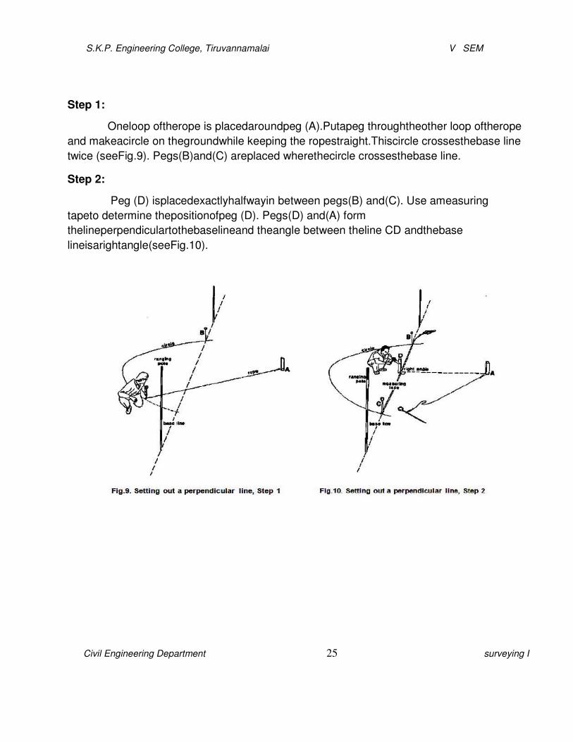
Step 1:
Oneloop oftherope is placedaroundpeg (A).Putapeg throughtheother loop oftherope
and makeacircle on thegroundwhile keeping the ropestraight.Thiscircle crossesthebase line
twice (seeFig.9). Pegs(B)and(C) areplaced wherethecircle crossesthebase line.
Step 2:
Peg (D) isplacedexactlyhalfwayin between pegs(B) and(C). Use ameasuring
tapeto determine thepositionofpeg (D). Pegs(D) and(A) form
thelineperpendiculartothebaselineand theangle between theline CD andthebase
lineisarightangle(seeFig.10).
S.K.P. Engineering College, Tiruvannamalai V SEM
Civil Engineering Department 26 surveying I
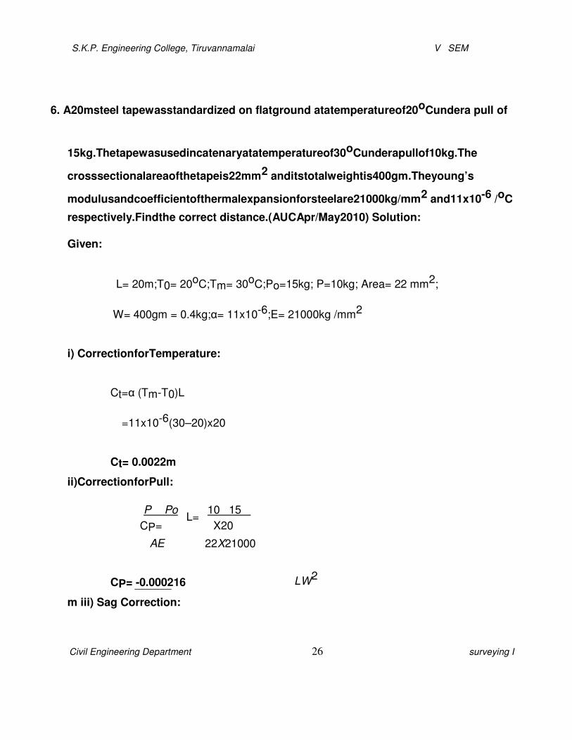
6. A20msteel tapewasstandardized on flatground atatemperatureof20oCundera pull of
15kg.Thetapewasusedincatenaryatatemperatureof30oCunderapullof10kg.The
crosssectionalareaofthetapeis22mm2 anditstotalweightis400gm.Theyoung’s
modulusandcoefficientofthermalexpansionforsteelare21000kg/mm2 and11x10-6 /oC
respectively.Findthe correct distance.(AUCApr/May2010) Solution:
Given:
L= 20m;T0= 20oC;Tm= 30oC;Po=15kg; P=10kg; Area= 22 mm2;
W= 400gm = 0.4kg;α= 11x10-6;E= 21000kg /mm2
i) CorrectionforTemperature:
Ct=α (Tm-T0)L
=11x10-6(30–20)x20
Ct= 0.0022m
ii)CorrectionforPull:
�P��Po�L=�10�15 �
CP=��
�AE �
��X20
�22X21000�
CP= -0.000216
m iii) Sag Correction:
LW2

S.K.P. Engineering College, Tiruvannamalai V SEM
Civil Engineering Department 27 surveying I
20X�0.4�2
Cs=
24n2P2
=
24X(1)2X(10)2
Cs= 0.00133m
Total correction=Ct+CP- Cs
= 0.0022+ (- 0.000216)–0.00133
Total correction=0.000654m
True length=Length+correction
=20+ 0.000654
Truelength= 20.000654m
7. Explainthemethodofranging byusing lineranger. (AUC Nov/Dec2011)

S.K.P. Engineering College, Tiruvannamalai V SEM
Civil Engineering Department 28 surveying I
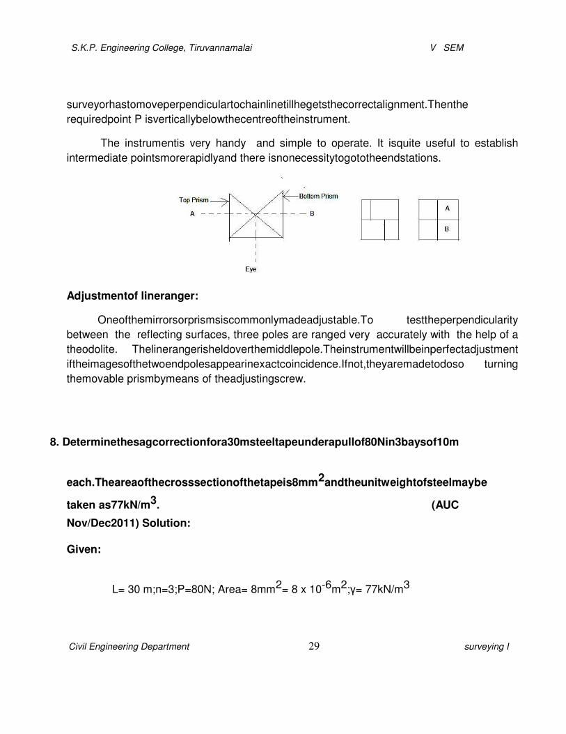
Itisasimpleinstrumentusedforfixingintermediatepointsonchainline.Inthisinstrument two
right-angledisoscelestriangularprisms areplaced one abovetheother.
Inordertoestablishapointinbetween theendstationsA andB thesurveyorholds the
instrumentattheleveloftheeyeandstandsapproximately inlinenearP.Raysoflight fromA
passesthroughtheupperprism getreflectedappearsto theeyeperpendiculartoAB.Similarly
anotherrayfromBreachestheeyeafterreflection.ThattheimagesofrangingrodsatstationA
andBappearinupperandlowerprismdirectly infrontofthesupervisor.Ifthealignmentiscorrect
boththeimagesappear oneabovetheotherina verticalline otherwise get separated.The
S.K.P. Engineering College, Tiruvannamalai V SEM
Civil Engineering Department 29 surveying I
surveyorhastomoveperpendiculartochainlinetillhegetsthecorrectalignment.Thenthe
requiredpoint P isverticallybelowthecentreoftheinstrument.
The instrumentis very handy and simple to operate. It isquite useful to establish
intermediate pointsmorerapidlyand there isnonecessitytogototheendstations.
Adjustmentof lineranger:
Oneofthemirrorsorprismsiscommonlymadeadjustable.To testtheperpendicularity
between the reflecting surfaces, three poles are ranged very accurately with the help of a
theodolite. Thelinerangerisheldoverthemiddlepole.Theinstrumentwillbeinperfectadjustment
iftheimagesofthetwoendpolesappearinexactcoincidence.Ifnot,theyaremadetodoso turning
themovable prismbymeans of theadjustingscrew.
8. Determinethesagcorrectionfora30msteeltapeunderapullof80Nin3baysof10m
each.Theareaofthecrosssectionofthetapeis8mm2andtheunitweightofsteelmaybe
taken as77kN/m3. (AUC
Nov/Dec2011) Solution:
Given:
L= 30 m;n=3;P=80N; Area= 8mm2= 8 x 10⁻⁶m2;γ= 77kN/m3

S.K.P. Engineering College, Tiruvannamalai V SEM
Civil Engineering Department 30 surveying I
Totalweightof tape = 77x103x8 x 10-6x10=6.16N
Cs=
LW2
24n2P
2
10X�6.16�2
=
24X�1�2X�80
�2
=0.00247 m
Cs=3x0.00247=0.00741m
True length= 30–0.00741
True length=29.993m
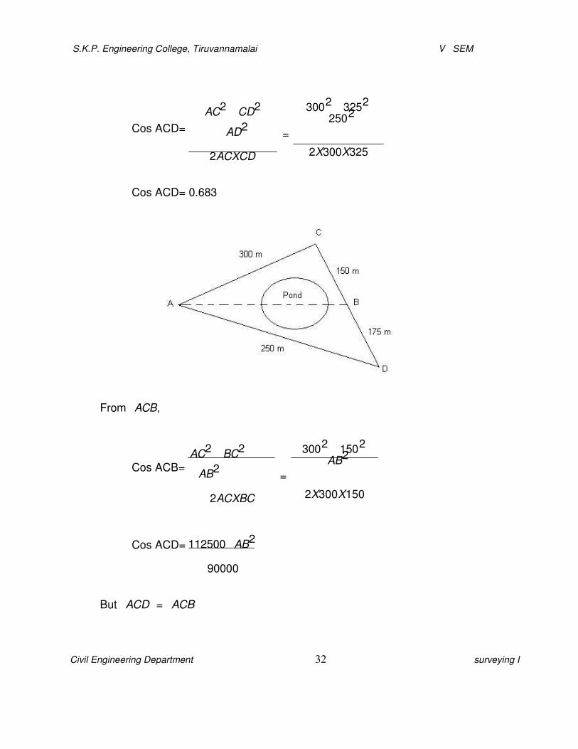
9. A andBaretwopoints ontheoppositesides ofapond.ThesurveyorestablishesalineAC
clearofthepondsuchthatB isvisible fromC.heestablishes anotherpointDonthe line CB
producedsothatthelineADisalsoclearofthepond.IfthedistancesAC,CB,BDandDA
are300m, 150 m,175mand250mrespectively.DeterminethedistanceAB.
(AUC Nov/Dec2011)

S.K.P. Engineering College, Tiruvannamalai V SEM
Civil Engineering Department 31 surveying I
CD= CB + BD = 150+175= 325m
Applyingcosineformulae,�ACD
S.K.P. Engineering College, Tiruvannamalai V SEM
Civil Engineering Department 32 surveying I
Cos ACD=
AC2 �CD2
�AD2
2ACXCD
3002 �3252
�2502
=
2X300X325
Cos ACD= 0.683
From�ACB,
Cos ACB=
Cos ACD=
AC2 �BC2
�AB2
2ACXBC
112500�AB2
90000
3002 �1502
�AB2
=
2X300X150
But�ACD
=�ACB

S.K.P. Engineering College, Tiruvannamalai V SEM
Civil Engineering Department 33 surveying I
112500�AB2
0.683=
90000
AB2=51030
AB =225.89m
Thewidth of theriver,AB =225.89m
10.Explainthemeasurementoflengthwiththehelpofatape. (AUC Nov/Dec2010)
For accuratemeasurements thelengthsarenowmeasuredwith tapeand notwith
achain. Thefollowingprocedure isadopted.
�Letthelengthofa lineAB be measured, pointAbeing thestartingpoint.Placea ranging rod
behind thepointBsothatit isonthelinewith respect tothestartingpoint A.
�Thefollowerstands atthe pointA holdingone end ofthetape while theleadermoves ahead
holdingzeroendofthe tapeinonehandabundleofarrowsintheother.Whenhe reaches
approximatelyonetapelengthdistantfromA,the followerdirectshimforrangingintheline.
The tapeisthenpulledoutandwhippedgently tomakesure thatitsentirelengthliesalong
theline. Theleaderthenpushesthearrow intothe ground,oppositetozero. Thepinis
usuallyinclinedfromverticalabout20or30degrees,startingatrightanglestothelineso that
itsidesunder thetape,with its centre oppositethegraduationpointon thetape.
�Thefollowerthenreleaseshisendof thetape andthe twomoves forward alongtheline, the
leaderdraggingthetape.Whentheendofthetapereachesthearrowjustplaced,follower

S.K.P. Engineering College, Tiruvannamalai V SEM
Civil Engineering Department 34 surveying I
callsout“tape”.Hethenpicksuptheendofthetapeandlinestheleaderinandthe
procedureisrepeatedasin step2.
�Whenthesecondarrowhasbeenestablishedby theleader,the followerpicksupthe first
arrow andboth thepersonsmoveaheadasdescribedinstep3. Theprocedureis repeated
untiltentapelengthshavebeenmeasured.thesurveyorrecordsthetransferofarrowsin
thefield book.
�Attheendoftheline,atB,thelastmeasurementwill generallybeapartialtapelength from
thelastarrow setto theendpointofthe line. The leaderholds theendofthetapeatBwhile
thefollowerpulls the tape back till itbecomestautandthenreadsagainstthearrow.
11.Explainthetraversingand plotting procedures of chainsurvey. (AUC May/June
2013) Traversing:
Traverseisamethodin thefield ofsurveying toestablish control networks. Traverse
networks involve placingsurveystations alongalineorpathoftravel,and then using the
previously surveyedpointsas abaseforobserving thenext point.
The methodin which thewhole workisdone with chain andtape iscalledchain
traversing. No anglemeasurement isused
andthedirectionsofthelinesarefixedentirelybylinear
measurementsAnglesfixedbylinearortiemeasurementsareknown aschain angles. The
method isunsuitableforaccurateworkand isgenerallyused ifananglemeasuring
instrumentsuchasa compass,sextantor theodolite is available.
Proceduresofchain survey:
Thechaintraversingis tofindouttheareaoftheoneblock bytraversingwith thechain. The
instrumentsused are Chain,Arrows, CrossStaff,Rangingrod, Pegsandhammer.
Thesteeltape istakenandtwo partiesaremade. Onepartystandsatthepointfromwhere

S.K.P. Engineering College, Tiruvannamalai V SEM
Civil Engineering Department 35 surveying I
measurementisstartedand theotherpartygoestothepoint until which
measurementisrequired.
Chainingisdoneoffsetiscarriedoutatthecornerandatthesteps,usingacrossstuff.The
diagonalisalsomeasuredfor checkingpurposes.Theobservation ismadeandthedistance
observedis recorded, inthiswaywhole ofthebuildingismeasuredandeach length
isrecordedin thecopy.Then somescale is chosentorepresent thesemeasurementson
thefield bookand it is drawn on thefield booklikea plan.

S.K.P. Engineering College, Tiruvannamalai V SEM
Civil Engineering Department 36 surveying I
Eachsideofthelengthcanbecalculatedand plinthareaof thebuildingiscalculatedby
using theabovefigure.
PlinthArea= ½(abxad) + ½ (bcxcd) + ½ (hgxhe) +½(texty)
Thebuildingcanbe divided into number of sections
andeachareaofthesectionis calculatedand added.
12.Explainthe fieldand officeworkin chain surveying? (AUC May/June 2013)
FieldandOfficework:
Thepracticeof surveyingactuallyboilsdown tofieldworkandoffice work. The
FIELDWORKconsistsoftaking measurements,collectingengineering data,andtesting
materials. TheOFFICEWORK includes taking careofthe computationanddrawing
thenecessary information forthepurposeofthesurvey.
FieldWork:
Field workisof primary importancein all typesofsurveys. Tobea skilledsurveyor,you
must spenda certainamountof timein thefield to acquire neededexperience. The
studyofthis trainingmanual will enable you to
S.K.P. Engineering College, Tiruvannamalai V SEM
Civil Engineering Department 37 surveying I
understandtheunderlyingtheoryofsurveying,theinstruments and their uses,andthe
surveying methods.However,a high degreeofproficiency in actual surveying,as
inotherprofessions, depends largelyupon theduration,extent, and variationofyour actual
experience.
Youshould develop thehabitofSTUDYING theproblem
thoroughlybeforegoingintothe field, youshouldknowexactlywhatis tobedone;how youwill
doit;why youprefera certain approachoverotherpossible
solutions;andwhatinstrumentsandmaterialsyouwill need to accomplishtheproject.It
isessential thatyoudevelopSPEED and CONSISTENTACCURACY in all your fieldwork.
Thismeans thatyouwill needpracticein handling theinstruments, taking observations
andkeepingfield notes, and planning systematicmoves.
It isimportant thatyoualso develop thehabitofCORRECTNESS.Youshould
notaccept anymeasurement ascorrect withoutverification.Verification,
asmuchaspossible,should be different from theoriginal method usedinmeasurement.
Theprecisionof measurement must be consistent with
theacceptedstandardforaparticularpurposeof thesurvey.Fieldworkalso includes adjusting
theinstrumentsandcaringfor field equipment.Donot attempt toadjust any instrument unless
youunderstandtheworkingsorfunctionsofitsparts.Adjustmentofinstruments in
theearlystagesofyourcareer requiresclose supervision fromasenior EA.
OfficeWork:
Officeworkin surveyingconsistsof converting thefieldmeasurements intoa
usableformat. Theconversion ofcomputed, oftenmathematical,values
mayberequiredimmediatelyto continue

S.K.P. Engineering College, Tiruvannamalai V SEM
Civil Engineering Department 38 surveying I
thework, or it maybedelayeduntil a series of field measurements
iscompleted.Althoughthese operationsare performed in thefield duringlapsesbetween
measurements, theycanalsobe consideredoffice work.Suchoperationsare normallydone to
savetime. Special equipment, such
as calculators, conversion tables, andsomedraftingequipmentisusedinmost office work.
Inoffice work, convertingfieldmeasurements(alsocalled reducing)involves
theprocessofcomputing, adjusting,andapplyingastandardrule to numerical values.
13.Explainhowyouwillconductchain surveyto measurealandparcelin agriculture field.
(CO1-H1-AUC May/June 2013)
Usingchainingandrangingthedistancebetweentwopointscanbemeasured.The
instrumentsrequired arechain, arrows,ranging rods,pegsandhammers.
Procedures:
Firstmarkastraightlineofastandardlengthonaflatfirmground.ThetwoendpointsAandBare
selectedonasurveylinewhichistobemeasured. A rangingrodiserectedatthepointB,while
thesurveyorstandswithanotherrodatpointA. A rodisestablishedatapointinlinewithABata
distancenotgreaterthanonechainlengthfromA. ThesurveyoratA thensignalstheassistantto
movetransversetothechainlinetillheislinewithAandB.Similarlyotherintermediatepointscan
beestablished.Thenbyusingchain,thedistanceismeasured.Tofindthepacinglength,we
shouldwalkalongthechainlineanditisfoundfrompacinglength.
Pacinglength=Distancebetweenthepoints/Noofsteps
Thedistancebetweentwo points= (Noofarrowx Nominal length+Fractional
length)m
S.K.P. Engineering College, Tiruvannamalai V SEM
Civil Engineering Department 39 surveying I
Thedistancebetween two pointscanbecalculatedand alsosame procedure
isusedtofind theother sideof theline.Thefinally land parcel of agriculturalfield ismeasured.
Precautions:
�Surfaceshould besmooth and even.
�Surveyormust walkin straightline.
�Measuringtapemust bekeptstraightandhorizontal.
�Rangingshouldbeperformedformeasurementsgreaterthantapelength.
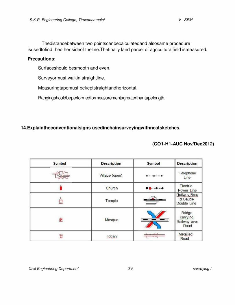
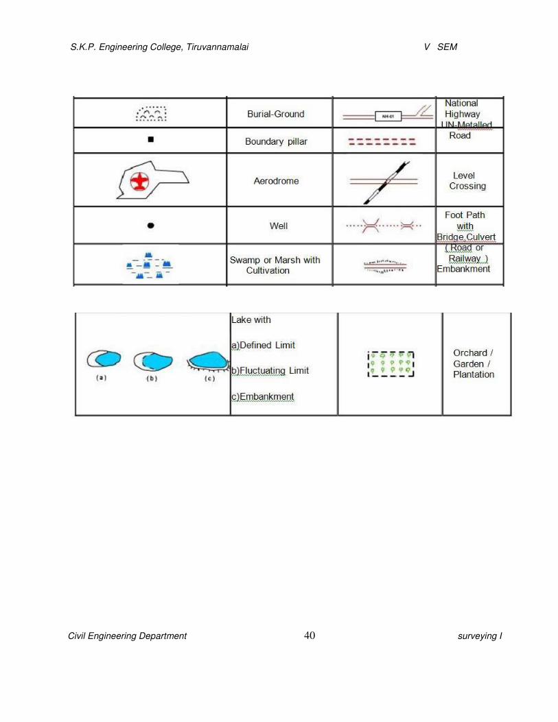
14.Explaintheconventionalsigns usedinchainsurveyingwithneatsketches.
(CO1-H1-AUC Nov/Dec2012)
S.K.P. Engineering College, Tiruvannamalai V SEM
Civil Engineering Department 40 surveying I

S.K.P. Engineering College, Tiruvannamalai V SEM
Civil Engineering Department 41 surveying I
15.Alinewasmeasured withasteeltape which wasexactly30mat25oCandatapullof15kg, the
temperature during the measurement was 35oC and the pull applied was 25 kg.
Assumingthetape tobesupportedatevery30m,calculatethe truelength,ifthecross
sectionalareaofthetape was0.020cm2,coefficientofthermalexpansionofthematerialper
oC=3 x10⁻⁶,modulesofelasticity(E)=2.1x 10⁶kg/cm2andweight of tapematerial =0.8kg.
(CO1-H1-AUC Nov/Dec2012)

S.K.P. Engineering College, Tiruvannamalai V SEM
Civil Engineering Department 42 surveying I
Solution:
Given:
L=30m;T0= 25oC;Tm= 35oC;Po=15kg;P=25kg;Area=0.020cm2;
W= 0.8kg;α= 3 x 10⁻⁶;E=2.1 x 10⁶kg /cm2
i) CorrectionforTemperature:
Ct=α (Tm-T0)L
=3x10⁻⁶(35–25)x30
Ct= 0.0009m
iii)CorrectionforPull:
CP=
�P�Po�
L AE �25�15�X30
=
0.02X2.1X106
CP=0.00714m
iv)Sag Correction:
LW2
30X�0.8�2
Cs=
24n2P
2
=
24X�1�2X�25�
2
Cs= 0.00128m

S.K.P. Engineering College, Tiruvannamalai V SEM
Civil Engineering Department 43 surveying I
Total correction=Ct+CP- Cs
= 0.0009+0.00714–0.00128
Total correction=0.00676
m
Truelength=Length+correction
= 20+ 0.00676
Truelength = 20.00676 m
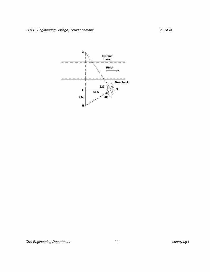
16.Asurveyline EFGcrosses ariver,FandG being onthe nearanddistancebanks
respectively.StandingatS, a point60mmeasured perpendicularlyto EF fromF,the
bearings of G and Eare 325oand 230orespectively.EF being30m.Findthewidthofthe
river. (AUC
May/June 2012)
S.K.P. Engineering College, Tiruvannamalai V SEM
Civil Engineering Department 44 surveying I
S.K.P. Engineering College, Tiruvannamalai V SEM
Civil Engineering Department 45 surveying I
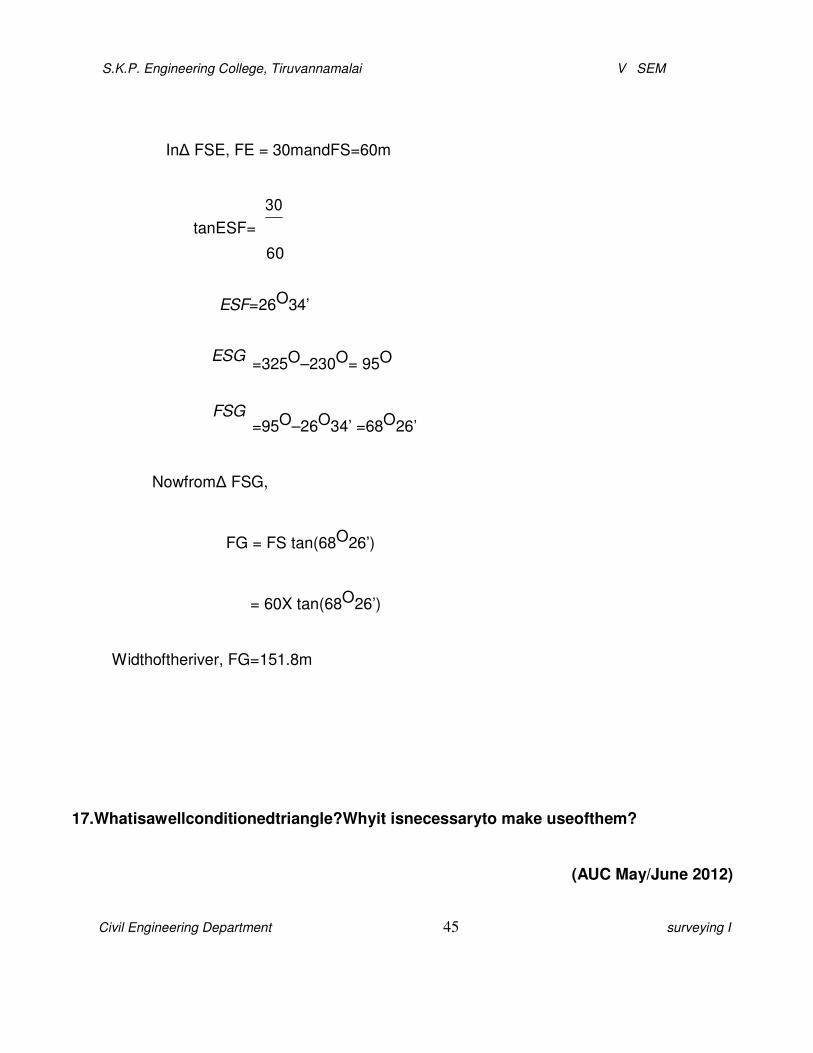
InΔ FSE, FE = 30mandFS=60m
30
tanESF=
60
�ESF=26O34’
�ESG
�FSG
=325O–230O= 95O
=95O–26O34’ =68O26’
NowfromΔ FSG,
FG = FS tan(68O26’)
= 60X tan(68O26’)
Widthoftheriver, FG=151.8m
17.Whatisawellconditionedtriangle?Whyit isnecessaryto make useofthem?
(AUC May/June 2012)

S.K.P. Engineering College, Tiruvannamalai V SEM
Civil Engineering Department 46 surveying I
All well-conditioned triangle is onein which noincludedangle islessthan 30’ or
greater than 120’. Anequilateraltriangle isthebestconditioned triangleoranideal triangle.
Other examples ofwell-conditionedtrianglesareshown infigure.
Well-conditioned trianglesarerecommended because of their apexpointswhich
are verysharp and canbelocatedaccurately.Intheuseofwell-conditioned triangles, there is
no possibilityofrelative displacement oftheplottedpoint.Triangleswhich have
includedangles less than30’ andmorethan120’ arecalledasill-conditionedtriangles.

S.K.P. Engineering College, Tiruvannamalai V SEM
Civil Engineering Department 47 surveying I
Thesetrianglesarenotpreferredin chain surveyingor triangulationsurveyas their apex
pointsarenot sharp andwell defined.Ifin certainfield conditionsiftheyare unavoidable
greatcare must betakenin chainingand plotting.
18.Explainthemethodsofdirect rangingindetail.(AUC Nov/Dec2009)
Whenintermediaterangingrodsare fixedonastraightlineby directobservation fromend
stations,theprocessisknownasdirectranging.Directrangingispossiblewhentheendstations
areintervisible.
AssumethatAandBtwoendstationsofchainline,wheretworangingrodsarealready
fixed.Supposeitis requiredto fixarangingrodattheintermediatepointPonthechainlineinsuch
awaythatthepointsA,P&Bareinsamestraightline. Thesurveyorstandsabout twometers
behindtherangingrod atAbylookingtowardslineAB.TheassistantholdsrangingrodatP
verticallyatarm’slengththerodshouldbeheldtightlybythethumbandforefinger.Nowthe
surveyordirecttheassistantto movetherangingrodtotheleftorrightuntil thethreerangingrods
comeexactly thesamestraightline.Therangingwillbeperfect,whenthethreerangingrods
coincideandappearasasinglerod. Whenthesurveyorissatisfiedthattherangingisprefect,he
signalstheassistanttofixtherangingrodontheground.Byfollowingthesameprocedure,the other
ranging rodsmaybefixedontheline.

S.K.P. Engineering College, Tiruvannamalai V SEM
Civil Engineering Department 48 surveying I
19.Explainthemethodofreciprocal ranging in detail.(AUC Nov/Dec2010)(AUC Nov/Dec2009)
Indirectrangingisusedwhentheendstationsarenotintervisibleduetohighgroundora
hilloriftheendsaretoolong.Insuchcases,intermediatepointscanbe fixedonthesurveylineby a
processknown asreciprocal ranging.
Thevisionrangingandlinerangercan beadoptedonlywhentheendstationsareinter-
visible.However,inmany reallifesituations,thelineofsightbetweentwostationsisobstructedby
naturalor man-made objects (Figure),or theybeingtoo faraparttobe clearlyvisible.Undersuch
conditions,indirectorreciprocal rangingis resorted to.In this method,twointermediatepointsC1
andD1areselectedwhicharenotalongtheline ofsightAB(surveyline).StationsC1andD1are
approximately inlinesuchthatlineC1D1isapproximately paralleledtoAB.C1issosituatedthat
both D1andB are visiblefrom it, while from D1 bothA andC1canbesighted.

S.K.P. Engineering College, Tiruvannamalai V SEM
Civil Engineering Department 49 surveying I
ThesurveyorsaresituatedatC1andD1originally.SurveyoratC1directssurveyoratD1
tomovesuchthatheisalignedindirectionC1Btooccupynew positionatD2.NextsurveyoratD2
directs thesurveyoratC1toalignalongline AD2tooccupy new positionC2.Thisprocessof
alignmentandrealignmentcontinuestillboththesurveyorsoccupypositionsCandDwhichare
situatedalong lineAB ensuring that surveylineisaligned alongACDB as shown inFigure.
20.Whatareoffsets?Howaretheytakenandrecorded?Plotthefollowingcrossstaffsurvey and
calculatethearea

S.K.P. Engineering College, Tiruvannamalai V SEM
Civil Engineering Department 50 surveying I
Solution:

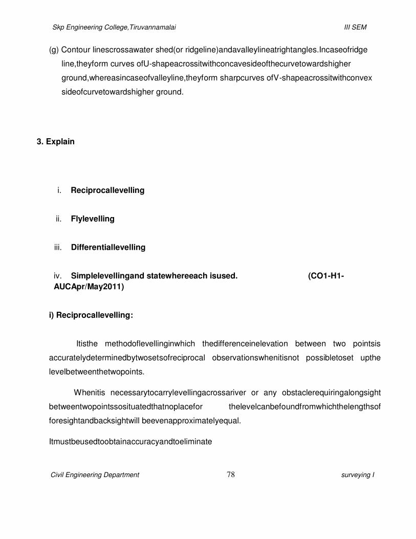
Skp Engineering College,Tiruvannamalai III SEM
Civil Engineering Department 51 surveying I
Area1=
Area2=
x30x 36= 540m2
2
1 x30x30=450 m2
2
Area3=18x30=540m2
1
Area4= x18x15= 135m2
2
Area5=42x36 =1512m2
1
Area6=
Area7=
Area8=
x42x12= 252m2
2
1x24x48= 576m2
2
1x48x 45= 1080 m2
2
Total area=540+ 450+540+ 135+1512+ 252+576+ 1080
Total area= 5085m2

Skp Engineering College,Tiruvannamalai III SEM
Civil Engineering Department 52 surveying I
21.The followingcrossstaffsurveyand calculatethe area.
D
E 100
F120
370
270
240
125
100
125 C
90 B
A
Solution:

Skp Engineering College,Tiruvannamalai III SEM
Civil Engineering Department 53 surveying I

Skp Engineering College,Tiruvannamalai III SEM
Civil Engineering Department 54 surveying I
Area1=
Area2=
x125 x 120 = 7500m2
2
1 x100 x 90= 4500 m2
2
Area3= 140x90= 12600m2
1
Area4=
Area5=
x140 x 35=2450 m2
2
1x130 x 125 = 8125m2
2
Area6= 145x100 = 14500 m2
1
Area7=
Area8=
x145 x 20= 1450m2
2
1x100 x 100 = 5000 m2
2

Skp Engineering College,Tiruvannamalai III SEM
Civil Engineering Department 55 surveying I
Total
area=7500 +
4500+12600+
2450 +
8125+14500+
1450 + 5000
Totalar
ea=
56125
m2

Civil Engineering Department 52 Surveying I
UNIT 2
COMPASS AND PLANE TABLE SURVEYING
PART A
1. Define: Compass surveying. What are the objects of compass surveying?
(CO1-L1-AUC MAY/JUN 2013)
Compass surveying is the type of surveying in which the direction
of the survey lines are measured with a compass and the length of the
survey lines are measured with a tape or chain in the field.
2. Write the names of the instruments used in chain surveying.
(i). Instruments for the direct measurement of directions:
1. Surveyor’s compass.
2. Prismatic compass.
(ii).Instruments for the measurement of angles:
1. Sextant.
2. Theodolite.
3. Define: (a). True meridian
and bearing. True meridian:
(CO1-L1-AUC MAY/JUN 2013)

Skp Engineering College,Tiruvannamalai III SEM
Civil Engineering Department 54 surveying I
Skp Engineering College,Tiruvannamalai III SEM
Civil Engineering Department 55 surveying I
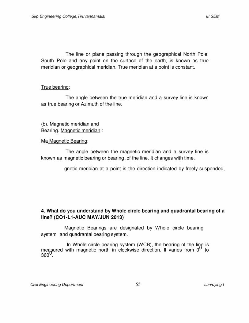
The line or plane passing through the geographical North Pole,
South Pole and any point on the surface of the earth, is known as true
meridian or geographical meridian. True meridian at a point is constant.
True bearing:
The angle between the true meridian and a survey line is known
as true bearing or Azimuth of the line.
(b). Magnetic meridian and
Bearing. Magnetic meridian :
Ma Magnetic Bearing:
The angle between the magnetic meridian and a survey line is
known as magnetic bearing or bearing .of the line. It changes with time.
gnetic meridian at a point is the direction indicated by freely suspended,
4. What do you understand by Whole circle bearing and quadrantal bearing of a
line? (CO1-L1-AUC MAY/JUN 2013)
Magnetic Bearings are designated by Whole circle bearing
system and quadrantal bearing system.
In Whole circle bearing system (WCB), the bearing of the line is measured with magnetic north in clockwise direction. It varies from 00 to 3600.
Skp Engineering College,Tiruvannamalai III SEM
Civil Engineering Department 56 surveying I
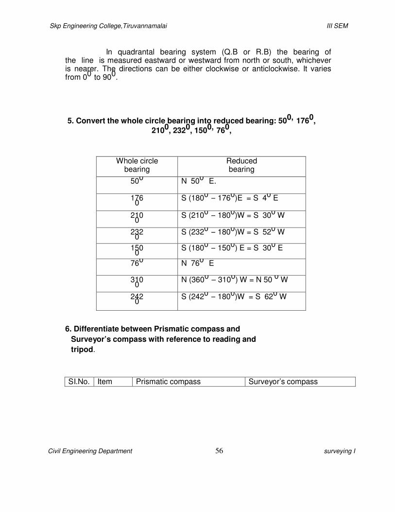
In quadrantal bearing system (Q.B or R.B) the bearing of the line is measured eastward or westward from north or south, whichever is nearer. The directions can be either clockwise or anticlockwise. It varies from 00 to 900.
5. Convert the whole circle bearing into reduced bearing: 500, 1760,
2100, 2320, 1500, 760,
Whole circle bearing
Reduced bearing
500 N 500 E.
1760
S (1800 – 1760)E = S 40 E
2100
S (2100 – 1800)W = S 300 W
2320
S (2320 – 1800)W = S 520 W
1500
S (1800 – 1500) E = S 300 E
760 N 760 E
3100
N (3600 – 3100) W = N 50 0 W
2420
S (2420 – 1800)W = S 620 W
6. Differentiate between Prismatic compass and
Surveyor’s compass with reference to reading and
tripod.
SI.No. Item Prismatic compass Surveyor’s compass

Skp Engineering College,Tiruvannamalai III SEM
Civil Engineering Department 57 surveying I
1. Reading (i). The reading is taken with a help of prism provided at the eye
slit.
(ii). Sighting and reading
taking can be done
(i). The reading is taken by directly seeing through the top of
the glass.
(ii). Sighting and reading
taking cannot be done 2. Tripod Tripod may or may not be
provided.
The instrument cannot be used
without a tripod.
7. The fore bearing of a line PQ is N 280 W. What is its back bearing? (CO1-L1-
AUC MAY/JUN 2013)
In quadrantal bearing (RB) system, the FB and BB are
numerically equal but the quadrants are just opposite.
The FB of a line PQ is N 280
W, Then its BB is S 280 E .
8. Define: Fore and Back bearing.
The bearing of a line is measured in the direction of the
progress of the survey is called the fore bearing of the (FB) line.
The bearing of a line is measured in the direction opposite to the survey is called the back bearing of the (BB) line.
BB = FB + 180 0 . (FB greater than 180 0, use - sign) (FB smaller than 180 0, use + sign)
Skp Engineering College,Tiruvannamalai III SEM
Civil Engineering Department 58 surveying I
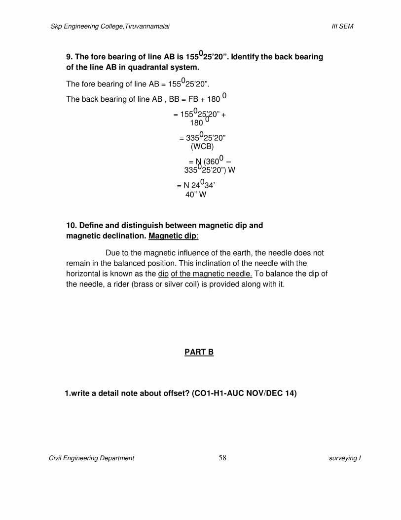
9. The fore bearing of line AB is 155025’20”. Identify the back bearing
of the line AB in quadrantal system.
The fore bearing of line AB = 155025’20”.
The back bearing of line AB , BB = FB + 180 0
= 155025’20” + 180 0
= 335025’20” (WCB)
= N (3600 – 335025’20”) W
= N 24034’ 40’’ W
10. Define and distinguish between magnetic dip and
magnetic declination. Magnetic dip:
Due to the magnetic influence of the earth, the needle does not
remain in the balanced position. This inclination of the needle with the
horizontal is known as the dip of the magnetic needle. To balance the dip of
the needle, a rider (brass or silver coil) is provided along with it.
PART B
1.write a detail note about offset? (CO1-H1-AUC NOV/DEC 14)

Skp Engineering College,Tiruvannamalai III SEM
Civil Engineering Department 59 surveying I
These are the lateral measurements from the base line to fix the positions of the
different objects of the work with respect to base line. These are generally set at right
angle offsets. It can also be drawn with the help of a tape. There are two kinds of
offsets:
1) Perpendicular offsets,
and
2)Oblique offsets.
The measurements are taken at right angle to the survey line called perpendicular or right angled offsets.
The measurements which are not made at right angles to the survey line are called
oblique offsets or tie line offsets.
Procedure in chain survey:
The preliminary inspection of the area to be surveyed is called reconnaissance. The surveyor inspects the area to be surveyed, survey or prepares index sketch or key plan.
2.Marking Station:
Surveyor fixes up the required no stations at places from where maximum possible stations are possible.
3. Then he selects the way for passing the main line, which should be horizontal and
clean as possible and should pass approximately through the centre of work.
4. Then ranging roads are fixed on the
stations.
5. After fixing the stations, chaining could be
started.
6. Make ranging wherever
necessary.
Skp Engineering College,Tiruvannamalai III SEM
Civil Engineering Department 60 surveying I
7. Measure the change and
offset.
8. Enter in the field the book
2. write a Classification Of Surveying? (CO1-H1-AUC NOV/DEC 14)
Generally, surveying is divided into two major categories: plane and geodetic
surveying.
PLANE SURVEYING
PLANE SURVEYING is a process of surveying in which the portion of the
earth being surveyed is considered a plane. The term is used to designate survey
work in which the distances or areas involved are small enough that the curvature of
the earth can be disregarded without significant error. In general, the term of
limited extent. For small areas, precise results may be obtained with plane surveying
methods, but the accuracy and precision of such results will decrease as the area
surveyed increases in size. To make computations in plane surveying, you will use
formulas of plane trigonometry, algebra, and analytical geometry.
A great number of surveys are of the plane surveying type. Surveys for the
location and construction of highways and roads, canals, landing fields, and railroads
are classified under plane surveying. When it is realized that an arc of 10 mi is only
0.04 greater that its subtended chord; that a plane surface tangent to the spherical arc
has departed only about 8 in. at 1 mi from the point of tangency; and that the sum of
the angles of a spherical triangle is only 1 sec greater than the sum of the angles
of a plane triangle for a triangle having an area of approximately 75 sq mi on the
earth’s surface, it is just reasonable that the errors caused by the earth’s curvature be
considered only in precise surveys of large areas.
In this training manual, we will discuss primarily the methods used in plane
surveying rather than those used in geodetic surveying.
GEODETIC SURVEYING
GEODETIC SURVEYING is a process of surveying in which the shape and size of the
earth are considered. This type of survey is suited for large areas and long lines and
Skp Engineering College,Tiruvannamalai III SEM
Civil Engineering Department 61 surveying I
is used to find the precise location of basic points needed for establishing control
for other surveys. In geodetic surveys, the stations are normally long distances apart,
and more precise instruments and surveying methods are required for this type of
surveying than for plane surveying.
the surface of the earth are not along straight lines or planes, but on a curved surface.
Hence, in the computation of distances in geodetic surveys, allowances are made
for the earth’s minor and major diameters from which a spheroid of reference is
developed. The position of each geodetic station is related to this spheroid. The
positions are expressed as latitudes (angles north or south of the Equator) and
longitudes (angles east or west of a prime meridian) or as northings and castings on a
rectangular grid.
The methods used in geodetic surveying are beyond the scope of this training manual
TOPOGRAPHIC SURVEYS
The purpose of a TOPOGRAPHIC SURVEY is to gather survey data about the natural
and man-made features of the land, as well as its elevations. From this
information a three- dimensional map may be prepared. You may prepare the
topographic map in the office after collecting the field data or prepare it right away in
the field by plane table. The work usually consists of the following:
1. Establishing horizontal and vertical control that will serve as the framework of the
survey
2. Determining enough horizontal location and elevation (usually called side shots) of ground points to provide enough data for plotting when the map is prepared
3. Locating natural and man-made features that may be required by the purpose of
the survey
4. Computing distances, angles, and
elevations
5. Drawing the topographic map
Topographic surveys are commonly identified with horizontal and/or vertical control of
third- and lower-order accuracies.

Skp Engineering College,Tiruvannamalai III SEM
Civil Engineering Department 62 surveying I
ROUTE SURVEYS
The term route survey refers to surveys necessary for the location and construction of
lines of transportation or communication that continue across country for some
distance, such as highways, railroads, open-conduit systems, pipelines, and power
lines. Generally, the preliminary survey for this work takes the form of a topographic
survey. In the final stage, the work may consist of the following:
1. Locating the center line, usually marked by stakes at 100-ft intervals called
stations
2. Determining elevations along and across the center line for plotting profile and cross sections
3. Plotting the profile and cross sections and fixing the
grades
4. Computing the volumes of earthwork and preparing a mass
diagram
5. Staking out the extremities for cuts and
fills
6. Determining drainage areas to be used in the design of ditches and
culverts
7. Laying out structures, such as bridges and
culverts
8. Locating right-of-way boundaries, as well as staking out fence lines, if
necessary
SPECIAL SURVEYS
As mentioned earlier in this chapter, SPECIAL SURVEYS are conducted for a
specific purpose and with a special type of surveying equipment and methods. A brief
discussion of some of the special surveys familiar to you follows.
Skp Engineering College,Tiruvannamalai III SEM
Civil Engineering Department 63 surveying I
Land Surveys
LAND SURVEYS (sometimes called cadastral or property surveys) are
conducted to establish the exact location, boundaries, or subdivision of a tract of land
in any specified area. This type of survey requires professional registration in all
states. Presently, land surveys generally consist of the following chores:
1. Establishing markers or monuments to define and thereby preserve the boundaries of land belonging to a private concern, a corporation, or the government.
2. Relocating markers or monuments legally established by original surveys. This
requires examining previous survey records and retracing what was done. When
some markers or monuments are missing, they are reestablished following recognized
procedures, using whatever information is available.
3. Rerunning old land survey lines to determine their lengths and directions. As a result of the high cost of land, old lines are remeasured to get more precise measurements.
4. Subdividing landed estates into parcels of predetermined sizes and
shapes.
5. Calculating areas, distances, and directions and preparing the land map to
portray the survey data so that it can be used as a permanent record. 6. Writing a
technical description for deeds.
Control Surveys
CONTROL SURVEYS provide "basic control" or horizontal and vertical positions of
points to which supplementary surveys are adjusted. These types of surveys
(sometimes termed and traverse stations and the elevations of bench marks. These
control points are further used as References for hydrographic surveys of the coastal
waters; for topographic control; and for the control of many state, city, and private
surveys.
Horizontal and vertical controls generated by land (geodetic) surveys provide
coordinated position data for all surveyors. It is therefore necessary that these types of
surveys use first- order and second-order accuracies.

Skp Engineering College,Tiruvannamalai III SEM
Civil Engineering Department 64 surveying I
Hydrographic
Surveys
HYDROGRAPHIC SURVEYS are made to acquire data required to chart and/or map
shorelines and bottom depths of streams, rivers, lakes, reservoirs, and other larger
bodies of water. This type of survey is also of general importance to navigation and to
development of water resources for flood control, irrigation, electrical power, and water
supply.
As in other special surveys, several different types of electronic and radio-acoustical
instruments are used in hydrographic surveys. These special devices are commonly
used in determining water depths and location of objects on the bottom by a
method called taking SOUNDINGS. Soundings are taken by measuring the time
required for sound to travel downward and be reflected back to a receiver aboard a
vessel.
4.give the types of surveying? (CO1-H1-AUC NOV/DEC 14)
The practice of surveying actually boils down to fieldwork and office work. The
FIELDWORK consists of taking measurements, collecting engineering data, and
testing materials. The OFFICE WORK includes taking care of the computation and
drawing the necessary information for the purpose of the survey.
FIELDWORK
FIELDWORK is of primary importance in all types of surveys. To be a skilled surveyor,
you must spend a certain amount of time in the field to acquire needed experience.
The study of this training manual will enable you to understand the underlying theory
of surveying, the instruments and their uses, and the surveying methods. However, a
high degree of proficiency in actual surveying, as in other professions, depends largely
upon the duration, extent, and variation of your actual experience.
You should develop the habit of STUDYING the problem thoroughly before going into
the field, You should know exactly what is to be done; how you will do it; why you
Skp Engineering College,Tiruvannamalai III SEM
Civil Engineering Department 65 surveying I
prefer a certain approach over other possible solutions; and what instruments and
materials you will need to accomplish the project.
It is essential that you develop SPEED and CONSISTENT ACCURACY in all
your fieldwork. This means that you will need practice in handling the instruments,
taking observations and keeping field notes, and planning systematic moves.
It is important that you also develop the habit of CORRECTNESS. You should not
accept any measurement as correct without verification. Verification, as much as
possible, should be different from the original method used in measurement. The
precision of measurement must be consistent with the accepted standard for a
particular purpose of the survey.
Fieldwork also includes adjusting the instruments and caring for field equipment. Do
not attempt to adjust any instrument unless you understand the workings or functions
of its parts. Adjustment of instruments in the early stages of your career requires close
supervision from a senior EA.
Factors Affecting
Fieldwork
The surveyor must constantly be alert to the different conditions encountered in the
field. Physical factors, such as TERRAIN AND WEATHER CONDITIONS, affect
each field survey in varying degrees. Measurements using telescopes can be
stopped by fog or mist. Swamps and flood plains under high water can impede taping
surveys. Sights over open water or fields of flat, unbroken terrain create ambiguities in
measurements using microwave equipment. The lengths of light-wave distance in
measurements are reduced in bright
sunlight. Generally, reconnaissance will predetermine the conditions and alert the survey party to the best method to use and the rate of progress to expect.
The STATE OF PERSONNEL TECHNICAL READINESS is another factor affecting
field- work. As you gain experience in handling various surveying instruments, you
can shorten survey time and avoid errors that would require resurvey.

Skp Engineering College,Tiruvannamalai III SEM
Civil Engineering Department 66 surveying I
The PURPOSE AND TYPE OF SURVEY are primary factors in determining the
accuracy requirements. First-order triangulation, which becomes the basis or
"control" of future surveys, is made to high-accuracy standards. At the other
extreme, cuts and fills for a highway survey carry accuracy standards of a much
lower degree. In some construction surveys, normally inaccessible distances must
be computed. The distance is computed by means of trigonometry, using the
angles and the one distance that can be measured. The measurements must be
made to a high degree of precision to maintain accuracy in the computed
distance.
So, then, the purpose of the survey determines the accuracy requirements. The
required accuracy, in turn, influences the selection of instruments and procedures. For
instance, comparatively rough procedures can be used in measuring for earthmoving,
but grade and alignment of a highway have to be much more precise, and they,
therefore, require more accurate measurements. Each increase in precision also
increases the time required to make the measurement, since greater care and more
observations will be taken. Each survey measurement will be in error to the extent that
no measurement is ever exact. The errors are classified as systematic and accidental
and are explained in the latter part of this text. Besides errors, survey measurements
are subject to mistakes or blunders. These arise from misunderstanding of the
problem, poor judgment, confusion on the part of the surveyor, or simply from an
oversight. By working out a systematic procedure, the surveyor will often detect a
mistake when some operation seems out of place. The procedure will be an
advantage in setting up the equipment, in making observations, in recording field
notes, and in making computations.
Survey speed is not the result of hurrying; it is the result of saving time through the
following factors:
1. The skill of the surveyor in handling the
instruments
Skp Engineering College,Tiruvannamalai III SEM
Civil Engineering Department 67 surveying I
sunlight. Generally, reconnaissance will predetermine the conditions and alert the survey party to the best method to use and the rate of progress to expect.
The STATE OF PERSONNEL TECHNICAL READINESS is another factor affecting
field- work. As you gain experience in handling various surveying instruments, you
can shorten survey time and avoid errors that would require resurvey.
The PURPOSE AND TYPE OF SURVEY are primary factors in determining the
accuracy requirements. First-order triangulation, which becomes the basis or
"control" of future surveys, is made to high-accuracy standards. At the other
extreme, cuts and fills for a highway survey carry accuracy standards of a much
lower degree. In some construction surveys, normally inaccessible distances must
be computed. The distance is computed by means of trigonometry, using the
angles and the one distance that can be measured. The measurements must be
made to a high degree of precision to maintain accuracy in the computed
distance.
So, then, the purpose of the survey determines the accuracy requirements. The
required accuracy, in turn, influences the selection of instruments and procedures. For
instance, comparatively rough procedures can be used in measuring for earthmoving,
but grade and alignment of a highway have to be much more precise, and they,
therefore, require more accurate measurements. Each increase in precision also
increases the time required to make the measurement, since greater care and more
observations will be taken. Each survey measurement will be in error to the extent that
no measurement is ever exact. The errors are classified as systematic and accidental
and are explained in the latter part of this text. Besides errors, survey measurements
are subject to mistakes or blunders. These arise from misunderstanding of the
problem, poor judgment, confusion on the part of the surveyor, or simply from an
oversight. By working out a systematic procedure, the surveyor will often detect a
mistake when some operation seems out of place. The procedure will be an
advantage in setting up the equipment, in making observations, in recording field
notes, and in making computations.

Skp Engineering College,Tiruvannamalai III SEM
Civil Engineering Department 68 surveying I
Survey speed is not the result of hurrying; it is the result of saving time through the
following factors:
1. The skill of the surveyor in handling the
instruments
2. The intelligent planning and preparation of the
work
3. The process of making only those measurements that are consistent with the accuracy requirements
Experience is of great value, but in the final analysis, it is the exercise of a good,
mature, and competent degree of common sense that makes the difference between
a good surveyor and an exceptional surveyor.
Field Survey
Parties
The size of a field survey party depends upon the survey requirements, the equipment available, the method of survey, and the number of personnel needed forperformingthe
different functions. Four typical field survey parties commonly used in the SEABEEs
are briefly described in this section: a level party, a transit party, a stadia party, and a
plane table party.
LEVEL PARTY.— The smallest leveling party consists of two persons: an
instrumentman and a rodman. This type of organization requires the instrumentman to
act as note keeper. The party may need another recorder and one or more extra
rodmen to improve the efficiency of the different leveling operations. The addition of
the rodmen eliminates the waiting periods while one person moves from point to
point, and the addition of a recorder allows the instrumentman to take readings
as soon as the rodmen are in position. When leveling operations are run along
with other control surveys, the leveling party may be organized as part of a
combined party with personnel assuming dual duties, as required by the work load
and as designated by the party chief.
Skp Engineering College,Tiruvannamalai III SEM
Civil Engineering Department 69 surveying I
UNIT-3
LEVELLING AND APPLICATIONS
PART–A
1. What do you mean bycontourinterval? (CO1-L1-
AUCApr/May2011)
TheverticaldistancebetweenanytwoconsecutivecontoursiscalledContourinterval.The
contour interval iskeptconstantfor acontour plan.
2. Define bench mark. (CO1-L1-AUCApr/May2011)
Benchmarkisarelativelypermanent pointofreferencewhoseelevationwithrespecttosome
assumeddatum isknown.
3. What isprofilelevelling? Stateitsapplication. (CO1-L1-
AUCNov/Dec2011)
Whenlevellingexerciseisundertakenalongasurveyline,itistermedasprofilelevelling.
E.g.Decidingtherouteofaroador railwayline,centrelineofapipe/gasline,power/telephonelines
etc.,
4. Statethenecessityofmaking,balancing ofbacksightand foresight. (CO1-L1-AUCNov/Dec2011)

Skp Engineering College,Tiruvannamalai III SEM
Civil Engineering Department 70 surveying I
Aturningpointor
changepointdenotesthepositionatwhichbothforesightandbacksightreadingsaretakenbefo
reshiftingoflevel instrument.Anywell definedandstablepointcanbe
selectedaschangepoint,e.g.boundarystone,benchmark.
5. Statethelimitation oftheprismoidal formula. (CO1-L1-AUCApr/May2010)
Volume =(d/3) x[(A1+An)+4(A2+ A4+ A6+……+An-1)+2(A3+A5+…..+An-2)]
6. What ischecklevelling? (CO1-L1-
AUCApr/May2010)
Itis normal torunalineoflevelstoreturntostartstationafter theendofeachdaysworkfor the
purposeofcheckingthe accuracyandreliabilityofthemeasurementsandrecordingcarriedout
onthatparticular day.Thisistermedchecklevelling.
7. Definecontour. (CO1-L1-AUCNov/Dec2010)
Acontour isanimaginarylineonthegroundjoiningthepoints of equalelevation.
(Or)
Acontour isalineinwhichthesurfaceof groundisintersectedbyalevel surface.
Skp Engineering College,Tiruvannamalai
Civil Engineering Department
8. Writethetypesofbench mark.
AUCNov/Dec2010)
GTSbenchmarks
Permanentbench marks
Temporary benchmarks
Arbitrarybench marks
9. What do you mean by flyand
AUCMay/June2013) Flylevel
Whenthereareobstruction
thepurposeistoestablishbench
Checklevelling:
Itis normal torunalineof
purposeofcheckingthe acc
onthatparticular day.Thisisterm
10.Explain theuseof DumpyandMay/June2013)
DumpyLevel:
Itismostcommonlyusedin
Simpler constructionwith
Fewer adjustmentstobem
Longer lifeoftheadjustme
Tiltinglevel:
Skp Engineering College,Tiruvannamalai
71
.
ks
ks
nd checklevelling?
lling:
onsinthelineofsight,thedistancebetweenstatio
hmarks,thisprocessisadopted.Thisistermedas
flevelstoreturntostartstationafter theendofea
ccuracyandreliabilityofthemeasurementsand
rmedchecklevelling.
ndTilting levels.
nengineeringsurveys.
hfewer movableparts.
made.
ents.
III SEM
surveying I
. (CO1-L1-
? (CO1-L1-
onsistoolargeor
s“flylevelling”.
achdaysworkfor the
recordingcarriedout
(CO1-L1-AUC

Skp Engineering College,Tiruvannamalai
Civil Engineering Department
Itisusedfor precisionleve
Levellingcanbedonemuch
Don’ttakesomanyreading
11.Stateany fourtypesoflevelling
AUCNov/Dec2012)
Atelescopetoprovidelineo
Alevel tubetomaketheline
Alevellingheadtobringthe
Atripodtosupporttheinstrum
12.What ismeantbychangepoint
AUCNov/Dec2012)
Achangepointdenotesthepo
beforeshiftingoflevel instrumen
Skp Engineering College,Tiruvannamalai
72
elling.
chquicker.
ngsfromoneinstrumentsetting.
nginstrument.
ofsight.
eofsighthorizontal.
ebubbleinitscentreofrun.
ment.
ntin levelling?
positionatwhichbothforesightandbacksightrea
nt.
III SEM
surveying I
. (CO1-L1-
? (CO1-L1-
adingsaretaken

Skp Engineering College,Tiruvannamalai III SEM
Civil Engineering Department 73 surveying I
13.What is foresight? (CO1-L1-
AUCNov/Dec2009)
Theforesightisthestaffreadingofthepointwhoseelevationisrequiredtobeobtained,
particularlyatachangepoint.Itisthelaststaffreadingatthestationbeforetheinstrumentisshifted
toanew station.
14.What isbacksight? (CO1-L1-
AUCNov/Dec2009)
Thestaffreadingtakenatapointofknownor predeterminedelevation.Thebacksightis thefirst
staffreadingtakenafter settingtheinstrumentatspecifiedsurveystation.
15.What ismeantbylongitudinalsectioning? (CO1-L1-AUC May/June2012)
Theprocessofdeterminingtheelevationofpointsatshortmeasuredintervalsalongafixed
line.Thefixedlinemaybestraightlineorseriesofstraightlinesconnectedbycurves.Itistermed
asLongitudinalsectioning.
Skp Engineering College,Tiruvannamalai III SEM
Civil Engineering Department 74 surveying I
PART–B
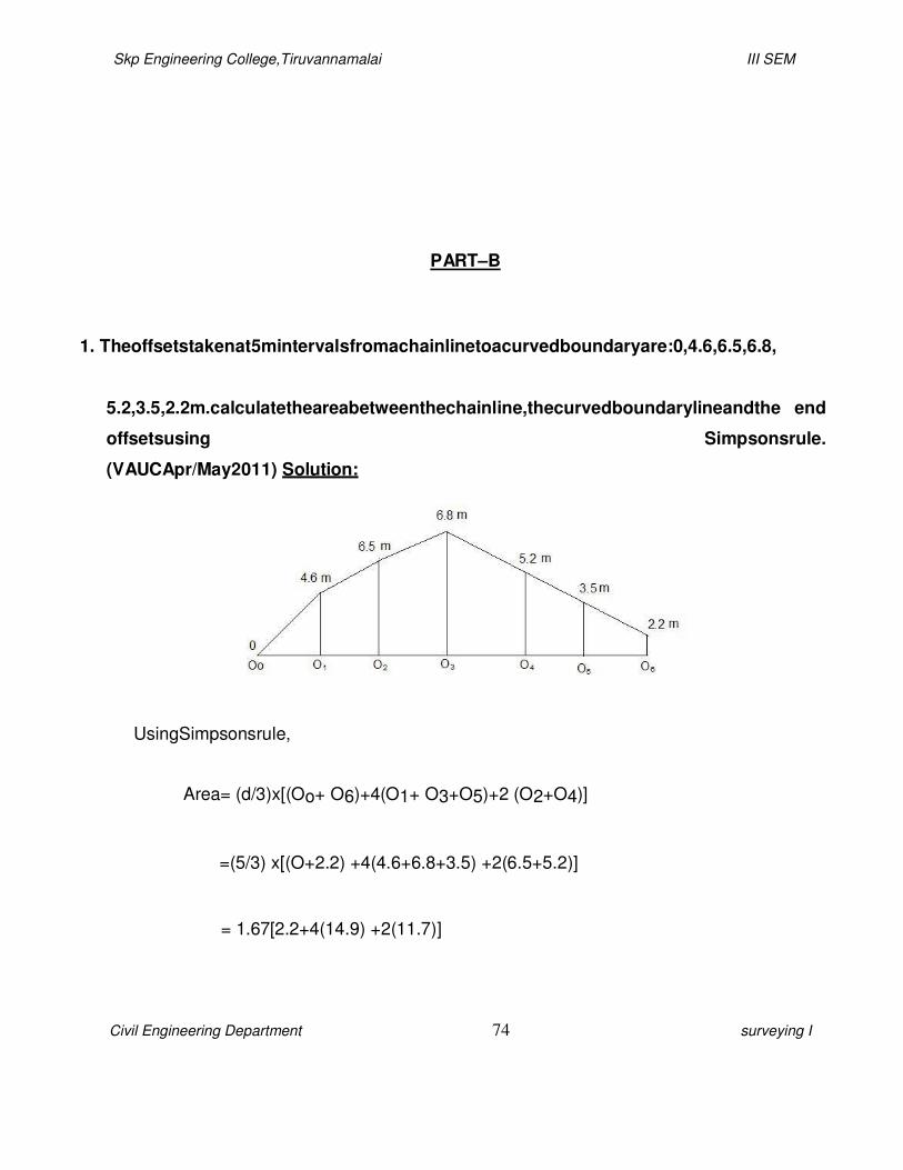
1. Theoffsetstakenat5mintervalsfromachainlinetoacurvedboundaryare:0,4.6,6.5,6.8,
5.2,3.5,2.2m.calculatetheareabetweenthechainline,thecurvedboundarylineandthe end
offsetsusing Simpsonsrule.
(VAUCApr/May2011) Solution:
UsingSimpsonsrule,
Area= (d/3)x[(Oo+ O6)+4(O1+ O3+O5)+2 (O2+O4)]
=(5/3) x[(O+2.2) +4(4.6+6.8+3.5) +2(6.5+5.2)]
= 1.67[2.2+4(14.9) +2(11.7)]
Skp Engineering College,Tiruvannamalai III SEM
Civil Engineering Department 75 surveying I
Area=142.28m2
2. Definecontoursand givecharacteristicsofcontours.
(AUCApr/May2011) Contours:
Acontour isanimaginarylineonthegroundpassingthroughpoints ofequal elevation.
CharacteristicsofContourLines
Characteristics ofcontour
linesarehelpfulinplottingandinterpretationofvariousfeaturesin the
map.Thesecharacteristicsareasfollows:

Skp Engineering College,Tiruvannamalai III SEM
Civil Engineering Department 76 surveying I
(a) Contour lineisalinejoiningpoints ofsameelevation;henceallpoints ofcontour lineshave
sameelevation.Theelevationofacontour iswrittenclosetothecontour.
(b) Twocontour lines of
differentelevationscannotintersecteachotherexceptincaseofan overhangingcliff or
acave(Figure1).
(c) Incaseofavertical cliffcontour lines of differentelevationscanjointoform onesingleline.
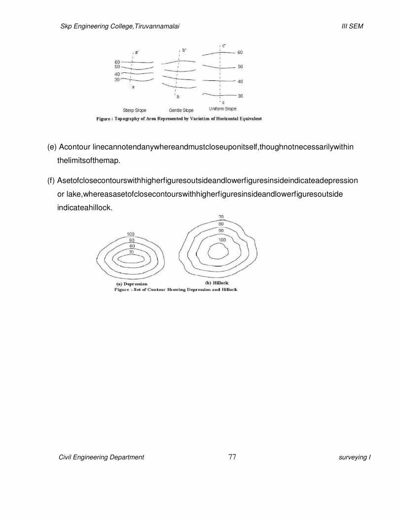
(d) Horizontalequivalentofcontoursindicatesthetopographyofthearea.Theuniformlyspaced
contourlinesindicateauniform slope,whilestraightandequallyspacedcontour linesindicatea
planesurface.Contour linesclosedtogether indicatesteepslope,whileagentleslopeis
indicatedwhencontour linesarefarapart.
Skp Engineering College,Tiruvannamalai III SEM
Civil Engineering Department 77 surveying I
(e) Acontour linecannotendanywhereandmustcloseuponitself,thoughnotnecessarilywithin
thelimitsofthemap.
(f) Asetofclosecontourswithhigherfiguresoutsideandlowerfiguresinsideindicateadepression
or lake,whereasasetofclosecontourswithhigherfiguresinsideandlowerfiguresoutside
indicateahillock.
Skp Engineering College,Tiruvannamalai III SEM
Civil Engineering Department 78 surveying I
(g) Contour linescrossawater shed(or ridgeline)andavalleylineatrightangles.Incaseofridge
line,theyform curves ofU-shapeacrossitwithconcavesideofthecurvetowardshigher
ground,whereasincaseofvalleyline,theyform sharpcurves ofV-shapeacrossitwithconvex
sideofcurvetowardshigher ground.
3. Explain
i. Reciprocallevelling
ii. Flylevelling
iii. Differentiallevelling
iv. Simplelevellingand statewhereeach isused. (CO1-H1-
AUCApr/May2011)
i) Reciprocallevelling:
Itisthe methodoflevellinginwhich thedifferenceinelevation between two pointsis
accuratelydeterminedbytwosetsofreciprocal observationswhenitisnot possibletoset upthe
levelbetweenthetwopoints.
Whenitis necessarytocarrylevellingacrossariver or any obstaclerequiringalongsight
betweentwopointssosituatedthatnoplacefor thelevelcanbefoundfromwhichthelengthsof
foresightandbacksightwill beevenapproximatelyequal.
Itmustbeusedtoobtainaccuracyandtoeliminate

Skp Engineering College,Tiruvannamalai III SEM
Civil Engineering Department 79 surveying I
Error ininstrumentadjustment.
Combinedeffectofearth’scurvatureandrefractionoftheatmosphere.
Variationsintheaveragerefraction.
ii) Differentiallevelling(Flylevelling):
Theoperationoflevellingtodeterminetheelevationofpointsatsomedistanceapartis
calledDifferentiallevelling.
Itisusuallyaccomplishedbydirectlevelling. Whentwopointsareatsuchadistancefrom
eachotherthattheycannotbewithinrangeofthelevelat thesametime.Thedifferencein
elevationisnotfoundbysinglesettingbutthedistancebetweenthepointsisdividedintwostages by
turningpointsonwhichthestaffisheld.Thedifferenceof elevationof eachofsucceedingpair of
suchturningpointsisfoundbyseparatesettingupofthelevel.
The image part with
relationship ID rId50 was not found i…
The image part with relationship ID rId51 was not found i…
The image part with relationship ID rId52 was not found i…
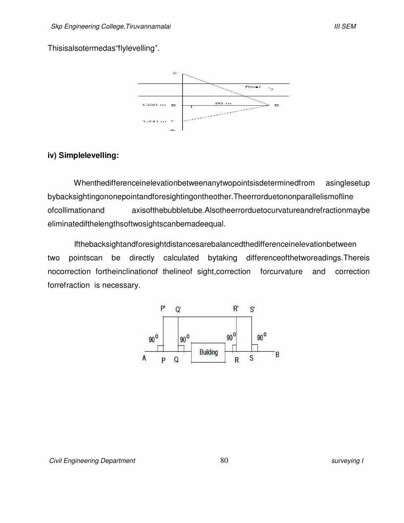
Skp Engineering College,Tiruvannamalai III SEM
Civil Engineering Department 80 surveying I
Thisisalsotermedas“flylevelling”.
iv) Simplelevelling:
Whenthedifferenceinelevationbetweenanytwopointsisdeterminedfrom asinglesetup
bybacksightingononepointandforesightingontheother.Theerrorduetononparallelismofline
ofcollimationand axisofthebubbletube.Alsotheerrorduetocurvatureandrefractionmaybe
eliminatedifthelengthsoftwosightscanbemadeequal.
Ifthebacksightandforesightdistancesarebalancedthedifferenceinelevationbetween
two pointscan be directly calculated bytaking differenceofthetworeadings.Thereis
nocorrection fortheinclinationof thelineof sight,correction forcurvature and correction
forrefraction is necessary.

Skp Engineering College,Tiruvannamalai III SEM
Civil Engineering Department 81 surveying I
4. Followingreadingswereobservedsuccessivelywithalevellinginstrument.Theinstrument
wasshiftedafterfifthandeleventhreadings0.585,1.010,1.735,3.295,3.775,0.350,1.300,
1.795, 2.575,3.375, 3.895,1.735,0.635and 1.605.Drawup apageoflevelbookand
determine theR.L of variouspointsif theRL of thepointon which thefirst reading was
taken is
135.00m.
(AUCNov/Dec2011) Solution:
Station B.S I.S F.S Rise Fall R.L
A 0.585 135.000
1.010 0.425 134.575
1.735 0.725 133.850
3.295 1.560 132.290
B 0.350 3.775 0.480 131.810
1.300 0.950 130.860
1.795 0.495 130.365
2.575 0.780 129.585
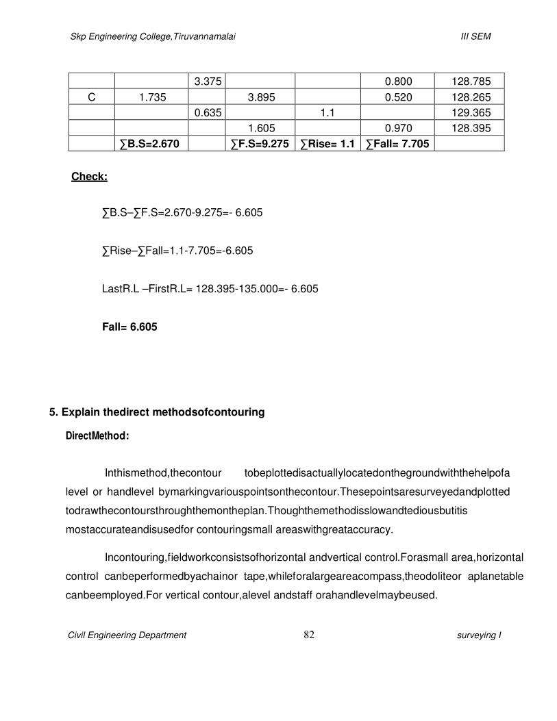
Skp Engineering College,Tiruvannamalai III SEM
Civil Engineering Department 82 surveying I
3.375 0.800 128.785
C 1.735 3.895 0.520 128.265
0.635 1.1 129.365
1.605 0.970 128.395
∑B.S=2.670 ∑F.S=9.275 ∑Rise= 1.1 ∑Fall= 7.705
Check:
∑B.S–∑F.S=2.670-9.275=- 6.605
∑Rise–∑Fall=1.1-7.705=-6.605
LastR.L –FirstR.L= 128.395-135.000=- 6.605
Fall= 6.605
5. Explain thedirect methodsofcontouring
DirectMethod:
Inthismethod,thecontour tobeplottedisactuallylocatedonthegroundwiththehelpofa
level or handlevel bymarkingvariouspointsonthecontour.Thesepointsaresurveyedandplotted
todrawthecontoursthroughthemontheplan.Thoughthemethodisslowandtediousbutitis
mostaccurateandisusedfor contouringsmall areaswithgreataccuracy.
Incontouring,fieldworkconsistsofhorizontal andvertical control.Forasmall area,horizontal
control canbeperformedbyachainor tape,whileforalargeareacompass,theodoliteor aplanetable
canbeemployed.For vertical contour,alevel andstaff orahandlevelmaybeused.
Skp Engineering College,Tiruvannamalai III SEM
Civil Engineering Department 83 surveying I
i) VerticalControlbyLeveland Staff:
Aseries ofpointshavingsameelevationarelocatedonthegroundinthismethod.An
instrumentstationonthegroundisselectedsothatitcommandsaview ofmostoftheareastobe
surveyed.Heightoftheinstrumentcanbefixedsightinganearestbenchmark.Staffreadingis
calculatedfor aparticular contourelevation.Thestaffmanisdirectedtomoveleftor rightalongthe
expectedcontour until therequired readingisobserved.Aseriesofpointshavingsameelevation
asshownbythesamestaffreadingareplottedandjoinedtogetasmoothcurve.
ii) VerticalControlbyHand Level:
Thesameprincipleasusedinlevelandstaffmethodisemployedinthismethodalso.This
methodisveryrapidincomparisontotheformermethod.Ahandlevel maybeusedtogetan
indicationofthehorizontal linefromtheeyeoftheobserver.Alevel staff orapolehavingzeromark
attheheightoftheobserver’seyewhichisgraduatedupanddownfrom thispointisusedinthis
method.Themanwiththeinstrumentstandsoverthebenchmarkandthestaffmanismovedtoa
pointonthecontour tobeplotted.Assoonasthemanwithinstrumentobservestherequiredstaff
readingforaparticular contourheinstructsthestaffmantostopandlocatesthepositionofthe point.

Skp Engineering College,Tiruvannamalai III SEM
Civil Engineering Department 84 surveying I
6. Aseriesofoffsetsweretakenfromachain lineto acurved boundarylineat intervalsof15m
inthefollowingorder0,2.65,3.80,3.70,4.65,3.60,4.95and5.85m.computethearea
betweenthechainline,curvedboundaryandendoffsetsbytrapezoidal ruleandSimpsons)
Solution:
Using trapezoidalrule:
Area=[{(Oo+O7)/2} +O1+O2+O3+O4+O5+O6]xd
=[{(0+5.85)/2}+2.65+3.80+3.70+4.65+3.60+4.95]x15
Area=394.13m2
Using Simpsonsrule:
Hereniseven,
UptoseventhordinatesolvebyusingSimpsonsruleand
Lasttwoordinatessolvebyusingtrapezoidal rule
Area1=(d/3) x[(Oo+O6)+4 (O1+O3+O5)+2(O2+O4)]
=(15/3) x[(O+4.95) +4(2.65+3.70+3.60) +2(3.80+4.65)]

Skp Engineering College,Tiruvannamalai III SEM
Civil Engineering Department 85 surveying I
Area1= 308.25m2
Area2={(O6+O7)/2}xd
={(4.95+5.85)/ 2}x15
= 81m2
Area=Area 1+Area 2=308.25+ 81
Area=389.25m2
7. Thefollowingconsecutivereadingsweretakenwithadumpylevel and4mlevellingstaffon
acontinuouslyslopinggroundat30mintervals.0.680,1.455,1.855,2.330,2.885,3.380,
1.055,1.860,2.265,3.540,0.835,0.945,1.530and 2.250.RL of thestarting pointwas
80.750m.
I. Ruleout apageofalevelbookand entertheabovereadings.
II. DeterminetheRL of variousstaff stations.
III. Estimateaveragegradientofground measured.

Skp Engineering College,Tiruvannamalai III SEM
Civil Engineering Department 86 surveying I
Solution:
Station B.S I.S F.S Rise Fall R.L
A 0.680 80.750
1.455 0.775 79.975
1.855 0.400 79.575
2.330 0.475 79.100
2.885 0.555 78.545
B 1.055 3.380 0.495 78.050
1.860 0.805 77.245
2.265 0.405 76.840
C 0.835 3.540 1.275 75.565
0.945 0.110 75.455
1.530 0.585 74.870
2.250 0.720 74.150
∑B.S=2.570 ∑F.S=9.170 ∑Rise=0 ∑Fall= 6.600
Check
:
∑B.S–∑F.S=2.570-9.170=- 6.600
∑Rise–∑Fall =0 –6.600=-6.600
LastR.L –FirstR.L= 74.150–80.750=-6.600
Fall= 6.600
Gradient
=
6.6
30X12

Skp Engineering College,Tiruvannamalai III SEM
Civil Engineering Department 87 surveying I
Gradient
=0.0183
Slope=1in 55
8. Discusstheeffectsofcurvatureandrefractioninlevellingandderivetheexpressionfor
thesecorrections. (CO1-H1-
AUCApr/May2010) Effects of Curvature:
BCisthedeparturefromthelevelline.Actuallythestaffreadingshouldhavebeentaken
atBwherethelevellinecutsthestaff,butsincethelevelprovides onlythe horizontallineofsight,
thestaffreadingis takenatthepointC.thus theapparentstaffreadingismoreandthereforethe
objectappearstobelowerthanreally.Thecorrectionforcurvatureisnegativeasappliedtothe
staffreadingitsnumerical valuebeingequal totheamountBC.TofindthevalueBCwehave
OC2=OA2+AC2,AngleCAObeing90o
LetBC =CC=correctionfor curvature
AB=d= horizontaldistancebetweenAandB

Skp Engineering College,Tiruvannamalai III SEM
Civil Engineering Department 88 surveying I
AO=R =radiusofearthinthesameunitasthatofd
(R +Cc)2=R2+ d2 (or)
R2+2RCc+Cc2=R2+ d2
Cc(2R+Cc)= d2 (or)
Cc=
d2
d2
=
2R CC2R
(NeglectingCcincomparisonto2R)
Tofindthecurvaturecorrection,dividethesquareofthelengthofsightby earth’sdiameter.
BothdandRmaybetakeninthesameunits,whentheanswerswillalsobeintermsofthatunit.
Theradiusoftheearthcanbetakenequalto6370km.ifdistobeinkmandR=6370km,Ccwill
beinmetres.
Effectsof Refraction:
Figure:Curvatureand Refraction
Theeffectofrefractionisthesameasiftheline ofsightwascurveddownwardorconcavetowards the
earth’ssurface andhencetherodreadingisdecreased.Therefore,theeffectofrefractionisto

Skp Engineering College,Tiruvannamalai III SEM
Civil Engineering Department 89 surveying I
2
maketheobjectsappearhigherthantheyreally arc.Thecorrectionasappliedtostaffreadingsis
positive. The refraction curve is irregular because of varying atmospheric conditions, but
for averageconditionsitisassumedtohaveadiameter aboutseventimesthatoftheearth.
d2
Thecorrectionofrefraction,Cr=
14R
(positive)
=0.01121d2meters,whendisinkm.
Thecorrectionduetocurvatureandrefractionwill begivenby
C= d
-
2R
d2
14R
3d2
=
7R
(negative)
=0.06728d2meters,dbeinginkm.
ThecorrespondingvaluesofthecorrectionsinEnglishunitsare:
2d2
CC= = 0.667d2feet
3

Skp Engineering College,Tiruvannamalai III SEM
Civil Engineering Department 90 surveying I
Cr=
C =
2d2
21
4d2
7
= 0.095d2feet
= 0.572d2feet
Wheredisinmilesandradiusofearth=3958 miles.
9. Thefollowingstaffreadingwereobservedsuccessivelywithaleveltheinstrumenthaving
beenmovedafterthird,sixthandeightreading2.228,1.606, 0.988,2.090,2.864,1.262, 0.602,
1.982,1.044,2.684m entertheabovereadinginapageoflevelbookandcalculateRLofthe
first reading was taken with astaff held on bench markof432.384m.
(CO1-H1-AUC Nov/Dec2010) (CO1-H1-AUCMay/June2013)
Solution:
Station B.S I.S F.S Rise Fall R.L
A 2.228 432.384
1.606 0.622 433.006
B 2.090 0.988 0.618 433.624
2.864 0.774 432.850
C 0.602 1.262 1.602 434.452
D 1.044 1.982 1.380 433.072
2.684 1.640 431.432

Skp Engineering College,Tiruvannamalai III SEM
Civil Engineering Department 91 surveying I
∑B.S=5.964 ∑F.S=6.916 ∑Rise=2.842 ∑Fall= 3.794
Check
:
∑B.S–∑F.S=5.964–6.916=-0.952
∑Rise–∑Fall=2.842–3.794=- 0.952
LastR.L –FirstR.L=431.432 –432.384=- 0.952
Fall= 0.952
10.Explain theindirectmethodsoflocating contours.
(CO1-H1-AUCApr/May2010
Indirect Methods:
Indirectmethodsarequicker,cheaperandlesslaboriousthandirectmethod.Inthis
method,aseries ofguidepointsareselectedalongasystem ofstraightlinesandtheir elevations
aredetermined.Thesepointsarethenplottedandcontoursaredrawnbyinterpolation.Theguide
pointsgenerallyarenotthepointsonthecontourstobelocatedexceptincaseofacoincidence. For
plottingofcontours,theinterpolationisdonewiththeassumptionthattheslopebetweenany

Skp Engineering College,Tiruvannamalai III SEM
Civil Engineering Department 92 surveying I
twoadjacentguidepointsisuniform.Someoftheindirect methods oflocatinggroundpointsare
givenbelow.
i)MethodsofSquares:
Thismethodisverysuitablewhentheareatobesurveyedissmall.Thismethodisalso
calledcoordinatemethodoflocatingcontours.Theareatobesurveyedisdividedintoanumberof
squaresformingagrid.Thesideofasquaremayvaryfrom5to20mdependinguponthenatureof
thecontour andcontour interval.Theelevations ofthecornerofsquaresarethendeterminedby
usingalevelandastaff.Thelevelsaretheninterpolatedandcontour linesaredrawn.Sometimes
rectanglesmayalsobeusedinplaceofsquares.
ii)Methodsof Cross-sections:
Thismethodisgenerallyusedin rootsurveys.Cross-sectionsareruntransversetothe
centrelineofacanal, roadandrailwayetc.Thespacingofcross-sectionsbasicallydependonthe
nature ofterrainandthecontour interval.The reducedlevel ofvariouspointsalongthesectionline
areplottedontheplanandthecontoursarethendrawnbyinterpolation.
Skp Engineering College,Tiruvannamalai III SEM
Civil Engineering Department 93 surveying I
iii) TacheometricMethod:
Thismethodissuitableforhillyareas.Inthismethod,anumber oflinesaresetout radiating
atagivenangular intervalfromdifferenttraversestations.Therepresentativepointsontheselines
arelocatedinthefieldbyobservingverticalanglesandthestaffreadingofthestadiawiresofa
tacheometer.Theelevationsandthedistances ofthesepointsarecalculatedandplottedandthen
contour linesaredrawnbyinterpolation.

Skp Engineering College,Tiruvannamalai III SEM
Civil Engineering Department 94 surveying I
11.Explain themethod of profilelevelling. (CO1-H1-AUCMay/June2013)
(AUCNov/Dec2009)
i)Longitudinal
ProfileLevellingii)
CrossSectionalProfiling
i) LongitudinalProfileLevelling:
Letthecentral lineofrequiredroutebeABCDasshowninFigure9.Notethatthechange
pointsA,B,C,Detcareabout30m to70mapart,notmorethan100m innormal conditions.Staff
intermediatestations,e.g.1,2...11etc.areusually5to20mdistant.Theinstrumentissetupata
suitablefirmground(sayO),properlylevelledandadjusted,from whichlargenumber ofstaff
stationscanbecommanded.Backsightisthentakenonthebench marktodetermineHI,the
reducedlevel oflineofcollimationatinstrumentstationO.
Staffreadingsarethentakenstarting fromstationA followedbyreadingsatpredetermined
intervals of5m or 10m,measuringthedistanceA-1,1-2etc.bystretchingthechainonalignedline

Skp Engineering College,Tiruvannamalai III SEM
Civil Engineering Department 95 surveying I
AB.Inadditiontointermediatestations1,2, 3etc.,readingsarealsotakenatcriticalorimportant
pointsontheground,i.e. pointsindicatingchangeofslopeor other importantfeatures(e.g.sp1,sp
2etc.).
Whenthelengthoflineofsightexceedsvisibilitylimit,e.g. about 100m orso, orifthereis
someobstructioninthelineofsight,theinstrumentisrequiredtobeshiftedtonewposition(sayO).
ForesightonstaffstationBistakenfrominstrumentstationO1 beforeshiftingtheinstrumentfrom
positionO1toO2.Whentheinstrumentisset,levelledandadjustedatO2,thefirstreadingrecorded
fromO2 willbethebacksightatB.ThiswilldecidetheRLofnewlyestablishedcollimationplane.
Thedistanceofintermediateandspecial points arecontinuedtobemeasuredalonglineBCand
levelsreadateachofthesestations.Previously establishedbenchmarksareimportant points on
whichstaffreadingsarenecessarilytakenasacheckonlevelmeasuringprocess.Benchmarks
canalsobeusedaschangepoints.

Skp Engineering College,Tiruvannamalai III SEM
Civil Engineering Department 96 surveying I
Toplotthelongitudinalprofileofthegroundalongthesurveyline, firststepwouldbetofixa
datumlineandmarkingthechainagesoftheintermediate,special andchangepointsonitata
suitablescale.Verticallinesarethendrawnonthischainagelineat eachintermediate,special and
changepoints.Therespectivelevels arethenmarkedontheselines.Thelinejoiningtheseplotted
pointsrepresents thelongitudinal groundprofile.
ii) CrossSectionalProfiling:
Theprojectfacilitywhetheritishighway,railway,pipeline,ortransmissionline,willhave
certainwidth.Hence,inadditiontoobtaininginformationalongthelongitudinal section,itisalso
necessary togather useful informationuptodesiredtransversedistanceonbothsideoftheline
alongitsentirelength.Thisisachievedbydrawingperpendicular linesatdesiredinterval (e.g. 20m
to30m) allalongtheroutelength.Thetransversewidth(lengthofcrosssection) oneither sidewill
dependuponthefacilityrequirements.Itis30m to60m for highways,and200m to300m for
railwayson eachsideofthecentreline(Figure11).Thecrosssectionsarethenseriallynumbered,
e.g. CS1, CS2etc. Along eachcross section line, staff intermediate and special stationsare
determined atwhichlevelreadings aretaken andrecorded.Theintermediatestations can be
atan intervalof10meterswhilespecialstations are fixedatallimportantpoints,e.g.pointsofsudden
changeoflevels.Therecordingofreadingsanddrawingthe profileisexactlysimilar to thatof
longitudinalprofiling.

Skp Engineering College,Tiruvannamalai III SEM
Civil Engineering Department 97 surveying I
Themapwill thenbeabletosupplyinformationabout
a) Original groundlevel,
b) Formationlevel,
c) Finishedsurfacelevel,
d) Depthofcuttingorfilling,
e) Proposedgradient,and
f)If anyother usefulinformationneededforexecutionoftheconstructionproject.
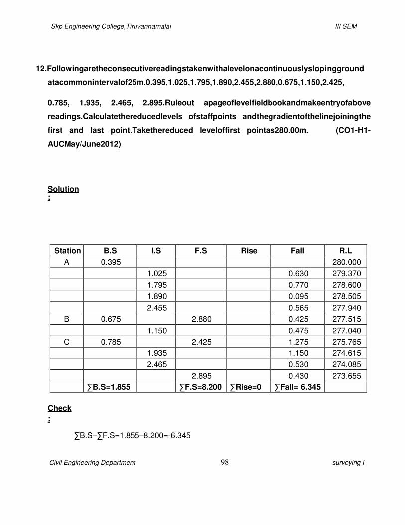
Skp Engineering College,Tiruvannamalai III SEM
Civil Engineering Department 98 surveying I
12.Followingaretheconsecutivereadingstakenwithalevelonacontinuouslyslopingground
atacommonintervalof25m.0.395,1.025,1.795,1.890,2.455,2.880,0.675,1.150,2.425,
0.785, 1.935, 2.465, 2.895.Ruleout apageoflevelfieldbookandmakeentryofabove
readings.Calculatethereducedlevels ofstaffpoints andthegradientofthelinejoiningthe
first and last point.Takethereduced leveloffirst pointas280.00m. (CO1-H1-
AUCMay/June2012)
Solution:
Station B.S I.S F.S Rise Fall R.L
A 0.395 280.000
1.025 0.630 279.370
1.795 0.770 278.600
1.890 0.095 278.505
2.455 0.565 277.940
B 0.675 2.880 0.425 277.515
1.150 0.475 277.040
C 0.785 2.425 1.275 275.765
1.935 1.150 274.615
2.465 0.530 274.085
2.895 0.430 273.655
∑B.S=1.855 ∑F.S=8.200 ∑Rise=0 ∑Fall= 6.345
Check
:
∑B.S–∑F.S=1.855–8.200=-6.345

Skp Engineering College,Tiruvannamalai III SEM
Civil Engineering Department 99 surveying I
2
2
∑Rise–
∑Fall =0 –
6.345=-
6.345
LastR.L –FirstR.L= 273.655–280.000=- 6.345
Fall= 6.345
Gradient =
=
Fall
L(N )
6.345
25(13 )
Gradient =0.0231
Slope=1in 43

Skp Engineering College,Tiruvannamalai III SEM
Civil Engineering Department 100 surveying I
0
13.Following observationsweretaken in areciprocallevelling:
Instrumentat Staff reading at
A B
A 1.625 2.545
B 0.725 1.405
DeterminetheRLofBifthatofA is100.00mandalsotheangularerrorincollimationifthe
distancebetween Aand B is1000m. (CO1-H1-
AUCMay/June2012) Solution:
i) DetermineRL of B :
Observationtakenfrom A,
DifferenceinelevationbetweenA&B=2.545-1.625
=0.92m(Aishigher)
ObservationtakenfromB,
DifferenceinelevationbetweenA&B=1.405–0.725
=0.68m(Aishigher)
Truedifferenceinelevation=
0.92
2
.68
=0.8m

Skp Engineering College,Tiruvannamalai
Civil Engineering Department
R.L of B=100
ii) Combined correction for
Correction=0.06728
=0.06728x
=0.06728m
iii) Errorin observation= 0
Error duetocollimation=0
=0
Collimationerror ispositive
tanα=
0.052
7
1000
Buttan60” =0.000290
tan
tan60"
Skp Engineering College,Tiruvannamalai
101
0
0–0.8=99.2m
orcurvatureandrefraction:
8d2
8x(1)2
8m (Bislower)
0.92 –0.8=0.12m
0.12–0.06728
0.0527m
e.
.0000527
09
III SEM
surveying I
α=

Skp Engineering College,Tiruvannamalai III SEM
Civil Engineering Department 102 surveying I
0.0000527
0.0002909
527x60
2909
α=10.86”= 11”(upwards)

Skp Engineering College,Tiruvannamalai III SEM
Civil Engineering Department 103 surveying I
14.Thefollowingstaffreadingswereobservedsuccessivelywithalevel.Theinstrumenthaving
beenmovedafterthesecond,fifthandeighthreadings.0.675,1.230,0.750,2.565,2.225,
1.935,1.835, 3.220,3.115and2.875.thefirststaffreadingwastakenwithastaffheldona
benchmarkofreducedlevel 100.00m.enterthereadingsinthelevel bookformandfindthe
reduced levelsofallpoints. (CO1-H1-
AUCNov/Dec2012)
Solution:
Station B.S I.S F.S H.I R.L
A 0.675 100.675 100.000
B 0.750 1.230 100.195 99.445
2.565 97.630
C 1.935 2.225 99.905 97.970
1.835 98.070
D 3.115 3.220 99.800 96.685
2.875 96.925
∑B.S=6.475 ∑F.S=9.550
Check
:
∑B.S–∑F.S=6.475–9.550=-3.075
LastR.L –FirstR.L= 96.925–100.000=- 3.075
Fall= 3.075
Skp Engineering College,Tiruvannamalai III SEM
Civil Engineering Department 104 surveying I
15.Explain thesourcesofvariouserrorsin levelling. (CO1-H1-
AUCNov/Dec2012)
Thesourcesoferrorsinlevellingexercisecanbeseveraldependinguponthelocation,
instrumentemployedandhumanresource.Themajor sourcescanbelistedasfollows
(a) Instrumental errors.
(b) Humanerrorsinsetting.
(c) Natural causes.
a)InstrumentalErrors:
a) Thefocusingtubemaybefaultycausingsometiltinginlineofsightwhilefocusing.
b)Thebubblemaybesluggishorinsensitive.Itcanremainincentral positionevenwhen
bubbletubeisnothorizontal.
c)Morecommonandseriousinstrumentalerrorismaladjustment oflevel.Thebubble tube
lineandcollimationline do notremain parallel.Evenwhen thebubbletubeishorizontal,the
collimationline mayremaininclined.
d) Thestaff graduationsmaynotbeaccurategivingwrongresults.

Skp Engineering College,Tiruvannamalai III SEM
Civil Engineering Department 105 surveying
I
b)HumanErrors:
Inaccuratelevellingofinstrument bysurveyor whilesettingtheinstrument, or
settlingoflevel duringsurveyingintroduceserrors.Theerror iscumulative.Theerror
canbeavoidedbytakingcare tosetthelevel inafirm groundandlevellingitcarefully.Ifsettingonsoft
groundcannotbeavoided, thelegs ofleveltripodarekeptonwoodenplatformoronstakes
drivenintheground.Thesame
precautioncanbetakenatchangeandintermediatestationstoavoidstaffsettlement. Careshould
betakentoavoidanycontactwithtripodwhilesightingandtakingthestaffreading.Other human
errorscouldbeerrorinfocusingorstaffnotbeingheldperfectlyverticalwhiletakingthe
levelreadings,wrongrecordingofreadingsor recordinginwrongcolumnsetc.
c)NaturalCauses:
Theseareeffectsofwindandsun.Considerabledifficultycouldbeexperiencedwhile
takingthestaffreading underglaringsun, orsunshiningon theobjectiveglass. Accuracyof
observationcan also beaffectedwhen thevelocityofwindislargeorwhenthe atmosphereis
heated.Whenthesightsarelongduringprecisionlevellingtheerrorsduetoeffectofcurvatureand
refractionshall betakeninto account.Thelineoflevel,definedasalineofequalaltitude,willnot
remainhorizontal inlongsightsduetoearth’scurvature(Figure12).Aa′will betherecordedlevel at
AwhilethereallevelshouldbeAa.Thus,anerrore=aa′isintroducedduetoearth’scurvature
givenasec=0.0785D2,whereD isthedistanceinkilometer (km) fromthelevel tothestaffstation,
andeisinmeters.Innormallevelling,sightlengthislessthan300m,henceewillalwaysbeless
than0.007 m.

Skp Engineering College,Tiruvannamalai III SEM
Civil Engineering Department 106 surveying
I
Errorsduetorefractionsareintroducedduetorefractionoflightpassingthroughlayersof
airofdifferent densities.Thebentlightrayfromstafftoinstrumentwillnotremainhorizontal(Figure
13)butwillbecurvedintroducingerroraa′.Theeffectofrefractionisnotconstantbutvarieswith
atmosphericconditions.However,onanaverageundernormal.

Skp Engineering College,Tiruvannamalai III SEM
Civil Engineering Department 107 surveying I
atmosphericconditions thecorrectionforrefractionwillbeaa′.Theerror,er(inmeters)=0.0112D2
(i.e. roughly about 1/7 the correction due to curvature and opposite in sign). The
combined correctionduetocurvatureandrefractionwouldbeeCO=eC–er=(0.0785–
0.0112)D2=0.0673
D2.Astheeffectofcurvatureistoincreasethestaffreadingsothecorrectionforcurvatureis
subtractive.Thecorrectionfor refractionisadditivetostaffreading.Hence,thecombinedcorrection
issubtractivetostaffreading.
16.Comparetheriseandfalland lineofcollimation methodsin reducing leveling observation.
(CO1-H1-AUC May/June2013)
Riseand FallMethod:
Insteadoffinding theinstrument heightatasetupstation,thedifferencebetween
consecutivepointsisobtained from theirstaffreadingswiththatimmediately precedingit.The
differenceindicatesariseorafall.Thereducedlevelofeachpointisthenobtainedbyaddingthe
risetoor subtractingthefall from theRLoftheprecedingpoint.Thearithmeticcheckinthismethod
isasfollows:
Skp Engineering College,Tiruvannamalai III SEM
Civil Engineering Department 108 surveying I
Σ BS–Σ FS=Σ Rise–ΣFall
= LastRL–FirstRL
Itcanbenoted thatthe firstmethod ofcollimationissimplerand faster than theriseand fall
method.However, thereis nocheckinreductionoflevelsatintermediatestationsincollimation
methodwhilethesecondmethodprovidesarithmeticcheckonallthelevelreductions. Wecan
concludethatthe collimationmethodcan bepreferred forprofilelevellingorsetting
outconstruction levels,whileriseand fallmethodispreferred
fordifferentiallevelling,checklevellingandother importantapplications.
Someprecautionsinrecordingthemeasurementsinfieldbooksshouldbetakentoavoid
errorinrecordingandsubsequentcomputations.Careshouldbetakentomakeentriesstrictlyin
therespectivecolumns prescribedfortheminorderoftheirobservation.Thefirstentryonafresh
pagein fieldbookshall alwaysbeabacksightwhilethelastentryisaforesight.Ifthelastentry
happenstobeastaffpositionatintermediatepoint,insteadofachangepoint,itshall bemadeboth
inforesightandbacksightcolumns atthe endof the preceding page andas thefirstentryintothe
succeeding page. In the remark column, bench marks, change points and other important

Skp Engineering College,Tiruvannamalai III SEM
Civil Engineering Department 109 surveying I
informationshallbebrieflybutaccuratelyrecorded,preferablyexplainedwiththehelpofsketches
byfreehanddrawnontheleftsideofthepage.
CollimationMethod:
Asexplainedearlier,theheightofinstrument(HI),e.g.theheightoflineofcollimation
aboveBM(stationofknownlevel)ateachinstrumentstationis determined by
addingthebacksightofBMstationtoreducedlevelofBM.Fromthisheightofinstrumentataparticularinstrum
ent station,reducedlevelsofallthestationpointsongroundarecalculatedbysubtracting foresightof
thatparticular stationfromHI,i.e.
HIofinstrument=RLofBenchmark+BSofBM
RLofintermediatepoint=HI–FSatintermediatestation
=HI–IS
Whentheinstrumentisshiftedtoitssecondposition,heightofinstrument atnewsetup
stationisrequiredtobedetermined.Thisisachievedbycorrelating thelevelsoftwocollimation planes(first
andsecondposition)byforesightofchangepointfrom
firstsetupstationandbacksightofsamechangepointfrom secondsetupstation,asfollows:
RLofchangepointC=RLofA+BSatA–FSatC
HI(atsecondstationO2)=RLofC+BSatC
Withinstrumentsetupatsecondstation(sayO2),staffreadings atnewsystem of
intermediatestationsaretakenbeforeshiftingtheinstrumentatnextsetupstation(O3).This process is
continuously repeated till the levelling exercise is completed,and all the required
reducedlevelsareobtained.

Skp Engineering College,Tiruvannamalai III SEM
Civil Engineering Department 110 surveying I
Acheckcan beappliedonthemathematicalcorrectnessofcalculationofreducedlevelsby
collimationmethodasfollows.Thedifferencebetweenthefirstreducedlevel(atstartingstation)
andlastreducedlevel(at endstation)mustbeequaltothedifferencebetweensummationofall
foresightsatchangepointsandthesummationof all backsightsatchangepoints.

Skp Engineering College,Tiruvannamalai III SEM
Civil Engineering Department 111 surveying I
UNIT 4
LEVELLING APPLICATIONS
PART A
1. Reduced level of Bench Mark A (CO1-L1-AUC
NOV/DEC 14) - 50.000m Reading on
staff held at A - 2.435m
Reading on staff held at station point B -
1.650m Find: (a) Height of collimation.
(b) Reduced level of station point
B. (c) Rise/fall of B with respect
to A.
(a). Height of collimation = RL of BM A +
BS (HOC) = 50.000 +
2.435
= 52.435m
(b) Reduced level of station point B.
= HOC – FS.
= 52.435 - 1.650
Skp Engineering College,Tiruvannamalai III SEM
Civil Engineering Department 112 surveying I
= 50.785 m
( c). Rise/fall of B with respect to A.
= 2.435- 1.65 ( Lower staff reading being higher)
= 0.785m,
= with compare to A, the station point B being 0.785m higher.
2. Compare height of collimation method and rise and fall method.
SI.No Height of collimation method Rise and fall method
1. It is more rapid, less tedious and simpler as it involves few calculation.
It is more laborious and tedious , involving several calculations. 2. There is no check on the RL of
the There is a check on the RL of the
3. Errors in intermediate RL’s cannot be
Errors in intermediate RL’s can be
4. There are two arithmetic checks on
the accuracy of RL calculation.
There are three arithmetic checks
on the accuracy of RL calculation.
5. It is suitable in the case of L.S and
It is suitable in fly leveling where I
3. Write the formula for curvature correction, refraction correction
and combined correction. (CO1-L1-AUC NOV/DEC 14)
Curvature correction CC = 0.07849 d2 ( negative) m

Skp Engineering College,Tiruvannamalai III SEM
Civil Engineering Department 113 surveying I
Refraction correction Cr = 0.01121 d2
(positive) m
Combined correction. C = CC – Cr = 0.06728 d2
(negative) m. Note: ‘d’ is to be substituted in Km, while the corrections will be in m.
4. List out the various sources of errors in levelling.
Three principal sources:
(i). Instrumental error
a. Error due to imperfect
adjustment b. Error due to
sluggish bubble.
c. Error due to movement of objective
slide. d. Error due to defective joint.
e. Error due to incorrect length of
staff. (ii). Natural error.
a. Earth’s
curvature.
b. Atmospheric
refraction.
c. Variations in
temperature. d.
Settlement of tripod.
e. Wind
vibrations. (iii). Personal
errors.

Skp Engineering College,Tiruvannamalai III SEM
Civil Engineering Department 114 surveying I
a. Mistakes in manipulation. b. Mistake in staff handling
c. Mistake in reading the staff. d. Error’s in sighting.
e. Mistakes in recording.
5. List out the leveling problems. (CO1-L1-AUC NOV/DEC 14)
1. Levelling on Steep Slope.
2. Levelling on Summits and Hollows.
3.Taking Level of an Overhead Point.
4. Levelling Ponds and Lakes too Wide to be Sighted across.
5. Levelling across River.
6. Levelling on Past High Wall.
6. Define sensitivity of a bubble. State any two factors affecting the same.
The sensitiveness of a bubble is defined the angular value of one
division of the bubble tube. It means the capability of showing small angular
movements of the tube vertically. It can be increased by:
1. Increasing the internal radius of the tube.
2. Increasing the diameter of the tube.
3. Increasing the length of the tube.
4. Decreasing the roughness of the walls.
Skp Engineering College,Tiruvannamalai III SEM
Civil Engineering Department 115 surveying I
5. Decreasing the viscosity of the liquid.
7. What is a spire test?
It is used to make the horizontal axis perpendicular to the vertical
axis. This test is also known as the test for the adjustments of the standards. It
is done by means of the adjustments of the vertical hair. It is one of the
permanent adjustment of the level and theodolite.
8. Define Contour, contour interval and, horizontal equivalent. (CO1-L1-AUC
NOV/DEC 14)
Contour: A contour is an imaginary line on the ground joining the
points of equal elevation.
Contour interval: It is the vertical distance between any two
consecutive contours. It depends upon the nature of the ground, the scale of
the map and the purpose of the survey.
Horizontal equivalent: It is the horizontal distance between any two
consecutive contours. It varies according to the steepness of the ground.
9. What are the different Characteristics of contour?
1. Contour lines are closed curves. They may either within the map
itself or outside the map depending upon the topography.
2. Uniformly spaced, contour lines indicate a uniform slope.
3. A series of closed contours with increase in elevation from
outside to inside in plan denotes a hill.
Skp Engineering College,Tiruvannamalai III SEM
Civil Engineering Department 116 surveying I
4. A series of closed contours with increase in elevation from
inside to outside in plan denotes a depression.
5. The spacing between the contour lines depends upon the slope of
the ground. In steep slopes, the spacing is small and for gentle slope, the
spacing is large.
PART B
1. Describe in detail how would you proceed profile leveling or longitudinal
sectioning in the field. (CO1-H1-AUC MAY/JUNE 2015)
Profile Leveling
Profile leveling is a method of surveying that has been carried out along the central
line of a track of land on which a linear engineering work is to be constructed/ laid.
The operations involved in determining the elevation of ground surface at small spatial
interval along a line is called profile leveling.
Stations

Skp Engineering College,Tiruvannamalai III SEM
Civil Engineering Department 117 surveying I
The line along which the profile is to be run is to be marked on the ground before
taking any observation. Stakes are usually set at some regular interval which depends
on the topography, accuracy required, nature of work, scale of plotting etc. It is
usually taken to be 10 meter. The beginning station of profile leveling is termed as
0+00. Points at multiples of 100m from this point are termed as full stations.
Intermediate points are designated as pluses.
Procedure
In carrying out profile leveling, a level is placed at a convenient location (say I1) not
necessarily along the line of observation. The instrument is to be positioned in such a
way that first backsight can be taken clearly on a B.M. Then, observations are taken
at regular intervals (say at 1, 2, 3, 4) along the central line and foresight to a properly
selected turning point (say TP1). The instrument is then re-positioned to some other
convenient location (say I2). After proper adjustment of the instrument, observations
are started from TP1 and then at regular intervals (say at 5, 6 etc) terminating at
another turning point, say TP2 . Staff readings are also taken at salient points where
marked changes in slope occur, such as that at X.
The distance as well as direction of lines are also measured.
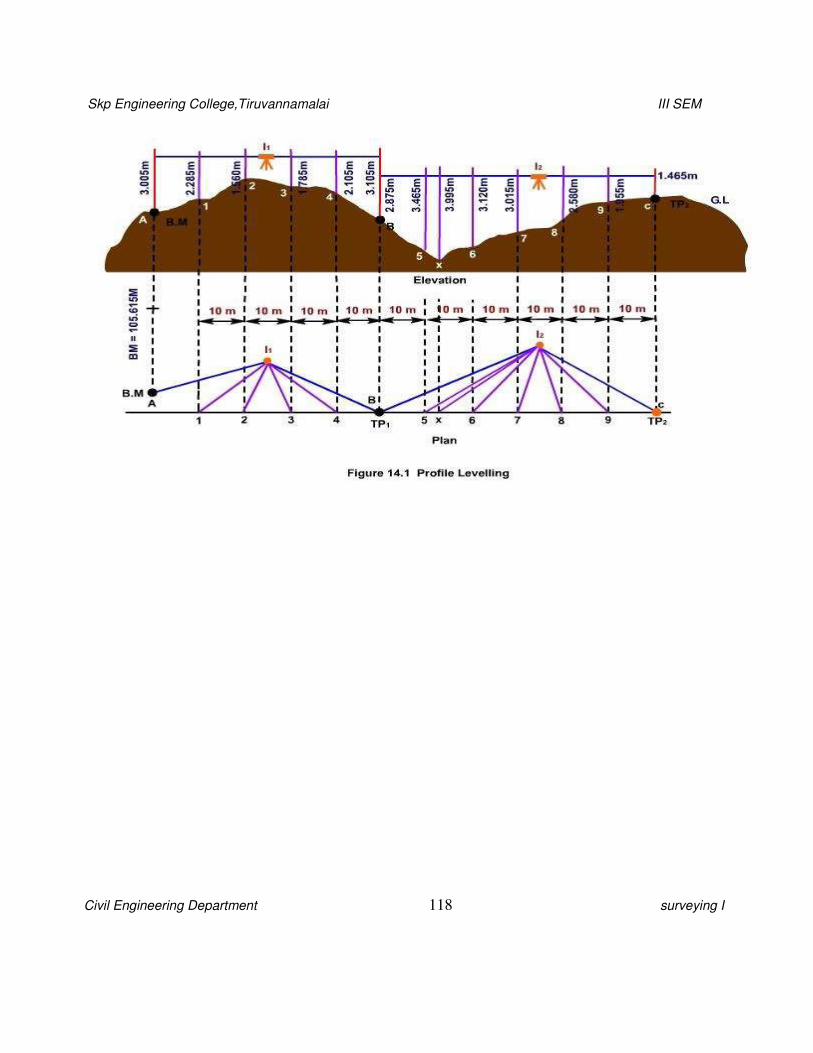
Skp Engineering College,Tiruvannamalai III SEM
Civil Engineering Department 118 surveying I
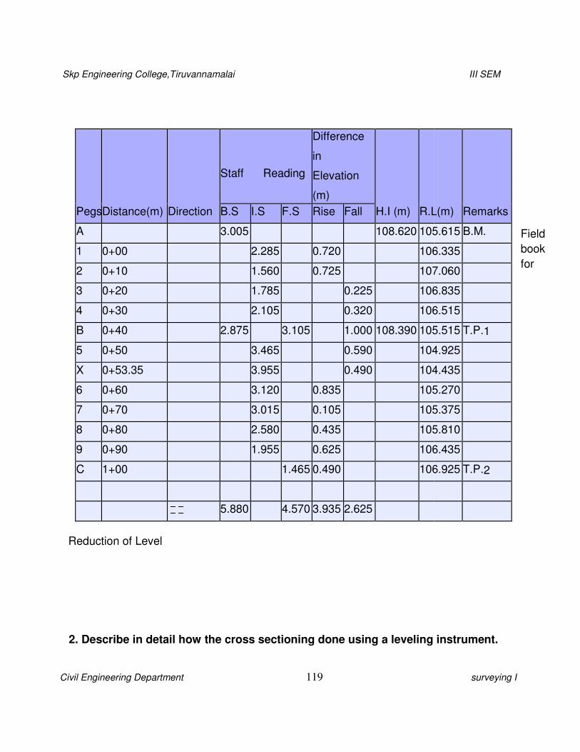
Skp Engineering College,Tiruvannamalai
Civil Engineering Department
Reduction of Level
2. Describe in detail how the
Pegs
Distance(m)
Direction
A
1 0+00
2 0+10
3 0+20
4 0+30
B 0+40
5 0+50
X 0+53.35
6 0+60
7 0+70
8 0+80
9 0+90
C 1+00
Skp Engineering College,Tiruvannamalai
119
e cross sectioning done using a leveling
Staff Reading
Difference
in
Elevation
(m)
H.I (m)
R.LB.S I.S F.S Rise Fall
3.005 108.620 105
2.285 0.720 106
1.560 0.725 107
1.785 0.225 106
2.105 0.320 106
2.875 3.105 1.000 108.390 105
3.465 0.590 104
3.955 0.490 104
3.120 0.835 105
3.015 0.105 105
2.580 0.435 105
1.955 0.625 106
1.465 0.490 106
5.880 4.570 3.935 2.625
III SEM
surveying I
Field
book
for
instrument.
R.L(m)
Remarks
105.615 B.M.
106.335
107.060
106.835
106.515
105.515 T.P.1
104.925
104.435
105.270
105.375
105.810
106.435
106.925 T.P.2
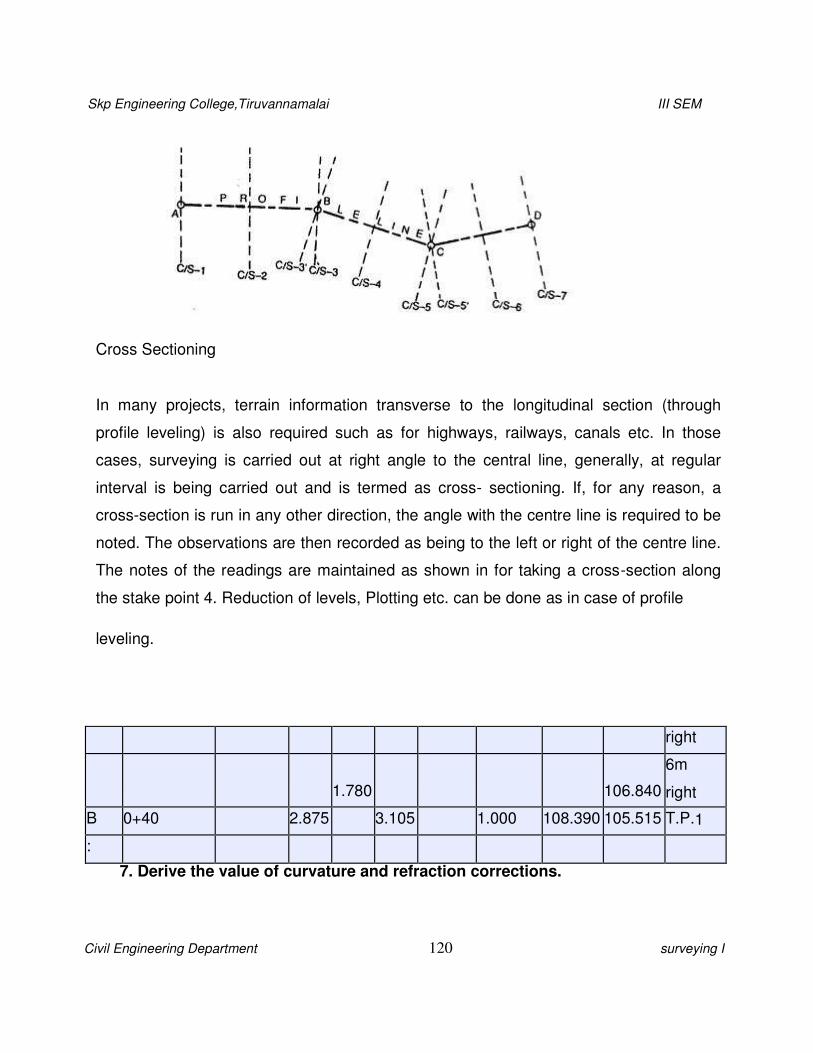
Skp Engineering College,Tiruvannamalai III SEM
Civil Engineering Department 120 surveying I
Cross Sectioning
In many projects, terrain information transverse to the longitudinal section (through
profile leveling) is also required such as for highways, railways, canals etc. In those
cases, surveying is carried out at right angle to the central line, generally, at regular
interval is being carried out and is termed as cross- sectioning. If, for any reason, a
cross-section is run in any other direction, the angle with the centre line is required to be
noted. The observations are then recorded as being to the left or right of the centre line.
The notes of the readings are maintained as shown in for taking a cross-section along
the stake point 4. Reduction of levels, Plotting etc. can be done as in case of profile
leveling.
right
1.780
106.840
6m
right
B 0+40 2.875 3.105 1.000 108.390 105.515 T.P.1
:
7. Derive the value of curvature and refraction corrections.
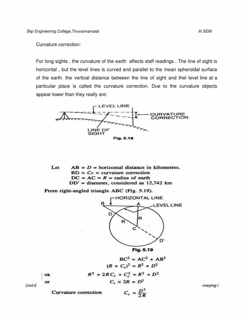
Skp Engineering College,Tiruvannamalai III SEM
Civil Engineering Department 121 surveying I
Curvature correction:
For long sights , the curvature of the earth affects staff readings . The line of sight is
horizontal , but the level lines is curved and parallel to the mean spheroidal surface
of the earth. the vertical distance between the line of sight and thel level line at a
particular place is called the curvature correction. Due to the curvature objects
appear lower than they really are:

Skp Engineering College,Tiruvannamalai III SEM
Civil Engineering Department 119 surveying I
CE6304 SU
It varies with temperature, terrain and other atmospheric conditions. It is
usually considered to be one seventh times but in opposite nature to the error due
to curvature. To minimize this error, reciprocal observation at the same instant of
time is required to be adopted.In actual field condition, the line of
sight through a level is not straight but it bends downward due to the
refraction of rays of light as it passes through the intervening medium.
Cr= 1/7 × (D2/2R)
3. When is reciprocal leveling done? Describe the method along with a
sketch.( CO1-H1-AUC MAY/JUNE 2015)
In the case of an obstacle like river valley, it is not possible to set the up the
level midway between two points on the opposite banks. In such cases the method
of reciprocal leveling is adopted, which involv3es reciprocal observations from
both banks of the river or valley. Two sets of staff readings are taken by holding the
staff on both banks. In this case it is found that the errors are completely eliminated
and the true difference of level is equal to the mean of the two apparent
differences of level. The principle is explained as follows.
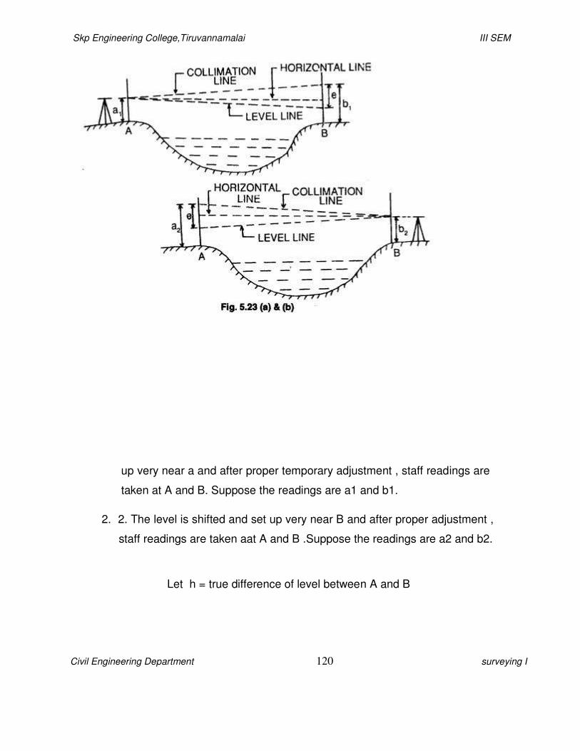
Skp Engineering College,Tiruvannamalai III SEM
Civil Engineering Department 120 surveying I
up very near a and after proper temporary adjustment , staff readings are
taken at A and B. Suppose the readings are a1 and b1.
2. 2. The level is shifted and set up very near B and after proper adjustment ,
staff readings are taken aat A and B .Suppose the readings are a2 and b2.
Let h = true difference of level between A and B

Skp Engineering College,Tiruvannamalai
Civil Engineering Department
1. Differentiatebetweenlatitudesa
S.No Latitude
(L) 1.
It maybedefined as itsclength
measuredparallel
2. Thelatitude of thelineisp
measurednorthward (u
is termedasnorthing. 3.
Thelatitude of thelineisn
measuredsouthward(dow
is termedassouthing. 4. L1=L1cosθ1
2. Whatarethe errorseliminated
Errorsduetoeccentricityo
vernierreadings.
Skp Engineering College,Tiruvannamalai
121
UNIT 5
THEODOLITE SURVEYING
PART A
esanddepartures. (CO1-L1-AUCApr/May2
e Departure
(D) coordinate It maybedefined as itscoor
measuredat rightangles
tothemeridian direction. spositivewhen
(upward)and
Thedepartureofthelineispo
measuredeastwardand
is termedaseasting. snegative when
ownward)and
Thedepartureofthelineisne
measuredwestwardand
is termedaswesting. D1=L1sinθ1
edinmeasurementofhorizontal anglebymeth
(CO1
A
ofverniersandcentresareeliminatedbytakingb
III SEM
surveying I
ay2011)
rdinate length
ositive when
egative when
hod ofrepetition?
CO1-L1-
AUCApr/May2011)
gboth

Skp Engineering College,Tiruvannamalai
Civil Engineering Department
Errorsduetoinadjustments
takingbothfacereadings.
Theerrorsdueto inaccurate
partsofthecircle.
Errors duetoinaccurateb
extentcounter-balanced
3. WhatisGale’stable? State
Traversecomputations a
Characteristics:
Thesumofalltheobserved
Ifexterioranglesaremeas
Skp Engineering College,Tiruvannamalai
122
ntsoflineofcollimationand thetrunnionaxisaree
s.
ategraduationsare eliminatedbytaking therea
ebisection oftheobject,eccentriccenteringetc.,
cedin differentobservations.
ate its characteristic.
AUCApr/May2010)
ns areusuallydonein atabular formiscalled Gal
edinterioranglesisfoundwhichshouldbeequalto
asuredthenthesumshould beequalto(2n+4) ri
III SEM
surveying I
sareeliminatedby
adingsatdifferent
, maybe tosome
c. (CO1-L1-
le’stable.
o(2n-4)right angle.
ightangles.
Skp Engineering College,Tiruvannamalai
Civil Engineering Department
Thereducedbearingsofal
lines.
Thelatitude anddepartu
The independentcoord
coordinates.
4. Whatkindoferrorcanbe elimin
Errordueto lineof collimati
axis. Errordueto horizontal
Errordueto non-parallelism
Errordueto imperfect adj
5. Whatismeantbyparallax? Nov/Dec2011)
Parallaxisaconditionarising
thecrosshairs.
6. Name thetemporaryadjustments
Nov/Dec2011)
Setting
Levellingand
Skp Engineering College,Tiruvannamalai
123
llthelinesarecomputedbasedonthewholecircl
ure ofall thelinesarecomputed.
dinatesof thelinesareobtainedfromthe corrected co
natedbytaking faceleft andfaceright obse
(CO1-L1-A
ation not beingperpendiculartothehorizontal
al axisnotbeingperpendicular tothevertical a
smof theaxisoftelescopelevel and lineofcollim
justmentof theverticalcircle vernier.
? (CO1
ngwhentheimageformedbytheobjectiveisnot
mentsinatransittheodolite. (CO1-L1-AUC M
III SEM
surveying I
lebearingofthe
ected consecutive
ervations?
AUCApr/May2010)
cal axis.
mation.
CO1-L1-AUC
tintheplaneof
May/June 2012,
Skp Engineering College,Tiruvannamalai
Civil Engineering Department
Parallaxremoval.
7. Whatistransit theodolite?( CO1
Atransittheodoliteison
180oin thevertical
plane.
8. Whatistheuse of Gale’stable?
Nov/Dec2010)
Thesumoflatitudes(∑L)a
Necessarycorrectionsare done
The independent coordin
coordinates.
Thecoordinatesare posit
9. Whatiscentering ofa theodoli
Theprocessof setting theth
Skp Engineering College,Tiruvannamalai
124
CO1-L1-AUC Nov/Dec2010)
neinwhichthelineofsightcanbereversedbyrev
e?
)anddepartures (∑D) arefound.
e done in closedtraverse suchthat∑L= Oand
nates of the lines are obtained from corrected co
tive and theentiretraverselie in thefirstquadra
ite?( CO1-L1-AUC Nov/Dec2009)
heodoliteexactlyoverthestation markisknown as
III SEM
surveying I
volvingthetelescope
e? (CO1-L1-AUC
d ∑D =O.
ected consecutive
drant.
n asCentring.

Skp Engineering College,Tiruvannamalai
Civil Engineering Department
10.Whatisfacerightobservation?
If thefaceofthe vertical circ
11.Briefhowatheodolitecan be usedasa
Afterhavingcentred andapproximate
of footscrewsand with referenceto
levelsdependsuponwhether three
12.How wouldyou eliminate par
Nov/Dec2012)
Parallaxiseliminatedin two
steps, Focusing
theeyepiece
Focusing theobjective
Skp Engineering College,Tiruvannamalai
125
?( CO1-L1-AUC Nov/Dec 2009)
cle is totherightof theobserverisknown asface
n be usedasalevel.( CO1-L1-AUC May/June 20
ately levelledtheinstrument.Accuratelevelling
otheplatelevels.Themanner oflevellingtheins
eelevellingscrewsorfour levellingscrews.
e parallaxintheodolite?
III SEM
surveying I
acerightobservation.
012)
ngisdonewith thehelp
nstrument bytheplate
e? (CO1-L1-AUC

Skp Engineering College,Tiruvannamalai III SEM
Civil Engineering Department 126 surveying I
PART–B (16marks)
1. Describe brieflyabouttemporaryand permanentadjustmentsofatheodolite.
(CO1-H1-AUC May/June 2013) TemporaryAdjustments:
i) Setting
ii) Levelling
iii) Parallaxremoval
i) Setting:
Thevertical axisoftheinstrumentshall belocatedexactlyabovethesurveystationposition
markedbyapegpermanentlyfixedinground.Thetopofthepegisnormallymarkedwithacross by
permanentpaint.In normal theodolites,a hookisplacedinthecentreoftripodstand
representingthepositionofverticalaxisoftheinstrument.Aplumbbobissuspendedfromthis hook
with thehelpofa strong thread.
Theinstrumentassembly issetonthefirmgroundandtripodlegsaremanipulatedtobe
approximately overthestationpoint. Thelegsarethenmovedsidewaysand/orradially tobring
plumbbobexactlyoverthe cross junctionon pegwhilemaintainingtribachhorizontal.In more
refined theodolites,opticalplummetisusedforcenteringinplaceofplumbbobassemblyforbetter
Skp Engineering College,Tiruvannamalai III SEM
Civil Engineering Department 127 surveying I
accuracy.Acenteringplatemountedontripodcanalsobeused forrapidly centeringthe
instruments.
ii)Levelling:
Toensure thatthehorizontal circledoeslieinatruehorizontal planewhichisnormal to
verticalaxisoftheinstrument,thetheodoliteislevelled.Thisisdonewiththehelpofleveling
screwsand platebubbles.Normally,theinstrumenthas threelevelingscrewsand two
platebubble tubes. Theupperplateoftheinstrumentis rotateduntil one ofthebubble tube is
parallelto theline
joiningtwolevelingscrews.Whilethesecondbubbletubewillbenormaltothisline.Thebubble of
the firsttubeisbroughttocentralpositionbymovingthecorrespondingpairoflevelingscrews
simultaneously.Thethirdscrewisthenmanipulatedtobringbubblesinsecondbubbletube
midwayofitsrun. Thismovementmaycause disturbance in positionoffirstbubble.
Theprocessof levelingisthen iterated untilbubblesofboththe tubes
remainslockedupincentralpositioninall
rotationsofupperhorizontalplate.Thiswillensureperfecthorizontality ofhorizontalcircleand
makesinstrument’svertical axis trulyvertical.

Skp Engineering College,Tiruvannamalai
Civil Engineering Department
I
iii)ParallaxRemoval:
Itconsistsoffocusingoft
objectlenscoincidethecrosshai
oftheobjectlensandeyepiecesc
tubeuntilthecrosshairsaredist
islockedinfocusedcondition.A
objectandthefocusingscrewis
mayberequiredeverytimethed
observation. Thisensures tha
PermanentAdjustments:
AsexplainedinElement
beidentifiedas:
vertical axis,
axes ofplate levels,
lineofcollimation(alsokn
trunnionaxis (orhorizont
Bubble lineof thealtitude l
Foraninstrument togive
mustexistbetweentheabovefu
Skp Engineering College,Tiruvannamalai
128
theeyepieceandobjectlenssothatthefociofthee
airsplane.Asafirststep,apieceofwhitepaperisp
ecescrewismanipulatedtomoveeyepieceinorouto
tinctlyandclearlyobservable.Thisprocessensures
Asanextstep,thetelescopictubeisdirectedtowardsad
sturneduntiltheobject’simageappearssharpan
hedistancebetweentheobjectandinstrumentcha
at theimage ofobjectisformedin theplane of the
tsofSurveying(Unit6),thefundamentalaxesoft
soknown aslineofsight),
tal axisortransverseaxis), and
e level (orazimuthal axis).
ereliableandaccurateobservations,certainde
undamentalaxesoftheinstrument.Theserelati
III SEM
surveying
heeyepieceand
splacedinfront
ofinstruments
suresthateyepiece
ardsadistinct
ndclear. Thisstep
angeswhilemaking
hecrosshairs.
thetheodolitecan
efinitiverelationships
ationshipsmustalso
Skp Engineering College,Tiruvannamalai
Civil Engineering Department
I
be maintained during theen
arethe properties ofthe instru
Therelationshipswhichm
asfollows:
Theplatelevelsaxisisnorm
Thehorizontal axisisnorm
Lineofcollimation mustbep
Thetelescope’saxismustbep
Inaddition toabovere
requirementstomakethe instru
Theonlymovementofonep
notbe anybacklash,wh
Theverniersofavernierty
vertical circle verniersh
Skp Engineering College,Tiruvannamalai
129
ntiresurveyingexercise.It maybenoted that t
umentanddonotchange with surveystationpos
mustexistbetweenfundamentalaxesoftheinstr
rmalto vertical axis.
rmal to vertical axis.
stbeperpendiculartohorizontal axis.
stbeparallel tolineofcollimation.
elations,thewelladjustedtheodoliteshouldalso
umentworkingeasilyand smoothly.
epartrelativetoanothershouldbealongacirculararc.
hip orlooseness.
ypetheodoliteshallbediametricallyoppositetoe
ershould read zerowhen theinstrument islevelle
III SEM
surveying
these relationships
sitions.
rumentcan belisted
someet following
ararc.There should
oeachother.The
ed.

Skp Engineering College,Tiruvannamalai III SEM
Civil Engineering Department 130 surveying I
2. Writeshortnotesonbalancingoftraverse.Listoutthedifferentmethodsofbalancinga
traverse.( CO1-H1-AUCApr/May2011)
Thetermbalancingisgenerallyappliedtotheoperationofapplyingcorrectionstolatitudes
anddeparturessothat∑L=0and∑D=0.Thisappliesonlywhenthesurveyformsaclosed polygon.
Thefollowingare commonmethods of adjusting traverse:
i) Bowditch’s method
ii) Transit method
iii) Graphicalmethod
iv) Axis method
i)
Bowditchrule:
Thebasisofthismethodisontheassumptionsthattheerrorsinlinearmeasurements
areproportional to l wherelis thelengthofaline. TheBowditch’s rule is also termedasthe
compassrule.Itismostlyusedtobalanceatraversewherelinearandangularmeasurementsare
equalprecision.Thetotalerrorinlatitudeandinthedepartureisdistributedinproportiontothe
lengthsof
thesides.
Bowditch
Ruleis
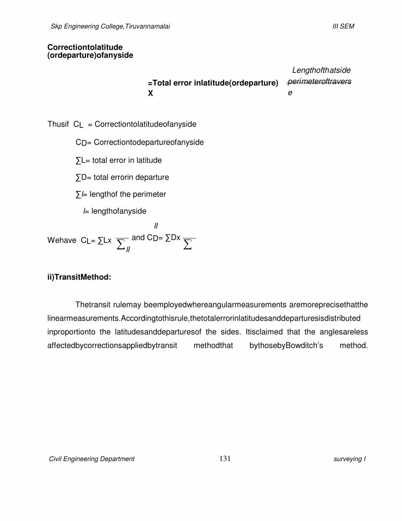
Skp Engineering College,Tiruvannamalai III SEM
Civil Engineering Department 131 surveying I
Correctiontolatitude (ordeparture)ofanyside
=Total error inlatitude(ordeparture)
X
Thusif CL = Correctiontolatitudeofanyside
CD= Correctiontodepartureofanyside
∑L= total error in latitude
∑D= total errorin departure
∑l= lengthof the perimeter
l= lengthofanyside
Lengthofthatside
perimeteroftravers
e
Wehave CL= ∑Lx
ll
and CD= ∑Dx
ll
ii)TransitMethod:
Thetransit rulemay beemployedwhereangularmeasurements aremoreprecisethatthe
linearmeasurements.Accordingtothisrule,thetotalerrorinlatitudesanddeparturesisdistributed
inproportionto the latitudesanddeparturesof the sides. Itisclaimed that the anglesareless
affectedbycorrectionsappliedbytransit methodthat bythosebyBowditch’s method.

Skp Engineering College,Tiruvannamalai III SEM
Civil Engineering Department 132
surveying I
The transit ruleis:
Correctiontolatitude (ordeparture)ofanyside
= Total error
inlatitude(ordeparture)X
Where L=latitude ofanyline
D=departure of any line
LT=arithmeticsumoflatitudes
DT=arithmeticsumof departure
Latitude(departure)ofthatlin
e
Arithmeticsumoflatitudes(departur
es)
L
Wehave,CL= ∑L x
LT
D
andCD= ∑Dx
DT
iii) Graphical method:
Forroughsurvey,suchasacompasstraverse, theBowditchrulemay beapplied
graphically withoutdoing theoreticalcalculations. According tothegraphicalmethod, it is not
necessarytocalculatelatitudesanddeparturesetc.howeverbeforeplottingthetraversedirectly
fromthefieldnotes,theanglesorbearingsmaybeadjustedtosatisfythegeometricconditionsof
thetraverse.

Skp Engineering College,Tiruvannamalai III SEM
Civil Engineering Department 133
surveying I
ThepolygonAB’C’D’E’A’representsanunbalancedtraversehavingaclosingerrorequal
toA’AsincethefirstpointAandthelastpointA’arenotcoinciding.The totalclosingerrorAA’is
distributedlinearlytoallthesidesinproportiontotheirlengthbya graphicalconstructionshownin
figure.AB’,B’C’,C’D’etcarerepresent thelengthofthesidesofthe traverseeithertothe same
scaleorreducedscale. TheordinateaA’ismadeequalto theclosingerrorA’A.byconstructing
similartriangles, thecorrespondingerrorsbB’,cC’,dD’,eE’are found.ThelineseE’,dD’,cC’,bB’
respectively. ThepolygonABCDEsoobtainedrepresentsthe adjustedtraverse. It shouldbe
remembered thattheordinatesbB’,cC’,dD’,eE’,aA’representthe correspondingerrorsin
magnitude onlybut not in direction.
iv)AxisMethod:
Thismethodisadoptedwhentheanglesaremeasuredveryaccurately,thecorrections
beingappliedtolengthsonly.Thustheonlydirectionsofthelineareunchangedandthegeneral

Skp Engineering College,Tiruvannamalai III SEM
Civil Engineering Department 134 surveying
I
shapeofthediagramispreserved.Toadjusttheclosingerroraa1 ofatraverseabcdefa1 the
followingprocedureisadopted.
Joina1aandproduceittocutthesidecdinx.thelinea1xisknownastheaxisof
adjustment.Theaxisdivides thetraverseintwo parts i.e. ab c xand a1fed x.
Bisecta1ainA.
Join xb,xe and xf.
ThroughA,draw alineABparalleltoabcuttingxbproducedinB.throughB,draw alineBC
parallelto bccuttingxcproduced inC.
Similarly,through A,draw AF parallel to a1fto cut xfin F.through F,draw FE parallelto
feto cutxe inE. throughE, drawED parallel to edto cutxd inD.
ABCDEF(thicklines)istheadjustedtraverse.
The image part with relationship ID rId66 was not found i…
The
image part with relationship ID rId67 was not found i…
The image part with relations
hip ID rId68 was not found i…
The image part with relationship ID rId69 was not found i…
The image part with
relationship ID rId70 was not found i…
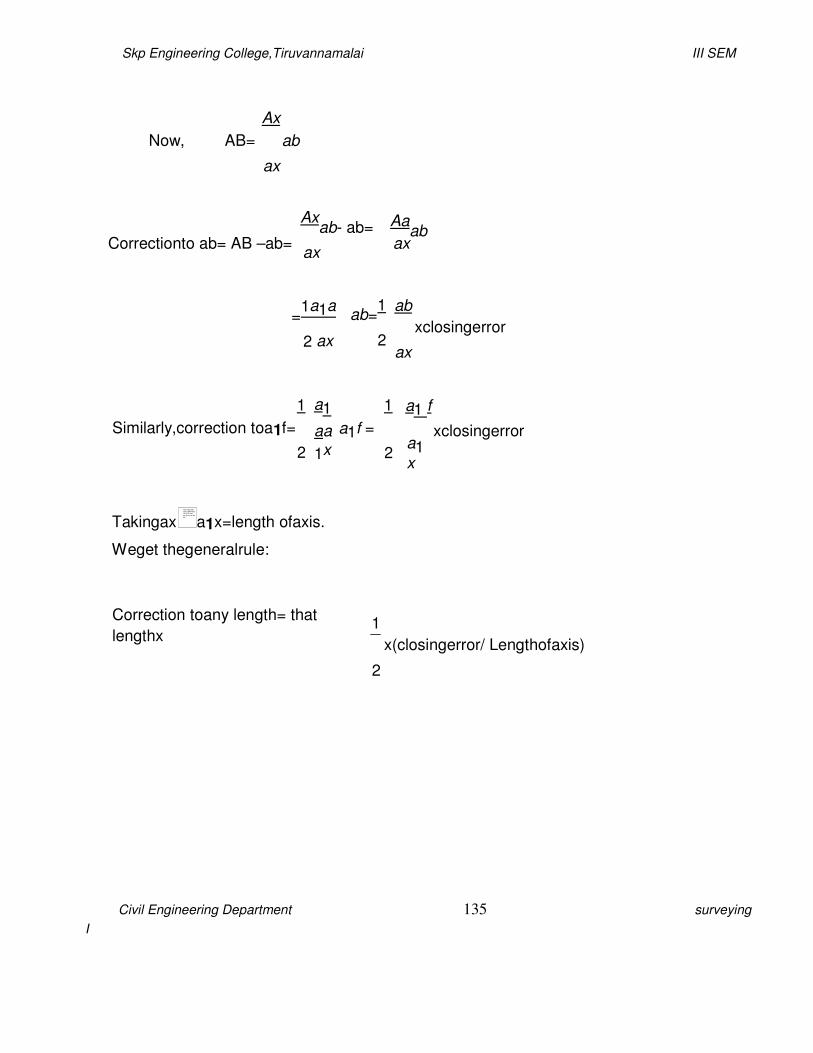
Skp Engineering College,Tiruvannamalai III SEM
Civil Engineering Department 135 surveying
I
Ax
Now, AB= ab
ax
Correctionto ab= AB –ab=
Axab- ab=
ax
Aaab
ax
=1a1a
2 ax
ab=1
2
ab
xclosingerror
ax
1
Similarly,correction toa1f=
2
a1
aa
1x
1
a1f =
2
a1 f
a1x
xclosingerror
Takingax a1x=length ofaxis.
Weget thegeneralrule:
Correction toany length= that
lengthx
1
x(closingerror/ Lengthofaxis)
2
The image part with relationship ID rId71 was not found in the file.
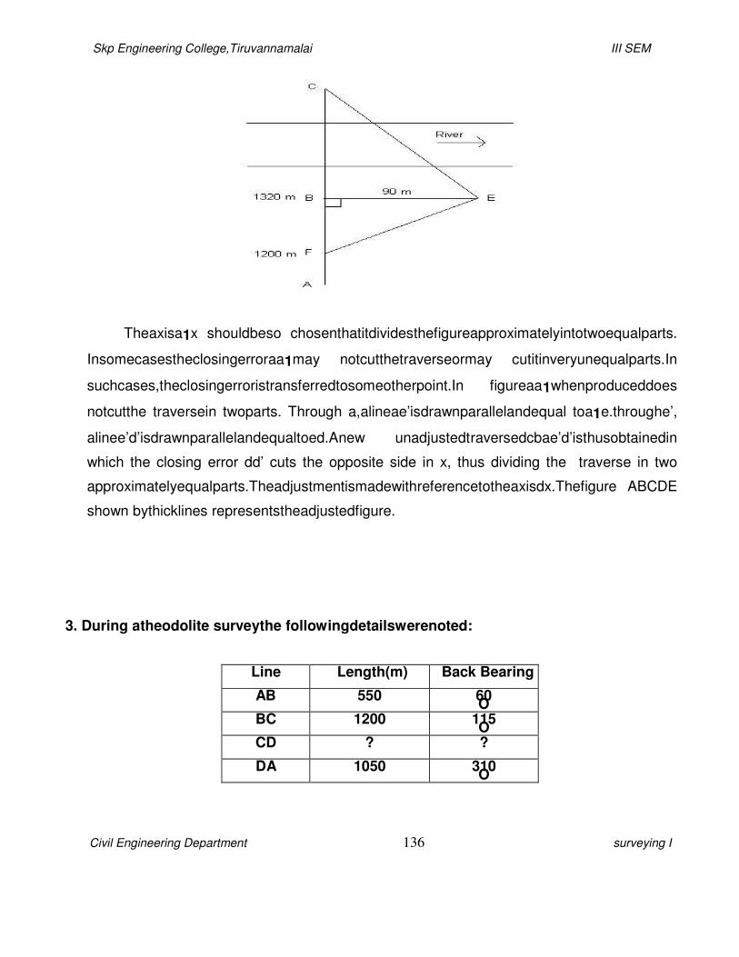
Skp Engineering College,Tiruvannamalai III SEM
Civil Engineering Department 136 surveying I
Theaxisa1x shouldbeso chosenthatitdividesthefigureapproximatelyintotwoequalparts.
Insomecasestheclosingerroraa1may notcutthetraverseormay cutitinveryunequalparts.In
suchcases,theclosingerroristransferredtosomeotherpoint.In figureaa1whenproduceddoes
notcutthe traversein twoparts. Through a,alineae’isdrawnparallelandequal toa1e.throughe’,
alinee’d’isdrawnparallelandequaltoed.Anew unadjustedtraversedcbae’d’isthusobtainedin
which the closing error dd’ cuts the opposite side in x, thus dividing the traverse in two
approximatelyequalparts.Theadjustmentismadewithreferencetotheaxisdx.Thefigure ABCDE
shown bythicklines representstheadjustedfigure.
3. During atheodolite surveythe followingdetailswerenoted:
Line Length(m) Back Bearing
AB 550 60O
BC 1200 115O
CD ? ?
DA 1050 310O

Skp Engineering College,Tiruvannamalai III SEM
Civil Engineering Department 137 surveying I
Calculatethelengthand bearingofthelineCD. (CO1-H1-AUCApr/May2011)
Solution:
Line
Latitude Departure
+ - + -
AB 275 476.31
BC 507.14 1087.56
DA 674.92 804.34
Sum 949.92 507.14 1563.87 804.34
∑LI= 442.78 ∑DI= 759.53
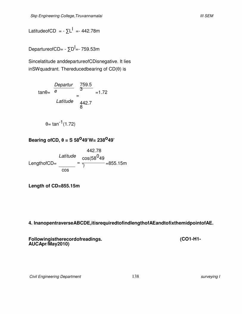
Skp Engineering College,Tiruvannamalai III SEM
Civil Engineering Department 138 surveying I
LatitudeofCD = - ∑LI =- 442.78m
DepartureofCD= - ∑DI=- 759.53m
Sincelatitude anddepartureofCDisnegative. It lies
inSWquadrant. Thereducedbearing of CD(θ) is
tanθ=
Departur
e
Latitude
759.53
=
442.78
=1.72
θ= tan-1(1.72)
Bearing ofCD, θ = S 58o49’W= 238o49’
LengthofCD=
Latitude
=
cos
442.78
cos(58049
')
=855.15m
Length of CD=855.15m
4. InanopentraverseABCDE,itisrequiredtofindlengthofAEandtofixthemidpointofAE.
Followingistherecordofreadings. (CO1-H1-AUCApr/May2010)

Skp Engineering College,Tiruvannamalai III SEM
Civil Engineering Department 139 surveying I
Line Length(m) Bearing
AB 130.5 N20O30’E
BC 215.0 N60O15’E
CD 155.5 N30O30’E
DE 120.0 N30O30’E
i) Determinethelengthand bearingofAE.
ii) AlsodeterminethelengthandbearingoflinejoiningmidpointofAEandthestation
C.
Solution
:
Line
Latitude Departure
+ - + -
AB 122.24 45.70
BC 106.68 186.66
CD 133.98 78.92
DE 103.39 60.90
Sum 466.29 372.18
∑LI= 466.29 ∑DI= 372.18
LatitudeofEA = - ∑LI =- 466.29m
DepartureofEA= - ∑DI=- 372.18m
Skp Engineering College,Tiruvannamalai III SEM
Civil Engineering Department 140 surveying I
Sincelatitude anddepartureofEA isnegative. It lies inSWquadrant.
Thereducedbearing of EA(θ) is
tanθ=
Departur
e
Latitude
372.18
=
466.29
=0.798
θ= tan-1(0.798)
Bearing ofEA,θ= S 38o35’W= 218o35’
Length ofEA=
Latitude
=
cos
466.29
cos(38035
')
=596.51 m
Length of EA=596.51m
5. Explainhowtheheight ofatowercan be determinedwhenit isinaccessible.
(CO1-H1-AUCApr/May2010)
Tomeasuretheverticalangleoftowerwithrespecttoinstrumentstationoranyotherpoint.TheI
nstrumentsusedareRanging rods,Theodolite and stand.
TomeasuretheVerticalangle ofanobject A atastation“O”.
The image part with relationship ID rId72 was not found i…

Skp Engineering College,Tiruvannamalai III SEM
Civil Engineering Department 141 surveying I
Setuptheinstrumentover‘O’and level itwith referencetothealtitude bubble.
Setthe zeroof thevertical vernierexactlyto the zeroof theverticalcircle bymeans of
the vertical circle clampandtangent screw.
Bring thebubble ofthealtitude level tothecenter ofitsrun. The lineofCollimation isthus
made horizontal,while thevernierreadszero.
Loosen the vertical circleclamp,direct thetelescope towardstheobject‘A’,andsighted
approximately,clampthe vertical circle andbisect ‘A’ exactlybyturning
thetangentscrew.
Road both venires.Themean of thetwo,readingsgives thevalueofthe
requiredangle. Changethefaceoftheinstrument andrepeat the process.Themean of
the two vernier
readingsgives thesecond valueof therequiredangle.
Tomeasurethevertical angle between thetwo pointsA andB
Bisect‘A’ as beforeandnotethereadingsonthevertical circle.
Similarly,bisect‘B’ and notethereadingsonthe vertical circle.
The image part with relationship ID rId73 was not found i…
The image part with relationship ID rId74 was not found i…
The image part with relationship ID rId75
was not found i…
The image part with relationship ID rId76 was not found i…
The image part with relationship ID rId77 was not found i…
The
image part with relationship ID rId78 was not found i…
The image part with relationship ID rId79 was not found i…
The image part with relations
hip ID rId80 was not found i…
The image part with relationship ID rId81 was not found i…

Skp Engineering College,Tiruvannamalai III SEM
Civil Engineering Department 142 surveying I
Thesumordifferenceofthesereadingsw
illgivethevalueoftheanglebetweenA&B
as one ofthepoints isabove
andtheother belowthehorizontal
plane. Theformula
usedtofindtheheight ofthetoweris h1=
Dtanθ1
h2= Dtanθ2
Heightof total object,H= h1+ h2
R.Loftopof theobject = R.LofB.M+S+h1
R.Lofbottomof theobject = R.LofB.M+ S–h2
Aftertakingthereadingsfindthereducedleveloftopandbottomofthetower.Finallyby using
thereducedlevel find theheightof thetower.
The image part with relationship ID rId82 was not found i…
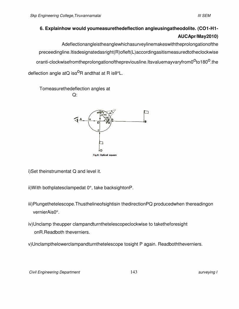
Skp Engineering College,Tiruvannamalai III SEM
Civil Engineering Department 143 surveying I
6. Explainhow would youmeasurethedeflection angleusingatheodolite. (CO1-H1-
AUCApr/May2010)
Adeflectionangleistheanglewhichasurveylinemakeswiththeprolongationofthe
preceedingline.Itisdesignatedasright(R)ofleft(L)accordingasitismeasuredtotheclockwise
oranti-clockwisefromtheprolongationofthepreviousline.Itsvaluemayvaryfrom0oto180o.the
deflection angle atQ isαoR andthat at R isθ°L.
Tomeasurethedeflection angles at
Q:
i)Set theinstrumentat Q and level it.
ii)With bothplatesclampedat 0°, take backsightonP.
iii)Plungethetelescope.Thusthelineofsightisin thedirectionPQ producedwhen thereadingon
vernierAis0°.
iv)Unclamp theupper clampandturnthetelescopeclockwise to taketheforesight
onR.Readboth theverniers.
v)Unclampthelowerclampandturnthetelescope tosight P again. Readboththeverniers.

Skp Engineering College,Tiruvannamalai III SEM
Civil Engineering Department 144 surveying I
Plungethetelescope.
vi)Unclamp theupper clampandturnthetelescope tosight R. read bothverniers.Sincethe
deflectionangle is doubledbytakingbothfacereadings, one-halfof thefinal readinggives
the deflectionangle at Q.
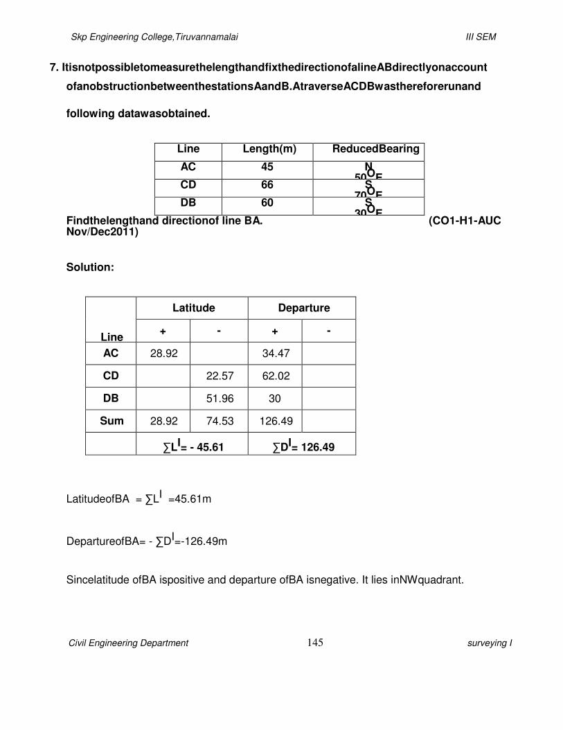
Skp Engineering College,Tiruvannamalai III SEM
Civil Engineering Department 145 surveying I
7. ItisnotpossibletomeasurethelengthandfixthedirectionofalineABdirectlyonaccount
ofanobstructionbetweenthestationsAandB.AtraverseACDBwasthereforerunand
following datawasobtained.
Line Length(m) ReducedBearing
AC 45 N 50OE
CD 66 S 70OE
DB 60 S 30OE
Findthelengthand directionof line BA. (CO1-H1-AUC Nov/Dec2011)
Solution:
Line
Latitude Departure
+ - + -
AC 28.92 34.47
CD 22.57 62.02
DB 51.96 30
Sum 28.92 74.53 126.49
∑LI= - 45.61 ∑DI= 126.49
LatitudeofBA = ∑LI =45.61m
DepartureofBA= - ∑DI=-126.49m
Sincelatitude ofBA ispositive and departure ofBA isnegative. It lies inNWquadrant.

Skp Engineering College,Tiruvannamalai III SEM
Civil Engineering Department 146 surveying I
Thereducedbearing of BA (θ) is
tanθ=
Departur
e
Latitude
126.49
=
45.61
=2.77
θ= tan-1(2.77)
Bearing ofBA,θ= N70o9’W= 289o51’
Length ofBA=
Latitude
=
cos
45.61
cos(7009'
)
=134.32 m
Length of BA=134.32 m
8. Explainthe variousmethods ofhorizontal angle using atheodolite.
(CO1-H1-AUC Nov/Dec2011
There aretwo methodstofindthehorizontal angle
usingatheodolite.Theyare i) Repetition Method
ii) ReiterationMethod
Skp Engineering College,Tiruvannamalai III SEM
Civil Engineering Department 147 surveying
I
RepetitionMethod
:
Tomeasure ahorizontal angle byrepetition
method.Theinstrumentsusedare
Transit theodolite,
Tripodand
Ranging rods(2no.s).
Procedure:
Setuptheinstrumentover‘O’ and level itaccurately.
Withthehelp of upper clampandtangent screw, set0º readingonvernier‘A’.Notethe
readingofvernier‘B’.
Release theupper clampand direct thetelescopeapproximatelytowardsthepoint‘P’.
Tightenthelowerclampandbisect point‘P’ accuratelybylowertangent screw.
Release theupper clampandturntheinstrument clock-wise towardsQ.Clamptheupper
clampandbisect ‘Q’ accuratelywith theupper tangentscrew.Notethereadingsofverniers
‘A’ and ‘B’ toget thevaluesoftheangle POQ.
The image
part with relationship ID rId83 was not found i…
The image part with relationship ID rId84 was not found i…
image part with relationship ID rId85 was not found i…
The
image part with relationship ID rId86 was not found i…
The image part with relationship ID rId87 was not
found i…
The image part with relationship ID rId88 was not found i…
The image part with relationship ID rId89 was not
found i…
Skp Engineering College,Tiruvannamalai III SEM
Civil Engineering Department 148 surveying
I
Release thelowerclampandturnthetelescope clockwise to sightP again.Bisect P
by using thelowertangent screw.
Release theupper clamp, turnthetelescopeclockwise and sight Q.Bisect Qbyusing
the upper tangent screw.
Repeattheprocessuntiltheanglemeasured(requirednumberof timesis3).Theaverage
angle withfaceleftwill be equal tofinalreadingdivided bythree.
Changefaceandmakethreemorerepetitionsasdescribed above.Findthe averageangle
withfaceright,bydividing thefinal readingbythree.
Theaveragehorizontal angle isthenobtained bytaking theaverageofthetwo angles with
faceleft andfaceright.
Aftertaking thereadingscalculatethehorizontal angle andhorizontal distancebyusing
the formula. Thenwefindthe exacthorizontal angleand thedistancebetween thepoints PQ.
The image part with relationship ID rId90 was not found i…
The
image part with relationship ID rId91 was not found i…
The image part with relationship ID rId92 was not found i…
The image
part with relationship ID rId93 was not found i…
The image part with relationship ID rId94 was not found i…

Skp Engineering College,Tiruvannamalai III SEM
Civil Engineering Department 149 surveying I
ReiterationMethod
:
Tomeasureahorizontal angle
byreiterationmethod.Theinstrumentsusedare
Transit theodolite,
Tripodand
Ranging rods(2no.s).
Procedure:
It is requiredtomeasureangles AOB, BOC,andCOD etcbyreiteration method.
Settheinstrument over“O” and level itset theVernierto zeroandbisectpointA accurately.
Loose theupper clampand turntheTelescopeclockwise topointB.BisectB byusing the
upper tangent screw.
Read boththeVerniers, the meanoftheVerniers will give theangles AOB.
Similarly,bisectsuccessively C,D etc, thusclosing thecircle. Read boththe
Verniersat each bisection.
The image
part with relationship ID rId95 was not found i…
The image part with relationship ID rId96 was not found i…
image part with relationship ID rId97 was not found i…
The
image part with relationship ID rId98 was not found i…
The image part with relationship ID rId99 was not
found i…
The image part with relationship ID rId100 was not found i…
The image part with relationship ID
rId101 was not found i…
The image part with relationship ID rId102 was not found i…

Skp Engineering College,Tiruvannamalai III SEM
Civil Engineering Department 150 surveying I
Finallysight toAthereadingof theverniershould bethesameastheoriginal setting
reading.
Repeatthe steps02to04 with otherfacei.e. faceRight.
Aftertaking thereadingsthen calculatethehorizontal anglefor each points.
9. Describethe essential parts ofa transit theodolite. (CO1-H1-AUC
Nov/Dec2009) EssentialParts:
Leveling head, telescope, vertical circle, index frame, A frame, lower plate, upper
plate,level tubes,plumbbob.
Leveling Head:-
Thelevelingheadconsistsoftwoparalleltriangularplanesknownastribrachplates.
Theuppertribrachhasthreearms,eachcarryingalevelingscrew. Thelowertribrachhas
threearms eachcarryingalevelingscrew. Thelowertribrachplateorfootplatehasacircular
holethrough which plumb bobmaybesuspended.
Telescope:-
Thetelescopeisanintegralpartofthetheodoliteandismountedonaspindleknown
ashorizontal axisortrunnionaxis. Inmostof thetransits, internalfocusingtelescopeisused.
The image part with relationship ID rId103 was not found i…
Skp Engineering College,Tiruvannamalai III SEM
Civil Engineering Department 151 surveying
I
Vertical Circle:-
The vertical axis is a circular graduated arc attached to the trunnionaxis of the
telescopeconsequentlythe graduatedarcratherwiththetelescopewhenthelatteristurned
aboutthe horizontalaxis.
IndexFrame:-
The indexframeisaT-shapedframeconsistingofaverticallegknownasclippingarm
andahorizontalbarknownasvernierarmofindexcorm.Atthetwoextremitiesoftheindex
armarefittedtwo verniers toreadthevertical circle.
AFrame:-
TwostandardsresemblingtheletterAaremountedontheupperplates. Thetrunnion
axisofthetelescope issupported onthese.
Lower Plate:-
Thelowerplateisattachedtotheouterspindle.Thelowerplatecarriesahorizontal
circleat itslevelededgeandisthereforealsoknownas thescale plate.
Upper Plate:-
Theupperplateorvernierplateisattachedtotheinneraxisandcarriestwovernierswith
magnifiers at two extremities diametrically opposite.Theupper plate supports the
standards.
PlumbBob:-
Aplumbbobissuspendedfromthehookfittedtothebottomoftheinneraxistocentre
ofinstrumentexactlyoverthestation mark.

Skp Engineering College,Tiruvannamalai III SEM
Civil Engineering Department 152 surveying
I
Telescope:
It consistsofeye-piece,objectglass andfocusingscrewand it isused tosight theobject.
Verticalcircle:
It isusedtomeasurevertical angles.
Footscrews:
These are usedto leveltheinstrument.

Skp Engineering College,Tiruvannamalai III SEM
Civil Engineering Department 153 surveying I

Skp Engineering College,Tiruvannamalai III SEM
Civil Engineering Department 154 surveying I
10.Explainthetheodoliteadjustmentforthelineofsight. (CO1-H1-AUC
May/June 2012)
Ifthelineofsightisnotperpendiculartothetrunnionaxisofthe telescope,itwillnotrevolve in
aplane when the telescope is raisedorloweredbutinstead,itwill traceoutthesurfaceofacone.
Thetraceoftheintersectionoftheconical surfacewith thevertical planecontainingthepointwill be
hyperbolic.Thiswillcauseerrorin the measurementofhorizontalangle betweenthepointswhich
areatconsiderable difference inelevation.
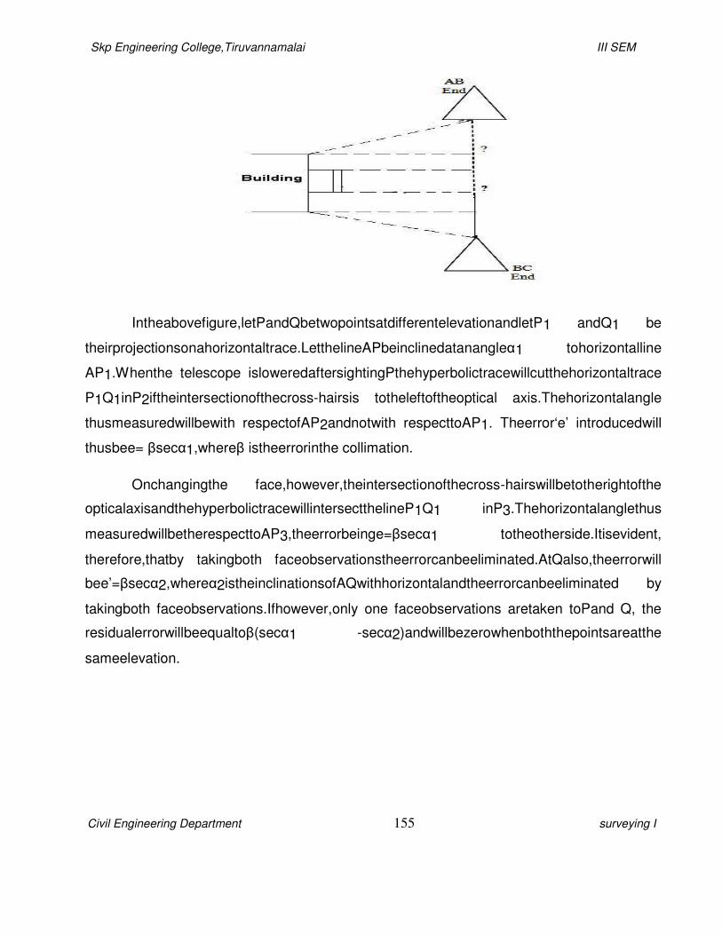
Skp Engineering College,Tiruvannamalai III SEM
Civil Engineering Department 155 surveying I
Intheabovefigure,letPandQbetwopointsatdifferentelevationandletP1 andQ1 be
theirprojectionsonahorizontaltrace.LetthelineAPbeinclinedatanangleα1 tohorizontalline
AP1.Whenthe telescope isloweredaftersightingPthehyperbolictracewillcutthehorizontaltrace
P1Q1inP2iftheintersectionofthecross-hairsis totheleftoftheoptical axis.Thehorizontalangle
thusmeasuredwillbewith respectofAP2andnotwith respecttoAP1. Theerror‘e’ introducedwill
thusbee= βsecα1,whereβ istheerrorinthe collimation.
Onchangingthe face,however,theintersectionofthecross-hairswillbetotherightofthe
opticalaxisandthehyperbolictracewillintersectthelineP1Q1 inP3.Thehorizontalanglethus
measuredwillbetherespecttoAP3,theerrorbeinge=βsecα1 totheotherside.Itisevident,
therefore,thatby takingboth faceobservationstheerrorcanbeeliminated.AtQalso,theerrorwill
bee’=βsecα2,whereα2istheinclinationsofAQwithhorizontalandtheerrorcanbeeliminated by
takingboth faceobservations.Ifhowever,only one faceobservations aretaken toPand Q, the
residualerrorwillbeequaltoβ(secα1 -secα2)andwillbezerowhenboththepointsareatthe
sameelevation.

Skp Engineering College,Tiruvannamalai III SEM
Civil Engineering Department 156 surveying I
11.List themethods ofcheckingin anopentraverseandclosedtraverse. (CO1-H1-AUC
May/June 2012) Checks inOpenTraverse:
Nodirectcheckofangularmeasurementisavailable.However,indirectcheckscanbemade
as shown inbelowfigures.
Skp Engineering College,Tiruvannamalai III SEM
Civil Engineering Department 157 surveying I
Infigure(a),inadditiontotheobservationofbearingofABatstationA,bearingofADcan
alsobemeasured,ifpossible.Similarly,atD,bearingofDAcanbe measuredandcheckapplied.If
thetwobearingsdifferby 180o,thework(uptoD)may beacceptedascorrect.Ifthereissmall
discrepancy,it canbeadjustedbeforeproceedingfurther.
Anothermethod,whichfurnishesacheckwhentheworkisplottedisasshowninfigure(b)
andconsistsinreadingthebearingstoanyprominentpointPfromeachoftheconsecutive
stations.ThecheckinplottingconsistsinlayingoffthelinesAP,BP,CP,etc.and nothingwhether
thelinespass throughonepoint.
Incaseoflongandprecise traverse,the angularerrorscanbe determinedby astronomical
observationsforbearingat regularintervalsduring theprogressofthetraverse.
Checks in closedTraverse:
Theerrors involved intraversing aretwokinds:linearand angular. Forimportantwork
the most satisfactorymethodofchecking thelinearmeasurementsconsists
inchainingeachsurvey linea secondtime,preferably in thereversedirectionondifferent
datesand bydifferent parties. Thefollowingarethechecksfortheangularwork.
1)Traversebyincluded angles:
a) Thesumof measuredinteriorangles shouldbeequalto(2N-4) right angles,where N=
numberofsidesofthetraverse.
b) Iftheexterior angles aremeasured, theirsumshouldbeequalto(2N +4) right angles.
2)Traversebydeflection angles:

Skp Engineering College,Tiruvannamalai III SEM
Civil Engineering Department 158 surveying I
Thealgebraicsumof thedeflectionanglesshould beequalto 360o,taking theright-
hand deflection angles aspositive and left-handanglesas negative.
3)Traverse bydirect observation ofbearings:
Theforebearingofthelastlineshould beequalto itsbackbearing+ 180omeasuredat the
initial station.
12.ThemeasuredlengthsandbearingsofthesidesofaclosedtraverseABCDEruninanti-
clockwisedirectionaretabulatedbelow.CalculatethelengthofCDandDE.
(CO1-H1-AUC May/June 2012)
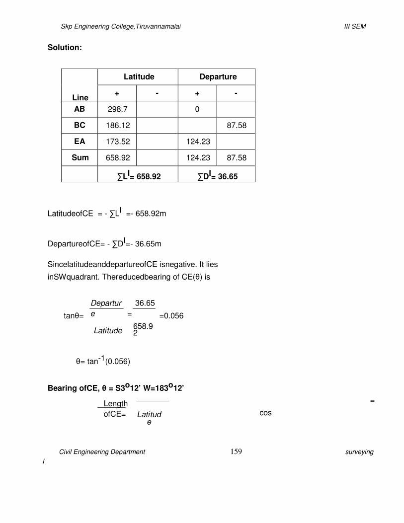
Skp Engineering College,Tiruvannamalai III SEM
Civil Engineering Department 159 surveying
I
Solution:
Line
Latitude Departure
+ - + -
AB 298.7 0
BC 186.12 87.58
EA 173.52 124.23
Sum 658.92 124.23 87.58
∑LI= 658.92 ∑DI= 36.65
LatitudeofCE = - ∑LI =- 658.92m
DepartureofCE= - ∑DI=- 36.65m
SincelatitudeanddepartureofCE isnegative. It lies
inSWquadrant. Thereducedbearing of CE(θ) is
tanθ=
Departur
e
Latitude
36.65
=
658.92
=0.056
θ= tan-1(0.056)
Bearing ofCE, θ = S3o12’ W=183o12’
Length
ofCE=
Latitude
=
cos

Skp Engineering College,Tiruvannamalai III SEM
Civil Engineering Department 160 surveying
I
658.92
cos(3012')
=659.95
m
Length of CE=659.95 m
Angle DCE = α =75o6’
Angle CDE = β=
48o30’ Angle DEC = γ
= 56o24’
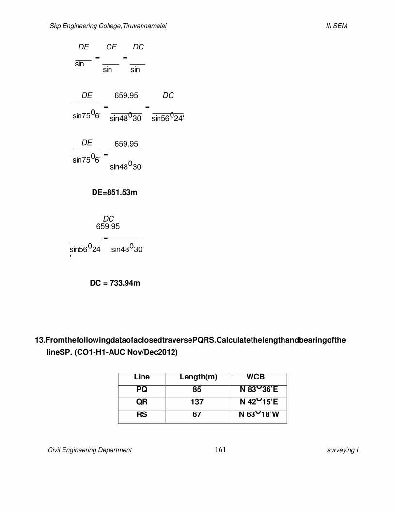
Skp Engineering College,Tiruvannamalai III SEM
Civil Engineering Department 161 surveying I
DE
sin
CE
=
sin
DC
=
sin
DE
sin7506'
DE
sin7506'
659.95
=
sin48030'
659.95
=
sin48030'
DC
=
sin56024'
DE=851.53m
DC 659.95
=
sin56024'
sin48030'
DC = 733.94m
13.FromthefollowingdataofaclosedtraversePQRS.Calculatethelengthandbearingofthe
lineSP. (CO1-H1-AUC Nov/Dec2012)
Line Length(m) WCB
PQ 85 N 83O36’E
QR 137 N 42O15’E
RS 67 N 63O18’W

Skp Engineering College,Tiruvannamalai III SEM
Civil Engineering Department 162 surveying I
Solution:
Line
Latitude Departure
+ - + -
PQ 9.47 84.47
QR 101.41 92.11
RS 30.10 59.85
Sum 140.98 176.58 59.85
∑LI= 140.98 ∑DI= 116.73
LatitudeofSP = - ∑LI =- 140.98m
DepartureofSP= - ∑DI=-116.73m
Sincelatitude anddepartureofSP isnegative. It lies inSWquadrant.
Thereducedbearing of SP (θ) is
tanθ=
Departur
e
Latitude
116.73
=
140.98
=0.827
θ= tan-1(0.827)

Skp Engineering College,Tiruvannamalai III SEM
Civil Engineering Department 163 surveying I
Bearing ofSP, θ = S 39o35’W= 219o35’
Length ofSP=
Latitude
=
cos
140.98
cos(39035
')
=182.92 m
Length of SP=182.92 m
14.Explaintheanglemeasuring proceduresusingtheodolite. (CO1-H1-AUC
May/June 2013)
Theinstrumentsusedtomeasuretheangles are Transit theodolite,Tripodand
Ranging rods(2no.s).
Thefollowingproceduresareusedtofindtheangles,
Setuptheinstrumentover‘O’and level itaccurately.
Withthehelp of upper clampandtangent screw, set0º readingonvernier‘A’.Notethe
readingofvernier‘B’.
Release theupper clampand direct thetelescopeapproximatelytowardsthepoint‘P’.
Tightenthelowerclampand bisect point‘P’ accuratelybylowertangent screw.
The image part with relationship ID
rId104 was not found i…
The image part with relationship ID rId105 was not found i…
The image part with
relationship ID rId106 was not found i…
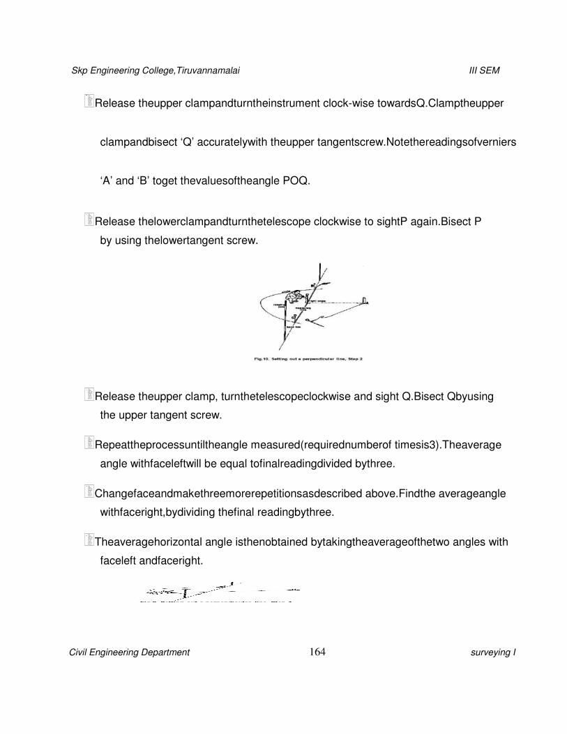
Skp Engineering College,Tiruvannamalai III SEM
Civil Engineering Department 164 surveying I
Release theupper clampandturntheinstrument clock-wise towardsQ.Clamptheupper
clampandbisect ‘Q’ accuratelywith theupper tangentscrew.Notethereadingsofverniers
‘A’ and ‘B’ toget thevaluesoftheangle POQ.
Release thelowerclampandturnthetelescope clockwise to sightP again.Bisect P
by using thelowertangent screw.
Release theupper clamp, turnthetelescopeclockwise and sight Q.Bisect Qbyusing
the upper tangent screw.
Repeattheprocessuntiltheangle measured(requirednumberof timesis3).Theaverage
angle withfaceleftwill be equal tofinalreadingdivided bythree.
Changefaceandmakethreemorerepetitionsasdescribed above.Findthe averageangle
withfaceright,bydividing thefinal readingbythree.
Theaveragehorizontal angle isthenobtained bytakingtheaverageofthetwo angles with
faceleft andfaceright.
The image part with relationship ID rId107 was not found i…
The image
part with relationship ID rId108 was not found i…
The image part with relationship ID rId110 was not found i…
The image part with relations
hip ID rId111 was not found i…
The image part with relationship ID rId112 was not found i…
The image part with relationship ID
rId113 was not found i…
Skp Engineering College,Tiruvannamalai III SEM
Civil Engineering Department 165 surveying I
15.ExplainBowditchrulewith example. (CO1-H1-AUC
May/June 2013)
The basisofthis method ison the assumptions that the errorsin linear measurementsare
proportionalto l where listhelengthofaline.TheBowditch’sruleisalsotermedasthe
compassrule.Itismostlyusedtobalanceatraversewherelinearandangularmeasurementsare
equalprecision.Thetotalerrorinlatitudeandinthedepartureisdistributedinproportiontothe
lengthsof thesides.
Bowditch Ruleis
Correctiontolatitude (ordeparture)ofanyside
=Total error inlatitude(ordeparture)X
Thusif CL = Correctiontolatitudeofanyside
CD= Correctiontodepartureofanyside
∑L= total error in latitude
∑D= total errorin departure
∑l= lengthof the perimeter
l= lengthofanyside
Lengthofthatside
perimeteroftravers
e

S.K.P. Engineering College, Tiruvannamalai III SEM
Civil Engineering Department 166 Surveying I