sketchup 8 for interior designers - sdc · pdf filesketchup 8 for interior designers | 39...
TRANSCRIPT

SketchUp 8 for Interior DesignersStudio CompanionJust the Basics
www.SDCpublications.comBetter Textbooks. Lower Prices.SDC
P U B L I C A T I O N S
Schroff Development Corporation
®
Daniel John Stine

Visit the following websites to learn more about this book:
SketchUp 8 for Interior Designers | 39
Section 6
The Basic Entities
Given the amazing images one can create using SketchUp, it may be somewhat surprising that there
are mainly eight types of entities which can be added to a model.
They are:
• Edges
• Surfaces
• Annotation o Dimensions o Text o 3D Text
• Components
• Groups
• Guide (reference line)
The next few pages will provide a brief overview of each of these entity types.
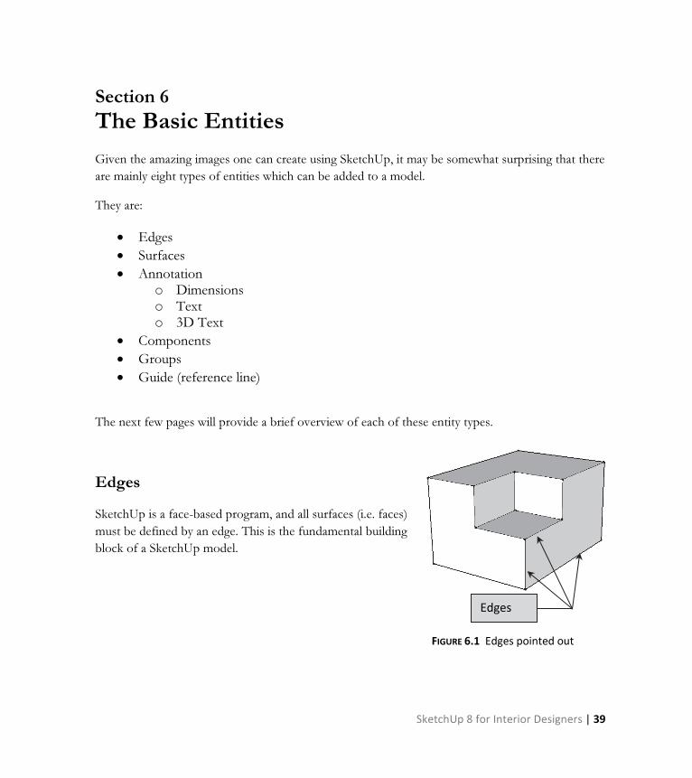
Edges
SketchUp is a face-based program, and all surfaces (i.e. faces)
must be defined by an edge. This is the fundamental building
block of a SketchUp model.
FIGURE 6.1 Edges pointed out
Edges
40 | SketchUp 8 for Interior Designers
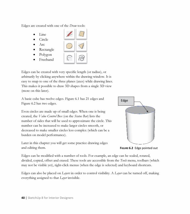
Edges are created with one of the Draw tools:
• Line
• Circle
• Arc
• Rectangle
• Polygon
• Freehand
Edges can be created with very specific length (or radius), or
arbitrarily by clicking anywhere within the drawing window. It is
easy to snap to one of the three planes (axes) while drawing lines.
This makes it possible to draw 3D shapes from a single 3D view
A basic cube has twelve edges. Figure 6.1 has 21 edges and
Figure 6.2 has two edges.
Even circles are made up of small edges. When one is being
created, the Value Control Box (on the Status Bar) lists the
number of sides that will be used to approximate the circle. This
number can be increased to make larger circles smooth, or
decreased to make smaller circles less complex (which can be a
burden on model performance).
Later in this chapter you will get some practice drawing edges
and editing them.
Edges can be modified with a number of tools. For example, an edge can be scaled, rotated,
divided, copied, offset and erased. These tools are accessible from the Tools menu, toolbars (which
may not be visible yet), right-click menus (when the edge is selected) and keyboard shortcuts.
Edges can also be placed on Layers in order to control visibility. A Layer can be turned off, making
everything assigned to that Layer invisible.
Edge
FIGURE 6.2 Edge pointed out

SketchUp 8 for Interior Designers | 41
Surfaces
A surface is the second most significant type of entity in SketchUp.
You might be surprised to learn that no tool exists to create a
surface! They are created automatically when the conditions are right.
What are the conditions in which a surface is automatically created?
The simple answer is that a series of edges forms an enclosed
area. When the last edge is drawn which defines an enclosed area, a
surface is created. This can be as few as three edges – forming a
triangle.
The image to the right (Figure 6.3) shows two examples of three
connected edges defining a surface. Note the edges can be a
combination of straight and curved lines.
If an edge is erased, the surface is also erased, seeing as it no longer has a boundary.
In addition to edges forming a closed perimeter, there is another important requirement a new
modeler needs to be aware of; that is, all the lines forming the enclosure must be coplanar.
FIGURE 6.3
Surfaces defined by at least
three edges
Surface
Project Example Image courtesy of LHB; www.LHBcorp.com

42 | SketchUp 8 for Interior Designers
If you don’t already know, the easiest way to describe coplanar is
to think of all the edges as lines drawn on a flat piece of paper.
As long as all the lines are in the same plane (i.e., on that flat
piece of paper) a surface will be created.
Surfaces may have materials painted on them. They can also be
placed on Layers in order to control visibility.
A surface can be deleted; simply select it and
press the Delete key on the keyboard. The only
way to get another surface is to draw a line
directly on top of one of the existing edges.
SketchUp will then create a surface and delete
the extra line, as it does not allow two lines to
exist directly on top of each other.
Dimensions
Dimensions can be added to your SketchUp model. These are smart entities; they are not sketched
lines and manually entered text. A dimension entity becomes a permanent part of the model, unlike
the Tape Measure tool (which is used to list distances without drawing anything).
To place a dimension you simply pick three points; the first two are what you want to dimension
and the third is the location of the dimension line and text. SketchUp automatically displays the
correct length.
The dimensions are associative, relative to the first two points picked. The dimension will grow or
shrink if the geometry is modified. However, if the geometry is deleted the dimension will remain
(but is no longer associated to anything).
FIGURE 6.4
Coplanar on left, not on right
FIGURE 6.5 Another angle of Figure 6.4
SketchUp 8 for Interior Designers | 43
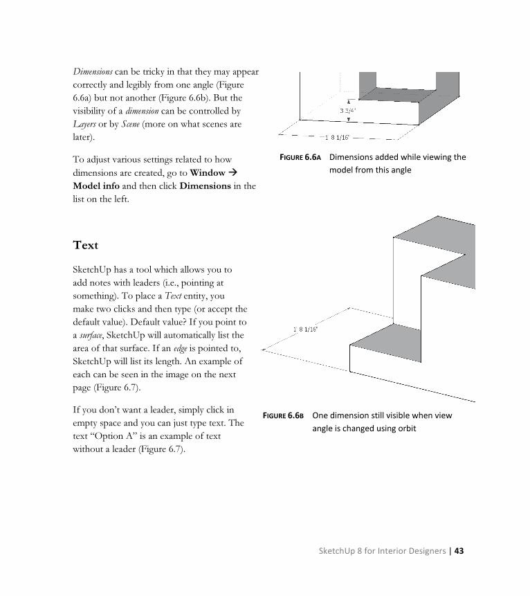
Dimensions can be tricky in that they may appear
correctly and legibly from one angle (Figure
6.6a) but not another (Figure 6.6b). But the
visibility of a dimension can be controlled by
Layers or by Scene (more on what scenes are
later).
To adjust various settings related to how
dimensions are created, go to Window �
Model info and then click Dimensions in the
list on the left.
Text
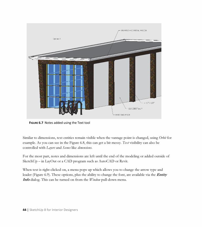
SketchUp has a tool which allows you to
add notes with leaders (i.e., pointing at
something). To place a Text entity, you
make two clicks and then type (or accept the
default value). Default value? If you point to
a surface, SketchUp will automatically list the
area of that surface. If an edge is pointed to,
SketchUp will list its length. An example of
each can be seen in the image on the next
page (Figure 6.7).
If you don’t want a leader, simply click in
empty space and you can just type text. The
text “Option A” is an example of text
without a leader (Figure 6.7).
FIGURE 6.6A Dimensions added while viewing the
model from this angle
FIGURE 6.6B One dimension still visible when view
angle is changed using orbit
44 | SketchUp 8 for Interior Designers
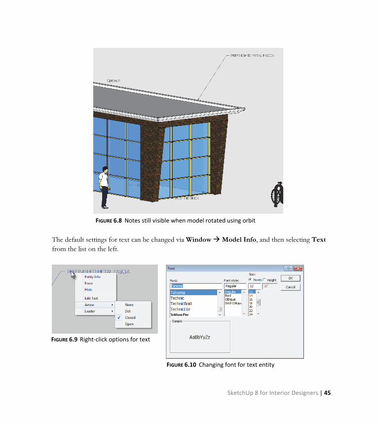
Similar to dimensions, text entities remain visible when the vantage point is changed, using Orbit for
example. As you can see in the Figure 6.8, this can get a bit messy. Text visibility can also be
controlled with Layers and Scenes like dimensions.
For the most part, notes and dimensions are left until the end of the modeling or added outside of
SketchUp – in LayOut or a CAD program such as AutoCAD or Revit.
When text is right-clicked on, a menu pops up which allows you to change the arrow type and
leader (Figure 6.9). These options, plus the ability to change the font, are available via the Entity
Info dialog. This can be turned on from the Window pull-down menu.
FIGURE 6.7 Notes added using the Text tool
SketchUp 8 for Interior Designers | 45
The default settings for text can be changed via Window � Model Info, and then selecting Text
from the list on the left.
FIGURE 6.8 Notes still visible when model rotated using orbit
FIGURE 6.9 Right-click options for text
FIGURE 6.10 Changing font for text entity

46 | SketchUp 8 for Interior Designers
3D Text
The Text tool, just covered, is meant for notes and
comments about the model. 3D Text is meant to be part of
the model. This tool is used to model text on signs or
letters on the face of a building. Unlike notes created with
the Text tool, 3D Text stays right where you put it.
Placing 3D Text is easy. Select the tool, and the Place 3D
Text dialog appears (Figure 6.11). Enter your text and
select the options desired for font style, height and
thickness (i.e., extruded). Click OK and then pick a
location on a face to place it.
Once the 3D Text is placed, the Paint Bucket tool can be
used to apply a material.
FIGURE 6.12 3D Text placed
FIGURE 6.11 Adding 3D Text

SketchUp 8 for Interior Designers | 47
Once the text is created, it becomes a Component that
cannot be easily edited (in terms of typing new words).
It is possible to see the properties for 3D Text, or
anything else selected, using the Entity Info dialog
(Figure 6.13). This can be turned on from the Window
pull-down menu. The information presented varies
depending on what is selected. This dialog can remain
open while modeling.
Components
In SketchUp one can think of
Components being something like
clipart in a word processing program
– but clipart on steroids! They are
pre-built models which can be reused
in your SketchUp model. Some
Components are flat 2D models while
others are complex 3D models. The
simple, flat Components reduce the
resources required of your computer,
making it easier to smoothly orbit
and inspect your model. For example,
many of the trees which designers use
in SketchUp are 2D due to the
number typically needed. If 3D trees
were used, the file would be large and
unmanageable. The 2D Components
can be setup so that they always face
you – plus they cast shadows (see
Figures 6.14 and 6.15).
FIGURE 6.13 Entity Info dialog
Image courtesy of LHB; www.LHBcorp.com

48 | SketchUp 8 for Interior Designers
Right-clicking on a Component allows you to edit
it, explode it (reduce it down to individual
entities) and add parameters and parametrics
using the advanced Dynamic Components
functionality.
Editing a Component causes all instances of that
Component, in your model, to instantly update.
You will see an example of this in the next
section.
FIGURE 6.14 2D vs. 3D components; two items are 2D and two are 3D.
FIGURE 6.15 Rotated view of previous image
SketchUp 8 for Interior Designers | 49
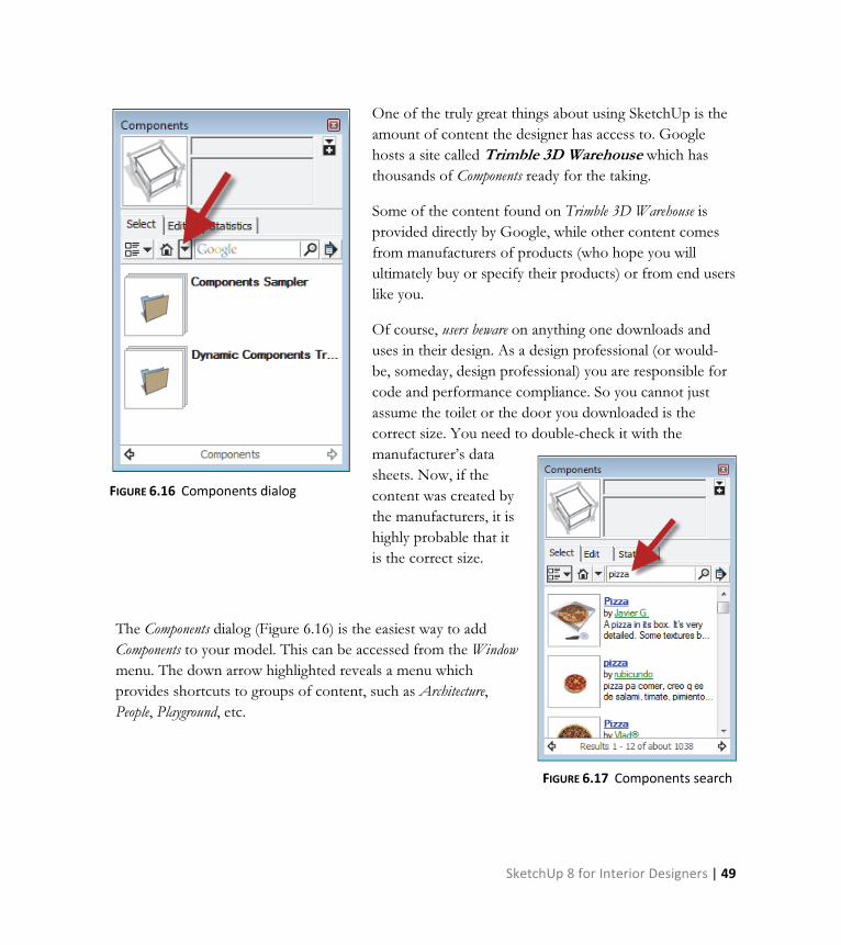
One of the truly great things about using SketchUp is the
amount of content the designer has access to. Google
hosts a site called Trimble 3D Warehouse which has
thousands of Components ready for the taking.
Some of the content found on Trimble 3D Warehouse is
provided directly by Google, while other content comes
from manufacturers of products (who hope you will
ultimately buy or specify their products) or from end users
like you.
Of course, users beware on anything one downloads and
uses in their design. As a design professional (or would-
be, someday, design professional) you are responsible for
code and performance compliance. So you cannot just
assume the toilet or the door you downloaded is the
correct size. You need to double-check it with the
manufacturer’s data
sheets. Now, if the
content was created by
the manufacturers, it is
highly probable that it
is the correct size.
The Components dialog (Figure 6.16) is the easiest way to add
Components to your model. This can be accessed from the Window
menu. The down arrow highlighted reveals a menu which
provides shortcuts to groups of content, such as Architecture,
People, Playground, etc.
FIGURE 6.16 Components dialog
FIGURE 6.17 Components search

50 | SketchUp 8 for Interior Designers
It is also possible to search for Components. You may be surprised at what you can find. Figure 6.17
shows some of the results when searching for “pizza”! Notice the author of the component is
listed directly under the name.
Try a few searches to see what you can find – maybe try goat, newspaper, or snowboard.
See the next section for more on Components.
Groups
A Group is similar to a Component in that you can select one part of it and the entire representation is
selected (selecting potentially hundreds of entities with a single pick). However, that is about all that
is the same between them.
Groups are meant for one-off type items; that is, a unique reception desk,
a built-in entertainment center, etc. A Component is used when your model
will contain many instances of an object.
Both Groups and Components are easy to create. You simply model
something, select it and then right-click (on it). At this point you can
select either Make Group or Make Component (Figure 6.18).
Both Groups and Components can be copied around the model (using the
Move tool and holding down Ctrl). They both can also be edited, by right-
clicking and selecting “edit” from the pop-up menu.
It is important to note that editing a Group only changes the specific
Group you are editing. But editing a Component instantly causes all
instances of that Component to update (see Figures 6.20 and 6.21). This
means SketchUp duplicates all information required to define each copy
of a Group. A single definition is all that is needed for multiple instances
of a Component. Of course, this means a file with many copies of a Group
will be larger than one with many copies of a Component.
FIGURE 6.18 Right-click
menu

SketchUp 8 for Interior Designers | 51
The main thing to keep in mind is that Groups are quick and require minimal decisions. Components
can be much more sophisticated and take a lot of time setting up (creating parameters and
parametric relationships, and adding formulas).
When you right-click and select Make Group, SketchUp
just makes it without asking any questions. It can be
selected and named via the Entity Info dialog if you wish.
When creating a Component, the Create Component dialog
appears (Figure 6.19). Notice the various options:
• Glue to – does the tree stick to the ground or float in the air?
• Always face the camera – this is ideal for flat two-dimensional items.
• Replace selection – turn the current selection into one of the Components you are creating.
The images below compare what happens
when a Component is edited versus a Group.
Notice all instances of the Component are
updated, whereas only the selected Group
being edited is updated (even though the other
Groups are copies of the one being edited).
FIGURE 6.19 Right-click menu
Image courtesy of LHB; www.LHBcorp.com

52 | SketchUp 8 for Interior Designers
FIGURE 6.20 Components vs. Groups – Components on the left; Groups on the right

SketchUp 8 for Interior Designers | 53
FIGURE 6.21 Components vs. Groups – all Components update; only selected Group updates
54 | SketchUp 8 for Interior Designers
Guides
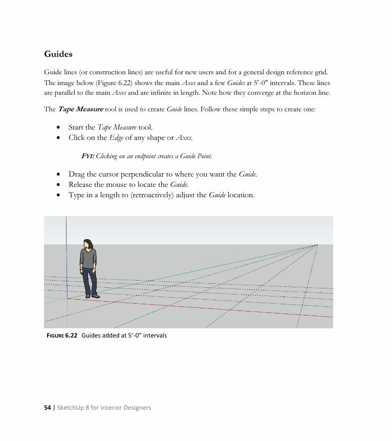
Guide lines (or construction lines) are useful for new users and for a general design reference grid.
The image below (Figure 6.22) shows the main Axes and a few Guides at 5′-0″ intervals. These lines
are parallel to the main Axes and are infinite in length. Note how they converge at the horizon line.
The Tape Measure tool is used to create Guide lines. Follow these simple steps to create one:
• Start the Tape Measure tool.
• Click on the Edge of any shape or Axes.
FYI: Clicking on an endpoint creates a Guide Point.
• Drag the cursor perpendicular to where you want the Guide.
• Release the mouse to locate the Guide.
• Type in a length to (retroactively) adjust the Guide location.
FIGURE 6.22 Guides added at 5′-0″ intervals
SketchUp 8 for Interior Designers | 55
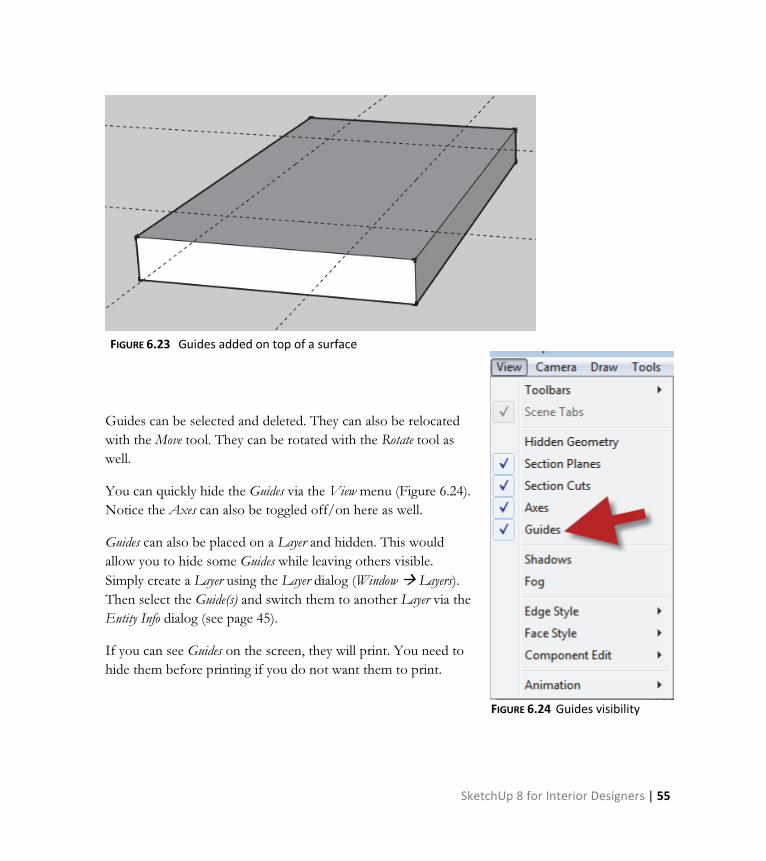
Guides can be selected and deleted. They can also be relocated
with the Move tool. They can be rotated with the Rotate tool as
well.
You can quickly hide the Guides via the View menu (Figure 6.24).
Notice the Axes can also be toggled off/on here as well.
Guides can also be placed on a Layer and hidden. This would
allow you to hide some Guides while leaving others visible.
Simply create a Layer using the Layer dialog (Window � Layers).
Then select the Guide(s) and switch them to another Layer via the
Entity Info dialog (see page 45).
If you can see Guides on the screen, they will print. You need to
hide them before printing if you do not want them to print.
FIGURE 6.23 Guides added on top of a surface
FIGURE 6.24 Guides visibility
56 | SketchUp 8 for Interior Designers
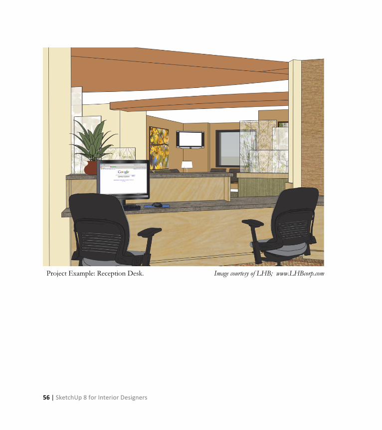
Project Example: Reception Desk. Image courtesy of LHB; www.LHBcorp.com