sk rs general manual for craftsman permanently …€¦ · remain closed. on the upstroke of the...
TRANSCRIPT
SK RSCRAFTSMAN
NOTE: For identification of Re-
pair Parts, see separate PartsList Manual.
IMPORTANT:Read the Safety Guidelinesand All InstructionsCarefully Before Operating
GENERAL MANUAL FOR
PERMANENTLY LUBRICATEDTANK MOUNTED
AIR COMPRESSOR
SAFETY GUIDELINESASSEMBLYOPERATION
MAINTENANCETROUBLESHOOTINGREPAIR PARTS
Record in the spaces provided.(1) The model number which can be
found on the maintenance label onthe top of the motor coveror on thetank.
(2) The code number which can befound on the foil label onthe rear ofthe air tank.
(3) The Manufacturers Number is lo-cated onthe metal data platewhichis welded onto the backside of theair tank. (This data plate is paintedthe same color as the tank.)
Retain these numbers for futurereference.
Model No.
Code No.
I Mfg. No.
MG-OILFREE 1/20/94 I
Sears, Roebuck and Co., Chicago, IL 60684 U.S.A.
TABLE OF CONTENTS
Page
WARRANTY .......................................................................................................................................... 2
SAFETY GUIDELINES ......................................................................................................................... 3
WARNING CHART ............................................................................................................................... 3
GLOSSARY ........................................................................................................................................... 5
ACCESSORIES FOR USE WITH SEARS AIR COMPRESSORS .................................................. 5
GENERAL INFORMATION .................................................................................................................. 5
DESCRIPTION OF OPERATION ....................................................................................................... 6
ASSEMBLY ........................................................................................................................................... 7
INSTALLATION AND BREAK-IN PROCEDURES ............................................................................ 7Location of Air Compressor ........................................................................................................... 7Lubrication and Oil ......................................................................................................................... 7Extension Cords ............................................................................................................................. 7Voltage and Circuit Protection ....................................................................................................... 7Grounding Instructions ................................................................................................................... 8Break-in Procedure ........................................................................................................................ 8
OPERATING PROCEDURES ............................................................................................................. 9
MAINTENANCE .................................................................................................................................. 10Air Filter - Inspection and Replacement ..................................................................................... 10Check Valve -Replacement ......................................................................................................... 10Safety Valve - Inspection ............................................................................................................. 10Motor ............................................................................................................................................. 10Storage .......................................................................................................................................... 10
TROUBLESHOOTING GUIDE .......................................................................................................... 11
HOW TO ORDER REPAIR PARTS .................................................................................................. 16
FULL ONE YEAR WARRANTY ON AIR COMPRESSORS
tf this air compressor fails due to a defect in material or workmanship within one year from the date of purchase, RETURNITTO THE NEAREST SEARS SERVICE CENTER/DEPARTMENT THROUGHOUT THE UNITED STATES AND SEARSWILL REPAIR IT, FREE OF CHARGE.
If this air compressoris used for commercialor rental purposes, the warranty will apply for ninety days from the date ofpurchase.
This warrantygives you specific legal rights and you may have other rights which vary from state to state.
Sears, Roebuck and Co., Sears Tower, Dept. 731CR-W, Chicago, IL 60684
SAFETY GUIDELINES
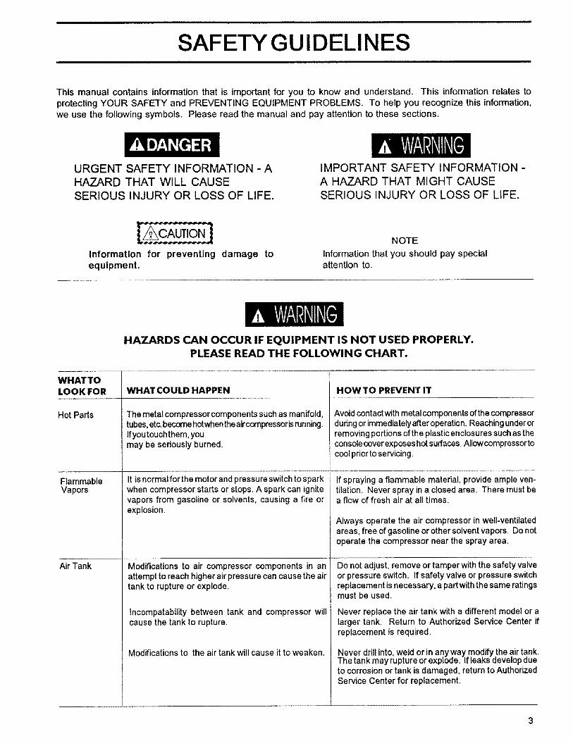
This manual contains information that is important for you to know and understand. This information relates toprotecting YOUR SAFETY and PREVENTING EQUIPMENT PROBLEMS. To help you recognize this information,we use the following symbols. Please read the manual and pay attention to these sections.
URGENT SAFETY INFORMATION - AHAZARD THAT WILL CAUSE
SERIOUS INJURY OR LOSS OF LIFE.
IMPORTANT SAFETY INFORMATION -A HAZARD THAT MIGHT CAUSE
SERIOUS INJURY OR LOSS OF LIFE.
Information for preventing damage toequipment.
NOTE
Information that you should pay specialattention to.
WHAT TOLOOK FOR
Hot Parts
FlammableVapors
Air Tank
HAZARDS CAN OCCUR IF EQUIPMENT IS NOT USED PROPERLY.PLEASE READ THE FOLLOWING CHART.
WHAT COULD HAPPEN
The metalcompressor components such as manifold,tubes,etc,becomehotwhentheaircompressorisrunning.Ifyoutouchthem, youmay be seriously burned.
It is normal for the motor and pressure switch to sparkwhen compressor starts or stops. A spark can ignitevapors from gasoline or solvents, causing a fire orexplosion.
Modifications to air compressor components in anattempt to reach higher air pressure can cause the airtank to rupture or explode.
Incomparability between tank and compressor willcause the tank to rupture.
Modifications to the air tank will cause it to weaken.
HOW TO PREVENT IT
Avoid contact withmetal components of the compressorduring or immediately after operation. Reaching under orremoving portions of the plastic enclosures such as theconsole cover exposes hot surfaces. Allowcompressortocool prior to servicing.
If spraying a flammable material, provide ample ven-tilation. Never spray in a closed area. There must bea flow of fresh air at all times.
Always operate the air compressor in well-ventilatedareas, free of gasoline or other solvent vapors. Do notoperate the compressor near the spray area.
Do not adjust, remove or tamper with the safety valveor pressure switch. If safety valve or pressure switchreplacement is necessary, a part with the same ratingsmust be used.
Never replace the air tank with a different model or alarger tank. Return to Authorized Service Center ifreplacement is required.
Never drill into weldor in anyway modify theair tank.The tank may rupture or explode. If leaks deve op dueto corrosion or tank is damaged, return to AuthorizedService Center for replacement.
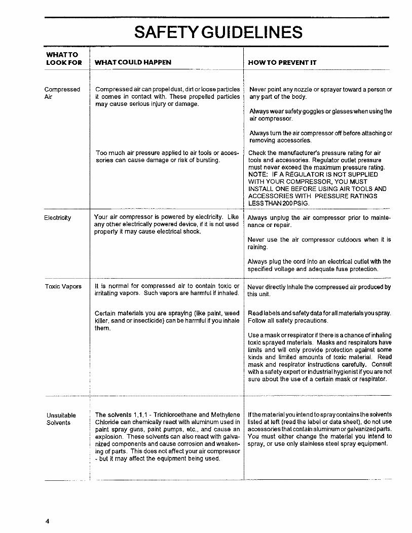
SAFETY GUIDELINES
WHAT TOLOOK FOR WHAT COULD HAPPEN HOW TO PREVENT IT
CompressedAir
Electricity
Toxic Vapors
UnsuitableSolvents
Compressed air can propel dust, dirt or loose particlesit comes in contact with. These propelled particlesmay cause serious injury or damage.
Too much air pressure applied to air tools or acces-sories can cause damage or risk of bursting.
Your air compressor is powered by electricity. Likeany other electrically powered device, if it is not usedproperly it may cause electrical shock,
It is normal for compressed air to contain toxic orirritating vapors, Such vapors are harmful if inhaled.
Certain materials you are spraying (like paint, weedkiller, sand or insecticide) can be harmful if you inhalethem.
The solvents 1,1,1 - Trichloroethane and MethyleneChloride can chemically react with aluminum used inpaint spray guns, paint pumps, etc., and cause anexplosion. These solvents can also react with galva-nized components and cause corrosion and weaken-ing of parts. This does not affect your air compressor- but it may affect the equipment being used.
Never point any nozzle or sprayer toward a personorany part of the body.
Always wear safetygoggles or glasses when usingtheair compressor.
Always turn the aircompressoroff before attachingorremoving accessories.
Check the manufacturer's pressure rating for airtools and accessories. Regulator outlet pressuremust never exceed the maximum pressure rating.NOTE: IF A REGULATOR IS NOT SUPPLIED
WITH YOUR COMPRESSOR, YOU MUSTINSTALL ONE BEFORE USING AIR TOOLS ANDACCESSORIES WITH PRESSURE RATINGSLESS THAN 200 PSIG.
Always unplug the air compressor prior to mainte-nance or repair.
Never use the air compressor outdoors when it israining.
Always plug the cord into an electrical outlet with thespecified voltage and adequate fuse protection.
Never directly inhale the compressed air produced bythis unit.
Read labels and safety data for allmaterials you spray.Follow all safety precautions.
Use amask or respirator if there is a chance of inhalingtoxic sprayed materials. Masks and respirators havelimits and will only provide protection against somekinds and limited amounts of toxic material. Readmask and respirator instructions carefully. Consultwith asafety expert or industrial hygienist ifyou arenotsure about the use of a certain mask or respirator.
If the material you intend to spray contains the solventslisted at left (read the label or data sheet), do not useaccessories that contain aluminum or galvanized pads.You must either change the material you intend tospray, or use only stainless steel spray equipment.
GLOSSARY
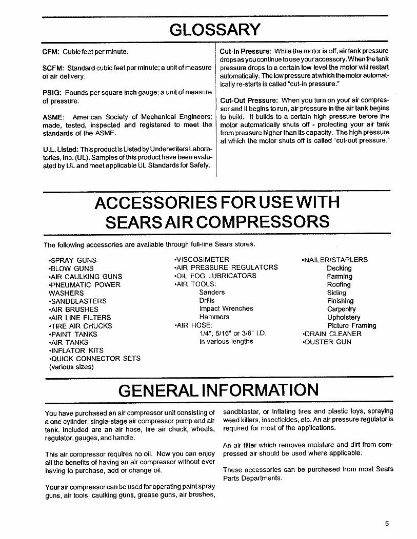
CFM: Cubicfeet per minute.
SCFM: Standard cubic feet per minute; a unit of measureof air delivery.
PSlG: Pounds per square inch gauge; a unit of measureof pressure.
ASME: American Society of Mechanical Engineers;made, tested, inspected and registered to meet thestandards of the ASME.
U.L. Listed: This productis Listed by Underwriters Labora-tories, Inc. (UL). Samples of this product have been evalu-ated by UL and meet applicable UL Standards for Safety.
Cut-In Pressure: While the motor is off, air tank pressuredrops as you continue to use youraccessory.When the tankpressure drops to a certain low level the motor will restartautomatically. The low pressure atwhich the motor automat-ically re-starts is called "cut-in pressure."
Cut-Out Pressure: When you turn on your air compres-sor and it begins to run, air pressure in the air tank beginsto build. It builds to a certain high pressure before themotor automatically shuts off - protecting your air tankfrom pressure higher than its capacity. The high pressureat which the motor shuts off is called "cut-out pressure."
ACCESSORIES FOR USE WITHSEARS AIR COMPRESSORS
The following accessories are available through full-line Sears stores.
•SPRAY GUNS•BLOW GUNS•AIR CAULKING GUNS-PNEUMATIC POWERWASH ERS.SANDBLASTERS-AIR BRUSHES•AIR LINE FILTERS•TIRE AIR CHUCKS•PAINT TANKS•AIR TANKS• INFLATOR KITS•QUICK CONNECTOR SETS(various sizes)
.VISCOSIMETER*AIR PRESSURE REGULATORS•OIL FOG LUBRICATORS•AIR TOOLS:
SandersDrillsImpact WrenchesHammers
•AIR HOSE:1/4", 5/16" or 3/8" I.D.in various lengths
*NAILER/STAPLERSDeckingFarmingRoofingSidingFinishingCarpentryUpholsteryPicture Framing
•DRAIN CLEANER•DUSTER GUN
GENERAL INFORMATION
You have purchased an air compressor unit consisting ofa one cylinder, single-stage air compressor pump and airtank. Included are an air hose, tire air chuck, wheels,regulator, gauges, and handle.
This air compressor requires no oil. Now you can enjoyall the benefits of having an air compressor without everhaving to purchase, add or change oil.
Your air compressor can be used for operating paint sprayguns, air tools, caulking guns, grease guns, air brushes,
sandblaster, or inflating tires and plastic toys, sprayingweed killers, insecticides, etc. An air pressure regulator isrequired for most of the applications.
An air filter which removes moisture and dirt from com-pressed air should be used where applicable.
These accessories can be purchased from most SearsParts Departments.
DESCRIPTION OF OPERATION
Air Compressor Pump: To compress air, the pistonmoves up and down inthe cylinder. On the downstroke, airisdrawn inthrough the air intake valves. The exhaust valvesremain closed. On the upstroke of the piston, air iscompressed. The intake valves closeandcompressed air isforced out through the exhaust valves, through the outlettube, throughthe checkvalve and intothe air tank. Workingair is not available until the compressor has raised the airtank pressure above that required at the air outlet.
Check Valve: When the air compressor is operating, thecheck valve is "open", allowing compressed air to enterthe air tank. When the air compressor reaches "cut-out"pressure, the check valve "closes", allowing air pressureto remain inside the air tank.
Pressure ReleaseValve: The pressure release valve locatedon the side of the pressure switch, is designed to automat-icallyrelease compressed air from the compressorhead andthe outlet tube when the air compressor reaches "cut-out"pressure or is shut off. If the air is not released, the motorwill not be able to start. The pressure release valve allowsthe motor to restart freely. When the mQtor stopsrunning,air willbe heard escaping from the valve for a few seconds.No air should be leaking when the motor is running.
Pressure Switch: The pressure switchautomatically startsthemotorwhen the air tank pressure drops belowthe factoryset "cut-in" pressure. It stops the motor when the air tankpressure reaches the factory set "cut-out" pressure.
SafetyValve: Ifthe pressure switch does notshutoffthe aircompressor at itscut-out pressure setting,the safety valvewill protect the tank against high pressure by =popping out"at itsfactory set pressure (slightlyhigher than the pressureswitchcut-out setting).
Regulator: The air pressure coming from the air tank iscontrolled by the regulator. Turn the regulator knob clock-wise to increase pressure and counter-clockwise to de-crease pressure. To avoid minor readjustment aftermaking a change in pressure setting, always approachthe desired pressure from a lower pressure. Whenreducing from a higher to a lower setting, first reduce tosome pressure less than that desired, then bring up to thedesired pressure. Depending on the air requirements ofeach particular accessory, the outlet regulated air pres-sure may have to be adjusted while operating the acces-sory.
Outlet Pressure Gauge: The outlet pressure gauge indi-cates the air pressure available at the outlet side of theregulator. This pressure is controlled by the regulatorandis always less or equal to the tank pressure. See"Operating Procedures".
Tank Pressure Gauge: The tank pressure gauge indicatesthe reserve air pressure inthe tank.
Cooling System: This compressor contains an advanceddesign cooling system.At the heartofthis coolingsystem isan engineered fan. It is perfectly normal for this fan to blowair through the vent holes inlarge amounts. You know thatthe cooling system is working when air is being expelled.
Tools Needed for Assembly
• a 9/16" socket or open end wrench for attaching the wheels• a 3/8" open end wrench or socket to tighten handle screws
ASSEMBLY
Installing Wheels, Handles, Rubber
Foot Strip
THE WHEELS AND HANDLE DO NOT PRO-VIDE ADEQUATE CLEARANCE, STABILITYOR SUPPORT FOR PULLING THE UNIT UPAND DOWN STAIRS OR STEPS. THE UNITMUSTBE LIFTED, ORPUSHED UPARAMP.
Attach the handle to the compressor saddle by insertingthe handle inside the compressor saddle and lining upthe two bolt holes on each side. Install the four screws,two on each side. Tighten securely.
.
It will be necessary to brace or support one sideof the outfit when installing thewheels becausethe compressorwlll have a tendency to tip.
Install one shoulder bolt and one nut for each wheel
using lower bolt hole for 12 gallon units and upper bolthole for 25 gallon units.
.
Tighten securely. The outfit will sit level if the wheelsare properly installed.
Clean and dry underside of air tank leg oppositewheels. Remove the protective paper strip from theadhesive backed rubber foot strip. Attach the rubberfoot strip to the bottom of leg. Press firmly into place.
Removing Shipping Boards and InstallingRubber Feet
It will be necessary to brace or support one sideof the outfit when removing the shipping boardsand installing rubber feet because the air com-pressor will have a tendency to tip.
.
,
Using the 9/16 wrench, remove the four screws hold-ing the shipping boards in place. Save these screws.
Using the same screws, install the rubber feet suppliedwith the compressor.
INSTALLATION AND BREAK-IN PROCEDURES
If an extension cord must be used, be sure it is:
Location of the Air Compressor
Locate the air compressor in a clean, dry and wellventilated area. The air filter must be kept clear ofobstructions which could reduce air delivery of the aircompressor. The air compressor should be located atleast 12" away from the wall or other obstructions that willinterfere with the flow of air. The air compressor head andshroud are designed to allow for proper cooling.
Lubrication and Oil
This unit needs no lubrication or oiling.
Extension Cords
Use extra air hose instead of an extension cord to avoidvoltage drop and power loss to the motor, and to preventoverheating.
- a 3-wire extension cord that has a 3-blade groundingplug, and a 3-slot receptacle that will accept the plugon the product
• ingood condition
• no longer than 50 feet
• 12 gauge (AWG) or larger. (Wire size increases asgauge number decreases. 10 AWG and 8 AWG mayalso be used. DO NOT USE 14 OR 16 AWG.)
Voltage and Circuit Protection
Refer to your Parts List Manual for the voltage and circuitprotction requirements of your compressor. Use only afuse or circuit breaker that is the same rating as the branchcircuit the air compressor is operated on. If the compres-sor is connected to a circuit protcted by fuses, use onlydual element time delay fuses, as noted in that ServiceBulletin.
7
Referto Parts List Manual for your compressor. Certainair compressor models can be operated on a 15 ampcircuit if:
1. Voltage supply to circuit is normal.
2. Circuit is not used to supply any other electrical needs(lights, appliances, etc.).
3. Extension cords comply with specifications.
4. Circuit is equipped with a 15 amp circuit breaker or 15amp time delay fuse.
Ifany of the above conditions cannot be met, or if operationof the compressor repeatedly causes interruption of thepower, it may be necessary to operate it from a 20 ampcircuit. It is not necessary to change the cord set.
GROUNDING INSTRUCTIONS
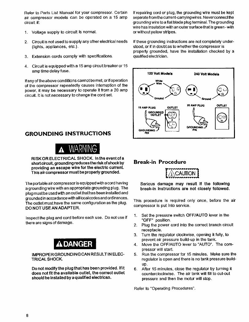
If repairing cord or plug, the grounding wire must be keptseparate from the current-carrying wires. Neverconnectthegrounding wire to a flat blade plug terminal. The groundingwire has insulation with an outer surface that is green- withor without yellow stripes.
If these grounding instructions are not completely under-stood, or if in doubt as to whether the compressor isproperly grounded, have the installation checked by aqualified electrician.
120 Volt Models 240 Volt Models
White
2O AMP PLUG OUTLET
GROUNDING J _ PINPIN
RISKOR ELECTRICAL SHOCK. In the event of ashort circuit, grounding reduces the risk of shock byproviding an escape wire for the electric current.This air compressor must be properly grounded.
The portable air com pressor is equipped with acord havinga grounding wire with an appropriate grounding plug. Theplug must be used with an outlet that has been installed andgrounded in accordance with all local codes and ordinances.The outlet must have the same configuration as the plug.DO NOT USE AN ADAPTER.
Inspect the plug and cord before each use. Do not use ifthere are signs of damage.
IMPROPER GROUNDING CAN RESULTIN ELEC-TRICAL SHOCK.
Do not modify the plug that has been provided. If itdoes not fit the available outlet, the correct outletshould be Installed by aqualified electrican.
Break-in Procedure
Serious damage may result if the followingbreak-in instructions are not closely followed.
This procedure is required only once, before the aircompressor is put into service.
1. Set the pressure switch OFF/AUTO lever in the"OFF" position.
2. Plug the power cord into the correct branch circuitreceptacle.
3. Turn the regulator clockwise, opening it fully, toprevent air pressure build-up in the tank.
4. Move the OFF/AUTO lever to "AUTO". The com-pressor will start.
5. Run the compressor for 15 minutes. Make sure theregulator is open and there is no tank pressure build-up.
6. After 15 minutes, close the regulator by turning itcounterclockwise. The air tank will fill to cut-outpressure and then the motor will stop.
Refer to "Operating Procedures".
OPERATING PROCEDURES
1. Before attaching air hose or accessories, make surethe OFF/AUTO lever is set to "OFF" and the air
regulator is closed.
2. Attach hose and accessories.
6. Always operate the air compressor in well-ventilated areas; free of gasoline or other solventvapors.
Do not operate the compressor near the sprayarea.
TOO MUCH AIR PRESSURE CREATESA HAZARDOUS RISK OF BURSTING.CAREFULLY FOLLOW STEPS 3 AND 5EACH TIME THE COMPRESSOR ISUSED.
Compressed air from the outfit may containwater condensation. Do not spray unfil-tered air at an item that could be damaged.Some air operated tools or devices mayrequire filtered air. Read the instructionsfor the air tool or device.
3. Check the manufacturer's maximum pressure rat-ing for air tools and accessories. The regulatoroutlet pressure must never exceed the maximumpressure rating. If your compressor is not suppliedwith a regulator with gauge, install one beforeusing accessories.
4. Turn the OFF/AUTO lever to "AUTO" and allow tankpressure to build. Motor will stop when tank pressurereaches "cut-out" pressure.
5. Open the regulator by turning it clockwise. Adjust theregulator to the correct pressure setting. Your com-pressor is ready for use.
When you are finished:7. Set the =OFF/AUTO" lever to "OFF".
8. Turn the regulator counterclockwise and set the out-let pressure to zero.
9. Remove the air tool or accessory.
10. Open the regulator and allow the air to slowly bleedfrom the tank. Close the regulator when tank pressureis approximately 20 psi.
11. Drain water from air tank.
WATER WILL CONDENSE IN THE AIR TANK.IF NOT DRAINED, WATER WILL CORRODEAND WEAKEN THE AIR TANK CAUSING ARISK OF AIR TANK RUPTURE.
With tank pressure at approximately 20 psi, open thedrain cock or drain valve.
NOTE:If drain cock valve is plugged, release all airpressure. The valve can then be removed,cleaned, then reinstalled.
12. After the water has been drained, closedrain cock or drain valve. The air compressorcan now be stored.
MAINTENANCE
UNIT CYCLES AUTOMATIOALLYWHEN POWER IS ON. WHEN DOING MAINTENANCE, YOU MAY BE EXPOSEDTO VOLTAGE SOURCES, COMPRESSEDAIROR MOVING PARTS. PERSONAL INJURIES CAN OCCUR. BEFOREPERFORMING ANY MAINTENANCE OR REPAIR, UNPLUG THE COMPRESSOR AND BLEED OFF ALL AIRPRESSURE.
ALL MAINTENANCE AND REPAIR OPERATIONS NOT LISTED MUST BE DONE BYQUALIFIED SERVICE PERSONNEL.
Air Filter- Inspection and Replacement 10. Replaceconsolecover.
Safety Valve - Inspection
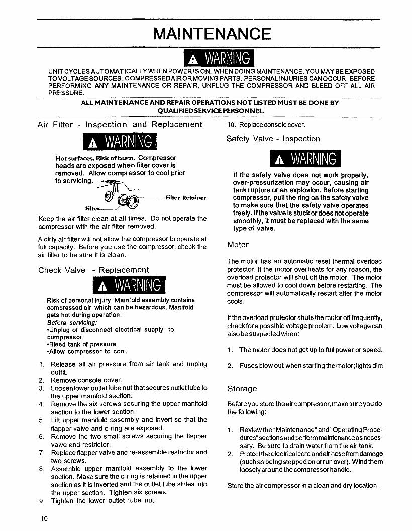
Hot surfaces. Risk of burn. Compressorheads are exposed when filter cover isremoved. Allow compressor to cool prior
to servicing. _ _Niter Retainer
NlteF
Keep the air filter clean at all times. Do not operate thecompressor with the air filter removed.
A dirty air filter will not allow the compressor to operate atfull capacity. Before you use the compressor, check theair filter to be sure it is clean.
Check Valve - Replacement
Risk of personal injury. Mainfold assembly containscompressed air which can be hazardous. Manifoldgets hot during operation.Before servicing:•Unplug or disconnect electrical supply tocompressor.-Bleed tank of pressure.•Allow compressor to cool.
1. Release al{ air pressure from air tank and unplugoutfit.
2. Remove console cover.3. Loosenlower outlettube nut thatsecures outlettubeto
the upper manifold section.4. Remove the six screws securing the upper manifold
section to the lower section.5. Lift upper manifold assembly and invert so that the
flapper valve and o-ring are exposed.6. Remove the two small screws securing the flapper
valve and restrictor.7. Replace flapper valve and re-assemble restrictor and
two screws.8. Assemble upper manifold assembly to the lower
section. Make sure the o-ring is retained in the uppersection as it is inverted and the outlet tube slides intothe upper section. Tighten six screws.
9. Tighten the lower outlet tube nut.
If the safety valve does not work properly,over-pressurization may occur, causing airtank rupture or an explosion. Before startingcompressor, pull the ring on the safety valveto make sure that the safety valve operatesfreely. If the valve Is stuckor does not operatesmoothly, it must be replaced with the sametype of valve.
Motor
The motor has an automatic reset thermal overload
protector. If the motor overheats for any reason, theoverload protector will shut off the motor. The motormust be allowed to cool down before restarting. Thecompressor will automatically restart after the motorCOOLS.
If the overload protector shuts the motor off frequently,check for a possible voltage problem. Low voltage canalso be suspected when:
1. The motor does not get up to full power or speed.
2. Fuses blow out when starting the motor; lights dim
Storage
Before you store theair compressor, make sure you dothe following:
1. Review the "Maintenance" and "Operating Proce-dures" sections and perform maintenance as neces-sary. Be sure to drain water from the air tank.
2. Protectthe electrical cord and air hose from damage(such as being stepped on or run over). Wind themloosely around the compressor handle.
Store the air compressor in a clean and dry location.
10
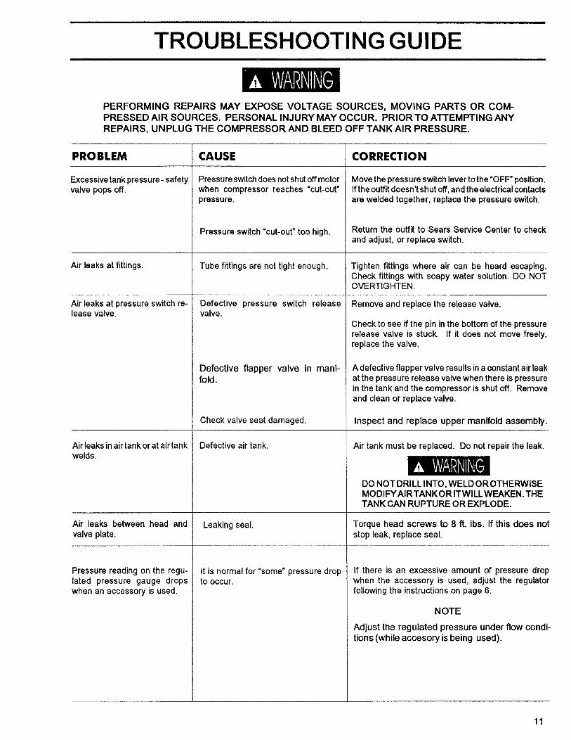
TROUBLESHOOTING GUIDE
PERFORMING REPAIRS MAY EXPOSE VOLTAGE SOURCES, MOVING PARTS OR COM-PRESSED AIR SOURCES. PERSONAL INJURY MAY OCCUR. PRIOR TO ATTEMPTING ANYREPAIRS, UNPLUG THE COMPRESSOR AND BLEED OFF TANK AIR PRESSURE.
PROBLEM
Excessive tank pressure- safetyvalve pops off.
Air leaks at fittings.
Air leaks at pressure switch re-lease valve.
Air leaks in air tank orat air tankwelds.
CAUSE
Pressure switch does not shut off motor
when compressor reaches "cut-out"pressure.
Pressure switch "cut-out" too high.
Tube fittings are not tight enough.
Defective pressure switch releasevalve.
Defective flapper valve in mani-fold.
Check valve seat damaged.
Defective air tank,
CORRECTION
Move the pressure switch lever to the "OFF" position.If the outfit doesn't shut off, and the electrical contacts
are welded together, replace the pressure switch.
Return the outfit to Sears Service Center to checkand adjust, or replace switch.
Tighten fittings where air can be heard escaping.Check fittings with soapy water solution. DO NOTOVERTIGHTEN.
Remove and replace the release valve.
Check to see if the pin in the bottom of the pressurerelease valve is stuck. If it does not move freely,replace the valve,
A defective flapper valve results ina constant air leakat the pressure release valve when there is pressurein the tank and the compressor is shut off. Removeand clean or replace valve.
Inspect and replace upper manifold assembly.
Air tank must be replaced. Do not repair the leak.
DO NOT DRILL INTO, WELD OR OTHERWISEMODIFYAIRTANKOR ITWlLLWEAKEN.THETANK CAN RUPTURE OR EXPLODE.
Air leaks between head and Leaking seal. Torque head screws to 8 ft. Ibs. If this does notvalve plate, stop leak, replace seal.
tt is normal for "some" pressure dropto occur.
Pressure reading on the regu-lated pressure gauge dropswhen an accessory is used.
If there is an excessive amount of pressure dropwhen the accessory is used, adjust the regulatorfollowing the instructions on page 6.
NOTE
Adjust the regulated pressure under flow condi-tions (while accesory is being used).
11
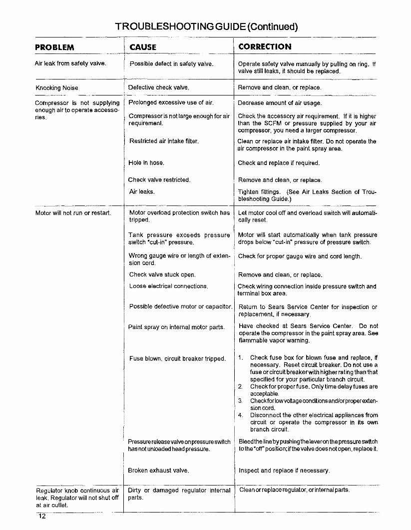
TROUBLESHOOTING GUIDE (Continued)
CAUSE
Possible defect in safety valve.
PROBLEM
Air leak from safety valve.
Knocking Noise
Compressor is not supplyingenough air to operate accesso-ries.
Motor will not run or restart.
Defective check valve.
Prolonged excessive use of air.
Compressor is not large enough for airrequirement.
Restricted air intake filter.
Hole in hose.
Check valve restricted.
Air leaks.
Motor overload protection switch hastripped.
Tank pressure exceeds pressureswitch "cut-in" pressure.
Wrong gauge wire or length of exten-sion cord.
Check valve stuck open.
Loose electrical connections.
Possible defective motor or capacitor.
Paint spray on internal motor parts.
Fuse blown, circuit breaker tripped.
Pressure releasevalve onpressure switchhas not unloaded head pressure.
CORRECTION
Operate safety valve manually by pulling on ring. Ifvalve still leaks, it should be replaced.
Remove and clean, or replace.
Decrease amount of air usage.
Check the accessory air requirement. If it is higherthan the SCFM or pressure supplied by your aircompressor, you need a larger compressor.
Clean or replace air intake filter. Do not operate theair compressor in the paint spray area.
Check and replace if required.
Remove and clean, or replace.
Tighten fittings. (See Air Leaks Section of Trou-bleshooting Guide.)
Let motor cool off and overload switch will automati-
cally reset.
Motor will start automatically when tank pressuredrops below "cut-in" pressure of pressure switch.
Check for proper gauge wire and cord length.
Remove and clean, or replace.
Check wiring connection inside pressure switch andterminal box area.
Return to Sears Service Center for inspection orreplacement, if necessary.
Have checked at Sears Service Center. Do notoperate the compressor in the paint spray area. Seeflammable vapor warning.
1. Check fuse box for blown fuse and replace, ifnecessary. Reset circuit breaker. Do not use afuse or circuit breaker with higher rating than thatspecified for your particular branch circuit.
2. Check for proper fuse. Only time delay fuses areacceptable.
3. Check for Iowvoltage conditions and/or proper exten-sion cord.
4. Disconnect the other electrical appliances fromcircuit or operate the compressor in its ownbranch circuit.
BleedtheUneby pushingthe leveronthe pressureswitchtothe"off" position;if the valvedoesnotopen, replace it.
Broken exhaust valve. Inspect and replace if necessary.
Regulator knob continuous air Dirty or damaged regulator internal Cleanorreplaceregulator, orinternalparts.leak. Regulator will not shut off parts.at air cutlet.
12

SERVICE NOTES
13
i
SERVICE NOTES
14

SERVICE NOTES
15
SEARSCRA_SMAN
SERVICE
MODEL NO.
HOWTO ORDERREPAIR PARTS
GENERAL MANUAL FOR
PERMANENTLY LUBRICATEDTANK MOUNTED
AIR COMPRESSOR
Now that you have purchased your Sears Air Compressor, should aneed ever exist for repair parts or service, simply contact any SearsService Center and most Sears stores. Be sure to provide all pertinentfacts when you call or visit.
The model number of your Sears Air Compressor can be found on thetop of the motor cover or on the tank.
WHEN ORDERING REPAIR PARTS, ALWAYS GIVE THE FOL-LOWING INFORMATION:
• PART NUMBER • PART DESCRIPTION
• MODEL NUMBER • NAME OF ITEM
All parts listed may be ordered from any Sears Service Center andmost Sears stores.
If the parts you need are not stocked locally, your order will beelectronically transmitted to a Sears Repair Parts Distribution Centerfor handling.
Sears, Roebuck and Co., Chicago, IL 60684 U.S.A.