people.cs.nctu.edu.twsjyang/thesis/all post pages.docx · web viewchapter 1 introduction. in the...
TRANSCRIPT
Chapter 1 Introduction
In the rapid changing semiconductor industry, volume production of compulsory
memory integrated circuits such as DRAM and FLASH has yet reached a critical point of
supply over demand. However, these memory solution companies cannot just stop making
products to reduce the supply because these factories, usually called FABs, need to produce
some goods to balance the tool depreciations to the company. Some enterprises come up with
a solution of manufacturing foundry goods such as CMOS image sensors or other profit
worth foundry products to keep the factory running. This change of manufacturing in the
FAB results in various combinations of products to be manufactured in the same FAB, and
thus change would not only affect the cycle time (CT) of the original massive single products
but also the cycle time of the new products.
In the process of semiconductor manufacturing, a sequence of operations such as
photolithography, etching, diffusion, and thin film deposition is run over and over to make an
integrated circuit (IC) on a silicon wafer. This may sum up to hundreds of operations in
combinations with sample testing operations to complete. These wafers are carried in a
container known as front opening unified pod (FOUP) in a 300 mm FAB. Among these
operations, not only one FOUP is used throughout the entire production; these FOUPs need to
be exchanged due to materials or particles contaminated throughout the process or, to be
exchanged to FOUPs that fit to new hardware docks. Although these FOUP exchange
operations may not occupy much of the entire production but they are essential to the
production process and most important of all, they will occupy traffic in the FAB and affect
the cycle time of all the products to be delivered on-time, especially when the amount of
these FOUPs are short or one of these FOUP exchange equipments failed to function
1

properly.
In this chapter, we will describe the problems we have encountered first, then the aim of
this thesis. After that, we will introduce the method to be used and the thesis layout at end of
this chapter.
1-1 Problems Encountered
As we have mentioned above, the FOUP exchange operation consumes time for a
product to complete as well as it may cause traffic in the FAB due to FOUP transportations.
In addition, these empty FOUPs are kept in FOUP exchange tools called sorters [1] and are
distributed in certain places in the FAB. This indicates that all these product-contained
FOUPs and empty FOUPs would have to be delivered to this location of the FAB that could
possibly and potentially provide another bottleneck of traffic in the FAB if the routes of
overhead hoist transports (OHT) to the sorters are blocked. To conclude these problems, we
may summarize three main issues: 1. Time wasted for empty FOUP and FOUP with products
to be delivered to FOUP exchange tools, 2; the traffic caused by these operations and 3; the
distribution of empty FOUPs would not be uniformed or balanced in the FAB.
1-2 Aim
With the new version of SEMI standard SEMI E94.1-1107[2], FOUPs containing
products to be processed are delivered to the tools and then unloaded from the equipments’
load ports after the control process has started. By using the concept of “Manufacturing
Optimization Improvements Leveraging SEMI E94-1107”[3] and “Enabling Material
Redirection in the Next-Generation Factory”[4], the aim of this thesis is to introduce a solution
of reducing cycle time and improve the throughput of a product by redirecting the FOUP after
all the wafers needed to be processed had successfully loaded to its’ process equipments and
2

deliver the required empty FOUP to carry the finished lots after processing, i.e., to reduce the
time taken for these FOUP exchange operations in order to save products’ cycle time as well
as ease up the traffic in the FAB. This would eliminate the FOUP exchange operations and
could solve the three problems mentioned above at a time after the methodology of this thesis
is introduced. The potential risk of this mechanism would be the additional computing
consumptions required for the calculations redirecting the FOUPs but as to the result, which
will be discussed in chapter 3, the additional logic added would not make the computers to
suffer.
1-3 Methods
As far as mentioned, the aim of the thesis is to reduce the cycle time for manufacturing a
semiconductor product. Before the experiment started, some data such as average cycle time
of products, the average FOUP exchange rate and related transfer time from a memory
production FAB was collected. These data were then transferred to a simulation
environment. After that, some modification of the manufacturing execution system (MES)
program was made on the testing environment to simulate the action of dispatching away the
FOUP of loaded lot and deliver the desired FOUP following the concept of SEMI E94-1107.
The modification of the program was not applied to all the equipments in the FAB because.
Not all the operations in the manufacturing process would need the new function due to
actual equipment constraints as well as the operation itself, i.e., the next manufacturing
operation may not need to have the FOUP exchanged. The program contained logic to judge
the operations that are required for this unloading FOUP process together with the empty
FOUP selection logic to optimize the entire dispatching process.
1-4 Thesis Layouts
3

Chapter 2 describes how the computer integrated manufacturing (CIM) FAB operates by
introducing the MES and how it is associated with other systems such as tool control systems
(TCS) and Automated Material Handling Systems (AHMS) to control the full automated
FAB. Chapter 3 shows the parts of the objects in chapter 2 are modified to establish the
scenario of this thesis and display the experiment result. Data analysis and comparison is in
Chapter 4. Some benefits and further implementation discussion are in the conclusion
chapter, Chapter 5.
Chapter 2 Background of Automation in Semiconductor
Manufacturing
4

As we have mentioned in Chapter 1, there are some problems regarding to the cycle
time of semiconductor manufacturing that we may work on to improve. Before we head to
the experiment thoroughly, let us take a glimpse on the evolution of automation in
semiconductor manufacturing when it comes to a new era of 300 mm FABs. We will discuss
the systems used for an automated 300 mm FAB in section 2-1, followed by the processes
regarding to FOUP exchanges and its purpose in 2-2. Section 2-3 describes how the method
in this thesis is applied with the systems mentioned.
2-1 Automation in Semiconductor Manufacturing
We know that semiconductor manufacturing is a combination of four main processes
that runs over and over depending on the product complexity. These processes are
photolithography, etching, thin film decomposition, and diffusion. In addition to these
repeated processes, we usually apply some quality check operations in between to ensure that
the process we just applied on the wafer is made to standard. For example, some alignment
checks are required for photography process so that all the lines or circuits to be produced
later shall all lie in their perfect positions. The repeated steps are run over and over with
different recipes and various data are collected to form a single chip. However, since we
cannot remember all the operations to be handled and all the values to be tuned and applied
throughout the process, the manufacturing execution system (MES) is introduced.
This system acts as a manager that keeps all the definitions or specifications required for
a product to be run in its database. The MES can judge what operations for a lot to be run
next as well as what recipes defined to be executed. These packages of data are transferred to
the equipments through tool control system (TCS). The TCS will arrange a sequence of jobs
called control jobs for the equipment automation program (EAP) to provide equipments
detailed data. The EAPs have codes standardized by SEMI or commands defined by the
5
equipment manufacturer to communicate with the equipment, e.g., commands to load or
unload the FOUP.
The final systems that chained up the entire automation of a FAB to make a full
automated FAB possible are the material control system (MCS) and the automated material
handling system (AMHS). With the communication of MES and MCS, MES requests
transfer commands to MCS and MCS then calculates the best route for a FOUP to be carried
from one place to another. These transfer commands created will then be executed by AMHS
for the overhead hoist transports (OHT) or other transportation devices to deliver the goods.
While transferring, the MCS reports the transfer status such as the location of the FOUPs to
MES so that the products could easily be found in the entire FAB.
With the assistance of the four systems, a 300 mm semiconductor FAB can be operated
automatically1 as block diagram shown in Fig. 2.1. Elaborated from Fig. 2.1, Fig 2.2 shows
what it may look like in the FAB with the control of the four systems.
1. The automation mentioned here is the basic abstract of automation. More judgments are required depending on the needs of a FAB. These other decisions are assisted by real time dispatcher (RTD) systems[5], advance process control (APC) systems, and statistical process control (SPC) systems. These systems are hooked up to the CIM framework by connections with MES.
6

Fig. 2.1 Block diagram of 300mm FAB automation systems.
7
TCS MES MCS
AMHS
OHT
EAPs
MES DB(Product Spec.
Definition) OHT
OHT
OHT
Equipments

Fig. 2.2 Controls of the four systems inside the FAB.
2-2 Operations in semiconductor manufacturing
We have now acknowledged the concept of automation in a semiconductor FAB. We
will now discus the operations in detail on why the FOUP exchange operations are needed in
a manufacturing process as well as the types of FOUP exchange operation in an automated
FAB. Before we start, let us acquire the knowledge of the types of the equipments in the
FAB.
There are two main types of equipments in the FAB, one is fixed buffered equipment
8
PC
MES User Interface
OHTs
Equipment Load Ports Oper
ator
Track
Track to EQP
Equipment
controlled by TCS EAP
Controlled
by MCS AMHS

and the other is internal buffered equipment. The fixed buffered equipments do not have
internal shelves to have the lots loaded inside the equipment as diagramed in Fig. 2.3.
Fig. 2.3 Concept of a fixed-buffered equipment.
Although the term “fixed buffered” is used, there are actually no extra spaces for the
wafers to be stored temporarily, and both the FOUPs and wafers are kept in one place on the
load port of the equipment as a buffer. The loaded FOUP do not have further transpor-
tations into these equipments, therefore we call these equipments a fixed buffered type.
These types of equipments consist of processing equipments and quality check equipments.
Sorters are also classified as fixed buffered equipments. These equipments usually process
wafers in a sequential manner.
9
Chambers
Unselected wafers in
FOUP Load Ports acts as fixed buffer
Wafer in
process
Robotic arms move wafer

Please note from Fig. 2.3, we can see that once the FOUP is loaded (or docked) to the
equipment, it stays on the load port and the robotic arms will move the wafers to their
respective chambers to process depending on the process recipe defined while the wafers
waiting for process stays in the FOUP. When the wafers are done, they are transferred back
to the FOUP on the load port of the equipment and the next wafer is loaded to the chamber.
Fig. 2.4 depicts a conceptual flow diagram of what happens when the reserved lot is
loaded to the equipment and being processed. When the FOUP is being loaded onto the
equipment, the TCS sends a process transaction to MES to check if the loading FOUP is able
for process for the equipments. These checks include information defined in MES as well as
the recipes logically defined2 in TCS. The wafers are then processed one after the other
after the control job is sent from TCS to the EAP. All the communication codes and data
from the equipments are parsed in the EAP before sending back to MES from TCS. There
are some more detailed interactions and communications for wafer processing which will not
be discussed in this thesis.
2. We use the term logically defined here for recipes is because the actual recipe that should be executed is predefined in the equipment configuration itself, called physical recipe. MES cannot control the physical recipe configurations in detail such as which chambers of the equipment should be run for the product.
10
11
LOT loaded to equipment
Check process recipes
TCS sends process tasks to EAP
Process wafers one by one
TCS packs the reports and sends operation complete
data to MES
EAP catches process data report and sends to TCS

Fig. 2.4 Conceptual flow diagram of processing a lot for fixed-buffered equipment.
As to internal buffered equipments, the FOUPs are loaded from exterior load ports and
are moved to shelves embedded inside the equipment. This is mainly because within internal
buffered equipments, the lots can be processed in forms of batches. In other words, all wafers
of lots are firstly removed from FOUPs on the shelf to a furnace tube or tank to be processed
at a time so that more than one lot can be run within one operation to maximize the
throughput of the equipment as shown in Fig 2.5.
Fig. 2.5 Concept of internal buffered equipment, furnace example.
Fig. 2.5 demonstrates an example of furnace equipment. We can see that there are eight
shelves drawn in the diagram and once the wafers are charged onto the tube, the tube will
then be raised into the furnace for process. With this type of equipment, the load ports are
usually emptied since the FOUPs are on the shelves inside the equipment. The empty FOUPs
12
……
Load Port 2
Load Port 1
FOUPs must be loaded to
internal shelves first
Entire tube loaded into
furnace
Furnace
Shelves
Furnace Tube loader
FOUPs loaded in shelves acts as buffers

will wait for the entire process to be finished and then discharged from the tube back to their
original FOUPs. For where the wafers to be returned to, the FOUPs are pre-defined in the
control job while operation starts for the process.
The main difference between fixed buffered equipment and internal buffered equipment
is that all the wafers are pulled out from the FOUP in the internal buffered equipment
whereas the wafers stays in the FOUP until it is their term to be processed in the fixed
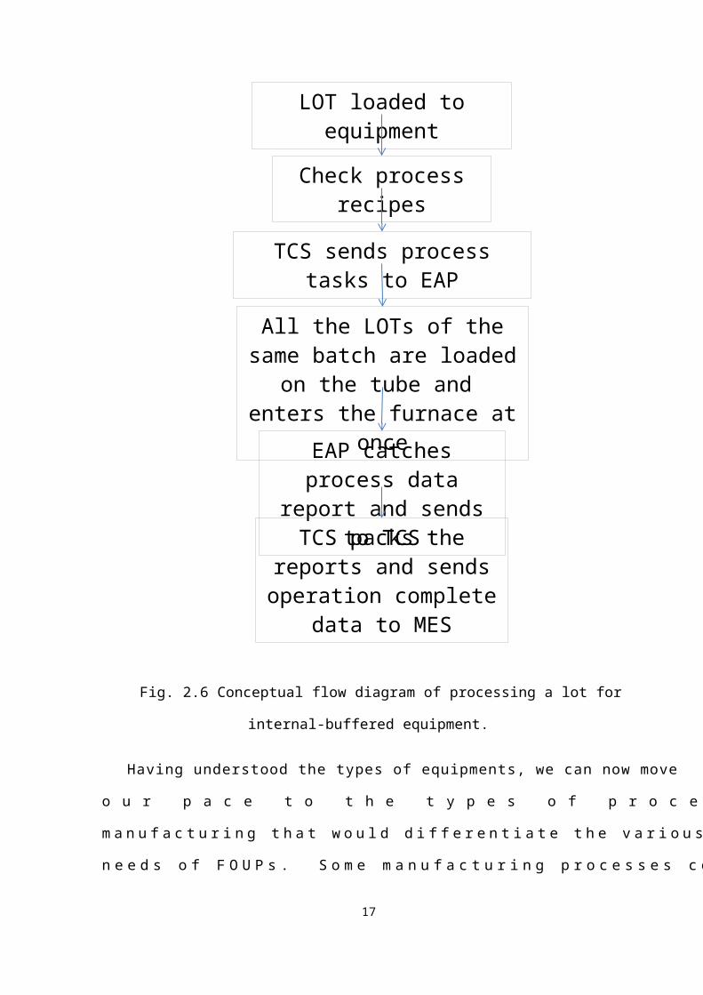
buffered equipments. In addition, from the flow diagram of Fig. 2.6, we can compare with
Fig. 2.4, the procedures of the internal-buffered equipment is different than that of fixed-
buffered equipment.
13

14
LOT loaded to equipment
Check process recipes
TCS sends process tasks to EAP
All the LOTs of the same batch are loaded on the tube and enters the furnace at once
TCS packs the reports and sends operation complete
data to MES
EAP catches process data report and sends to TCS
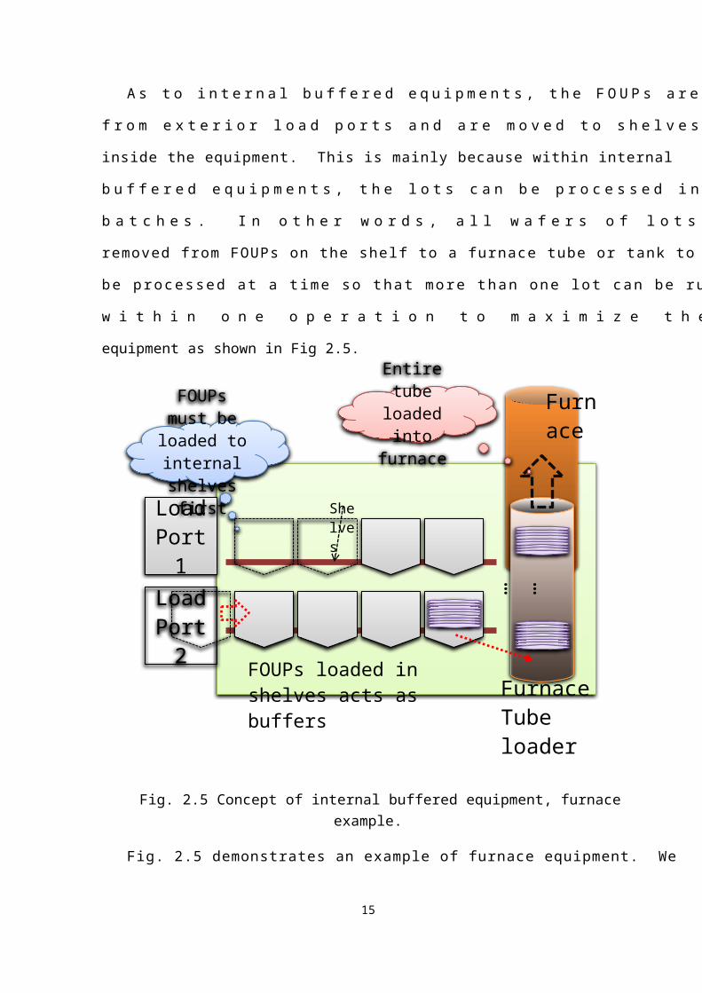
Fig. 2.6 Conceptual flow diagram of processing a lot for internal-buffered equipment.
Having understood the types of equipments, we can now move our pace to the types of
processes in semiconductor manufacturing that would differentiate the various types of needs
of FOUPs. Some manufacturing processes contain high quantity of metallic vapor or
particles that will be contaminated along the wafers as well as its carriers, FOUPs. After
these kinds of operations, the wafers must be transferred to FOUPs categorized as “After-
Metal” FOUPs. And before those operations, the wafers are carried in “Before-Metal”
FOUPs. When the lots are being cleaned, they have to be moved back to “Before-Metal”
type FOUPs again for yield control. The number of changes of these FOUP exchanging
operations may differ according to different types of products. In a fully automated FAB,
these operations are done by sorter equipments where empty clean FOUPs are located in
sorter shelves as well as the lots required for FOUP exchange. Since sorters are not key
equipments and may occupy a big portion of space in the FAB, the automated sorters do not
come up with numbers. However, the contaminated products cannot be dispatched to their
next operations if the FOUPs have not been changed to the desired ones. These lots may sit
in stockers for periods of time from minutes to hours depending on the dispatching system.
More detailed numbers of the collected data will be discussed in Chapter 4 for these FOUP
exchange operations.
Furthermore, discussions of FOUP exchange operations may include some equipments’
load ports are not capable of new type of FOUPs, i.e., the docking of the equipment cannot
comply with some new types of FOUPs. The lots in these FOUPs may have to wait to be
exchanged as well and this may consume cycle time. Finally, some products with high yield
concern may have to be processed in dedicated FOUPs and these lots will also require FOUP
exchange operations. In the next section, we will discuss how the new metho- dology is
15

applied in this thesis to shorten the cycle time by “In-Process-FOUP-Exchange” (IPFE)
function.
2-3 Implementations on In-Process-FOUP-Exchange
Before we start on discussing the implementations of the In-Process-FOUP- Exchange
(IPFE) function, we have to narrow down the jobs to be done by looking through what tasks
or procedures there are from MES to equipments. We will go through the automation system
hierarchy as shown in Fig. 2.7 from bottom up. As we have mentioned in Fig. 2.4 and Fig.
2.6 the sequence of manufacturing in section 2-2, the equipments are controlled by EAP
through TCS in FAB automation. The EAP performs only the Control Job (CJ) [6]
Fig. 2.7 The MES – Equipment hierarchy.
When the equipment’s load port is empty and ready to process lots, it will signal a load
16
Equipment
EAP
TCS
MES
request from EAP to TCS and then to MES, the MES will return some lots available for
processing. In FOUP exchange operations, MES will then return the lots as well as empty
FOUP for this operation. Once TCS obtained the lots from MES, it will reserve the FOUP for
transport and signal this event to AMHS through MES. After the FOUP has been transported
and loaded to the equipment, TCS will handle a sequence of operations as Fig. 2.4 or Fig. 2.6
depending on the type of the equipment (fixed buffered or internal buffered). TCS checks
again with MES the lot loaded to be sure whether if this lot can be processed by the
equipment and is ready to prepare the Control Job (CJ), which is the actual job the equipment
will execute to process the lot, for the EAP to be sent to the equipment. The EAP performs
only the Control Job assigned by TCS and most of the information such as attributes or
recipes for the equipment to be processed to the lot is defined in the Control Job. After the
equipments are done with the lots, the CJ end signal is sent to TCS and TCS will ask MES for
where the finished lots to be transferred and the cycle repeats from an empty load port. There
are much more jobs to be done by TCS in the lot processing sequence but will not be
mentioned in this thesis. However, the sequence of jobs would of course follow the
specification defined by SEMI standard with minor changes depending on the need of each
FAB. Any exceptions in between the sequence of jobs would terminate the job to proceed
and the equipment will send alarm signal on site as well as to TCS.
Fig. 2.8 is the actual sequence flow diagram of the jobs and events between TCS and the
17

equipment while processing a product. We use labels T1 to T5 to illustrate signals send by
TCS and E1 to E15 to represent the signals send from the equipment. The EAP, in this
circumstance, acts as an interface between TCS and the equipment, i.e. the EAP handles the
signals from both sides and translates what to be done or what to be reported for TCS and the
equipment. This diagram is important because the diagram will help us to explain the
changes we made to make the In-Process FOUP Exchange function to work, which will be
described in Chapter 3.
18

19
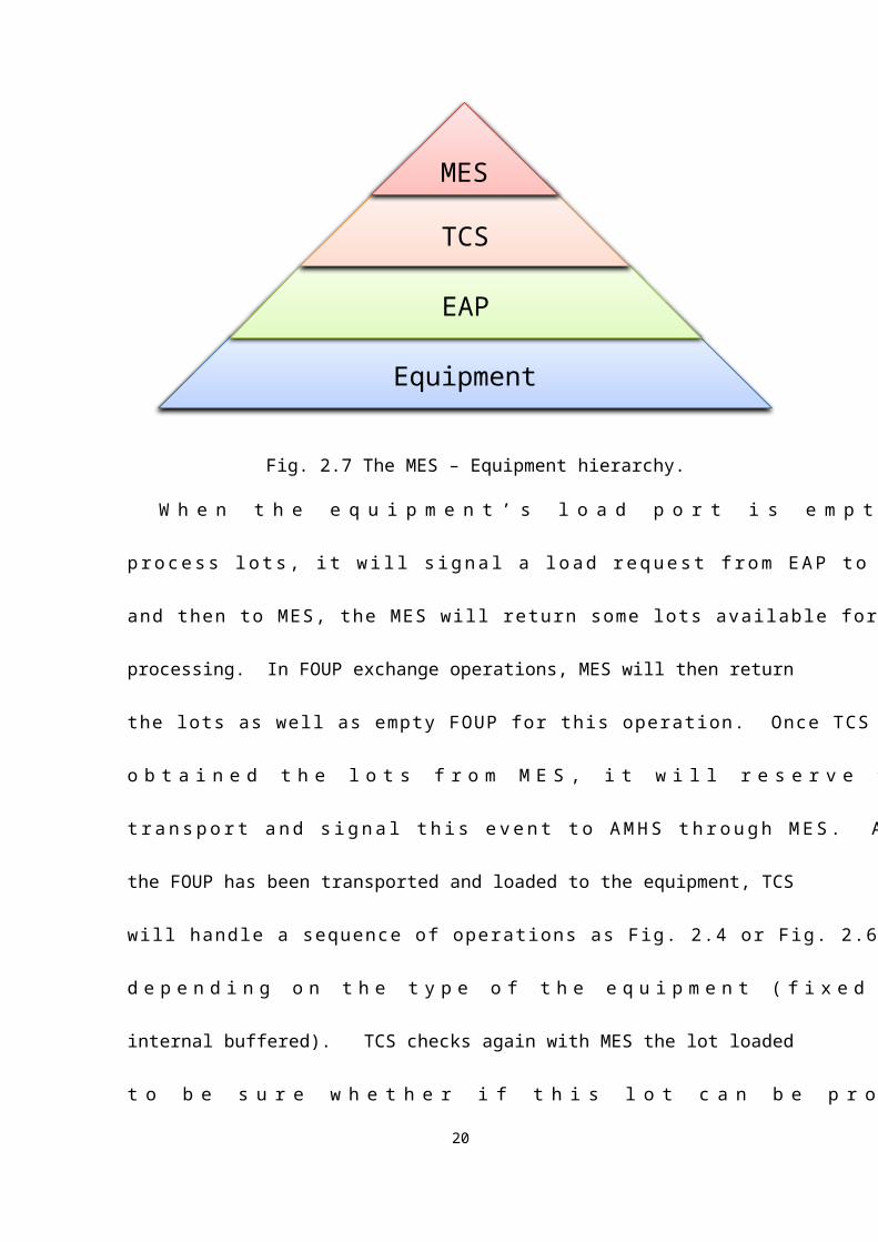
Fig. 2.8 Sequence flow diagram of events to be handled by EAP for TCS and the
equipment.
To make Fig. 2.8 a more readable example, we use the example of a sorter to demons-
trate a cycle of an equipment operation. This is shown from Fig. 2.9(a) to Fig. 2.9(e).
20
Load Port 1
Load Port 2
Sorter X1 EAP: Load ports and equipment empty.TCS: Load Request, ask MES for WIPMES: Found LOT and empty FOUPTCS: Reserve result of MES and signal transfer request to MESMES: Request MCS for transfer jobMCS: Send command to AMHS for transfer job

Fig. 2.9(a) Sorter example – when equipment is empty and ready for operation.
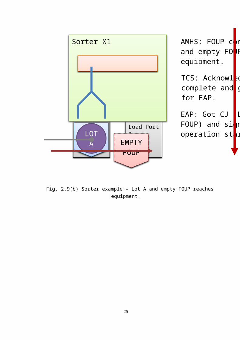
Fig. 2.9(b) Sorter example – Lot A and empty FOUP reaches equipment.
21
Load Port 1
Load Port 2
Sorter X1 AMHS: FOUP containing LOT A and empty FOUP delivered to equipment.TCS: Acknowledges load complete and generating CJ for EAP.EAP: Got CJ (LOT A Empty FOUP) and signal equipment operation start.
LOT A
EMPTY
FOUP

Fig. 2.9(c) Sorter example – Wafers are being transferred to new empty FOUP.
22
Load Port 1
Load Port 2
Sorter X1Equipment: Wafers are moved by robotic arms from original FOUP to new empty FOUP.EAP: Send report data to TCS if any.
TCS: Signal MES Operation Complete after all the processes are done.
LOT A
LOT A
Load Port 1
Load Port 2
Sorter X1 MES: Make LOT information to new FOUP and shift LOT operation to next operation.TCS: Unload Request, ask MES where to deliver finished FOUPs.MES: Checks destination and returns resultTCS: Request for FOUP transfer
Old empti
ed FOUP
LOT A
MES: Request MCS for transfer jobMCS: Send command to AMHS for transfer job

Fig. 2.9(d) Sorter example – Operation completed and ready to be carried away.
Fig. 2.9(e) Sorter example – FOUPs being carried away from equipment.
We have now the concept of how the lots are being processed in an automated FAB.
The next thing we would discuss is how we could use the concept of SEMI standard
document E94.1-1107 to accomplish our needs. In FOUP exchange operations, the original
23
Load Port 2
Load Port 1
Sorter X1AMHS: Transfer the completed FOUP away from equipment.TCS: Report to MES latest equipment status (Unload Complete).
LOT A

Control Job assigned by TCS would require a source FOUP and a destination FOUP after
MES returned what to be processed on a sorter. For the IPFE operation, the lots are
processed in either fixed or internal buffered equipments. However, most of the fixed
buffered equipments do not process the entire lot at a time whereas taking the wafers one by
one into the equipment chambers sequentially (Fig. 2.3). In addition, as we look into the
operations of an IC fabrication, the FOUP exchange operations are mostly performed after
internal buffered equipments due to before metal or after metal gas contamination concerns as
we have mentioned earlier. Therefore, we will only discuss the IPFE function operation cases
on lots that has to be processed in the internal buffered equipments in this circumstance.
According the SEMI standard E94.1-1107, the attribute named “MtrlOutSpec” has two
main data fields, the “SourceMap” (source FOUP) and the “DestinationMap” (destination
FOUP). These fields are not filled in either fixed or internal buffered operations since the
source and the destination is the same and the lots will return to the original FOUP after
process completion. In the IPFE operation, we will make use of this attribute by inserting the
“SourceMap” when control job starts while leave “DestinationMap” the same as
“SourceMap” at the beginning3 . After we have successfully loaded the lots into the
equipment for processing, the EAP would sense the event of wafers in the tube being loaded
3 According to the SEMI E94-0309 specification, once the MtrlOutSpec attribute is set to Material Redirection Mode, the destination attribute could be set by the SetAttr option described in SEMI E39.1-1103[7] document. We can assign a new destination FOUP ID for the required process.
24
or pushed into the furnace and notify TCS as in Fig. 2.5. This notification would trigger TCS
to send a new inquiry transaction for MES to ask for an empty available FOUP that would
suit the processing lot for the next operation according to the flow definition defined in
advance. In this new inquiry transaction, MES calculates and determines which empty FOUP
to be assigned. The dispatching logic of the empty FOUP in MES will be discussed in detail
in Chapter 4, the discussion chapter. Once the empty FOUP is decided and sent to the
equipment, TCS would ask EAP to unload the original FOUP that carried the lot from the
load port of the equipment. As soon as the old empty FOUP has been unloaded from the
equipment load port, EAP will capture this signal ask transportation of the new empty FOUP
to the equipment. The detailed description of the procedure will be described in chapter 3.
TCS, at this moment, would ask MES where to deliver the original empty FOUP; either this
FOUP could be used again and sent back to a nearby stocker or, to some other locations such
as FOUP cleaning locations. This is similar to end of process in figure 2.8(d) where the
FOUPs are to be carried away. Then, TCS will use the attribute “SetAttr” defined in SEMI
E39-0703[7] and SEMI E39.1-0703[8] to update the CJ attribute “DestinationMap” previously
mentioned to provide the new empty FOUP information while arrival of the new FOUP.
After the lot has finished the processing, EAP would return the lot into the updated
“DestinationMap” FOUP. TCS, by acknowledging unload request by the EAP, would check
with MES again where to deliver this finished lot and the IPFE operation is complete with the
25

original operation complete function.
We have now finished the basic concept of a 300 mm FAB automation framework and
the new IPFE operation. By using this new IPFE operation, we would expect the average
cycle time of a product to be reduced by the average waiting time plus the original FOUP
exchange time as my hypothesis. This cycle time reduction will not only benefit the product
applied but also the other products due to the relaxation of the sorter throughput. In the next
chapter, we will make the previously mentioned procedures into practice in a simulated
environment as well as presenting the results.
26

Chapter 3 The Experiment
In this chapter, we will discuss the experiment. We have described the concept of TCS,
EAP, and equipment sequence process in Fig 2.8. Fig 3.1 shows the flow of the two main
operations of a semiconductor production flow by which the circles represents the operation.
27
Internal
Buffered
Operation I1
FOUP Exchan
ge Operati
onX1
Layers of operations
W1
2 of 800 Operations in a product flow.
W2

Fig. 3.1 Part of the operations in a product flow.
The first circle in Fig. 3.1 on the left hand side is an internal buffered operation, labeled
I1. In this operation, all the lots to be processed are run in a batch, or group. The batched
lots are removed from their FOUPs and the FOUPs are kept in the shelves inside the
equipment as in Fig. 2.5 and the wafers are loaded into a furnace. In the original process
flow, the wafers are moved back to their original FOUPs from the furnace tube after step E13
of Fig. 2.8. These FOUPs are then unloaded from the equipment to the stocker and wait for
the next operation. We assign a smaller circle labeled W in Fig. 3.1 to represent the “idle” or
“waiting” status of these lots. The next operation on the right hand side indicates a FOUP
exchange operation, labeled X1. In this operation, the wafers are required to be transferred
from a certain type of FOUP, say Before Metal FOUP, to an After Metal FOUP due to metal
contamination constraints. We simply call the types of the FOUPs B-type and A-type
respectively. After the X1 operation, the B-type FOUP is emptied, it is then transferred to a
FOUP cleaning equipment for further use; the A-type FOUP will then contain the wafers of
the lot.
In section 3-1, we will describe what modifications of software we have done to make it
work using the SEMI E94-1107 standard as well as the problems that may encounter. In
section 3-2, we will discuss the solutions to 3-1 and their trade-offs. Finally, the results of the
experiment in section 3-3.
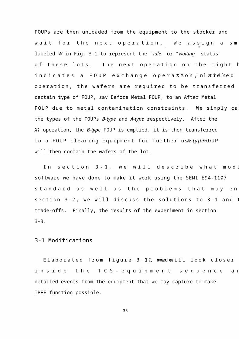
3-1 Modifications
Elaborated from figure 3.1, node I1, we will look closer inside the TCS-equipment
sequence and discuss some more detailed events from the equipment that we may capture to
make IPFE function possible.
28

In current TCS control job creation, the content of attribute “MtrlOutSpec” is left blank
and the EAP software takes the content “SourceMap” and “DestinationMap” as the same
value. These two contents provide the FOUP ID to let the equipment know where to take the
wafers from and where to place the finished wafers back after process. The first modification
takes place while TCS creates the control job. We provided the whole content of the
“MtrlOutSpec” according to the SEMI specification with both “SourceMap” and
“DestinationMap” the same data since we have not decided the new empty FOUP yet. This
modification is in step T4 of Fig. 2.8. After all the wafers of the same batch lots are loaded
into the furnace tube and the process started as step E10 of Fig. 2.8, EAP will catch this event
and signal TCS. This event gives us a new T6 transaction from EAP to TCS as shown in Fig.
3.2. We label the transaction such as M1 in the figure to indicate the transaction being sent
from MES.
29

Fig. 3.2 Additional modifications in EAP event handling elaborated form Fig. 2.8.
Continue with Fig. 3.2, TCS will send a new transaction, T7, to MES to inquire a new
empty FOUP when the furnace is loaded if the process time of the batch has more than an
hour left. The inquiry input would be some basic information of the first lot in the batch such
as type of FOUP required, lot’s product name, lot’s flow name, and lot’s operation number…
etc. The one-hour-buffer is to be kept for any exceptions that would require human resources
to take over. For example, we may expect some transportation issue due to hardware failure
and this buffer could be used for operators or engineers to recover the chance of the finished
wafers having no FOUP to return after process since the original FOUP may not be on site.
This problem will be discussed in section 3-2. MES, on the left side of Fig. 3.2, would
calculate whether to return a new empty FOUP or the ID of the original FOUP and return the
result in M1 as well as mark an transfer reserve record on the new FOUP in case of this new
FOUP being selected by other operations in the FAB. TCS then examines if the returned
FOUP ID is the same as what had provided in the inquiry transaction. If the FOUP ID
remains the same, TCS will use the next lot in the batch for next inquiry. Otherwise, TCS
will use “SetAttr” to modify the control job’s “DestinationMap” content, T8. By receiving an
update success, TCS will tell EAP to unload the old FOUP, T9, inside the equipment and ask
MCS to make a transfer command, T9’, to carry this old FOUP away by means of MES; if
“SetAttr” had failed, the “DestinationMap” would remain the same and TCS cancels the
transfer reservation made in M1 earlier and move to next lot in batch. When the old FOUP
leaves the load port of the equipment, T10, EAP could sense this signal and notify TCS such
that TCS can then ask MES to establish another transfer command to MCS for the new FOUP
to be transferred, T10’. The reason of the asynchronous transfer rather than transferring both
the old and the new FOUP at the same time will be discussed later in this thesis. When the
new FOUP has successfully arrived and docked to the equipment load port and moved to
30

shelf inside the equipment, the new FOUP is ready to be filled with finished wafers. The
same cycle will be repeated for the same batch of products until no changes are required.
This is the first portion of IPFE.
The second portion of IPFE is when the wafers have finished process. After the
products have finished their process in the furnace, the wafers are transferred to the new
FOUP while reporting an operation complete to MES. A new operation complete transaction
is introduced here because in this transaction, we need to call a FOUP exchange operation as
well as a skip operation since the original operation X1 is no longer needed and the
information of the lot should be at W2 of Fig. 3.1 instead of W1. In other words, the next
operation of the LOT will be the one after the original FOUP exchange operation, status
“waiting” at W2 of Fig. 3.1.
As we can see from Fig. 3.3, we have bisected the times needed for the original flow
process.
31
Internal Buffered Operati
on I1
FOUP Exchang
e Operati
onX1
W1
W2
TF
Ti
Tm
TX
S ETSE

Fig. 3.3 Time required for operation in original scheme.
In Fig. 3.3, the total time used in the original scheme from point S to point E would be
TF (time for furnace operation) plus Ti (time wait for sorter operation, idle time) plus TX (time
for sorter operation to complete). Tm in the figure is calculated in Ti because the average time
required for Ti is calculated from the events of end of TF to the start of TX. TSE , therefore, is
the total time required in the original product scheme, which will be denoted as function:
TSE = TF + Ti + TX (Eq1)
On the other hand, Fig. 3.4 gives us what we did for the IPFE function. The shaded part
W1 and X1 with the respective times required Ti and TX is eliminated and a new arc is drawn
from the end point of operation I1 to the start point of W2.
Fig. 3.4 IPFE function acts as an arc over W1 and X1 operations.
We can tell from Fig. 3.4, since we have done all the work for X1 while the lots are in
32

the process of I1. When the lot is completed with process I1, the lot status would be
“waiting” at beginning of W2. Therefore, by using the IPFE function, the new total time
elapsed for I1 to end of X1 would be calculated as from point S to point E’ in Fig. 3.4. This
gives us a new time line, TSE’, in Fig. 3.4. This new time line is equal to that of the lot being
processed in operation I1 and would be:
TSE’ = TF (Eq2)
or
Tdiff = TSE - TSE’ (Eq3)
And as to the ratio of time reduction R using IPFE function, compared with the original
scheme, we may obtain:
R% = (Tdiff) / (TSE) (Eq4)
The value of Tdiff may be different in the above formula since Ti may vary in the original
scheme, which depends on the work in process (WIP) of the sorters. We will discuss more
about the benefit obtained from IPFE function with statics in chapter 4.
Before we end this section, there is a main problem that we might encounter using the
IPFE function. That is, while the old FOUP has been removed or unclamped from the
equipment, we cannot definitely be sure if the new FOUP could be delivered. This may be
caused by some unpredictable issues by exceptions that may occur at AMHS. In addition,
this would extract a minor problem of what if the new FOUP to be delivered arrived later
than the furnace process have finished. However, these problems did not occur during the
experiment since we modified the software and assumed that the mechanical site of AMHS
worked perfectly in simulation as well. We will discuss the solution to these problems in the
next section.
33

3-2 Error handling
From section 3-1 we know that MES will provide a new FOUP if available in a nearby
stocker for IPFE. However, if the nearby stocker is disabled due to power failure or any
possible issues, the reserved new FOUP for transfer would be stuck inside the stocker and
this new FOUP cannot be delivered. To solve this problem, the MES will have to check once
more which new FOUP to be delivered while the old FOUP disconnects from the equipment.
As long as the stocker of the new FOUP is available, no changes are required. In contrast, if
the stocker is unfortunately unavailable, the MES will have to shift the reserved new FOUP
information to a new one from the other stocker and hence a new transfer job should be
created. In the worst case scenario, if no more empty FOUPs are available, the reservation
will be marked to the old FOUP that had just been carried away. This is a big trade-off
however, the time for the old FOUP to be carried to-and-fro from the equipment. This trade-
off may be minor since the furnace operation usually last for hours and there would be
enough time for engineers to recover the fault stocker as well as the to-and-fro transfers.
The second problem we have mentioned at the end of section 3-1 could be solved by
adding timer logic in the TCS since TCS has the start time of the process mentioned earlier at
beginning the of section 3-1. The TCS may decide whether to request MES for a new FOUP
depending on the time the furnace process has elapsed. For example, if a furnace operation
takes an average of four hours, the TCS may judge whether the IPFE function is required if
the running batch process has already been run more than three hours. That is why we have
said earlier if the IPFE function would take place if there is more than one hour left of the
furnace operation. The trade-off of this solution would be that some lots may not apply the
IPFE function since there are four LOTs in a batch. And for each lot to apply the IPFE
34
function, the time required for both old and new empty FOUPs to be carried in an
asynchronous method would require more time for a complete cycle of the IPFE function.
However, the cycle time of the lots that had applied the IPFE function before the three-hour
limitation mentioned above may still be benefited.
To conclude this section, the key point of the errors and its handling depend on AMHS.
In chapter 4, we will study a few statistics from the concept of AMHS with the original flow
process and then discuss whether the additional exception handling work is worthwhile using
the IPFE function in chapter 5.
3-3 Test Result
In the simulation, we established a small process flow containing 5 operations by which
the second operation is the furnace operation and the third operation is the sorter FOUP
exchange operation. This is to simulate what we have described in section 3-1. The
experiment is to test if the ideal case of the IPFE function can be applied to the automated
systems in a 300mm FAB. For the simulation environment, we used a licensed IBM SiView4
on a IBM AIX5 operating system for the MES site. Since the software and the hardware of
MES are considered as company privacy, we may not describe the versions of the software in
detail. We used the SiView solution to establish 100 lots in the simulation environment and
made 25 batches of four lots at a time to execute the simulated furnace operation. On the
TCS and EAP site, we used the software developed by Powerchip Semiconductors
Corporation and made the modifications. Fig. 3.5(a) to Fig. 3.6(c) shows the flow diagram of
the experiment.
Fig. 3.5(a) shows the flow for the normal condition case. The batches go through from
4 SiView is a product registered to International Business Machines (IBM) Corporation. The term of use may be requested to follow the agreements within the software.5 AIX is an operating system registered to International Business Machines (IBM) Corporation. The term of use may be requested to follow the agreements within the software.
35
point S to point E with only five minutes of waiting time for the next operation, sorter
operation to start. The three minutes waiting time is the ideal and average time in the actual
production FAB for a FOUP to be delivered to the sorter. This experiment is similar to what
we have described in Fig. 3.3. The time measured in this case is TSE.
Fig. 3.5(a) Flow chart for an ideal furnace and sorter operations.
The next figure, Fig. 3.5(b), is the flow diagram when we added the variable of various
waiting time for “Wait for sorter operation” case. In Fig. 3.5(b), we can see that we used the
word “vary” because the time waited for sorter operation is the randomized time taken from
36

actual production FAB of 3000 lots in the similar furnace to sorter operation. The time
measured in this simulation is TSEi. The “i" represents “idle” in this circumstance. This
experiment is also equivalent to the diagram described in Fig. 3.3 with only the difference of
various waiting time added for the lots.
Fig. 3.5(b) Flow chart for furnace and sorter operations with various waiting time.
Finally, we applied the IPFE function to the simulation and the flow chart would be
shown in Fig. 3.5(c). Please note that this experiment is the concept of Fig. 3.4, the time
waiting for sorter operation and the time for the sorter operation is by-passed, or neglect.
Therefore, the terminal node is denoted as “E’ ” in this case and the time measured is TSE’.
37

Fig. 3.5(c) Flow chart for furnace operation with IPFE function applied.
After knowing the three major cases of the experiment and applying the modifications
mentioned to the related systems, we simulated one hundred lots on the short process flow.
The IPFE function worked properly and was as expected. In this experiment, we have not
applied the actual transfer of the FOUPs but have controlled the delays of the time that for
both old and new FOUP being transported to the equipment. We summarized the results of
the three experiments mentioned above and plot the graph for TSE, TSEi, and TSE’ into a graph
to see the difference in Fig. 3.6.
38

Fig. 3.6 Experiment result of Fig. 3.5(a) ~ Fig. 3.5(c).
We tested the experiments again with the IPFE function to the flow of Fig. 3.5(a) but set
the condition that failed to apply the IPFE function, i.e., all the wafers still stayed in the
same FOUP. The flow chart of this case is diagrammed in Fig. 3.7.
39
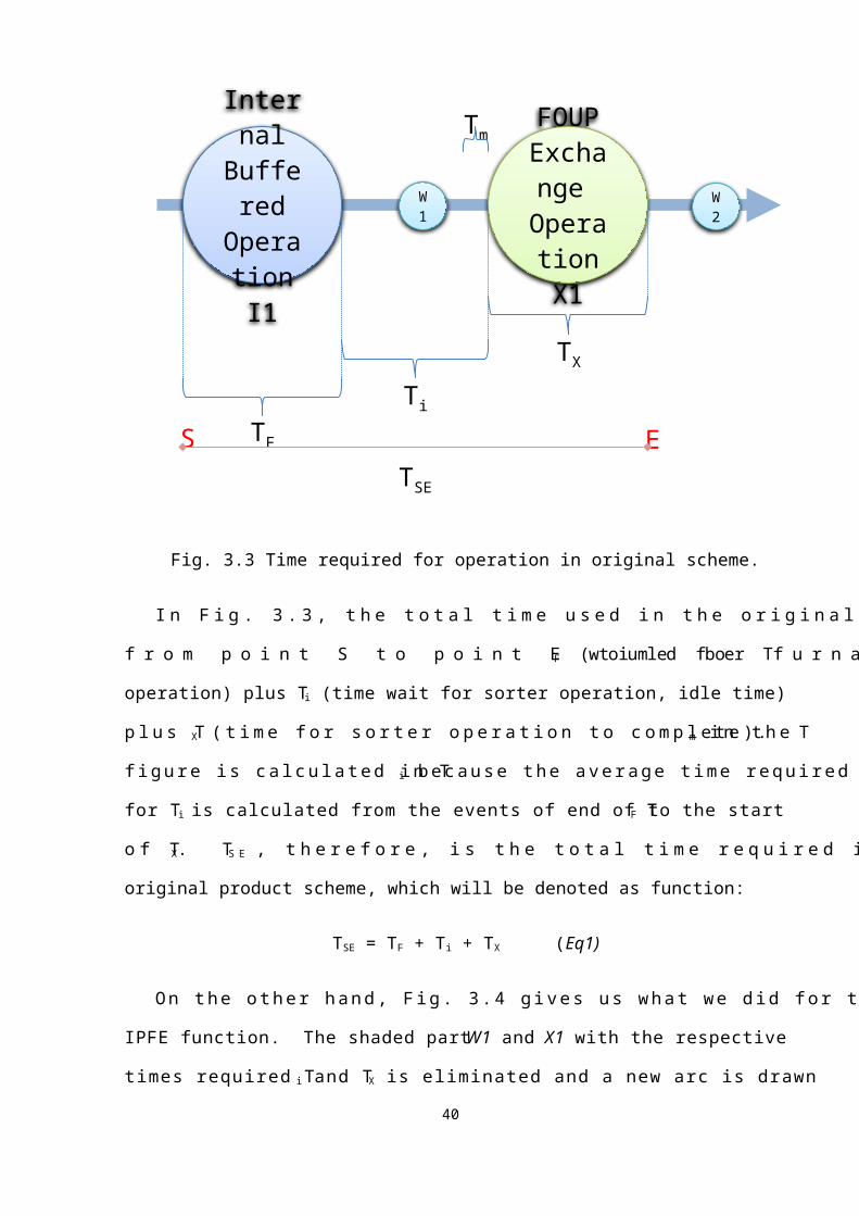
Fig. 3.7 Flow chart of IPFE function applied but failed to take place.
We can see that because the IPFE function failed to take place inside the furnace
operation, the original operation, the sorter operation, must be performed. This is the worst
case of what would happen even if the IPFE function is applied but failed to operate in the
simulation. The time measured in this experiment would also be TSE’, and it is compared
with the original experiment, case of Fig. 3.5(a), again. The comparison graph is in Fig.
3.8.
The purpose of doing the experiment of Fig. 3.7 is because we have to make sure that
even with the new IPFE function applied to the FAB, the original scheme of the process
must still work properly. As the result of Fig. 3.8 shows, the new IPFE function will not
40

make a difference if it had failed to operate.
Fig. 3.8 IPFE function failed to operate compared with original case of Fig. 3.5(a).
Furthermore, since the function worked properly, we have added a few more checks and
algorithms in the MES program such that the decision of whether IPFE is necessary. This
decision making function will be discussed more in detail in the next chapter. We can see that
the improvement does not seem to be so effective when the stocker failure rate is high even
with the IPFE function had implied but it does not affect the original process scheme.
In the next chapter, we will not only discuss the new MES algorithm but also how the
IPFE function may benefit the traffic of the semiconductor manufacturing.
41

Chapter 4 Data Analysis and Comparison
We have introduced the IPFE function and successfully implemented it in a
semiconductor manufacturing automation simulation and the result was as expected. In this
chapter, we will discuss in detail the results obtained from the previous chapter. In section 4-
1, we will begin with the data collected as a baseline for comparison and discuss what would
the IPFE function affect on the collected data. Section 4-2 describes the decision
methodology of MES. After that, section 4-3 discusses how the IPFE function has relaxed
the WIP of the original sorter operations.
4-1 Collected Data Interpretation
Let us take a look at the data we have monitored in a DRAM manufacturing company.
The sample product we looked for is a main product that consumes 30% of the company’s
production line. There are more than 800 operations in manufacturing this DRAM product.
Within these 800 operations, we have found five pairs of the operations that may be similar to
Fig. 3.1 and these ten operations may be the candidate for the IPFE function to take place.
We will label these five pairs of operations AI1, AX1, BI1, BX1, CI1, CX1, DI1, DX1, EI1,
and EX1 by which the “I” operations stand for lots to be processed in internal buffered
equipment and the “X” operations are those for lots to be processed in a sorter equipment. In
other words, the AI1 ~ EI1 operations requires sorter operations, AX1 ~ EX1, after the lots
have completed their process in their respective internal buffered equipments. Among the
five pairs of the internal buffered operations mentioned above, some of the operations are Wet
operations. Wet operations are operations that consist of sinking the entire lot into a tank full
of liquid. Most of these operations are for cleaning purposes and FOUP exchange operations
are usually required after the lots being cleaned. In this operation, the equipment used are
42

categorized as internal buffered equipments as well because these equipments have also the
internal shelves to place the FOUPs and can process 2 lots at a time with all the wafers of
these 2 lots unloaded from the FOUPs into a tank. The entire process elapses for
approximately 2 hours. The five pairs of operations we have selected here in this thesis
contain two Wet operations. Further down in the thesis, we will briefly discuss about the Wet
equipment. Table 4.1 shows the average time measured in minutes a lot needed to wait from
finished process of nI1 to start of nX1 for 3000 lots of the same DRAM product where “n”
stands for A ~ E from the previous descriptions.
Table 4.1 Time waited in minutes from end of an internal buffered equipment to start of
a sorter process.
A B C D EnI1 ~ nX1 69.37 105.8 45.56 96.1 143.23
nX1 3.18 2.98 3.52 3.18 3.61Total 72.55 108.78 49.08 99.28 146.84Flow Total 476.53
The total time for the entire process flow to finish from the Table 4.1 would require
476.53 minutes in average and that is 0.33 day.
From the experiment we did in chapter 3, we have successfully by-passed all the five
pairs of the operations AX1 ~ EX1 in a simulated environment. Therefore, the idle time the
LOTs waited to be processed in FOUP exchange operations after finishing the I-operations
were saved as well as the time that may be needed for the actual FOUP exchange operations.
As we have mentioned in chapter 3, we simulated the cases to make the IPFE function to
work. We then tested the IPFE function again with different cases of FOUP transfer delays.
43

This is because in the actual semiconductor manufacturing process, FOUP transportation is a
critical issue. We can see from Table 4.2, we tested four major delay cases. The first delay
group is randomized from 5 to 10 minutes. The second group is from 10 to 15 minutes. The
third group is from 15 to 20 minutes. And the last group is the randomized time beyond 20
minutes of transfer delay. As from the third group, the hit rate of the IPFE function was 97%.
This means that in 25 batches of 100 lots, 3 lots will fail to perform the IPFE function. If set
the delay to 20 minutes and beyond as the lst group, the hit rate of the IPFE function would
drop to 86%. This means that 16 lots failed to perform the IPFE function.
Table 4.2 Hit rate of IPFE function with FOUP transfer time considered.
FOUP transfer time (min) 5~10 10~15 15~20 20~be
yondIPFE Success rate 100% 100% 97% 84%
We have mentioned earlier in chapter 2 how internal buffered processes take place for
furnace equipments (Fig 2.5). We would briefly describe how the process takes place for Wet
equipments. This operation requires a batch of 2 lots takes approximately 2 hours to
complete and the lots are to be run in a sink as demonstrated in Fig. 4.1.
44

Fig. 4.1 Wet equipment.
Before we move on to the next section, we can summarize what we have done so far.
We have tested all the cases with the application of IPFE function and discovered that some
cycle time of a certain product may be reduced. We have tried the IPFE function with its best
cases as well as worst cases and in addition with some delays of FOUP transportations to
make it similar to that of the FAB scenario. As we have noticed that the changes for the
software above to fit the IPFE function is based on TCS and EAP. In the next section, we
will discuss some detailed changes in the MES of how we make the decision of which empty
FOUP to be assigned.
4-2 Decision Model in MES
In the inquiry transaction “T7” of Fig. 3.2, TCS demands a new empty FOUP from
MES, the check diagram is as shown in Fig. 4.2.
45
Load Port 2
Load Port 1
FOUPs are loaded to internal
shelves first All wafers loaded into
tank
shelf

Fig. 4.2 MES request empty FOUP transaction logic.
From the diagram, the first part is to find the available stockers and then calculate the
transport time required. The transportation time is calculated by a new table in the database
to judge whether to transport a new FOUP or not, i.e. by checking the transfer command
queue of the stocker as well as the FOUPs being transferred occupies the route from stocker
to the desired internal buffered equipment. This could be done by a reply of “traffic report”5
from MCS. After checking the requirements, MES would return an appropriate FOUP for
TCS to reserve. In this case, if the result of MES is to transfer the new FOUP and an
additional “transfer reserve” action takes place to prevent any other systems or users may
take the reserved FOUP. This newly reserved FOUP would only begin its transfer when the
old FOUP on the equipment starts to leave. This asynchronous transfer has two main
reasons: 1. to make sure that there are enough and available empty shelf inside the
55 The traffic report of MCS is a transaction that MES request to MCS, if this transaction is not available or has timed-out, MES will simply assume that the route from stocker to equipment is free of traffic.
46
Incoming transaction from TCS Check
closest nearby stockerEstimate
transport trafficSelect
appropriate
FOUP
Find next
nearby stocker
Check other
stockers
Return original FOUP
Transport reserve &
return transaction
Outgoing transaction to TCS
YES: NO:

equipment; 2. the load port of the equipment is not occupied. On the other hand, if no
appropriate FOUP was found and old FOUP ID was returned from MES, TCS will skip this
LOT and check again for the next LOT in the batch.
It is quite different though, from the dispatching logic view of neither by LOT nor by
equipment since what we tried to do was to “steal” the time while the wafers are being
processed and the dispatching logic is based on empty FOUPs and stockers. Therefore, all
the jobs in the IPFE function must act in an asynchronous behavior depending on whether the
wafers have been started to process.
The final change to MES was when all the LOTs in the batch have completed their
process. The transaction that handles this action is called “Operation Complete”. Since the
control job of a batch is the same, MES has to judge which of the lots have used IPFE
function and which lots have not. In the original computer integrated manufacturing (CIM)
framework, the control job information was kept only in between TCS and EAP. But when it
comes to the IPFE case, MES must need to know whether the attributes of the control job
have been changed.
47
Operation Complete TransactionOperation
CompleteOperati
on Complet
e
FOUP exchang
e
Operation
Locate
Original input + new parameters

Fig. 4.3 Re-wrapped “Operation Complete” transaction of MES.
Therefore, we have re-wrapped the “Operation Complete” transaction as in Fig. 4.3 such
that MES must judge with the additional information, that whether further operations for the
LOT in the batch are required. These operations include “FOUP exchange operation” and
“Operation Locate” operation. “Operation Locate” is a transaction that sets a lot to a desired
operation of a product flow directly.
Having discussed the changes and decision logic in MES, we will move on to the next
section of how the IPFE function would affect the traffic of the FAB.
4-3 Benefits
After we have successfully implemented the IPFE function in the test environment, we
extended more simulation models to observe what would this function may benefit the entire
FAB. The model was to adapt one major product, named product B, and the rest of the
products categorized as others, named product C, into the simulation and tested for 24 hours.
We observed the amount of wafers work in process (WIP) that are idle (wait for sorter
operation) in the first day and re-run the same scenario with IPFE function applied for
another 24 hours. The IPFE function was only applied for the product we have mentioned,
named product A, which occupies 30% of the DRAM company’s production line. Within
product A, the entire process consists of 11 FOUP exchange operations and only 5 of them
could apply the IPFE function. We can see from Fig. 4.4 that the WIP idle was decreased
because 5 of the sorter operations were no longer needed. The improvement of wafers being
idle was by 7.84% in average.
48

Fig. 4.4 Effect of WIP idle (waiting) for sorter operation.
Furthermore, Fig. 4.5(a) shows the WIP status before IPFE applied to product A and Fig.
4.5(b) shows the WIP after IPFE applied to product A. We can see that the WIP of product A
had decreased and there was an increase of WIP for both product B and product C. This
indicates that with the same amount of time provided for the same amount of wafers to
process, the IPFE function would enhance the sorter to operate more jobs for other products.
This would result in a shortening of cycle time for not only product A but also the cycle time
of other products.
49

Fig. 4.5(a) WIP status for products before IPFE.
50
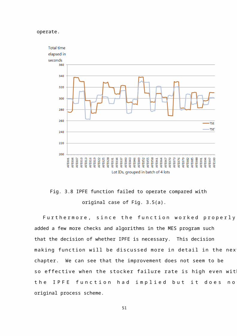
Fig. 4.5(b) WIP status for products after IPFE.
The last topic we would like to discuss before we finish is the occupation rate of the
stockers. In the automation process, the equipments would assign one or more of their
nearby stockers such that the transfer time of the FOUPs could be reduced to minimum.
Since sorters are busy around the clock, their nearby stockers’ occupation rates are usually
high, more than 90%. One main reason is because these stockers may have to store empty
FOUPs as well as FOUPs containing products for exchange operations. On the other hand,
the nearby stockers of the internal buffered equipments do not have a high occupation rate,
50% ~70%. With the IPFE function applied, we can store some of the empty FOUPs in these
stockers and hence balance the stocker occupation rate. This is significant because if the
FOUPs are well balanced in the FAB, the traffic of the FAB would be balanced as well.
However, we have not actually tested and monitored the traffic control of the FAB since we
51

cannot apply the function onto the production environment to see the transportation status
because a minor bug in the program may cause the entire FAB to halt.
To conclude this chapter, we have explained the model being used in MES and
monitored the benefits to the WIP for the FAB which may maximize the throughput of the
semiconductor manufacturing.
Chapter 5 Conclusion
In semiconductor manufacturing, cycle time (CT) has always been a competitive
challenge. With the assistance of the new SEMI standard, we introduced a new function
called In-Process FOUP Exchange (IPFE) that would “steal” some of the processing time in
semiconductor manufacturing. We have assumed that with the IPFE function introduced, we
could by-pass some of the operations in manufacturing an integrated circuit (IC). In this
thesis, we have applied the changes in the related systems in an automated 300mm FAB and
simulated the experiment. The results of the experiments proved that the IPFE function may
benefit the cycle time of semiconductor manufacturing.
However, there would be a lot more challenges if we would actually apply the IPFE
function onto production. The main reason is that not all the equipments in the company
could support the specification standard that has been decided in SEMI E94-1107. This is
52

because the functions in a semiconductor factory must be decided before building the actual
factory. With each function added or requested, the equipment vendors and factory engineers
must apply a full function test to the equipments before deploying to the factory production
line. This is critical because the cost of manufacturing these integrated circuits are high and
the delivery time for customers is important.
The other potential issue we cannot test in the experiment is that there may be some
materials or metallic vapor contaminated inside the internal buffered equipments that would
actually pollute the new FOUPs transferred for the IPFE function. On the other hand, there
are some other operations that require FOUP exchange operations but were not defined in the
process flow. These operations do not have contamination concerns but may require
additional calculations on site by which other software applications, such as watchdog
servers, may have to be created.
As conclusion, the experiment supports that IPFE function would be worth being
implemented in a modern FAB since it not only could reduce the cycle time of a single
product, but also help to shorten the cycle time of the other products. In addition, the
transportation traffic can also be integrated. However, with all the changes we may think of
to enhance semiconductor manufacturing, we still have to monitor the behavior of
infrastructure because trillions of transactions take place in a 120K FAB. Once the CPU
loading or software threads start to suffer in the FAB, the entire production line may result a
hang and deadlocks may occur. These concerns could be the considerations while a company
tries to expand and we hope that this thesis may be a good reference for automation design in
semiconductor manufacturing in the coming future.
53

References[1] Y.C. Wang, D. Ho, C.S. Wu, L. jann, “Sorter Automatic Operations in A 300 mm
FAB”, Semiconductor Manufacturing Technology Workshop 2002[2] SEMI E94.1-1107 Specification for SECS-II Protocol for Control Job Management
(CJM), http://www.semi.org.[3] C. Maxim, R. Goss, D. Adhikari, J. Rothe, M. Drozda, “Manufacturing
Optimization Improvements Leveraging SEMI E94-1107”, Advanced Semiconductor Manufacturing Conference, 2009. ASMC '09. IEEE/SEMI.
[4] C. Maxim, R. Goss, D. Adhikari, J. Rothe, M. Drozda, “Enablin Material Redirection in the Next-Generation Factory”, Future Fab International, July 2009, pp48 – 53.
[5] D.L. Wu, H.L. Lo, C.C. Pan, Y.T. Chang, C.L. Peng, “Automatically Form Batch via Real Time Dispatch for Furnace Operation in 300 mm FAB”, Semiconductor Manufacturing Technology Workshop Proceedings, 2004, pp29 – 32.
[6] SEMI E94-0309 Specification for Control Job Management (CJM), http://www.semi.org.
[7] SEMI E39-0703 Specification for Object Services Standard: Concepts, Behavior, and Services, http://www.semi.org.
[8] SEMI E39.1-0703 Specification for Object Services Standard, http://www.semi.org.
54

Appendix A: List of acronymsAMHS Automated Material Handling SystemAPC Advance Process ControlCIM Computer Integrated ManufacturingCJ Control JobCMOS Complementary Metal-Oxide-SemiconductorCT Cycle TimeDRAM Dynamic Random Access MemoryEAP Equipment Automation ProgramFOUP Front Opening Unified PodIC Integrated CircuitIPFE In-Process FOUP ExchangeMCS Material Control SystemMES Manufacturing Execution SystemOHT Overhead Hoist TransportPJ Process JobRTD Real-Time DispatchSPC Statistical Process ControlTCS Tool Control SystemWIP Work-In-Process
55

Biography
Shen-Chia (Jack) Yang graduated from National Chiao Tung University, Hsin-Chu,
Taiwan in the year of 2003 majored in Computer Science and Information Technology. Jack
served the compulsory military service in Taiwan and assisted to translate a text book while
served in the Army. He finished the service and started to work for Powerchip
Semiconductors Corporation in May 2005. Jack works as a senior engineer in the
Automation Department of the company
56