sizing calculations rw cw hd ad
DESCRIPTION
CHEMICAL-DOSING-PLANTS-TRANSCRIPT
Prepared By: BhaveshDate: 9th May, 2011
Checked by:NMK
REV NO. - 00
Project
Owner
Contractor
Consultant
System
System supplier
Document No.
Ref Drwg / Doc. 12 Technical Specification # SPML-S10IRJ01-DD-ME-009 for CW Chlorination Plant
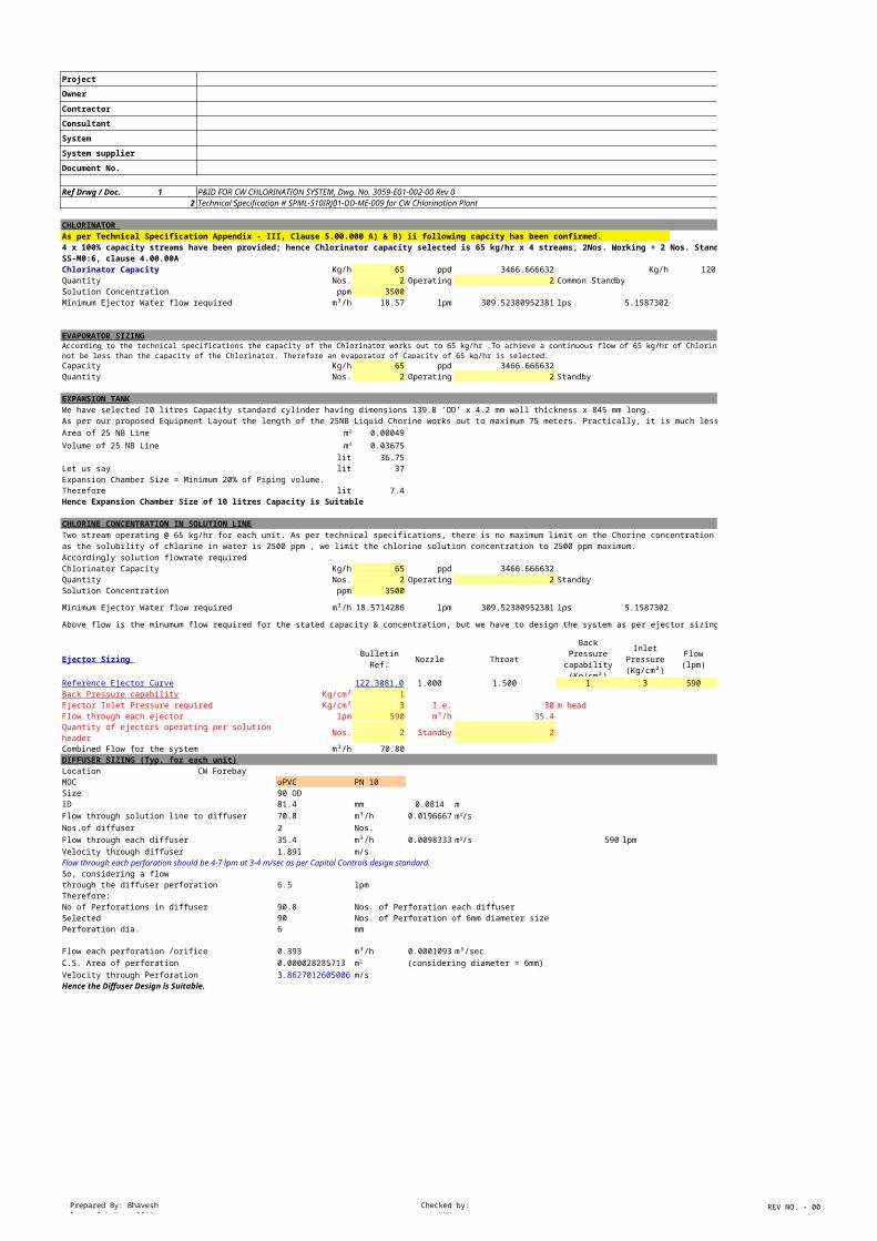
CHLORINATOR As per Technical Specification Appendix - III, Clause 5.00.000 A) & B) ii following capcity has been confirmed.
4 x 100% capacity streams have been provided; hence Chlorinator capacity selected is 65 kg/hr x 4 streams, 2Nos. Working + 2 Nos. Stand by as per specification, sheet SS-M0:6, clause 4.00.00A
Kg/h 65 ppd 3466.666632 Kg/h 120 Rated capacityQuantity Nos. 2 Operating 2 Common Standby Solution Concentration ppm 3500Minimum Ejector Water flow required m³/h 18.57 lpm 309.52380952381 lps 5.15873016
EVAPORATOR SIZING
Capacity Kg/h 65 ppd 3466.666632Quantity Nos. 2 Operating 2 Standby
EXPANSION TANKWe have selected 10 litres Capacity standard cylinder having dimensions 139.8 ’OD’ x 4.2 mm wall thickness x 845 mm long.As per our proposed Equipment Layout the length of the 25NB Liquid Chorine works out to maximum 75 meters. Practically, it is much less.Area of 25 NB Line 0.00049
Volume of 25 NB Line 0.03675lit 36.75
Let us say lit 37Expansion Chamber Size = Minimum 20% of Piping volume.Therefore lit 7.4Hence Expansion Chamber Size of 10 litres Capacity is Suitable
CHLORINE CONCENTRATION IN SOLUTION LINE
Accordingly solution flowrate required Chlorinator Capacity Kg/h 65 ppd 3466.666632Quantity Nos. 2 Operating 2 StandbySolution Concentration ppm 3500
Minimum Ejector Water flow required m³/h 18.57142857 lpm 309.52380952381 lps 5.15873016
Above flow is the minumum flow required for the stated capacity & concentration, but we have to design the system as per ejector sizing
Ejector Sizing Bulletin Ref. Nozzle Throat Flow (lpm) Flow m³/h
122.3081.0 1.000 1.500 1 3 590 35.4Kg/cm² 1
Ejector Inlet Pressure required Kg/cm² 3 I.e. 30 m headFlow through each ejector lpm 590 m³/h 35.4
Quantity of ejectors operating per solution header Nos. 2 Standby 2
Combined Flow for the system m³/h 70.80DIFFUSER SIZING (Typ. for each unit)Location CW Forebay MOC uPVC PN 10Size 90 ODID 81.4 mm 0.0814 mFlow through solution line to diffuser 70.8 m³/h 0.01966667Nos.of diffuser 2 Nos.Flow through each diffuser 35.4 m³/h 0.00983333 590 lpmVelocity through diffuser 1.891 m/sFlow through each perforation should be 4-7 lpm at 3-4 m/sec as per Capital Controls design standard.So, considering a flowthrough the diffuser perforation 6.5 lpmTherefore:No of Perforations in diffuser 90.8 Nos. of Perforation each diffuserSelected 90 Nos. of Perforation of 6mm diameter sizePerforation dia. 6 mm
Flow each perforation /orifice 0.393 m³/h 0.0001093 m³/secC.S. Area of perforation 0.000028285713 (considering diameter = 6mm) Velocity through Perforation 3.86270126050064 m/sHence the Diffuser Design is Suitable.
P&ID FOR CW CHLORINATION SYSTEM, Dwg. No. 3059-E01-002-00 Rev 0
Chlorinator Capacity
According to the technical specifications the capacity of the Chlorinator works out to 65 kg/hr .To achieve a continuous flow of 65 kg/hr of Chlorine Gas; the evaporator capacity should not be less than the capacity of the Chlorinator. Therefore an evaporator of Capacity of 65 kg/hr is selected.
m2
m3
Two stream operating @ 65 kg/hr for each unit. As per technical specifications, there is no maximum limit on the Chorine concentration in the solution line. However, as the solubility of chlorine in water is 2500 ppm , we limit the chlorine solution concentration to 2500 ppm maximum.
Back Pressure capability (Kg/cm²)
Inlet Pressure (Kg/cm²)
Reference Ejector CurveBack Pressure capability
m3/s
m3/s
m2
Prepared By: BhaveshDate: 9th May, 2011
Checked by:NMK
REV NO. - 00
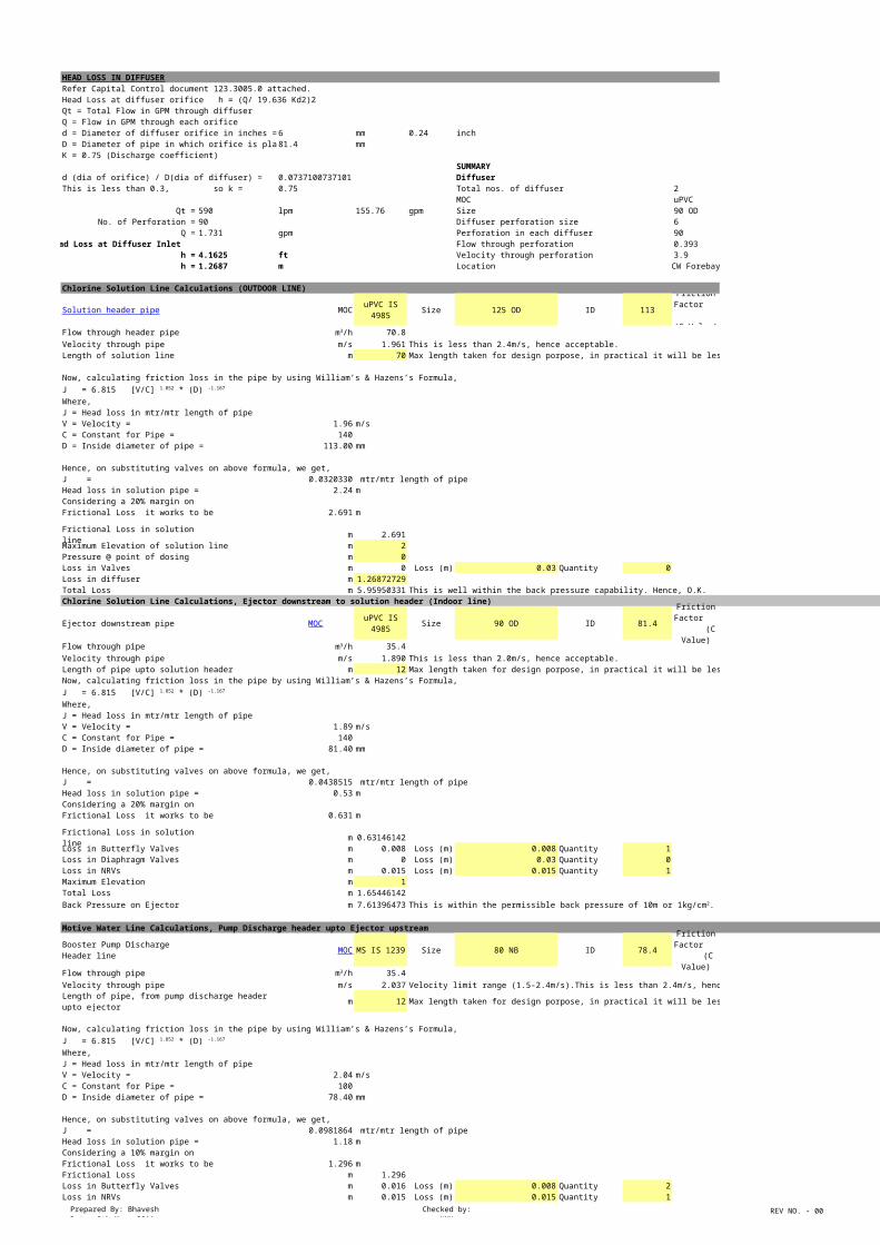
HEAD LOSS IN DIFFUSERRefer Capital Control document 123.3005.0 attached.Head Loss at diffuser orifice h = (Q/ 19.636 Kd2)2 Qt = Total Flow in GPM through diffuserQ = Flow in GPM through each orificed = Diameter of diffuser orifice in inches = 6 mm 0.24 inchD = Diameter of pipe in which orifice is placed = 81.4 mmK = 0.75 (Discharge coefficient)
SUMMARYd (dia of orifice) / D(dia of diffuser) = 0.073710073710074 DiffuserThis is less than 0.3, so k = 0.75 Total nos. of diffuser 2 Nos.
MOC uPVC PN 10Qt = 590 lpm 155.76 gpm Size 90 OD
No. of Perforation = 90 Diffuser perforation size 6 mmQ = 1.731 gpm Perforation in each diffuser 90 Nos.
Head Loss at Diffuser Inlet Flow through perforation 0.393 m³/h h = 4.1625 ft Velocity through perforation 3.9 m/s h = 1.2687 m Location CW Forebay
Chlorine Solution Line Calculations (OUTDOOR LINE)
MOC uPVC IS 4985 Size 125 OD ID 113 140
Flow through header pipe 70.8Velocity through pipe m/s 1.961 This is less than 2.4m/s, hence acceptable.Length of solution line m 70 Max length taken for design porpose, in practical it will be less.
Now, calculating friction loss in the pipe by using William’s & Hazens’s Formula,
Where,J = Head loss in mtr/mtr length of pipe V = Velocity = 1.96 m/sC = Constant for Pipe = 140D = Inside diameter of pipe = 113.00 mm
Hence, on substituting valves on above formula, we get,J = 0.0320330 mtr/mtr length of pipeHead loss in solution pipe = 2.24 mConsidering a 20% margin on Frictional Loss it works to be 2.691 m
Frictional Loss in solution line m 2.691Maximum Elevation of solution line m 2Pressure @ point of dosing m 0Loss in Valves m 0 Loss (m) 0.03 Quantity 0Loss in diffuser m 1.268727286Total Loss m 5.959503309 This is well within the back pressure capability. Hence, O.K.Chlorine Solution Line Calculations, Ejector downstream to solution header (Indoor line)
Ejector downstream pipe uPVC IS 4985 Size 90 OD ID 81.4 140
Flow through pipe 35.4Velocity through pipe m/s 1.890 This is less than 2.0m/s, hence acceptable.Length of pipe upto solution header m 12 Max length taken for design porpose, in practical it will be less.Now, calculating friction loss in the pipe by using William’s & Hazens’s Formula,
Where,J = Head loss in mtr/mtr length of pipe V = Velocity = 1.89 m/sC = Constant for Pipe = 140D = Inside diameter of pipe = 81.40 mm
Hence, on substituting valves on above formula, we get,J = 0.0438515 mtr/mtr length of pipeHead loss in solution pipe = 0.53 mConsidering a 20% margin on Frictional Loss it works to be 0.631 m
Frictional Loss in solution line m 0.631461425Loss in Butterfly Valves m 0.008 Loss (m) 0.008 Quantity 1Loss in Diaphragm Valves m 0 Loss (m) 0.03 Quantity 0Loss in NRVs m 0.015 Loss (m) 0.015 Quantity 1Maximum Elevation m 1Total Loss m 1.654461425Back Pressure on Ejector m 7.613964734
Motive Water Line Calculations, Pump Discharge header upto Ejector upstream
Booster Pump Discharge Header line MS IS 1239 Size 80 NB ID 78.4 100
Flow through pipe 35.4Velocity through pipe m/s 2.037 Velocity limit range (1.5-2.4m/s).This is less than 2.4m/s, hence acceptable.
Length of pipe, from pump discharge header upto ejector m 12 Max length taken for design porpose, in practical it will be less.
Now, calculating friction loss in the pipe by using William’s & Hazens’s Formula,
Where,J = Head loss in mtr/mtr length of pipe V = Velocity = 2.04 m/sC = Constant for Pipe = 100D = Inside diameter of pipe = 78.40 mm
Hence, on substituting valves on above formula, we get,J = 0.0981864 mtr/mtr length of pipeHead loss in solution pipe = 1.18 mConsidering a 10% margin on Frictional Loss it works to be 1.296 mFrictional Loss m 1.296Loss in Butterfly Valves m 0.016 Loss (m) 0.008 Quantity 2Loss in NRVs m 0.015 Loss (m) 0.015 Quantity 1
Solution header pipeFriction
Factor (C Value)
m3/h
J = 6.815 [V/C] 1.852 * (D) -1.167
MOCFriction
Factor (C Value)
m3/h
J = 6.815 [V/C] 1.852 * (D) -1.167
This is within the permissible back pressure of 10m or 1kg/cm2. Hence, O.K.
MOCFriction
Factor (C Value)
m3/h
J = 6.815 [V/C] 1.852 * (D) -1.167
Prepared By: BhaveshDate: 9th May, 2011
Checked by:NMK
REV NO. - 00
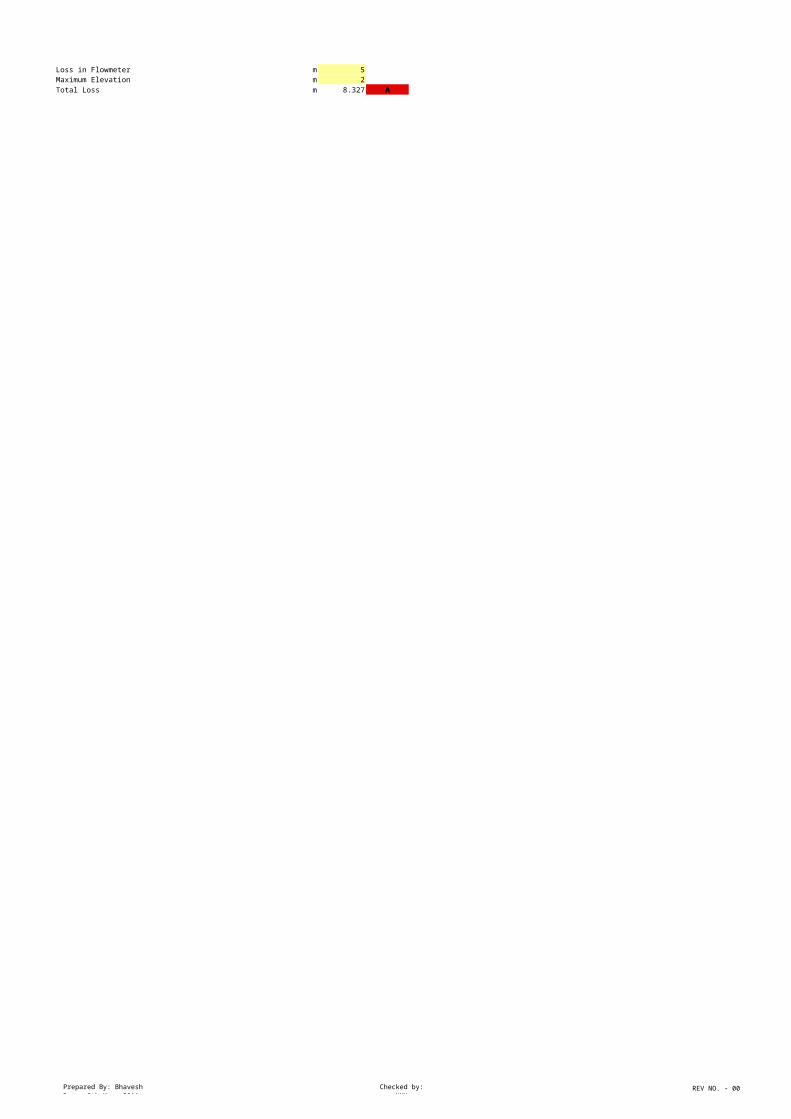
Loss in Flowmeter m 5Maximum Elevation m 2Total Loss m 8.327 A

Prepared By: BhaveshDate: 9th May, 2011
Checked by:NMK
REV NO. - 00
Motive Water Line Calculations, Pump Discharge line upto Discharge header
Booster Pump Discharge line MS IS 1239 Size 100 NB ID 102.3 100
Flow through pipe 70.80Velocity through pipe m/s 2.393 Velocity limit range (3m/s). This is less than 3m/s, hence acceptable.
Length of pipe, from pump discharge header upto ejector m 12 Max length taken for design porpose, in practical it will be less.
Now, calculating friction loss in the pipe by using William’s & Hazens’s Formula,
Where,J = Head loss in mtr/mtr length of pipe V = Velocity = 2.39 m/sC = Constant for Pipe = 100D = Inside diameter of pipe = 102.30 mm
Hence, on substituting valves on above formula, we get,J = 0.0969769 mtr/mtr length of pipeHead loss in solution pipe = 1.16 mConsidering a 10% margin on Frictional Loss it works to be 1.280 mFrictional Loss m 1.280Loss in Butterfly Valves m 0.008 Loss (m) 0.008 Quantity 1Loss in NRVs m 0.015 Loss (m) 0.015 Quantity 1Total Loss m 1.303 B
Pressure required @ pump discharge 39.6 Ejector Inlet pressure +A + B X 10%Margin
Motive Water Line Calculations, motive water header
Booster pump suction line MS IS 1239 Size 125 NB ID 129.5 100
Flow through pipe 70.80Velocity through pipe m/s 1.493 Velocity limit range (1.5m/s). This is less than 1.5m/s, hence acceptable.
m 12 Max length taken for design porpose, in practical it will be less.
Now, calculating friction loss in the pipe by using William’s & Hazens’s Formula,
Where,J = Head loss in mtr/mtr length of pipe V = Velocity = 1.49 m/sC = Constant for Pipe = 100D = Inside diameter of pipe = 129.50 mm
Hence, on substituting valves on above formula, we get,J = 0.0307543 mtr/mtr length of pipeHead loss in solution pipe = 0.37 mConsidering a 10% margin on Frictional Loss it works to be 0.406 m
Frictional Loss m 0.406Loss in Butterfly Valves m 0.0025 Loss (m) 0.0025 Quantity 1Total Loss m 0.408457316 C
Motive Water Line Calculations, motive water header from tapping point upto pump suction line
Booster pump suction Header MOC MS IS 1239 Size 100 NB ID 104.2 100
Flow through pipe 70.8Velocity through pipe m/s 2.306 Velocity limit range (1.5-2.4m/s). This is less than 2.4m/s, hence acceptable.
Length of pipe from tapping point m 10 Max length taken for design porpose, in practical it will be less.
Now, calculating friction loss in the pipe by using William’s & Hazens’s Formula,
Where,J = Head loss in mtr/mtr length of pipe V = Velocity = 2.31 m/sC = Constant for Pipe = 100D = Inside diameter of pipe = 104.20 mm
Hence, on substituting valves on above formula, we get,J = 0.0886623 mtr/mtr length of pipeHead loss in solution pipe = 0.89 mConsidering a 10% margin on Frictional Loss it works to be 0.975 m
Frictional Loss m 0.975Maximum Elevation m 2Loss in Butterfly Valves m 0.024 Loss (m) 0.008 Quantity 3Loss in Strainers @ 50% choked condition m 5 Loss (m) 5 Quantity 1Total Loss m 7.999284921 D
m 8.407742237 C+DWater Pressure available at tapping point m 0Head available @ pump suction m -8.4
SUMMARYPipe
Location Pipe MOC Selected Size ID (mm) Velocity m/s Velocity Limit Remark
Booster Pump Suction Line MS IS 1239 70.8 100 NB 104.2 2.31 2.4
Booster Pump Suction Header MS IS 1239 70.8 125 NB 129.5 1.49 1.5
Booster Pump Discharge Line MS IS 1239 70.8 100 NB 102.3 2.39 3
Ejector Upstream MS IS 1239 35.4 80 NB 78.4 2.04 2.4
Chlorine Solution Line at ejector outlet uPVC IS 4985 35.4 90 OD 81.4 1.89 2.0
Chlorine Solution Header Line uPVC IS 4985 70.8 125 OD 113 1.96 2.4
MOCFriction
Factor (C Value)
m3/h
J = 6.815 [V/C] 1.852 * (D) -1.167
Total Discharge Head (m)
MOCFriction
Factor (C Value)
m3/h
Length of pipe from header upto pump suction
J = 6.815 [V/C] 1.852 * (D) -1.167
Friction Factor (C
Value)
m3/h
J = 6.815 [V/C] 1.852 * (D) -1.167
Total Loss in Motive Water Pipe from tapping point upto pump suction
Flow m3/h
This
with
in v
eloc
ity li
mit,
hen
ce
sele
cted
line
siz
e is
ok
Prepared By: BhaveshDate: 17th May, 2011
Checked by:NMK
REV NO. - 0
Project
Owner
Contractor
Consultant
System
System supplier
Document
Document No.
Ref Drwg / Doc. 12 Technical Specification # SPML-S10IRJ01-DD-ME-009 for RW Chlorination Plant
CHLORINATOR As per Technical Specification following capcity has been confirmed.
2 x 100% capacity streams have been provided; hence Chlorinator capacity selected is 1.5 kg/hr x 2 streams, 1No. Working + 1 No. Stand by as per specification.
Kg/h 1.5 ppd 79.9999992 Kg/h 2 Rated capacity
Quantity Nos. 1 Operating 1 Common Standby Solution Concentration ppm 2500Minimum Ejector Water flow required m³/h 0.60 lpm 10 lps 0.166666667
CHLORINE CONCENTRATION IN SOLUTION LINE
Accordingly solution flowrate required Chlorinator Capacity Kg/h 1.5 ppd 79.9999992Quantity Nos. 1 Operating 1 StandbySolution Concentration ppm 2500
Minimum Ejector Water flow required m³/h 0.6 lpm 10 lps 0.166666667
Above flow is the minumum flow required for the stated capacity & concentration, but we have to design the system as per ejector sizing
Ejector Sizing Bulletin Ref. Nozzle Throat Flow (lpm) Flow m³/h
122.3063.0 12.000 0.000 1.5 4 27 1.62Kg/cm² 1.5
Ejector Inlet Pressure required Kg/cm² 4 I.e. 40 m headFlow through each ejector lpm 27 m³/h 1.62
Quantity of ejectors operating per solution header Nos. 1 Standby 1
Combined Flow for the system m³/h 1.62DIFFUSER SIZING (Typ. for each unit)Location CW Forebay MOC uPVC Sch 80Size 1"ID 24.3 mm 0.0243 mFlow through solution line to diffuser 1.62 m³/h 0.00045Nos.of diffuser 1 Nos.Flow through each diffuser 1.62 m³/h 0.00045 27 lpmVelocity through diffuser 0.970801212 m/sFlow through each perforation should be 4-7 lpm at 3-4 m/sec as per Capital Controls design standard.So, considering a flowthrough the diffuser perforation 6 lpmTherefore:No of Perforations in diffuser 4.5 Nos. of Perforation each diffuserSelected 5 Nos. of Perforation of 6mm diameter sizePerforation dia. 6 mm
Flow through each perforation /orifice 0.32400000 m³/h 0.0000900 m³/secC.S. Area of perforation 0.000028285713 (considering diameter = 6mm) Velocity through Perforation 3.18181832644629 m/sHence the Diffuser Design is Suitable.
HEAD LOSS IN DIFFUSERRefer Capital Control document 123.3005.0 attached.Head Loss at diffuser orifice h = (Q/ 19.636 Kd2)2 Qt = Total Flow in GPM through diffuserQ = Flow in GPM through each orificed = Diameter of diffuser orifice in inches = 6 mm 0.24 inchD = Diameter of pipe in which orifice is placed = 24.3 mmK = 0.75 (Discharge coefficient)
SUMMARYd (dia of orifice) / D(dia of diffuser) = 0.246913580246914 DiffuserThis is less than 0.3, so k = 0.75 Total nos. of diffuser 1 Nos.
MOC uPVC Sch 80Qt = 27 lpm 7.128 gpm Size 1"
No. of Perforation = 5 Diffuser perforation size 6 mmQ = 1.426 gpm Perforation in each diffuser 5 Nos.
Head Loss at Diffuser Inlet Flow through perforation 0.324 m³/h h = 2.8244 ft Velocity through perforation 3.2 m/s h = 0.8609 m Location CW Forebay
Chlorine Solution Line Calculations (OUTDOOR LINE)
MOC Size 1" ID 24.3 140
Flow through header pipe 1.62Velocity through pipe m/s 0.970 This is less than 2.4m/s, hence acceptable.Length of solution line m 24 Max length taken for design porpose, in practical it will be less.
Now, calculating friction loss in the pipe by using William’s & Hazens’s Formula,
Where,J = Head loss in mtr/mtr length of pipe
P&ID FOR CW CHLORINATION SYSTEM, Dwg. No. 3059-E01-001-00 Rev 0
Chlorinator Capacity
Two stream operating @ 65 kg/hr for each unit. As per technical specifications, there is no maximum limit on the Chorine concentration in the solution line. However, as the solubility of chlorine in water is 2500 ppm , we limit the chlorine solution conc
Back Pressure capability (Kg/cm²)
Inlet Pressure (Kg/cm²)
Reference Ejector CurveBack Pressure capability
m3/s
m3/s
m2
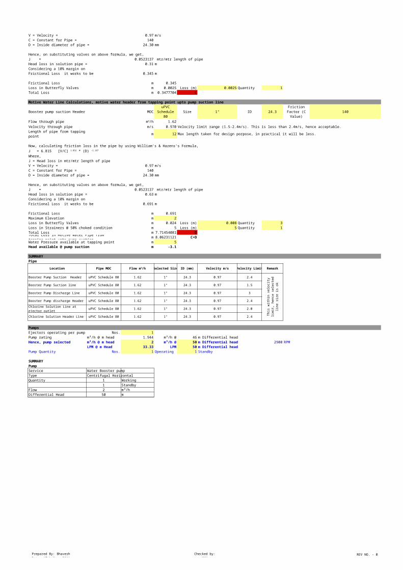
Solution header pipe uPVC Schedule 80
Friction Factor (C Value)
m3/h
J = 6.815 [V/C] 1.852 * (D) -1.167
Prepared By: BhaveshDate: 17th May, 2011
Checked by:NMK
REV NO. - 0
V = Velocity = 0.97 m/sC = Constant for Pipe = 140D = Inside diameter of pipe = 24.30 mm
Hence, on substituting valves on above formula, we get,J = 0.0523137 mtr/mtr length of pipeHead loss in solution pipe = 1.26 mConsidering a 20% margin on Frictional Loss it works to be 1.507 m
Frictional Loss in solution line m 1.507Maximum Elevation of solution line m 2Pressure @ point of dosing m 0Loss in Valves m 0.03 Loss (m) 0.03 Quantity 1Loss in diffuser m 0.860868458Total Loss m 4.397502944 This is well within the back pressure capability. Hence, O.K.Chlorine Solution Line Calculations, Ejector downstream to solution header (Indoor line)
Ejector downstream pipe Size 1" ID 24.3 140
Flow through pipe 1.62Velocity through pipe m/s 0.970 This is less than 2.0m/s, hence acceptable.Length of pipe upto solution header m 12 Max length taken for design porpose, in practical it will be less.Now, calculating friction loss in the pipe by using William’s & Hazens’s Formula,
Where,J = Head loss in mtr/mtr length of pipe V = Velocity = 0.97 m/sC = Constant for Pipe = 140D = Inside diameter of pipe = 24.30 mm
Hence, on substituting valves on above formula, we get,J = 0.0523137 mtr/mtr length of pipeHead loss in solution pipe = 0.63 mConsidering a 20% margin on Frictional Loss it works to be 0.753 m
Frictional Loss in solution line m 0.753317243Loss in Butterfly Valves m 0 Loss (m) 0.008 Quantity 0Loss in Diaphragm Valves m 0 Loss (m) 0.03 Quantity 0Loss in NRVs m 0 Loss (m) 0.015 Quantity 0Maximum Elevation m 1Total Loss m 1.753317243Back Pressure on Ejector m 6.150820187
Motive Water Line Calculations, Pump Discharge header upto Ejector upstream
Booster Pump Discharge Header line Size 1" ID 24.3 140
Flow through pipe 1.62Velocity through pipe m/s 0.970 Velocity limit range (1.5-2.4m/s).This is less than 2.4m/s, hence acceptable.
Length of pipe, from pump discharge header upto ejector m 12 Max length taken for design porpose, in practical it will be less.
Now, calculating friction loss in the pipe by using William’s & Hazens’s Formula,
Where,J = Head loss in mtr/mtr length of pipe V = Velocity = 0.97 m/sC = Constant for Pipe = 140D = Inside diameter of pipe = 24.30 mm
Hence, on substituting valves on above formula, we get,J = 0.0523137 mtr/mtr length of pipeHead loss in solution pipe = 0.63 mConsidering a 10% margin on Frictional Loss it works out to be m 0.691Frictional Loss m 0.691Loss in Butterfly Valves m 0.016 Loss (m) 0.008 Quantity 2Loss in NRVs m 0.015 Loss (m) 0.015 Quantity 1Loss in Flowmeter m 0Maximum Elevation m 2Total Loss m 2.722 A
Motive Water Line Calculations, Pump Discharge line upto Discharge header
Booster Pump Discharge line Size 1" ID 24.3 140
Flow through pipe 1.62Velocity through pipe m/s 0.970 Velocity limit range (3m/s). This is less than 3m/s, hence acceptable.
Length of pipe, from pump discharge header upto ejector m 6 Max length taken for design porpose, in practical it will be less.
Now, calculating friction loss in the pipe by using William’s & Hazens’s Formula,
Where,J = Head loss in mtr/mtr length of pipe V = Velocity = 0.97 m/sC = Constant for Pipe = 140D = Inside diameter of pipe = 24.30 mm
Hence, on substituting valves on above formula, we get,J = 0.0523137 mtr/mtr length of pipeHead loss in solution pipe = 0.31 mConsidering a 10% margin on Frictional Loss it works to be 0.345 mFrictional Loss m 0.345Loss in Butterfly Valves m 0.008 Loss (m) 0.008 Quantity 1
MOC uPVC Schedule 80
Friction Factor (C Value)
m3/h
J = 6.815 [V/C] 1.852 * (D) -1.167
This is within the permissible back pressure of 10m or 1kg/cm2. Hence, O.K.
MOC uPVC Schedule 80
Friction Factor (C Value)
m3/h
J = 6.815 [V/C] 1.852 * (D) -1.167
MOC uPVC Schedule 80
Friction Factor (C Value)
m3/h
J = 6.815 [V/C] 1.852 * (D) -1.167
Prepared By: BhaveshDate: 17th May, 2011
Checked by:NMK
REV NO. - 0
Loss in NRVs m 0.015 Loss (m) 0.015 Quantity 1Total Loss m 0.368 B
Pressure required @ pump discharge 43.1 Ejector Inlet pressure +A + B X 10%Margin
Motive Water Line Calculations, motive water header
Booster pump suction line Size 1" ID 24.3 140
Flow through pipe 1.62Velocity through pipe m/s 0.970 Velocity limit range (1.5m/s). This is less than 1.5m/s, hence acceptable.
m 6 Max length taken for design porpose, in practical it will be less.
Now, calculating friction loss in the pipe by using William’s & Hazens’s Formula,
Where,J = Head loss in mtr/mtr length of pipe V = Velocity = 0.97 m/sC = Constant for Pipe = 140D = Inside diameter of pipe = 24.30 mm
Hence, on substituting valves on above formula, we get,J = 0.0523137 mtr/mtr length of pipeHead loss in solution pipe = 0.31 mConsidering a 10% margin on Frictional Loss it works to be 0.345 m
Frictional Loss m 0.345Loss in Butterfly Valves m 0.0025 Loss (m) 0.0025 Quantity 1Total Loss m 0.347770403 C
Motive Water Line Calculations, motive water header from tapping point upto pump suction line
Booster pump suction Header MOC Size 1" ID 24.3 140
Flow through pipe 1.62Velocity through pipe m/s 0.970 Velocity limit range (1.5-2.4m/s). This is less than 2.4m/s, hence acceptable.
Length of pipe from tapping point m 12 Max length taken for design porpose, in practical it will be less.
Now, calculating friction loss in the pipe by using William’s & Hazens’s Formula,
Where,J = Head loss in mtr/mtr length of pipe V = Velocity = 0.97 m/sC = Constant for Pipe = 140D = Inside diameter of pipe = 24.30 mm
Hence, on substituting valves on above formula, we get,J = 0.0523137 mtr/mtr length of pipeHead loss in solution pipe = 0.63 mConsidering a 10% margin on Frictional Loss it works to be 0.691 m
Frictional Loss m 0.691Maximum Elevation m 2Loss in Butterfly Valves m 0.024 Loss (m) 0.008 Quantity 3Loss in Strainers @ 50% choked condition m 5 Loss (m) 5 Quantity 1Total Loss m 7.714540806 D
m 8.062311209 C+DWater Pressure available at tapping point m 5Head available @ pump suction m -3.1
SUMMARYPipe
Location Pipe MOC Selected Size ID (mm) Velocity m/s Velocity Limit Remark
Booster Pump Suction Header uPVC Schedule 80 1.62 1" 24.3 0.97 2.4
Booster Pump Suction line uPVC Schedule 80 1.62 1" 24.3 0.97 1.5
Booster Pump Discharge Line uPVC Schedule 80 1.62 1" 24.3 0.97 3
Booster Pump discharge Header uPVC Schedule 80 1.62 1" 24.3 0.97 2.4
Chlorine Solution Line at ejector outlet uPVC Schedule 80 1.62 1" 24.3 0.97 2.0
Chlorine Solution Header Line uPVC Schedule 80 1.62 1" 24.3 0.97 2.4
PumpsEjectors operating per pump Nos. 1Pump rating m³/h @ m head 1.944 m³/h @ 46 m Differential headHence, pump selected m³/h @ m head 2 m³/h @ 50 m Differential head 2900 RPM
LPM @ m Head 33.33 LPM 50 m Differential headPump Quantity Nos. 1 Operating 1 Standby
SUMMARYPumpService Water Booster pumpType Centrifugal HorizontalQuantity 1 Working
1 StandbyFlow 2 m³/h Differential Head 50 m
Total Discharge Head (m)
MOC uPVC Schedule 80
Friction Factor (C Value)
m3/h
Length of pipe from header upto pump suction
J = 6.815 [V/C] 1.852 * (D) -1.167
uPVC Schedule 80
Friction Factor (C Value)
m3/h
J = 6.815 [V/C] 1.852 * (D) -1.167
Total Loss in Motive Water Pipe from tapping point upto pump suction
Flow m3/h
This
with
in v
eloc
ity li
mit,
hen
ce
sele
cted
line
siz
e is
ok
ProjectOwnerContractorConsultantSystemSystem supplierDocumentDocument No.
Ref Drwg / Doc. 12
I. STORAGE TANK SIZING:
A. VOLUME CALCULATION FOR SULPHURIC ACID STORAGE TANKQuantity 1 No.Capacity 15 m3
Material of construction: MS as per IS 2062Construction Type: Atmospheric Horizontal cylinder with dished ends
where,Effective volume required: V = 15 cu.m
D= diameter of cylindrical tank 2.5 m ODH= height of cylindrical tank 3.5 m
Calculated volume V = 17.187 m3
B. THICKNESS CALCULATION FOR SULPHURIC ACID STORAGE TANKSMOC: MS as per IS 2062Design Code: IS:803Tank Diameter m 2.5Tank Height m 3.5
1. Shell plate Thickness:The minimum thickness of shell plates shall not be less than the calculations from the folowing formula
T = (50(H-0.3)*D*G/(SE))Where,T= minimum thickness in mmD= Nominal diameter of the tank 2500 mm 2.5 mH= Height from the bottom of the course under consideration to the bottom of the overflow which limits tank filli 3500 mm 3.5 mG = Specific Gravity of liquid to be stored 1.82
1680 kg/cm2E = Joing Efficiency 0.7
Shell Plate Thickness:T = 0.62 mm
Further, we are considering a corrosion allowance = 2 mmTherefore total thickness = 2.62 mm
Selected thickness T = 5 mm
Summary:Construction Atmospheric Horizontal cylinder with dished endsMOC: MS as per IS 2062Thickness 5 mmTank Diameter 2.5 mTank height 3.5 mFree board 0.445 m
II. PIPE SIZING:1. Sulphuric Acid unloading pump Suction header:
MOC: MS IS:1239Size ID in mm ID in metres
65 NB 66.3 0.0663Flow of stream m3/hr 10 0.0028 m3/secVelocity in pump suction header m/sec 0.80
2. Unloading Pump suction line:
MOC: MS IS:1239Size ID in mm ID in metres
65 NB 66.3 0.0663Flow of stream m3/hr 10 m3/sec 0.0028Velocity in pump suction header m/sec 0.80
3. Unloading Pump Discharge Line
MOC: MS IS:1239Size ID in mm ID in metres
50 NB 50.7 0.0507Flow of stream m3/hr 10 m3/sec 0.0028Velocity in pump suction header m/sec 1.38
Volume of tank V=(π/4)x D2 x L
S = Allowable Stress in kg/cm2 for IS:2062 as per clause No. 5 of IS" 803
Hence 5 mm thick plate can be used as per Clause No 6.3.3.2 of IS: 803.
4. Unloading Pump Discharge Header:
MOC: MS IS:1239Size ID in mm ID in metres
50 NB 50.7 0.0507Flow of stream m3/hr 10 m3/sec 0.0028Velocity in pump suction header m/sec 1.38
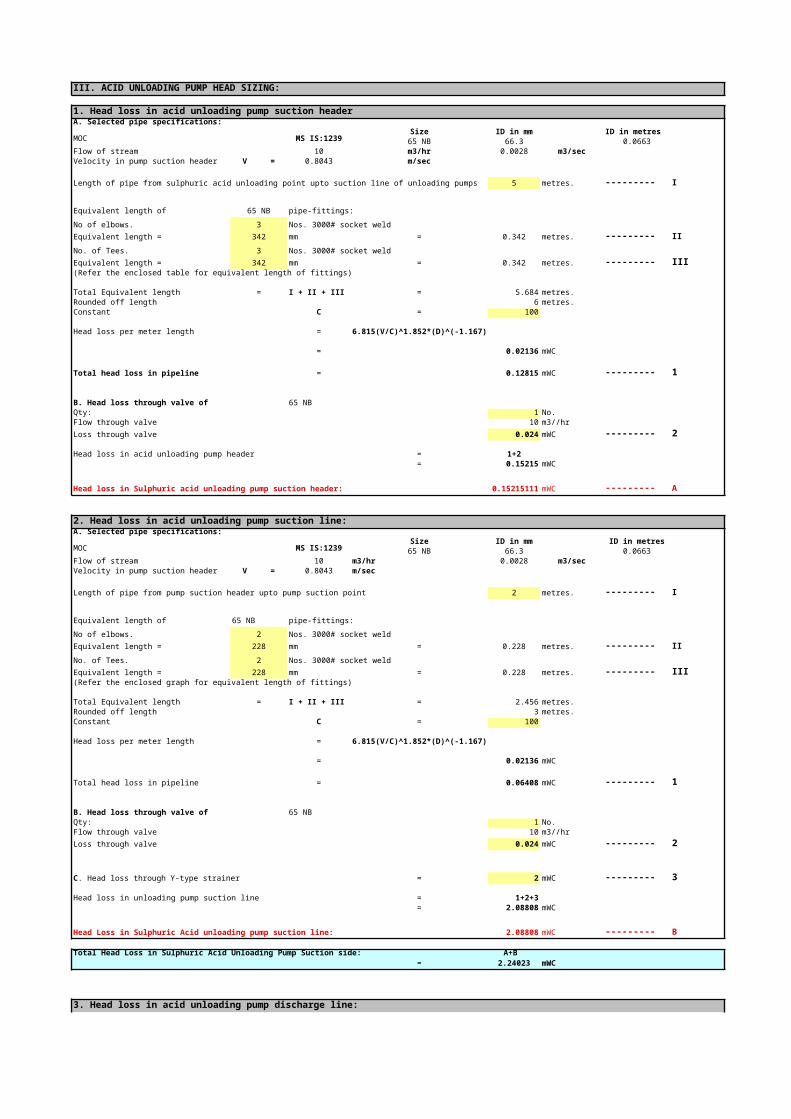
III. ACID UNLOADING PUMP HEAD SIZING:
1. Head loss in acid unloading pump suction headerA. Selected pipe specifications:
MOC MS IS:1239Size ID in mm ID in metres
65 NB 66.3 0.0663Flow of stream 10 m3/hr 0.0028 m3/secVelocity in pump suction header V = 0.8043 m/sec
Length of pipe from sulphuric acid unloading point upto suction line of unloading pumps 5 metres. --------- I
Equivalent length of 65 NB pipe-fittings:
No of elbows. 3 Nos. 3000# socket weld
Equivalent length = 342 mm = 0.342 metres. --------- II
No. of Tees. 3 Nos. 3000# socket weld
Equivalent length = 342 mm = 0.342 metres. --------- III(Refer the enclosed table for equivalent length of fittings)
Total Equivalent length = I + II + III = 5.684 metres.Rounded off length 6 metres.Constant C = 100
Head loss per meter length = 6.815(V/C)^1.852*(D)^(-1.167)
= 0.02136 mWC
Total head loss in pipeline = 0.12815 mWC --------- 1
B. Head loss through valve of 65 NBQty: 1 No.Flow through valve 10 m3//hr
Loss through valve 0.024 mWC --------- 2
Head loss in acid unloading pump header = 1+2= 0.15215 mWC
Head loss in Sulphuric acid unloading pump suction header: 0.152151115 mWC --------- A
2. Head loss in acid unloading pump suction line:A. Selected pipe specifications:
MOC MS IS:1239Size ID in mm ID in metres
65 NB 66.3 0.0663Flow of stream 10 m3/hr 0.0028 m3/secVelocity in pump suction header V = 0.8043 m/sec
Length of pipe from pump suction header upto pump suction point 2 metres. --------- I
Equivalent length of 65 NB pipe-fittings:
No of elbows. 2 Nos. 3000# socket weld
Equivalent length = 228 mm = 0.228 metres. --------- II
No. of Tees. 2 Nos. 3000# socket weld
Equivalent length = 228 mm = 0.228 metres. --------- III(Refer the enclosed graph for equivalent length of fittings)
Total Equivalent length = I + II + III = 2.456 metres.Rounded off length 3 metres.Constant C = 100
Head loss per meter length = 6.815(V/C)^1.852*(D)^(-1.167)
= 0.02136 mWC
Total head loss in pipeline = 0.06408 mWC --------- 1
B. Head loss through valve of 65 NBQty: 1 No.Flow through valve 10 m3//hr
Loss through valve 0.024 mWC --------- 2
= 2 mWC --------- 3
Head loss in unloading pump suction line = 1+2+3= 2.08808 mWC
Head Loss in Sulphuric Acid unloading pump suction line: 2.08808 mWC --------- B
Total Head Loss in Sulphuric Acid Unloading Pump Suction side: A+B= 2.24023 mWC
3. Head loss in acid unloading pump discharge line:A. Selected pipe specifications:
MOC MS IS:1239Size ID in mm ID in metres
50 NB 50.7 0.0507Flow of stream 10 m3/hr 0.0028 m3/secVelocity in pump suction header V = 1.4 m/sec
Length of pipe from tank discharge point upto pump discharge header 2 metres. --------- I
Equivalent length of 50 NB pipe-fittings:
No of elbows. 2 Nos. 3000# socket weld
Equivalent length = 216 mm = 0.216 metres. --------- II
No. of Tees. 2 Nos. 3000# socket weld
Equivalent length = 216 mm = 0.216 metres. --------- III(Refer the enclosed graph for equivalent length of fittings)
Total Equivalent length = I + II + III = 2.432 metres.selected length 3 metres.Constant C = 100
Total head loss in pipeline = 6.815(V/C)^1.852*(D)^(-1.167)
= 0.07890 mWC
Total head loss in pipeline = 0.23670 mWC --------- 1
B. Head Loss through Non Return Valve of 50 NBQty: = 1 No.Flow in stream = 10 m3/hrVelocity in pump discharge line = 1.4 m/sec
Loss through NRV = 0.275 mWC --------- 2
C. Head loss through ballvalve of 50 NBQty: 1 No.Flow through valve 10 m3//hr
Loss through valve 0.1 mWC --------- 3
Total Head loss in unloading pump discharge line = 1+2+3= 0.61170 mWC
Head Loss in Sulphuric Acid unloading pump Discharge line: 0.61170 mWC --------- C
4. Head loss in acid unloading pump discharge header:A. Selected pipe specifications:
MOC MS IS:1239Size ID in mm ID in metres
50 NB 50.7 0.0507Flow of stream 10 m3/hr 0.0028 m3/secVelocity in pump suction header V = 1.4 m/sec
Length of pipe from tank discharge point upto pump discharge header 2 metres. --------- I
Equivalent length of 50 NB pipe-fittings:
No of elbows. 2 Nos. 3000# socket weld
Equivalent length = 216 mm = 0.216 metres. --------- II
No. of Tees. 2 Nos. 3000# socket weld
Equivalent length = 216 mm = 0.216 metres. --------- III(Refer the enclosed graph for equivalent length of fittings)
Total Equivalent length = I + II + III = 2.432 metres.selected length 3 metres.Constant C = 100
Head loss per meter length = 6.815(V/C)^1.852*(D)^(-1.167)
= 0.078898685 mWC
C. Head loss through Y-type strainer

Total head loss in pipeline = 0.236696055 mWC --------- 1
B. Head loss through ballvalve of 50 NBQty: 1 No.Flow through valve 10 m3//hr
Loss through valve 0.1 mWC --------- 2
Head loss from pump discharge line upto sulphuric acid storage tank inlet p = 1+2= 0.336696055 mWC
Head Loss in Sulphuric Acid unloading pump Discharge header: 0.33670 mWC --------- D
Total loss in Sulphuric Acid Unloading Pump Discharge side: C + D= 0.94839211 mWC
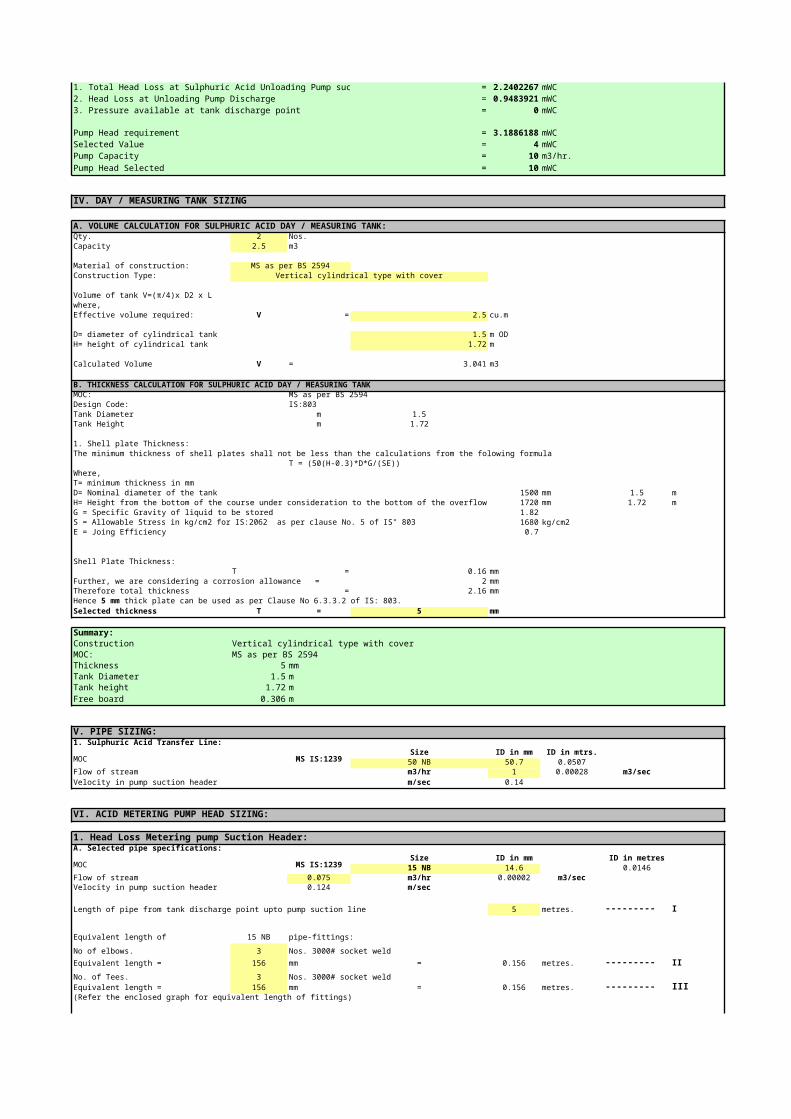
SUMMARY:Pump Head requirement shall be calculated as under:1. Total Head Loss at Sulphuric Acid Unloading Pump suction = 2.24022667 mWC2. Head Loss at Unloading Pump Discharge = 0.94839211 mWC3. Pressure available at tank discharge point = 0 mWC
Pump Head requirement = 3.18861878 mWCSelected Value = 4 mWCPump Capacity = 10 m3/hr.
Pump Head Selected = 10 mWC
IV. DAY / MEASURING TANK SIZING
A. VOLUME CALCULATION FOR SULPHURIC ACID DAY / MEASURING TANK:Qty. 2 Nos.Capacity 2.5 m3
Material of construction: MS as per BS 2594Construction Type: Vertical cylindrical type with cover
where,Effective volume required: V = 2.5 cu.m
D= diameter of cylindrical tank 1.5 m ODH= height of cylindrical tank 1.72 m
Calculated Volume V = 3.041 m3
B. THICKNESS CALCULATION FOR SULPHURIC ACID DAY / MEASURING TANKMOC: MS as per BS 2594Design Code: IS:803Tank Diameter m 1.5Tank Height m 1.72
1. Shell plate Thickness:The minimum thickness of shell plates shall not be less than the calculations from the folowing formula
T = (50(H-0.3)*D*G/(SE))Where,T= minimum thickness in mmD= Nominal diameter of the tank 1500 mm 1.5 mH= Height from the bottom of the course under consideration to the bottom of the overflow which limits tank filli 1720 mm 1.72 mG = Specific Gravity of liquid to be stored 1.82
1680 kg/cm2E = Joing Efficiency 0.7
Shell Plate Thickness:T = 0.16 mm
Further, we are considering a corrosion allowance = 2 mmTherefore total thickness = 2.16 mm
Selected thickness T = 5 mm
Summary:Construction Vertical cylindrical type with coverMOC: MS as per BS 2594Thickness 5 mmTank Diameter 1.5 mTank height 1.72 mFree board 0.306 m
Volume of tank V=(π/4)x D2 x L
S = Allowable Stress in kg/cm2 for IS:2062 as per clause No. 5 of IS" 803
Hence 5 mm thick plate can be used as per Clause No 6.3.3.2 of IS: 803.
V. PIPE SIZING:1. Sulphuric Acid Transfer Line:
MOC MS IS:1239Size ID in mm ID in mtrs.
50 NB 50.7 0.0507Flow of stream m3/hr 1 0.00028 m3/secVelocity in pump suction header m/sec 0.14
VI. ACID METERING PUMP HEAD SIZING:
1. Head Loss Metering pump Suction Header:A. Selected pipe specifications:
MOC MS IS:1239Size ID in mm ID in metres
15 NB 14.6 0.0146Flow of stream 0.075 m3/hr 0.00002 m3/secVelocity in pump suction header 0.124 m/sec
Length of pipe from tank discharge point upto pump suction line 5 metres. --------- I
Equivalent length of 15 NB pipe-fittings:
No of elbows. 3 Nos. 3000# socket weld
Equivalent length = 156 mm = 0.156 metres. --------- II
No. of Tees. 3 Nos. 3000# socket weldEquivalent length = 156 mm = 0.156 metres. --------- III(Refer the enclosed graph for equivalent length of fittings)
Total Equivalent length = I + II + III = 5.312 metres.selected length 6 metres.Constant C = 100
Head loss per meter length = 6.815(V/C)^1.852*(D)^(-1.167)
= 0.00394 mWC
Total head loss in pipeline = 0.02362 mWC --------- 1
B. Head loss through ball valve of 15 NBQty: 1 No.Flow through ball valve 0.075 m3//hr
Loss through ball valve 0.1 mWC --------- 2refer enclosed graph for ball valve
Head loss in metering pump suction header = 1+2= 0.123624655 mWC
Head Loss in Sulphuric Acid Metering Pump Suction Header 0.123624655 mWC --------- A
2. Head Loss in Metering Pump Suction Line:
MOC MS IS:1239Size ID in mm ID in metres
15 NB 14.6 0.0146Flow of stream 0.075 m3/hr 0.00002 m3/secVelocity in pump suction line 0.12439084594 m/sec
Length of pipe from pump suction header upto pump suction point 2 metres. --------- I
Equivalent length of 15 NB pipe-fittings:
No of elbows. 2 Nos. 3000# socket weld
Equivalent length = 104 mm = 0.104 metres. --------- II
No. of Tees. 2 Nos. 3000# socket weld
Equivalent length = 104 mm = 0.104 metres. --------- III(Refer the enclosed graph for equivalent length of fittings)
Total Equivalent length = I + II + III = 2.208 metres.selected length 3 metres.Constant C = 100
Head loss per meter length = 6.815(V/C)^1.852*(D)^(-1.167)
= 0.003937443 mWC
Total head loss in pipeline = 0.011812328 mWC --------- 1
B. Head loss through ball valve of 15 NBQty: 1 No.Flow through ball valve 0.075 m3//hr
Loss through ball valve 0.1 mWC --------- 2refer enclosed graph for ball valve
A. Selected pipe specifications:

= 2 mWC --------- 3
Head loss in metering pump suction line = 1+2+3= 2.111812328 mWC
Head Loss in Sulphuric Acid Metering Pump Suction Line 2.111812328 mWC --------- B
Total loss in Sulphuric Acid Metering Pump Suction line: A+B= 2.235436983 mWC
3. Head Loss in Metering Pump Discharge Line:A. Selected pipe specifications:
MOC MS IS:1239Size ID in mm ID in metres
15 NB 14.6 0.0146Flow of stream 0.075 m3/hr 0.00002 m3/secVelocity in pump suction header 0.124 m/sec
Length of pipe from tank discharge point upto pump discharge header 100 metres. --------- I
Equivalent length of 15 NB pipe-fittings:
No of elbows. 2 Nos. 3000# socket weld
Equivalent length = 104 mm = 0.104 metres. --------- II
No. of Tees. 2 Nos. 3000# socket weld
Equivalent length = 104 mm = 0.104 metres. --------- III(Refer the enclosed graph for equivalent length of fittings)
Total Equivalent length = I + II + III = 100.208 metres.selected length 101 metres.Constant C = 100
Head loss per meter length = 6.815(V/C)^1.852*(D)^(-1.167)
= 0.003937443 mWC
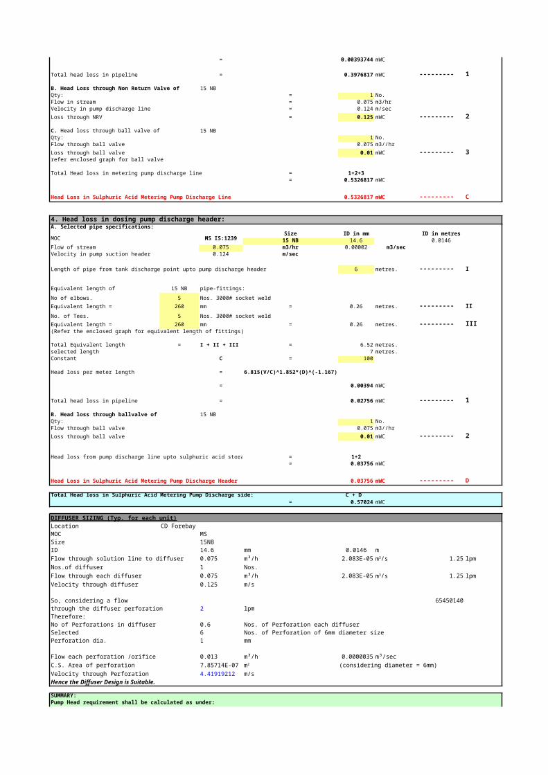
Total head loss in pipeline = 0.397681701 mWC --------- 1
B. Head Loss through Non Return Valve of 15 NBQty: = 1 No.Flow in stream = 0.075 m3/hrVelocity in pump discharge line = 0.124 m/sec
Loss through NRV = 0.125 mWC --------- 2
15 NBQty: 1 No.Flow through ball valve 0.075 m3//hr
Loss through ball valve 0.01 mWC --------- 3refer enclosed graph for ball valve
Total Head loss in metering pump discharge line = 1+2+3= 0.532681701 mWC
Head Loss in Sulphuric Acid Metering Pump Discharge Line 0.532681701 mWC --------- C
4. Head loss in dosing pump discharge header:A. Selected pipe specifications:
MOC MS IS:1239Size ID in mm ID in metres
15 NB 14.6 0.0146Flow of stream 0.075 m3/hr 0.00002 m3/secVelocity in pump suction header 0.124 m/sec
Length of pipe from tank discharge point upto pump discharge header 6 metres. --------- I
Equivalent length of 15 NB pipe-fittings:
No of elbows. 5 Nos. 3000# socket weld
Equivalent length = 260 mm = 0.26 metres. --------- II
No. of Tees. 5 Nos. 3000# socket weld
Equivalent length = 260 mm = 0.26 metres. --------- III(Refer the enclosed graph for equivalent length of fittings)
Total Equivalent length = I + II + III = 6.52 metres.selected length 7 metres.Constant C = 100
Head loss per meter length = 6.815(V/C)^1.852*(D)^(-1.167)
= 0.00394 mWC
Total head loss in pipeline = 0.02756 mWC --------- 1
C. Head loss through Y-type strainer
C. Head loss through ball valve of
B. Head loss through ballvalve of 15 NBQty: 1 No.Flow through ball valve 0.075 m3//hr
Loss through ball valve 0.01 mWC --------- 2
Head loss from pump discharge line upto sulphuric acid storage tank inlet p = 1+2= 0.03756 mWC
Head Loss in Sulphuric Acid Metering Pump Discharge Header 0.03756 mWC --------- D
Total Head loss in Sulphuric Acid Metering Pump Discharge side: C + D= 0.57024 mWC
DIFFUSER SIZING (Typ. for each unit)Location CD Forebay MOC MSSize 15NBID 14.6 mm 0.0146 mFlow through solution line to diffuser 0.075 m³/h 2.08333E-05 1.25 lpmNos.of diffuser 1 Nos.Flow through each diffuser 0.075 m³/h 2.08333E-05 1.25 lpmVelocity through diffuser 0.125 m/s
So, considering a flow 65450140through the diffuser perforation 2 lpmTherefore:No of Perforations in diffuser 0.6 Nos. of Perforation each diffuserSelected 6 Nos. of Perforation of 6mm diameter sizePerforation dia. 1 mm
Flow each perforation /orifice 0.012 m³/h 0.0000035 m³/secC.S. Area of perforation 7.8571425E-07 (considering diameter = 6mm) Velocity through Perforation 4.41919212006 m/sHence the Diffuser Design is Suitable.
SUMMARY:Pump Head requirement shall be calculated as under: 1. Total Head Loss in Sulphuric Acid Metering Pump suction = 2.235436983 mWC2. Head Loss in sulphuric Acid Metering Pump Discharge = 0.570243799 mWC
3. Pressure available at tank discharge point = 0 mWC
Pump Head requirement = 2.805680782 mWC
Selected Value = 3 mWCPump Capacity = 75 LPHPump Head Selected = 10 mWC
m3/s
m3/s
m2

ProjectOwnerContractorConsultantSystemSystem supplierDocumentDocument No.
I. STORAGE TANK SIZING:
A. VOLUME CALCULATION FOR INHIBITOR TANKS:Qty. 1 Nos.Capacity 1 m3
Material of construction: MSRL as per IS 2062Construction Type: Vertical cylindrical type with cover
where,Effective volume required: V = 1 m3
D= diameter of cylindrical tank 1.1 m ODH= height of cylindrical tank 1.225 m
Calculated Volume V = 1.165 m3
B. THICKNESS CALCULATION FOR INHIBITOR STORAGE TANKSMOC: MSRL as per IS 2062Design Code: IS:803Tank Diameter m 1.1Tank Height m 1.225
1. Shell plate Thickness:The minimum thickness of shell plates shall not be less than the calculations from the folowing formula
T = (50(H-0.3)*D*G/(SE))Where,T= minimum thickness in mmD= Nominal diameter of the tank 1100 mm 1.1 mH= Height from the bottom of the course under consideration to the bottom of the overflow which l 1225 mm 1.225 mG = Specific Gravity of liquid to be stored 1.1 Corrosion I 1.25 Scale Inhibitor
1680 kg/cm2E = Joing Efficiency 0.7
Shell Plate Thickness:T = 0.05 mm
Further, we are considering a corrosion allowance = 2 mmTherefore total thickness = 2.05 mm
Selected thickness T = 5 mm
Summary:Construction: Vertical cylindrical type with coverMOC: MSRL as per IS 2062Thickness: 5 mmTank Diameter: 1.1 mTank height: 1.225 mFree board: 0.173 m
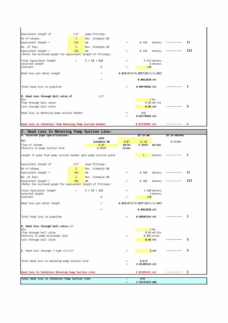
II. METERING PUMP HEAD SIZING:
1. Head Loss In Metering pump Suction Header:A. Selected pipe specifications: Size ID in mm ID in metres
Volume of tank V=(π/4)x D2 x L
S = Allowable Stress in kg/cm2 for IS:2062 as per clause No. 5 of IS" 803
Hence 5 mm thick plate can be used as per Clause No 6.3.3.2 of IS: 803.
MOC 1/2" 13.86 0.01386
Flow of stream 0.05 m3/hr 0.00001 m3/secVelocity in pump suction header 0.0920 m/sec
Length of pipe from tank discharge point upto pump suction line 5 metres. --------- I
Equivalent length of 1/2" pipe-fittings:
No of elbows. 3 Nos. Schedule 80
Equivalent length = 156 mm = 0.156 metres. --------- II
No. of Tees. 3 Nos. Schedule 80
Equivalent length = 156 mm = 0.156 metres. --------- III(Refer the enclosed graph for equivalent length of fittings)
Total Equivalent length = I + II + III = 5.312 metres.selected length 6 metres.Constant C = 140
Head loss per meter length = 6.815(V/C)^1.852*(D)^(-1.167)
= 0.0012838 mWC
Total head loss in pipeline = 0.00770281 mWC --------- 1
B. Head loss through Ball valve of 1/2"Qty: 1 No.Flow through ball valve 0.05 m3//hr
Loss through ball valve 0.01 mWC --------- 2
Head loss in metering pump suction header = 1+2= 0.01770281 mWC
Head loss in Inhibitor Tank Metering Pump Suction Header: 0.01770281 mWC --------- A
2. Head Loss In Metering Pump Suction Line:A. Selected pipe specifications: ID in mm ID in metres
MOC 1/2" 13.86 0.01386Flow of stream 0.05 m3/hr 0.00001 m3/secVelocity in pump suction line 0.0920 m/sec
Length of pipe from pump suction header upto pump suction point 2 metres. --------- I
Equivalent length of 1/2" pipe-fittings:
No of elbows. 2 Nos. Schedule 80
Equivalent length = 104 mm = 0.104 metres. --------- II
No. of Tees. 2 Nos. Schedule 80
Equivalent length = 104 mm = 0.104 metres. --------- III(Refer the enclosed graph for equivalent length of fittings)
Total Equivalent length = I + II + III = 2.208 metres.selected length 3 metres.Constant C = 140
Head loss per meter length = 6.815(V/C)^1.852*(D)^(-1.167)
= 0.0012838 mWC
Total head loss in pipeline = 0.00385141 mWC --------- 1
B. Head loss through ball valve of 1/2"Qty: 1 No.Flow through ball valve 0.05 m3//hrVelocity in pump discharge line = 0.092 m/sec
Loss through ball valve 0.01 mWC --------- 2
1/2" = 2 mWC --------- 3
uPVCSchedule 80
uPVCSchedule 80
C. Head loss through Y-type strainer

Total Head loss in metering pump suction line = 1+2+3= 2.01385141 mWC
Head loss in Inhibitor Metering Pump Suction Line: 2.01385141 mWC --------- B
Total head loss in Inhibitor Pump Suction line: = A+B= 2.03155422 mWC
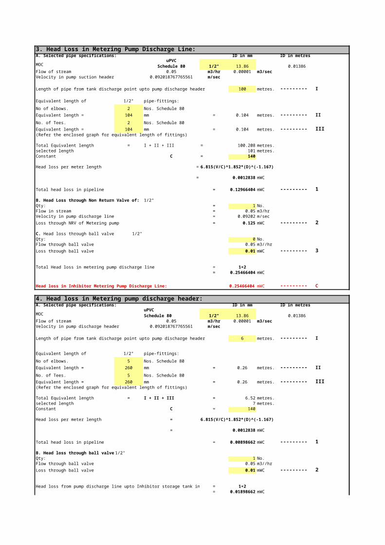
3. Head Loss in Metering Pump Discharge Line:A. Selected pipe specifications: ID in mm ID in metres
MOC 1/2" 13.86 0.01386Flow of stream 0.05 m3/hr 0.00001 m3/secVelocity in pump suction header 0.092018767765561 m/sec
Length of pipe from tank discharge point upto pump discharge header 100 metres. --------- I
Equivalent length of 1/2" pipe-fittings:
No of elbows. 2 Nos. Schedule 80
Equivalent length = 104 mm = 0.104 metres. --------- II
No. of Tees. 2 Nos. Schedule 80
Equivalent length = 104 mm = 0.104 metres. --------- III(Refer the enclosed graph for equivalent length of fittings)
Total Equivalent length = I + II + III = 100.208 metres.selected length 101 metres.Constant C = 140
Head loss per meter length = 6.815(V/C)^1.852*(D)^(-1.167)
= 0.0012838 mWC
Total head loss in pipeline = 0.12966404 mWC --------- 1
B. Head Loss through Non Return Valve of: 1/2"Qty: = 1 No.Flow in stream = 0.05 m3/hrVelocity in pump discharge line = 0.09202 m/sec
Loss through NRV of Metering pump = 0.125 mWC --------- 2
1/2"Qty: 0 No.Flow through ball valve 0.05 m3//hr
Loss through ball valve 0.01 mWC --------- 3
Total Head loss in metering pump discharge line = 1+2= 0.25466404 mWC
Head loss in Inhibitor Metering Pump Discharge Line: 0.25466404 mWC --------- C
4. Head loss in Metering pump discharge header:A. Selected pipe specifications: ID in mm ID in metres
MOC 1/2" 13.86 0.01386Flow of stream 0.05 m3/hr 0.00001 m3/secVelocity in pump discharge header 0.092018767765561 m/sec
Length of pipe from tank discharge point upto pump discharge header 6 metres. --------- I
Equivalent length of 1/2" pipe-fittings:
No of elbows. 5 Nos. Schedule 80
Equivalent length = 260 mm = 0.26 metres. --------- II
No. of Tees. 5 Nos. Schedule 80
Equivalent length = 260 mm = 0.26 metres. --------- III(Refer the enclosed graph for equivalent length of fittings)
uPVCSchedule 80
C. Head loss through ball valve of :
uPVCSchedule 80

Total Equivalent length = I + II + III = 6.52 metres.selected length 7 metres.Constant C = 140
Head loss per meter length = 6.815(V/C)^1.852*(D)^(-1.167)
= 0.0012838 mWC
Total head loss in pipeline = 0.00898662 mWC --------- 1
B. Head loss through ball valve of : 1/2"Qty: 1 No.Flow through ball valve 0.05 m3//hr
Loss through ball valve 0.01 mWC --------- 2
Head loss from pump discharge line upto Inhibitor storage tank inlet point = 1+2= 0.01898662 mWC
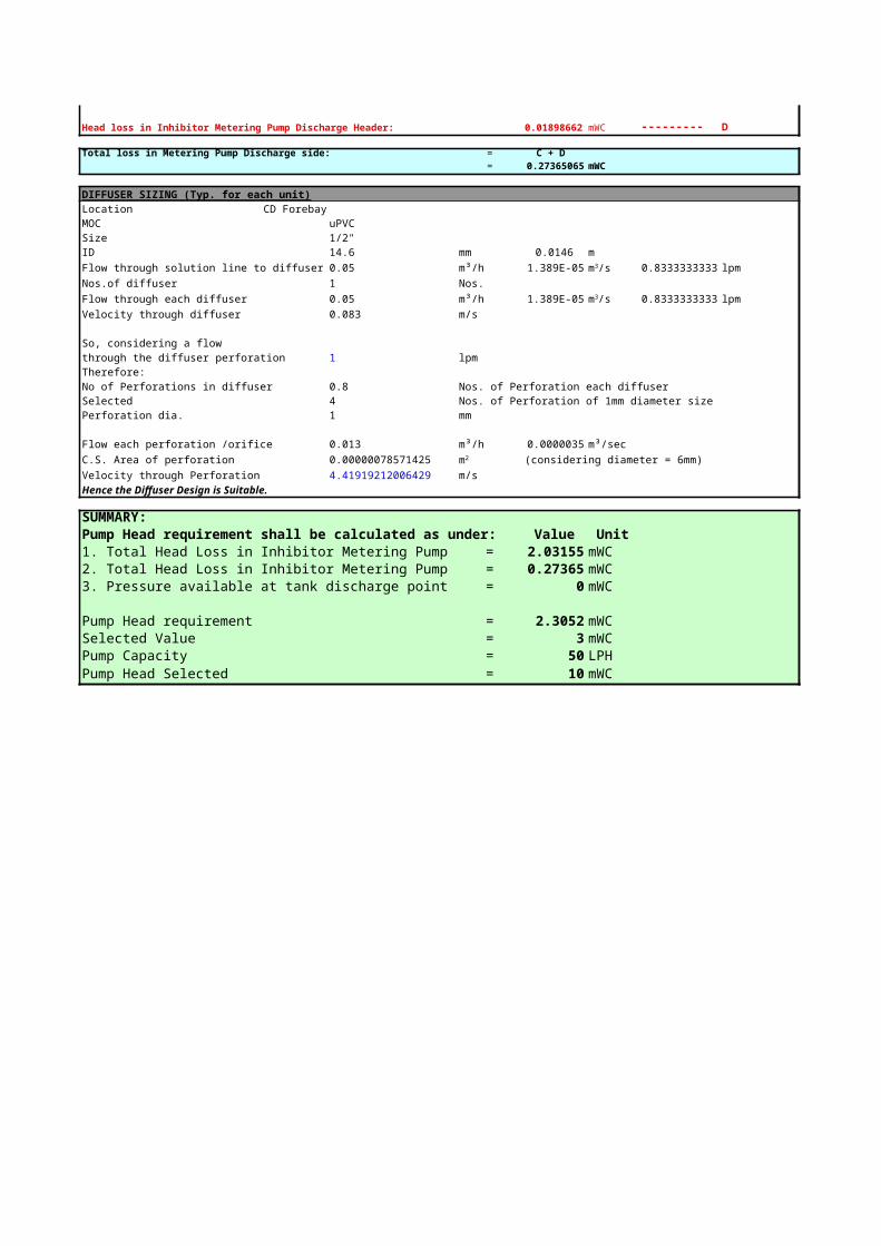
Head loss in Inhibitor Metering Pump Discharge Header: 0.01898662 mWC --------- D
Total loss in Metering Pump Discharge side: = C + D= 0.27365065 mWC
DIFFUSER SIZING (Typ. for each unit)Location CD Forebay MOC uPVCSize 1/2"ID 14.6 mm 0.0146 mFlow through solution line to diffuser 0.05 m³/h 1.38889E-05 0.83333333333 lpmNos.of diffuser 1 Nos.Flow through each diffuser 0.05 m³/h 1.38889E-05 0.83333333333 lpmVelocity through diffuser 0.083 m/s
So, considering a flowthrough the diffuser perforation 1 lpmTherefore:No of Perforations in diffuser 0.8 Nos. of Perforation each diffuserSelected 4 Nos. of Perforation of 1mm diameter sizePerforation dia. 1 mm
Flow each perforation /orifice 0.013 m³/h 0.0000035 m³/secC.S. Area of perforation 0.00000078571425 (considering diameter = 6mm) Velocity through Perforation 4.41919212006429 m/sHence the Diffuser Design is Suitable.
SUMMARY:Pump Head requirement shall be calculated as under: Value Unit1. Total Head Loss in Inhibitor Metering Pump suction = 2.03155 mWC2. Total Head Loss in Inhibitor Metering Pump Discharge = 0.27365 mWC3. Pressure available at tank discharge point = 0 mWC
Pump Head requirement = 2.3052 mWCSelected Value = 3 mWCPump Capacity = 50 LPHPump Head Selected = 10 mWC
m3/s
m3/s
m2
ProjectOwnerContractorConsultantSystemSystem supplierDocumentDocument No.
Ref Drwg / Doc.
Annexure-3 Questionnaire
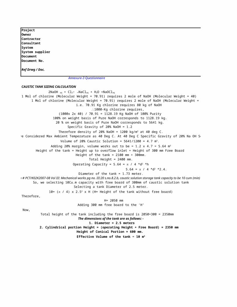
CAUSTIC TANK SIZING CALCULATION
1 Mol of chlorine (Molecular Weight = 70.91) requires 2 mole of NaOH (Molecular Weight = 40)1 Mol of chlorine (Molecular Weight = 70.91) requires 2 mole of NaOH (Molecular Weight = 40)
i.e. 70.91 Kg chlorine requires 80 kg of NaOH
(1000x 2x 40) / 70.91 = 1128.19 Kg NaOH of 100% Purity 100% on weight basis of Pure NaOH corresponds to 1128.19 kg.
20 % on weight basis of Pure NaOH corresponds to 5641 kg. Specific Gravity of 20% NaOH = 1.2
Height of the tank = Height up to overflow inlet + Height of 300 mm Free Board Height of the tank = 2100 mm + 300mm.
Total Height = 2400 mm.
Diameter of the tank = 1.73 meter.(As per Tender specification # PCT/K02K2007-08 Vol III: Mechanical works pg no. III:20 s.no.8.2.b, caustic solution storage tank capacity to be 10 cum (min) with free board of 300mm)
So, we selecting 10Cu.m capacity with free board of 300mm of caustic solution tankSelecting a tank Diameter of 2.5 meter.
Therefore, H= 2050 mm
Adding 300 mm free board to the ‘H’
Total height of the tank including the free board is 2050+300 = 2350mmThe dimensions of the tank are as follows: -
1. Diameter = 2.5 meters 2. Cylindrical portion Height = (operating Height + Free Board) = 2350 mm
Height of Conical Portion = 600 mm.
2NaOH aq + Cl2↑ →NaClaq + H2O +NaOClaq
\1000-Kg chlorine requires,
Therefore density of 20% NaOH = 1200 kg/m3 at 40 deg C.(Note: We have Considered Max Ambient Temperature as 40 Deg C. At 40 Deg C Specific Gravity of 20% Na OH Solution =1.2
Volume of 20% Caustic Solution = 5641/1200 = 4.7 m3.
Adding 20% margin, volume works out to be = 1.2 x 4.7 = 5.64 m3
Operating Capacity = 5.64 = p / 4 *d2 *h
5.64 = p / 4 *d2 *2.4.
10= (p / 4) x 2.52 x H (H= Height of the tank without free board)
Now,
Effective Volume of the tank = 10 m3
ProjectOwnerContractorConsultantSystemSystem supplierDocumentDocument No.
Ref Drwg / Doc. 1
I. STORAGE TANK SIZING:
A. VOLUME CALCULATION FOR HYPOCHLORITE DOSING TANK:Qty. 1 Nos.Capacity 0.1 m3
Material of construction: PP+FRPConstruction Type: Vertical cylindrical type with flat bottom and cover
where, Hypo sol. Preparation tankEffective volume required: V = 0.1 m3 0.2 m3
D= diameter of cylindrical tank = 0.5 m OD 0.6 m ODH= height of cylindrical tank = 0.7 m OD 0.8 m ODT= Thickness of Tank = = 5 mm mmCalculated Volume V = 0.137 m3 0.226 m3
Summary:Construction: Vertical cylindrical type with flat bottom and coverMOC: PP+FRPThickness: 0 mmTank Diameter: 0.5 mTank height: 0.7 mFree board: 0.191 m
METERING PUMP HEAD SIZING:
1. Head Loss in Metering Pump Discharge Line:A. Selected pipe specifications: Size ID in mm ID in metres
MOC 1/2" 13.86 0.01386Flow of stream 0.005 m3/hr 0.0000014 m3/secVelocity in Pump Discharge line 0.0092 m/sec
Length of from pump discharge to dosing point: 50 metres. --------- I
Equivalent length of 1/2" pipe-fittings:
No of elbows. 12 Nos. Schedule 80
Equivalent length = 624 mm = 0.624 metres. --------- II
No. of Tees. 0 Nos. Schedule 80
Equivalent length = 0 mm = 0 metres. --------- III
Total Equivalent length = I + II + III = 50.624 metres.selected length 51 metres.Constant C = 140
Head loss per meter length = 6.815(V/C)^1.852*(D)^(-1.167)
= 1.80508711E-05 mWC
Total head loss in pipeline = 0.00092059443 mWC --------- 1
Head loss in Inhibitor Tank Metering Pump Delivery line: 0.000921 mWC --------- A
Volume of tank V=(π/4)x D2 x L
uPVCSchedule 80
METERING PUMP SELECTION:
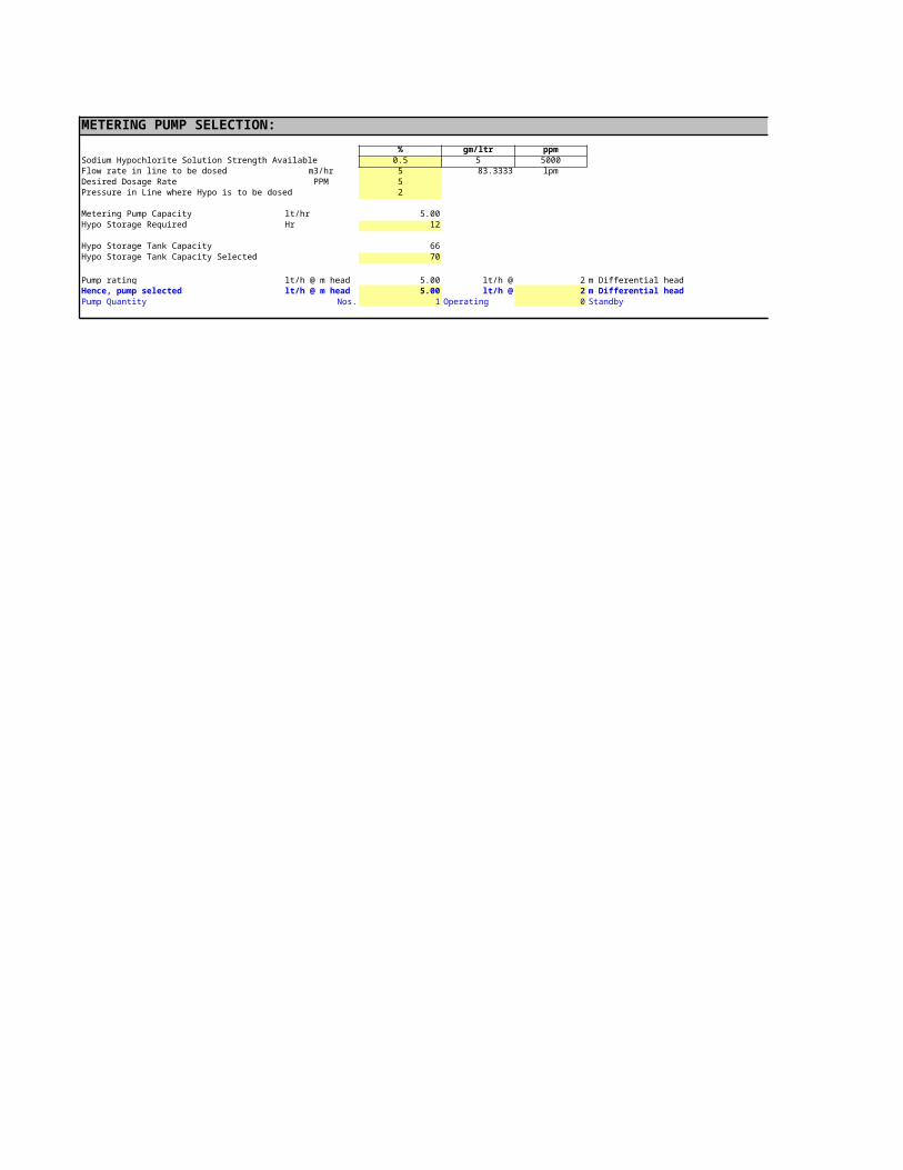
% gm/ltr ppmSodium Hypochlorite Solution Strength Available 0.5 5 5000Flow rate in line to be dosed m3/hr 5 83.3333 lpmDesired Dosage Rate PPM 5Pressure in Line where Hypo is to be dosed 2
Metering Pump Capacity lt/hr 5.00Hypo Storage Required Hr 12
Hypo Storage Tank Capacity 66Hypo Storage Tank Capacity Selected 70
Pump rating lt/h @ m head 5.00 lt/h @ 2 m Differential headHence, pump selected lt/h @ m head 5.00 lt/h @ 2 m Differential headPump Quantity Nos. 1 Operating 0 Standby
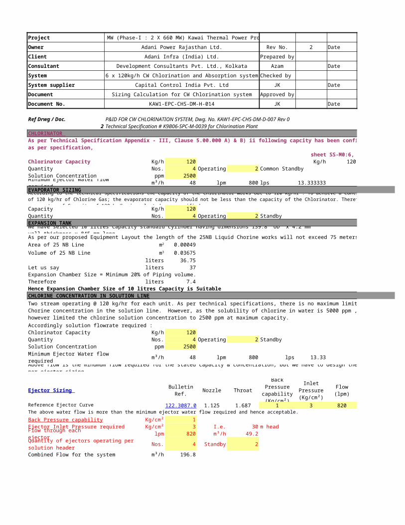
Project 1320 MW (Phase-I : 2 X 660 MW) Kawai Thermal Power Project
Owner Adani Power Rajasthan Ltd. Rev No. 2 Date 25.04.2011
Client Adani Infra (India) Ltd. Prepared by
Consultant Development Consultants Pvt. Ltd., Kolkata Azam Date 25.04.2011
System 6 x 120kg/h CW Chlorination and Absorption system Checked by
System supplier Capital Control India Pvt. Ltd JK Date 25.04.2011
Document Sizing Calculation for CW Chlorination system Approved by
Document No. KAW1-EPC-CHS-DM-H-014 JK Date 25.04.2011
Ref Drwg / Doc. 12 Technical Specification # K9B06-SPC-M-0039 for Chlorination Plant
CHLORINATOR As per Technical Specification Appendix - III, Clause 5.00.000 A) & B) ii following capcity has been confirmed:
Kg/h 120 Kg/h 120 Rated capacity
Quantity Nos. 4 Operating 2 Common Standby Solution Concentration ppm 2500Minimum Ejector Water flow required m³/h 48 lpm 800 lps 13.3333333EVAPORATOR SIZING
Capacity Kg/h 120Quantity Nos. 4 Operating 2 StandbyEXPANSION TANKWe have selected 10 litres Capacity standard cylinder having dimensions 139.8 ’OD’ x 4.2 mm wall thickness x 845 mm long.As per our proposed Equipment Layout the length of the 25NB Liquid Chorine works will not exceed 75 meters.Area of 25 NB Line 0.00049
Volume of 25 NB Line 0.03675liters 36.75
Let us say liters 37Expansion Chamber Size = Minimum 20% of Piping volume.Therefore liters 7.4Hence Expansion Chamber Size of 10 litres Capacity is SuitableCHLORINE CONCENTRATION IN SOLUTION LINE
Accordingly solution flowrate required :Chlorinator Capacity Kg/h 120Quantity Nos. 4 Operating 2 StandbySolution Concentration ppm 2500
Minimum Ejector Water flow required m³/h 48 lpm 800 lps 13.33
Above flow is the minumum flow required for the stated capacity & concentration, but we have to design the system as per ejector sizing
Ejector Sizing Bulletin Ref. Nozzle Throat Flow (lpm) Flow m³/h
Reference Ejector Curve 122.3087.0 1.125 1.687 1 3 820 49.2The above water flow is more than the minimum ejector water flow required and hence acceptable.
Kg/cm² 1Ejector Inlet Pressure required Kg/cm² 3 I.e. 30 m headFlow through each ejector lpm 820 m³/h 49.2
Nos. 4 Standby 2
Combined Flow for the system m³/h 196.8
P&ID FOR CW CHLORINATION SYSTEM, Dwg. No. KAW1-EPC-CHS-DM-D-007 Rev 0
6 x 120Kg/h capacity streams have been provided; 2working for unit-1, 2working for unit-2 and 2Nos. common stand by as per specification, sheet SS-M0:6, clause 4.00.00A
Chlorinator Capacity
According to the technical specifications the capacity of the Chlorinator works out to 120 kg/hr . To achieve a continuous flow of 120 kg/hr of Chlorine Gas; the evaporator capacity should not be less than the capacity of the Chlorinator. Therefore an evaporator of Capacity of 120 kg/hr is selected, as specified.
m2
m3
Two stream operating @ 120 kg/hr for each unit. As per technical specifications, there is no maximum limit on the Chorine concentration in the solution line. However, as the solubility of chlorine in water is 5000 ppm , we have however limited the chlorine solution concentration to 2500 ppm at maximum capacity.
Back Pressure capability (Kg/cm²)
Inlet Pressure (Kg/cm²)
Back Pressure capability
Quantity of ejectors operating per solution header

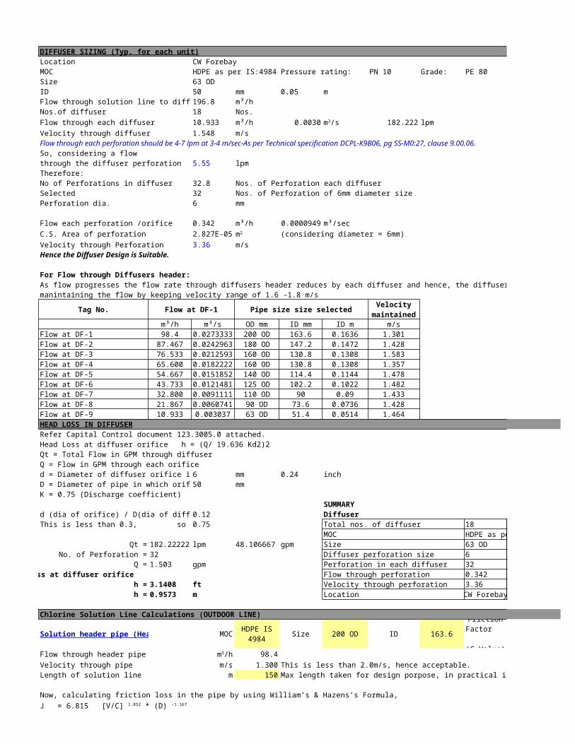
DIFFUSER SIZING (Typ. for each unit)Location CW Forebay MOC HDPE as per IS:4984 Pressure rating: PN 10 Grade: PE 80Size 63 ODID 50 mm 0.05 mFlow through solution line to diffuser 196.8 m³/hNos.of diffuser 18 Nos.Flow through each diffuser 10.933 m³/h 0.0030 182.222 lpmVelocity through diffuser 1.548 m/sFlow through each perforation should be 4-7 lpm at 3-4 m/sec-As per Technical specification DCPL-K9B06, pg SS-M0:27, clause 9.00.06.So, considering a flowthrough the diffuser perforation 5.55 lpmTherefore:No of Perforations in diffuser 32.8 Nos. of Perforation each diffuserSelected 32 Nos. of Perforation of 6mm diameter sizePerforation dia. 6 mm
Flow each perforation /orifice 0.342 m³/h 0.0000949 m³/secC.S. Area of perforation 0.00002827 (considering diameter = 6mm) Velocity through Perforation 3.36 m/sHence the Diffuser Design is Suitable.
For Flow through Diffusers header:As flow progresses the flow rate through diffusers header reduces by each diffuser and hence, the diffuser header size reduced progressively manintaining the flow by keeping velocity range of 1.6 -1.8 m/s
Tag No. Flow at DF-1 Pipe size size selected
m³/h m³/s OD mm ID mm ID m m/sFlow at DF-1 98.4 0.02733333 200 OD 163.6 0.1636 1.301Flow at DF-2 87.467 0.0242963 180 OD 147.2 0.1472 1.428Flow at DF-3 76.533 0.02125926 160 OD 130.8 0.1308 1.583Flow at DF-4 65.600 0.01822222 160 OD 130.8 0.1308 1.357Flow at DF-5 54.667 0.01518519 140 OD 114.4 0.1144 1.478Flow at DF-6 43.733 0.01214815 125 OD 102.2 0.1022 1.482Flow at DF-7 32.800 0.00911111 110 OD 90 0.09 1.433Flow at DF-8 21.867 0.00607407 90 OD 73.6 0.0736 1.428Flow at DF-9 10.933 0.00303704 63 OD 51.4 0.0514 1.464HEAD LOSS IN DIFFUSERRefer Capital Control document 123.3005.0 attached.Head Loss at diffuser orifice h = (Q/ 19.636 Kd2)2 Qt = Total Flow in GPM through diffuserQ = Flow in GPM through each orificed = Diameter of diffuser orifice in inches = 6 mm 0.24 inchD = Diameter of pipe in which orifice is placed 50 mmK = 0.75 (Discharge coefficient)
SUMMARYd (dia of orifice) / D(dia of diffuser) = 0.12 DiffuserThis is less than 0.3, so k = 0.75 Total nos. of diffuser 18 Nos.
MOC HDPE as per PN 10Qt = 182.222222 lpm 48.1066667 gpm Size 63 OD
No. of Perforation = 32 Diffuser perforation size 6 mmQ = 1.503 gpm Perforation in each diffuser 32 Nos.
Head Loss at diffuser orifice Flow through perforation 0.342 m³/h h = 3.1408 ft Velocity through perforation 3.36 m/s h = 0.9573 m Location CW Forebay
Chlorine Solution Line Calculations (OUTDOOR LINE)
MOC Size 200 OD ID 163.6 140
Flow through header pipe 98.4Velocity through pipe m/s 1.300 This is less than 2.0m/s, hence acceptable.Length of solution line m 150 Max length taken for design porpose, in practical it will be less.
Now, calculating friction loss in the pipe by using William’s & Hazens’s Formula,
m3/s
m2
Velocity maintained
Solution header pipe (Header of two nos. of ejector) HDPE IS 4984
Friction Factor (C Value)
m3/h
J = 6.815 [V/C] 1.852 * (D) -1.167

Where,J = Head loss in mtr/mtr length of pipe
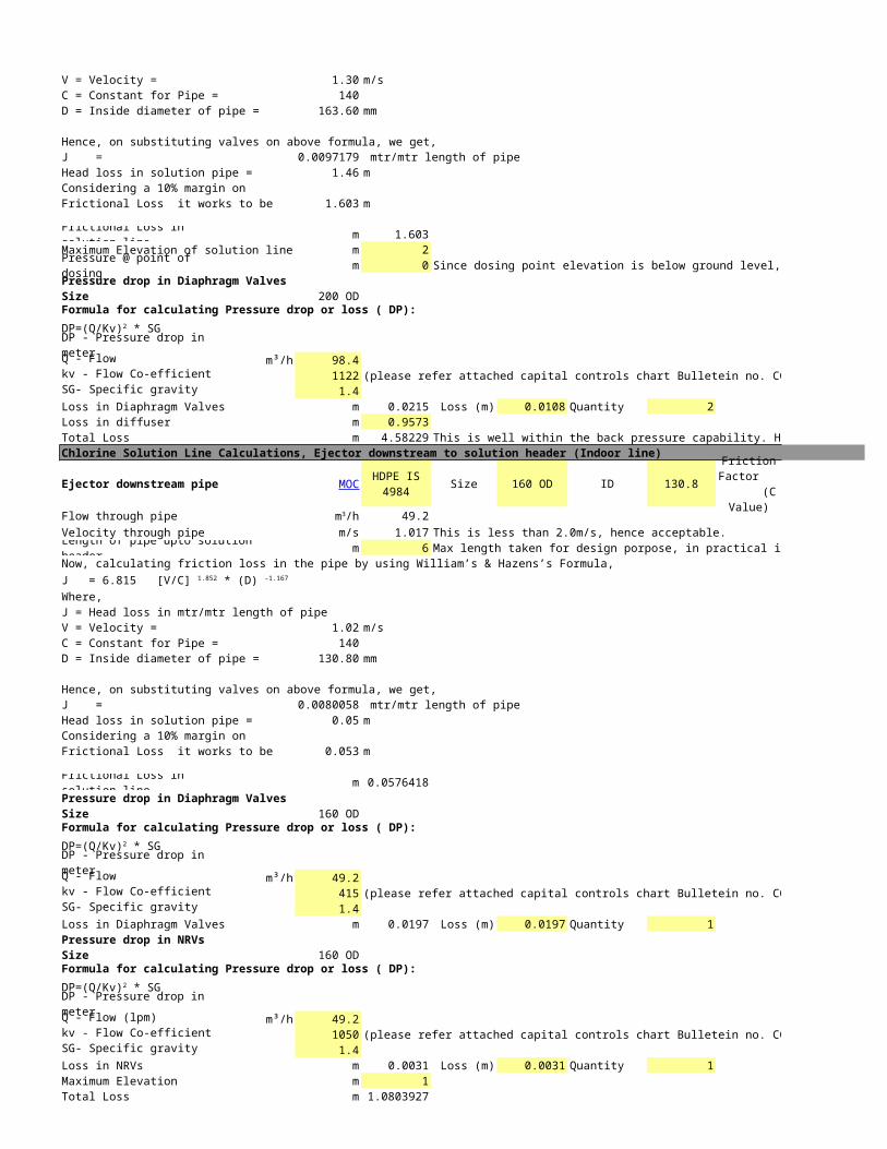
V = Velocity = 1.30 m/sC = Constant for Pipe = 140D = Inside diameter of pipe = 163.60 mm
Hence, on substituting valves on above formula, we get,J = 0.0097179 mtr/mtr length of pipeHead loss in solution pipe = 1.46 mConsidering a 10% margin on Frictional Loss it works to be 1.603 m
Frictional Loss in solution line m 1.603Maximum Elevation of solution line m 2Pressure @ point of dosing m 0 Since dosing point elevation is below ground level, it is not considered.Pressure drop in Diaphragm ValvesSize 200 ODFormula for calculating Pressure drop or loss ( DP):
DP - Pressure drop in meterQ - Flow m³/h 98.4kv - Flow Co-efficient 1122 (please refer attached capital controls chart Bulletein no. CCIPL-KV-DV/BFV/NRV-001)SG- Specific gravity 1.4Loss in Diaphragm Valves m 0.0215 Loss (m) 0.0108 Quantity 2Loss in diffuser m 0.9573Total Loss m 4.58228998 This is well within the back pressure capability. Hence, O.K.Chlorine Solution Line Calculations, Ejector downstream to solution header (Indoor line)
Ejector downstream pipe Size 160 OD ID 130.8 140
Flow through pipe 49.2Velocity through pipe m/s 1.017 This is less than 2.0m/s, hence acceptable.Length of pipe upto solution header m 6 Max length taken for design porpose, in practical it will be less.Now, calculating friction loss in the pipe by using William’s & Hazens’s Formula,
Where,J = Head loss in mtr/mtr length of pipe V = Velocity = 1.02 m/sC = Constant for Pipe = 140D = Inside diameter of pipe = 130.80 mm
Hence, on substituting valves on above formula, we get,J = 0.0080058 mtr/mtr length of pipeHead loss in solution pipe = 0.05 mConsidering a 10% margin on Frictional Loss it works to be 0.053 m
Frictional Loss in solution line m 0.05764177Pressure drop in Diaphragm ValvesSize 160 ODFormula for calculating Pressure drop or loss ( DP):
DP - Pressure drop in meterQ - Flow m³/h 49.2kv - Flow Co-efficient 415 (please refer attached capital controls chart Bulletein no. CCIPL-KV-DV/BFV/NRV-001)SG- Specific gravity 1.4Loss in Diaphragm Valves m 0.0197 Loss (m) 0.0197 Quantity 1Pressure drop in NRVsSize 160 ODFormula for calculating Pressure drop or loss ( DP):
DP - Pressure drop in meterQ - Flow (lpm) m³/h 49.2kv - Flow Co-efficient 1050 (please refer attached capital controls chart Bulletein no. CCIPL-KV-DV/BFV/NRV-001)SG- Specific gravity 1.4Loss in NRVs m 0.0031 Loss (m) 0.0031 Quantity 1Maximum Elevation m 1Total Loss m 1.08039274
DP=(Q/Kv)2 * SG
MOC HDPE IS 4984
Friction Factor
(C Value)
m3/h
J = 6.815 [V/C] 1.852 * (D) -1.167
DP=(Q/Kv)2 * SG
DP=(Q/Kv)2 * SG

Back Pressure on Ejector m 5.66268272 This is within the permissible back pressure of 10m or 1kg/cm2. Hence, O.K.

Motive Water Line Calculations, Pump Discharge header upto Ejector upstream
CS IS 3589 Size 219.1 OD ID 208 100
Flow through pipe 196.8Velocity through pipe m/s 1.609 Velocity limit range (1.5-2.4m/s).This is less than 2.4m/s, hence acceptable.
m 12 Max length taken for design porpose, in practical it will be less.
Now, calculating friction loss in the pipe by using William’s & Hazens’s Formula,
Where,J = Head loss in mtr/mtr length of pipe V = Velocity = 1.61 m/sC = Constant for Pipe = 100D = Inside diameter of pipe = 208.00 mm
Hence, on substituting valves on above formula, we get,J = 0.0203123 mtr/mtr length of pipeHead loss in solution pipe = 0.24 mConsidering a 10% margin on Frictional Loss it works to be 0.268 mFrictional Loss m 0.268Pressure drop in butterfly ValvesSize 219.1 ODFormula for calculating Pressure drop or loss ( DP):
DP - Pressure drop in meterQ - Flow m³/h 196.8kv - Flow Co-efficient 1122 (please refer attached capital controls chart Bulletein no. CCIPL-KV-DV/BFV/NRV-001)SG- Specific gravity 1Loss in butterfly valve m 0.062 Loss (m) 0.031 Quantity 2Loss in Flowmeter m 5Maximum Elevation m 2Total Loss m 7.330 A
Motive Water Line Calculations, Pump Discharge line upto Discharge header
Booster Pump Discharge line CS IS 1239 Size 150 NB ID 153.1 100
Flow through pipe 98.4Velocity through pipe m/s 1.485 Velocity limit range (3m/s). This is less than 3m/s, hence acceptable.
m 12 Max length taken for design porpose, in practical it will be less.
Now, calculating friction loss in the pipe by using William’s & Hazens’s Formula,
Where,J = Head loss in mtr/mtr length of pipe V = Velocity = 1.48 m/sC = Constant for Pipe = 100D = Inside diameter of pipe = 153.10 mm
Hence, on substituting valves on above formula, we get,J = 0.0250336 mtr/mtr length of pipeHead loss in solution pipe = 0.30 mConsidering a 10% margin on Frictional Loss it works to be 0.330 mFrictional Loss m 0.330Pressure drop in butterfly ValvesSize 150 NBFormula for calculating Pressure drop or loss ( DP):
DP - Pressure drop in meterQ - Flow m³/h 98.4kv - Flow Co-efficient 880 (please refer attached capital controls chart Bulletein no. CCIPL-KV-DV/BFV/NRV-001)
Booster Pump Discharge Header line MOC
Friction Factor (C Value)
m3/h
Length of pipe, from pump discharge header upto ejector
J = 6.815 [V/C] 1.852 * (D) -1.167
DP=(Q/Kv)2 * SG
MOCFriction
Factor (C Value)
m3/h
Length of pipe, from pump discharge header upto ejector
J = 6.815 [V/C] 1.852 * (D) -1.167
DP=(Q/Kv)2 * SG
SG- Specific gravity 1
Loss in butterfly valve m 0.013 Loss (m) 0.013 Quantity 1Pressure drop in NRVsSize 150 NBFormula for calculating Pressure drop or loss ( DP):
DP - Pressure drop in meterQ - Flow (lpm) m³/h 98.4kv - Flow Co-efficient 1050 (please refer attached capital controls chart Bulletein no. CCIPL-KV-DV/BFV/NRV-001)SG- Specific gravity 1Loss in NRVs m 0.00878 Loss (m) 0.0088 Quantity 1Total Loss m 0.352 B
Pressure required @ pump discharge 37.7 Ejector Inlet pressure + A + B
Motive Water Line Calculations, motive water header
Booster pump suction line CS IS 3589 Size 150 NB ID 153.1 100
Flow through pipe 98.4Velocity through pipe m/s 1.485 Velocity limit range (1.5m/s). This is less than 1.5m/s, hence acceptable.
m 6 Max length taken for design porpose, in practical it will be less.
Now, calculating friction loss in the pipe by using William’s & Hazens’s Formula,
Where,J = Head loss in mtr/mtr length of pipe V = Velocity = 1.48 m/sC = Constant for Pipe = 100D = Inside diameter of pipe = 153.10 mm
Hence, on substituting valves on above formula, we get,J = 0.0250336 mtr/mtr length of pipeHead loss in solution pipe = 0.15 mConsidering a 10% margin on Frictional Loss it works to be 0.165 m
Frictional Loss m 0.165Pressure drop in butterfly ValvesSize 150 NBFormula for calculating Pressure drop or loss ( DP):
DP - Pressure drop in meterQ - Flow m³/h 98.4kv - Flow Co-efficient 880 (please refer attached capital controls chart Bulletein no. CCIPL-KV-DV/BFV/NRV-001)SG- Specific gravity 1Loss in butterfly valve m 0.013 Loss (m) 0.013 Quantity 1Total Loss m 0.1777252 C
Motive Water Line Calculations, motive water header from tapping point upto pump suction line
Booster pump suction Header MOC CS IS 3589 Size 219.1 OD ID 208 100
Flow through pipe 196.8Velocity through pipe m/s 1.609 Velocity limit range (1.5-2.4m/s). This is less than 2.4m/s, hence acceptable.
m 100 Max length taken for design porpose, in practical it will be less.
Now, calculating friction loss in the pipe by using William’s & Hazens’s Formula,
Where,J = Head loss in mtr/mtr length of pipe V = Velocity = 1.61 m/sC = Constant for Pipe = 100D = Inside diameter of pipe = 208.00 mm
Hence, on substituting valves on above formula, we get,
DP=(Q/Kv)2 * SG
Total Discharge Head (m)
MOCFriction
Factor (C Value)
m3/h
Length of pipe from header upto pump suction
J = 6.815 [V/C] 1.852 * (D) -1.167
DP=(Q/Kv)2 * SG
Friction Factor (C
Value)
m3/h
Length of pipe from tapping point
J = 6.815 [V/C] 1.852 * (D) -1.167

J = 0.0203123 mtr/mtr length of pipe
Head loss in solution pipe = 2.03 mConsidering a 10% margin on Frictional Loss it works to be 2.234 m
Frictional Loss m 2.234Maximum Elevation m 2Pressure drop in butterfly ValvesSize 219.1 ODFormula for calculating Pressure drop or loss ( DP):
DP - Pressure drop in meterQ - Flow m³/h 196.8kv - Flow Co-efficient 1122 (please refer attached capital controls chart Bulletein no. CCIPL-KV-DV/BFV/NRV-001)SG- Specific gravity 1Loss in butterfly valve m 0.062 Loss (m) 0.031 Quantity 2Loss in Strainers @ 50% choked condition m 4 Loss (m) 4 Quantity 1Total Loss m 8.29588282 D
m 8.47360802 C+DWater Pressure available at tapping point m 15Head available @ pump suction m 6.5
PumpsEjectors operating per pump Nos. 2Pump rating m³/h @ m he 118.08 m³/h @ 31 m Differential headHence, pump selected m³/h @ m h 120 m³/h @ 31 m Differential head 1500 RPMPump Quantity Nos. 2 Operating 1 Standby
SUMMARYPipe
Location Pipe MOC Selected Size ID (mm) Velocity m/s Velocity Limit Remark
Booster Pump Suction Header CS IS 3589 196.8 219.1 OD 208 1.61 1.8
Booster Pump Suction line CS IS 3589 98.4 150 NB 153.1 1.48 1.5
Booster Pump Discharge Line CS IS 1239 98.4 150 NB 153.1 1.48 3
Booster Pump discharge Header CS IS 3589 196.8 219.1 OD 208 1.61 2.4
HDPE IS 4984 49.2 160 OD 130.8 1.02 2.0
Chlorine Solution Header Line HDPE IS 4984 98.4 200 OD 163.6 1.30 2.0
PumpService Water Booster pumpType Centrifugal HorizontalQuantity 2 Working
1 StandbyFlow 120 m³/h Differential Head 31 m
DP=(Q/Kv)2 * SG
Total Loss in Motive Water Pipe from tapping point upto pump suction
Flow m3/h
This
with
in v
eloc
ity li
mit,
hen
ce
sele
cted
line
siz
e is
ok
Chlorine Solution Line at ejector outlet