site selection for waste disposal using smcedrm.cenn.org/trainings/risk management and...perform...
TRANSCRIPT
RISK BASED SITE SELECTION FOR WASTE DISPOSAL USING SMCE
Joan Looijen
ITC
January 2010

Risk based site selection for waste disposal using SMCE
J. Looijen, ITC, NRS, 2010 1
Risk based site selection for waste disposal using SMCE 1. Introduction The Municipality of the town of Chinchina, located in the Central Cordillera of the Andes in Colombia (South America), wants to investigate areas suitable for waste disposal. Up till today all the garbage from the city (150.000 inhabitants) is dumped in the river. However due to an increase in environmental awareness the Municipality of Chinchina has decided to construct a proper waste disposal. For this purpose assistance from the regional planning department has been requested. The planning department forms a team, consisting of a geologist, a geo-morphologist, a hydrologist, an ecologist and an engineer. After a one-month period in which field studies were conducted and multi-disciplinary plenary meetings were held, the team submitted a report to the municipality in which the following objectives and criteria in selecting areas suitable for waste disposal were considered:
1. The waste disposal should not be built on landslides which are active or which may become active in the future.
2. The waste disposal site should be located on a terrain with a slope less than 20 degrees, to prevent erosion and to assure accessibility.
3. The waste disposal site should be constructed on clay-rich soils, with a minimum thickness of 5 meters and permeability lower than 0.05 meters/day.
4. The waste disposal site should only be constructed in areas, which do not have an important economic value. The Chinchina area is one of the most important coffee producing regions in Colombia. The site should therefore not be built on areas where coffee is grown. Also, many local farmers depend on pasture for their livelihood.
5. The waste disposal should not be built on areas that have an important ecological function. Forested areas should not be used for waste disposal. Of course lakes and riverbeds are also disqualified.
6. The waste disposal sites should be located within 2 km distance from the city centre of Chinchina, but further than 300 meters from any existing built-up area.
7. The waste disposal site should have an area of at least 1 hectare. The team decided to use Spatial Multi-Criteria Evaluation (SMCE) to carry out the site selection for waste disposal. 1.1 SMCE The Spatial Multi-Criteria Evaluation (SMCE) window is an application that assists and guides a user in doing Multi-Criteria Evaluation (MCE) in a spatial way. The input for the application is a number of raster maps of a certain area (so-called 'criteria' or 'effects'), and a criteria tree that contains the way criteria are grouped, standardized and weighed. The output is one or more maps (so-called 'composite index' maps) indicating the extent to which criteria are met (or not). In this exercise you will carry out a revised version of the site selection for waste disposal, developed by Dr. C.J. van Westen(1), using the SMCE module of ILWIS 3.3 or 3.6. Two approaches will be compared: 1. Site selection using non-compensatory decision rules (Boolean logic model, demo only). 2. Site selection using spatial and thematic priorities (Index overlay with multi-class maps,
section 3).
Risk based site selection for waste disposal using SMCE
J. Looijen, ITC, NRS, 2010 2
1.2 Objectives
In this exercise you will assess the suitability for a new waste disposal site taking into account a variety of physical, ecological, social and economic indicators. In the end you should be able to:
- Define and structure the problem into a main goal and sub-goals - Define criteria and indicators for each sub-goal - Generate a criterion tree - Apply standardization to normalize the different criteria - Assign weights to the criteria belonging to a sub-goal - Develop different policy visions - Produce suitability maps for each policy vision (per sub-goal and an overall suitability
map) - Compare the different suitability results and determine one or more optimal locations for
a waste disposal site. 1.3 Available data Based on the report further assistance was asked from the planning department to set-up a GIS to tackle the waste site selection problem. The following data set became available for modelling: Slope a slope map of the study area with slopes indicated in degrees, derived from a
digital elevation model (DEM). Landuse a landuse map of the study area, derived from the classification of a SPOT
multispectral image, improved with an air photo-interpretation and fieldwork. Geol a geological map and tables of the study area, derived from existing geological
maps and fieldwork. Slide a landslide distribution map of the area, derived from photo-interpretation. The
landslides are classified according to their activity into three categories: Stable, Dormant and Active.
City a map displaying the centre of the city of Chinchina, derived from the topographic map and photo-interpretation.
Borehole a table containing the generalised borehole data, with the location of the borehole, the lithology, the thickness of overburden, its percentage of clay and its permeability.
Road a vector map containing the major roads in the area 1.4 Expected time This exercise is expected to take 6 hours. 1 C.J. van Westen, 1997. Tools for map analysis applied to the selection of a waste disposal site. In: ILWIS Applications Guide, chapter 18, pp. 219-238. ILWIS Department, ITC, Enschede, The Netherlands.
Risk based site selection for waste disposal using SMCE
J. Looijen, ITC, NRS, 2010 3
2. Getting started Make a new sub-directory SMCE on your working directory. Copy the data belonging to this exercise to this sub-directory SMCE.
• Double-click the ILWIS program icon. • Change the working drive and the working directory until
you are in the directory ‘SMCE’ • Start the Spatial Multi-Criteria Evaluation operation, choose
Raster Operations, Spatial Multi-Criteria Evaluation from the Operations menu in the Main window, or expand the Raster Operations item in the Operation-tree, and double-click the Spatial Multi-Criteria Evaluation item, or double-click the Spatial Multi-Criteria Evaluation item in the Operation-list.
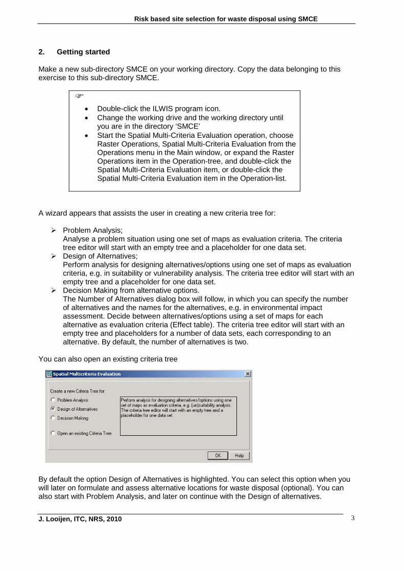
A wizard appears that assists the user in creating a new criteria tree for: Problem Analysis;
Analyse a problem situation using one set of maps as evaluation criteria. The criteria tree editor will start with an empty tree and a placeholder for one data set.
Design of Alternatives; Perform analysis for designing alternatives/options using one set of maps as evaluation criteria, e.g. in suitability or vulnerability analysis. The criteria tree editor will start with an empty tree and a placeholder for one data set.
Decision Making from alternative options. The Number of Alternatives dialog box will follow, in which you can specify the number of alternatives and the names for the alternatives, e.g. in environmental impact assessment. Decide between alternatives/options using a set of maps for each alternative as evaluation criteria (Effect table). The criteria tree editor will start with an empty tree and placeholders for a number of data sets, each corresponding to an alternative. By default, the number of alternatives is two.
You can also open an existing criteria tree
By default the option Design of Alternatives is highlighted. You can select this option when you will later on formulate and assess alternative locations for waste disposal (optional). You can also start with Problem Analysis, and later on continue with the Design of alternatives.
Risk based site selection for waste disposal using SMCE
J. Looijen, ITC, NRS, 2010 4
• Select Problem Analysis or Design of Alternatives. • Press OK.
The SMCE window appears. The SMCE window consists of a:
• Title bar with the name of the criteria tree (By default: ‘New Goal’) • Menu bar. The SMCE window has seven menus, File, Edit, Mode, Analysis,
Generate, View and Help. • Toolbar, by default located just below the menu bar. The toolbar provides shortcuts
for some regularly used menu commands (see also SMCE Help window, toolbar).
Point to each item and the name of the command and a short description at the bottom of the status bar will appear.
• Criteria tree viewer to show and/or edit the criteria tree and to standardize and weigh
the items of the tree. • Status bar located at the bottom of the SMCE window. The status bar gives brief
explanations on highlighted menu commands, the functionality of buttons in the toolbar and on selected items in the criteria tree.
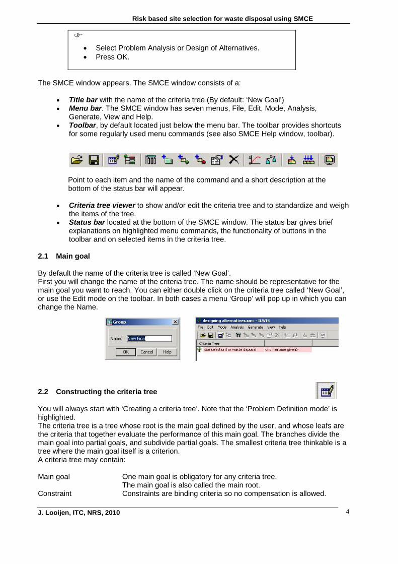
2.1 Main goal By default the name of the criteria tree is called ‘New Goal’. First you will change the name of the criteria tree. The name should be representative for the main goal you want to reach. You can either double click on the criteria tree called ‘New Goal’, or use the Edit mode on the toolbar. In both cases a menu ‘Group’ will pop up in which you can change the Name.
2.2 Constructing the criteria tree You will always start with ‘Creating a criteria tree’. Note that the ‘Problem Definition mode’ is highlighted. The criteria tree is a tree whose root is the main goal defined by the user, and whose leafs are the criteria that together evaluate the performance of this main goal. The branches divide the main goal into partial goals, and subdivide partial goals. The smallest criteria tree thinkable is a tree where the main goal itself is a criterion. A criteria tree may contain: Main goal One main goal is obligatory for any criteria tree. The main goal is also called the main root. Constraint Constraints are binding criteria so no compensation is allowed.

Risk based site selection for waste disposal using SMCE
J. Looijen, ITC, NRS, 2010 5
Areas in an input map (added as a constraint) that do not satisfy a constraint condition, will obtain a composite index value of 0, no matter how well these areas perform in any other criterion (factor). Constraints can only appear directly under the main goal.
Factor Factors allow for compensation. Poor performance in one criterion can be compensated by good performance in another criterion. Factors may appear directly under the main goal or under a group of factors (sub-goal). A factor can be a benefit (the higher the value, the better), or a cost (the higher the value, the worse).
Group of Factors A Group defines an intermediate or a partial goal. Under a Group, you can add one or more Factors and/or other Groups of Factors. Click the plus sign in front of a Group of Factors to expand the group.
For more details on the creation and filling of a criteria tree, refer to the Help function, Criteria tree viewer.

Risk based site selection for waste disposal using SMCE
J. Looijen, ITC, NRS, 2010 6
3. Site selection using spatial and thematic priorities First you will construct a criterion tree, identifying and structuring the spatial constraints and factors that should be considered for the site selection (problem structuring). The information needed for each criterion is added to the criterion tree (input maps and/or tables). Also, names for the different output maps are incorporated. Next, you have to convert the values and classes of each criterion into a common scale (standardisation) using different value functions. Then different priorities (weights) will be assigned to each criterion map and to a group of criteria maps according to different policy visions. After standardisation and weight assignment you will obtain the overall suitability of each pixel in the map for solid waste disposal (composite index map), based on the different visions. Finally you will analyse and display for each vision which of the suitable areas are large enough to store the waste for a prolonged period. The proposed site should be more than one hectare. 3.1 Main goal First you will change the name of the criteria tree. The name should be representative for the main goal you want to reach (see also section 2.1).
• Change the default name into ‘Site selection for waste
disposal_equal vision’. • Save the criterion tree and call the output map the same,
‘Waste_disposal_equal’
3.2 Constraints and factors Before starting to design a criteria tree it should be clear which constraints and/or factors contribute to the main goal and which input data are linked to each constraint or factor.
- How are you going to construct the criteria tree?
- Which criteria are constraints and which one factors?
Constraints:
Factors:
- Is it necessary to define groups of factors? - If so, which groups would you make? - Which criteria are based on vulnerability features?

Risk based site selection for waste disposal using SMCE
J. Looijen, ITC, NRS, 2010 7
To insert new groups, factors or constraints you have to make sure you are in the Problem Definition mode. Select the main goal or select the sub goal under which you wish to insert your new group, or factor. Constraints can only be inserted under the main goal. Select the Insert command on the Edit menu, or use the corresponding buttons in the toolbar. The Insert Group, Insert Factor or Insert Constraint dialog box will appear. Insert constraints In this case, four constraints will be included: The waste disposal site should not be constructed on landslides which are active or which may become active in the future (physical constraint). The waste disposal site should not be constructed within any build-up area (social constraint). The waste disposal site should not be constructed in lakes or riverbeds. The waste disposal site should have an area of at least 1 hectare.
This last constraint will not be part of the criteria tree however, as it concerns the output of the suitability assessment for waste disposal. Only the very suitable sites of at least 1 ha will be selected. This analysis occurs outside the SMCE mode.
• Select Insert constraint. • Name the constraint ‘Slide’. • Repeat the same for the other two constraints. Name them
‘Build-up area’ and ‘Lake_riverbed’. • Save your criteria tree.
Insert factors The objectives are grouped into the following groups and related factors (criteria): • Soil
⇒ Clay% ⇒ Thickness ⇒ Permeability
• Ecological function ⇒ Land use (Forest)
• Quality of life ⇒ Distance from build-up area
• Economic value ⇒ Land use (Coffee and Pasture) ⇒ Slope ⇒ Distance from city centre
Note that the groups Soil and Economic value each exist of three sub-factors!
Why are the factors ‘Slope’ and ‘Distance to city centre’ part of the group Economic value?

Risk based site selection for waste disposal using SMCE
J. Looijen, ITC, NRS, 2010 8
• Create a criteria tree according to the above-mentioned
groups. Start to insert the 4 groups. Next, highlight each group and insert the factors belonging to that group.
• Save your criteria tree.
Your criteria tree should look like the one presented below.
Why is the criterion ‘distance from city ‘centre’ a cost and ‘distance from build-up area’ a benefit? 3.3 Input maps For each factor and for each constraint, an input map or an input attribute column has to be selected. All input maps must be raster maps with the same georeference. The input maps or the input attribute columns may use any of the following domain types: any value domain, any class domain or system domain Bool. Input maps are added in the right part of the criteria tree, in the pinkish sections. The green sections are optional. You can select an input map by double clicking on the pinkish ‘row’ belonging to the criterion, or use the Edit – Edit Enter mode on the toolbar. Select from the dialog box the relevant map or table. To select an attribute table, click on the + in front of the map and select the relevant columns of the attribute table.
Risk based site selection for waste disposal using SMCE
J. Looijen, ITC, NRS, 2010 9
• Add the relevant map or table to each criterion. • Save the criteria tree.
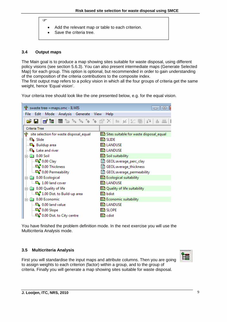
3.4 Output maps The Main goal is to produce a map showing sites suitable for waste disposal, using different policy visions (see section 5.6.3). You can also present intermediate maps (Generate Selected Map) for each group. This option is optional, but recommended in order to gain understanding of the composition of the criteria contributions to the composite index. The first output map refers to a policy vision in which all the four groups of criteria get the same weight, hence ‘Equal vision’. Your criteria tree should look like the one presented below, e.g. for the equal vision.
You have finished the problem definition mode. In the next exercise you will use the Multicriteria Analysis mode. 3.5 Multicriteria Analysis First you will standardise the input maps and attribute columns. Then you are going to assign weights to each criterion (factor) within a group, and to the group of criteria. Finally you will generate a map showing sites suitable for waste disposal.
Risk based site selection for waste disposal using SMCE
J. Looijen, ITC, NRS, 2010 10
3.5.1 Standardisation In the Problem Definition mode, you have selected input data for your criteria (factors or constraints). These input data are various maps or attribute columns with a value domain, a class domain, or the Bool domain. The values in these input maps or columns express different measurement units (e.g. distance, land use classes, percentages, etc.). In order to compare criteria with each other in a way that makes sense, they have to be standardised, i.e. transformed to the same unit. Moreover, different standardisation methods express different utility of input values. When standardising, depending on the type of input map, a dialog box will appear in which you can choose the "value function" by which the map or column values are converted to values between 0 and 1. Standardisation possibilities are slightly different for factors and for constraints: • Standardisation of factors (benefits and costs): the output values range between 0 and 1. • Standardisation of constraints: the output values are either 0 or 1. Depending on the domain of the map or attribute column, one of the Standardize dialog boxes will appear: For value maps: Standardize Value Input. For class maps: Standardize Class Input. For boolean maps: Standardize Boolean Input. A Standardize dialog box will only appear when you are in the Multicriteria Analysis mode, and when you selected a factor or constraint in the criteria tree viewer, and do one of the following: choose Standardize from the Analysis menu in the SMCE window, or click the Standardize button in the toolbar of the SMCE window, or click a criteria with the right mouse button and choose Standardize from the
context-sensitive menu, or press the Enter Key, or double-click a factor or constraint in the criteria tree viewer. For more information and examples of standardization refer to the HELP window, Standardize. Start Multicriteria Analysis.
• Open the Multicriteria Analysis mode

Risk based site selection for waste disposal using SMCE
J. Looijen, ITC, NRS, 2010 11
3.5.2 Standardisation of constraints Unlike factor standardisation, standardised constraints cannot be compensated by good performance of other criteria. Standardised constraints will either obtain a value 0 (not performing, FALSE) or a value 1 (performing, TRUE).
Standardization of the constraint Slide
What type of domain has the map Slide?
• Click on the constraint ‘Slide’ in the criteria tree • Choose/select standardize
The Standardize Class Input window appears. • Click on the ‘Add Attribute’ icon besides the Boolean Attribute
box(see red arrow). • The ‘Add Attribute’ box opens. • Add an attribute name, e.g. ‘slide’. • Enter the proper suitability values for the constraint slide.
Note that a value 0 becomes ‘False’and 1 becomes ‘True’. • When finished close the table. You will be back in the Standardize
Class Input window. • Click OK • Save the criteria tree.
Note: You can use the ‘Refresh attribute list’ option if you change one or more attribute values in the attribute table.
Repeat the same procedure for the constraints ‘Build up area’ and ‘Lake and riverbed’. Do not forget to save the criterion tree when finished.
Risk based site selection for waste disposal using SMCE
J. Looijen, ITC, NRS, 2010 12
3.5.3 Standardisation of factors The output values will range between 0 and 1 when you are dealing with standardisation of factors (benefits and costs). Bad performance in one criterion can be compensated by good performance in another criterion. Depending on the domain of the map or attribute column, a Standardise dialog box for a class input, a value input or a Boolean input will appear. If your input map or table has a value domain, you have to realise next whether your factor is a benefit or cost! Standardization of the factor texture (clay content) of the group soil
What type of domain has the column average % of clay of the attribute table Geol? Domain type: For standardization of value factors, you must select one of the following standardization functions: • Maximum • Interval • Goal • Convex • Concave • Combination (U- or S-shape curves) For more information and examples of standardization of value factors refer to the HELP window, Standardize Value.
• Click on the factor ‘Clay’ in the criteria tree • Choose/select standardize
The Standardize Value Input window appears. • Select maximum.
Click OK • Save the criteria tree
- Is the factor ‘percentage of clay’ a cost or a benefit? - Why did you select maximum and not goal or interval standardization, or even convex or concave? Standardization of the factor thickness of the group soil
What type of domain has the column average thickness of the attribute table Geol? Domain type:

Risk based site selection for waste disposal using SMCE
J. Looijen, ITC, NRS, 2010 13
• Click on the factor ‘Thickness’ in the criteria tree • Choose/select standardize
The Standardize Value Input window appears. • Select goal.
Enter the proper minimum value. Leave the default value for the maximum (40). Click OK
• Save the criteria tree.
- Is the factor ‘thickness’’ a cost or a benefit? - Why did you enter a minimum goal value and not a maximum goal value? Standardization of the factor permeability of the sub-group soil
What type of domain has the column average permeability of the attribute table Geol?
• Click on the factor ‘Permeability’ in the criteria tree • Choose/select standardize
The Standardize Value Input window appears. • Select goal.
Enter the proper maximum value. Leave the default value for the minimum (0).
• Click OK • Save the criteria tree.
- Is the factor ‘permeability’’ a cost or a benefit? - Why did you enter a maximum goal value and not a minimum goal value? Standardization of the factor land cover of the group Ecology
What type of domain has the map Landuse? Specify a column in an attribute table that matches class names to values between 0 and 1. The attribute column can still be created; values in the attribute column must be between 0 and 1.

Risk based site selection for waste disposal using SMCE
J. Looijen, ITC, NRS, 2010 14
• Click on the factor ‘Landcover’ in the criteria tree • Choose/select standardize
The Standardize Class Input window appears. • Click on ‘Édit’.
The attribute table of the map Landuse emerges. • Add a column ‘st_ecology’. • Enter the proper suitability values for the factor landcover (Forest, Lake &
riverbed). • When finished close the table. You will be back in the Standardize Class
Input window. • Select the column ‘st_ecology’ under Attribute between 0 and 1 (Refresh
the attribute table, if necessary). • Click OK • Save the criteria tree.
Note: You can also use the Apply weigh wizard’ option to enter the different values in the table!
Standardization of the factor Build-up area of the group Quality of life
• Click on the factor ‘Build-up area in the criteria tree • Choose/select standardize
The Standardize Value Input window appears. • Select goal.
Enter the proper minimum value. Leave the default value for the maximum (1278). Click OK
• Save the criteria tree.
Standardization of the factor Landvalue of the group Economy
• Click on the factor ‘Landvalue’ in the criteria tree • Choose/select standardize
The Standardize Class Input window appears. • Click on ‘Édit’.
The attribute table of the map Landuse emerges. • Add a new column ‘st_economic’. • Enter the proper suitability values for the factor Landvalue (Coffee &
Pasture). • When finished close the table. You will be back in the Standardize Class
Input window. • Select the column ‘st_economic’ under Attribute between 0 and 1
(Refresh the attribute table, if necessary). • Click OK • Save the criteria tree.

Risk based site selection for waste disposal using SMCE
J. Looijen, ITC, NRS, 2010 15
Standardization of the factor slope of the group Economy Question
What type of domain has the map Slope?
• Click on the factor ‘Slope’ in the criteria tree • Choose/select standardize
The Standardize Value Input window appears. • Select goal.
Enter the proper maximum value. Leave the default value for the minimum (0).
• Click OK • Save the criteria tree.
Standardisation of the factor City centre of the group Economy
• Click on the factor ‘City centre’ in the criteria tree • Choose/select standardize
The Standardize Value Input window appears. • Select goal.
Enter the proper maximum value. Leave the default value for the minimum (0).
• Click OK • Save the criteria tree.
What value function would you select if the waste disposal site should be within 2 km from the city centre, but the nearer, the better according to a logarithmic function? Add the proper value function below.
Risk based site selection for waste disposal using SMCE
J. Looijen, ITC, NRS, 2010 16
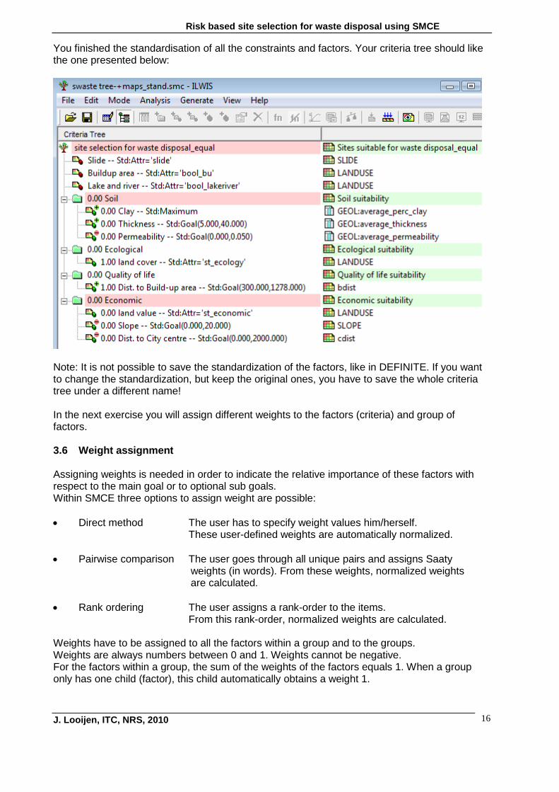
You finished the standardisation of all the constraints and factors. Your criteria tree should like the one presented below:
Note: It is not possible to save the standardization of the factors, like in DEFINITE. If you want to change the standardization, but keep the original ones, you have to save the whole criteria tree under a different name! In the next exercise you will assign different weights to the factors (criteria) and group of factors. 3.6 Weight assignment Assigning weights is needed in order to indicate the relative importance of these factors with respect to the main goal or to optional sub goals. Within SMCE three options to assign weight are possible: • Direct method The user has to specify weight values him/herself.
These user-defined weights are automatically normalized. • Pairwise comparison The user goes through all unique pairs and assigns Saaty
weights (in words). From these weights, normalized weights are calculated.
• Rank ordering The user assigns a rank-order to the items.
From this rank-order, normalized weights are calculated. Weights have to be assigned to all the factors within a group and to the groups. Weights are always numbers between 0 and 1. Weights cannot be negative. For the factors within a group, the sum of the weights of the factors equals 1. When a group only has one child (factor), this child automatically obtains a weight 1.

Risk based site selection for waste disposal using SMCE
J. Looijen, ITC, NRS, 2010 17
A Weigh dialog box will appear when you are in the Multicriteria Analysis mode, and when you selected the main goal, or a sub goal, that contains multiple factors in the criteria tree viewer, and do one of the following: choose Weigh from the Analysis menu in the SMCE window, or click the Weigh button in the toolbar of the SMCE window, or click a criteria with the right mouse button and choose Weigh from the context-sensitive
menu, or press the Enter Key, or click the main goal or a sub goal in the criteria tree viewer. When you use Weigh for the first time, the Weigh dialog box will appear, in which you can choose the Weigh method. Also, within one of the three weigh methods dialog boxes, you can choose another weigh method by using the Choose other method button. The selected Weigh dialog box will appear. For more information and examples of weight assignment methods refer to the SMCE HELP window, Weigh.
Why is there no need to assign weights to the three constraints? 3.6.1 Assign weights to the factors within the group Soil The geomorphologist in consultation with a local soil expert determined the following weights:
Factor Weight Clay % 40 Thickness 40 Permeability 20
• Click on the group ‘Soil’ in the criteria tree • Choose/select Weigh
The Weigh window appears. • Select Direct. • Enter the weigh values to each soil factor (Clay%, Thickness &
Permeability). • Click OK • Save the criteria tree.

Risk based site selection for waste disposal using SMCE
J. Looijen, ITC, NRS, 2010 18
What weights would you assign when you deal with soils with a very thick clay layer, but that are, depending on the hydrological conditions, prone to shrink and swell? 5.6.2 Assign weights to the factors within the group Economy The geologist and engineer in consultation with the local planners determined the following rank order in weights: 1. land value, 2. city centre, 3. slope.
• Click on the group factor ‘Economy’ in the criteria tree • Choose/select Weigh
The Weigh window appears. • Select Rank Order. • Select Expected Value. • Enter the ranking for each group factor. • Click OK • Save the criteria tree.
You have finished weight assignment to factors within a group. This is often based on expert knowledge. Next, you will assign weights to the different groups. Such groups may represent different policies or stakeholder visions. The simplest policy is ‘all groups are equally important’. In other words, assign equal weights to all the groups.

Risk based site selection for waste disposal using SMCE
J. Looijen, ITC, NRS, 2010 19
You may also explore what might be the best location(s) for solid waste if you consider soil and ecological factors more important than quality of life and economical factors, or the other way around. 5.6.3 Assign weights to the various groups according to different visions Stakeholders representing different interests within the area were asked to rank the four group criteria Soil, Ecology, Quality of life and Economy. Their views are summarised in the following visions:
Groups Equal Nature Ecology Human Economy Soil 0.25 0.5 0.3 0.2 0.2 Ecological 0.25 0.3 0.5 0.1 0.1 Quality of life 0.25 0.1 0.1 0.5 0.2 Economical 0.25 0.1 0.1 0.2 0.5
Assign weights to the four groups according to the above-mentioned five visions.
• Click on the main goal ‘Site selection for waste disposal’ in the criteria
tree. • Give the overall composite index map a logical short name (without
spaces!), e.g. Equal. You can do this using right mouse button and click on edit).
• Choose/select Weigh The Weigh window appears.
• Select Direct. • Enter the weigh values to each group according to the Equal weight
policy. • Click OK • Save the criteria tree. Use a logic name, like ‘Equal’. • Repeat the same for the other four policies. Save them under
different (logical) names!
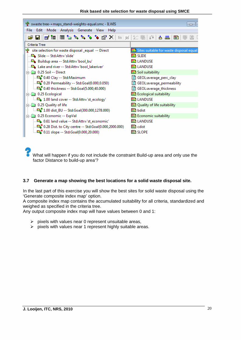
Note that you can also use the expected value method or pairwise comparison method to assign weights! You have finished the main MCA part of the exercise. Your criterion tree should look like the one presented below, for the Equal weight vision.
Risk based site selection for waste disposal using SMCE
J. Looijen, ITC, NRS, 2010 20
What will happen if you do not include the constraint Build-up area and only use the factor Distance to build-up area’? 3.7 Generate a map showing the best locations for a solid waste disposal site. In the last part of this exercise you will show the best sites for solid waste disposal using the ‘Generate composite index map’ option. A composite index map contains the accumulated suitability for all criteria, standardized and weighed as specified in the criteria tree. Any output composite index map will have values between 0 and 1: pixels with values near 0 represent unsuitable areas, pixels with values near 1 represent highly suitable areas.
Risk based site selection for waste disposal using SMCE
J. Looijen, ITC, NRS, 2010 21
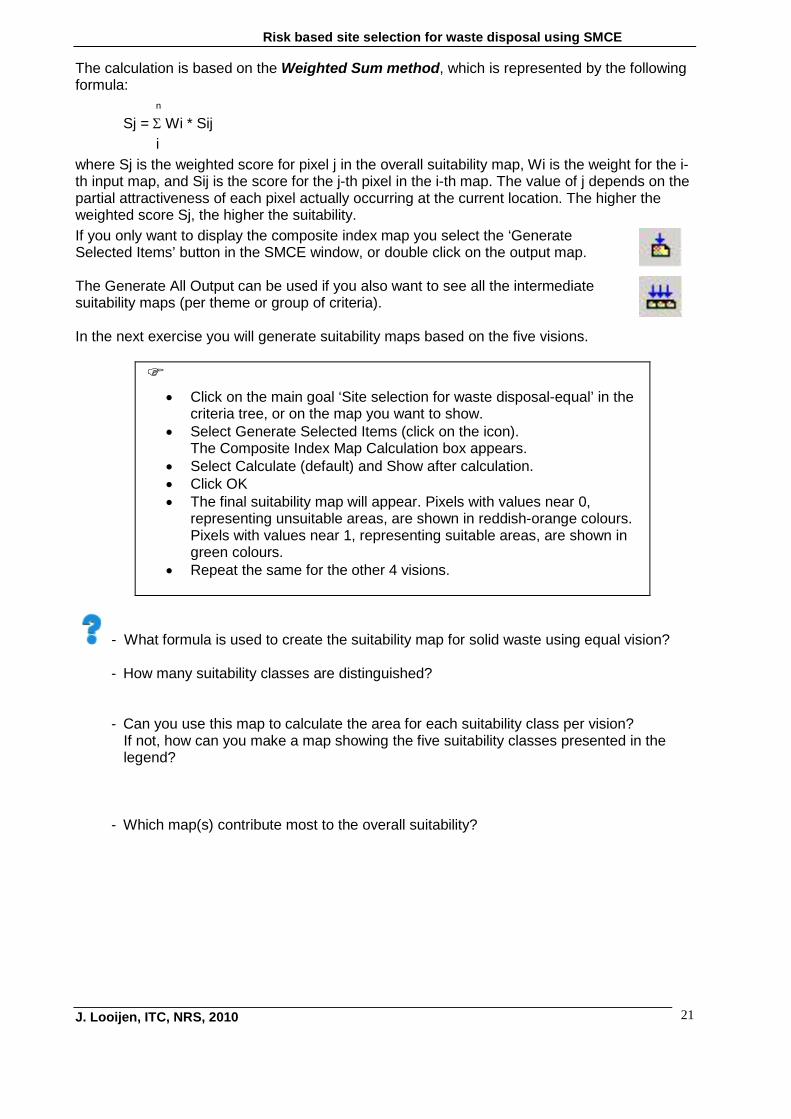
The calculation is based on the Weighted Sum method, which is represented by the following formula:
n
Sj = Σ Wi * Sij i
where Sj is the weighted score for pixel j in the overall suitability map, Wi is the weight for the i-th input map, and Sij is the score for the j-th pixel in the i-th map. The value of j depends on the partial attractiveness of each pixel actually occurring at the current location. The higher the weighted score Sj, the higher the suitability. If you only want to display the composite index map you select the ‘Generate Selected Items’ button in the SMCE window, or double click on the output map. The Generate All Output can be used if you also want to see all the intermediate suitability maps (per theme or group of criteria). In the next exercise you will generate suitability maps based on the five visions.
• Click on the main goal ‘Site selection for waste disposal-equal’ in the
criteria tree, or on the map you want to show. • Select Generate Selected Items (click on the icon).
The Composite Index Map Calculation box appears. • Select Calculate (default) and Show after calculation. • Click OK • The final suitability map will appear. Pixels with values near 0,
representing unsuitable areas, are shown in reddish-orange colours. Pixels with values near 1, representing suitable areas, are shown in green colours.
• Repeat the same for the other 4 visions.
- What formula is used to create the suitability map for solid waste using equal vision?
- How many suitability classes are distinguished?
- Can you use this map to calculate the area for each suitability class per vision? If not, how can you make a map showing the five suitability classes presented in the legend? - Which map(s) contribute most to the overall suitability?

Risk based site selection for waste disposal using SMCE
J. Looijen, ITC, NRS, 2010 22
4. Suitable site capacity In the next exercise you will reclassify the five vision maps and calculate the area for each suitability class. Then you will select within the best suitable (only the HS class) sites those areas that cover at least 1 ha. Use the following suitability classes: NS Not suitable 0 MaS Marginally suitable 0-0.25 MoS Moderately suitable 0.25-0.5 S Suitable 0.5-0.75 HS Highly suitable 0.75-1 Note that this step is not carried out in the SMCE mode of ILWIS!
• Reclassify the Equal vision map into the five suitability classes. • Calculate the area for each suitability class in ha. • Repeat the same for the other four vision maps. • Create one table showing for the five visions the area in ha of each
suitability class. • Select for each vision only those areas that are Highly suitable (or the
best suitable next class), and at least 1 ha. Give logical names to the maps, e.g. Equal_suit for the Equal vision, Nature_suit for the Nature vision, etc.
• Compare the five suitability maps. • Compare the five suitability maps with the Boolean logic model map
of the demonstration.
- Can you produce one map showing the best locations for waste disposal according to the five visions? If yes, explain your answer and include the formula.
- Which site(s) would you recommend and why? Show it on a map (use an arrow or other indication tool). - Which other criterion could have been included in the assessment and how would you define the value function?