sistemas de drenagem de Águas pluviais (detention … · du - 52 sistemas de drenagem de Águas...
TRANSCRIPT

DU - 50
SISTEMAS DE DRENAGEM DE ÁGUAS PLUVIAIS
BACIAS DE RETENÇÃO (Detention ponds)
ADVANTAGES
• Cost
• Expansion flexibility
Objectivos – ART. 176º
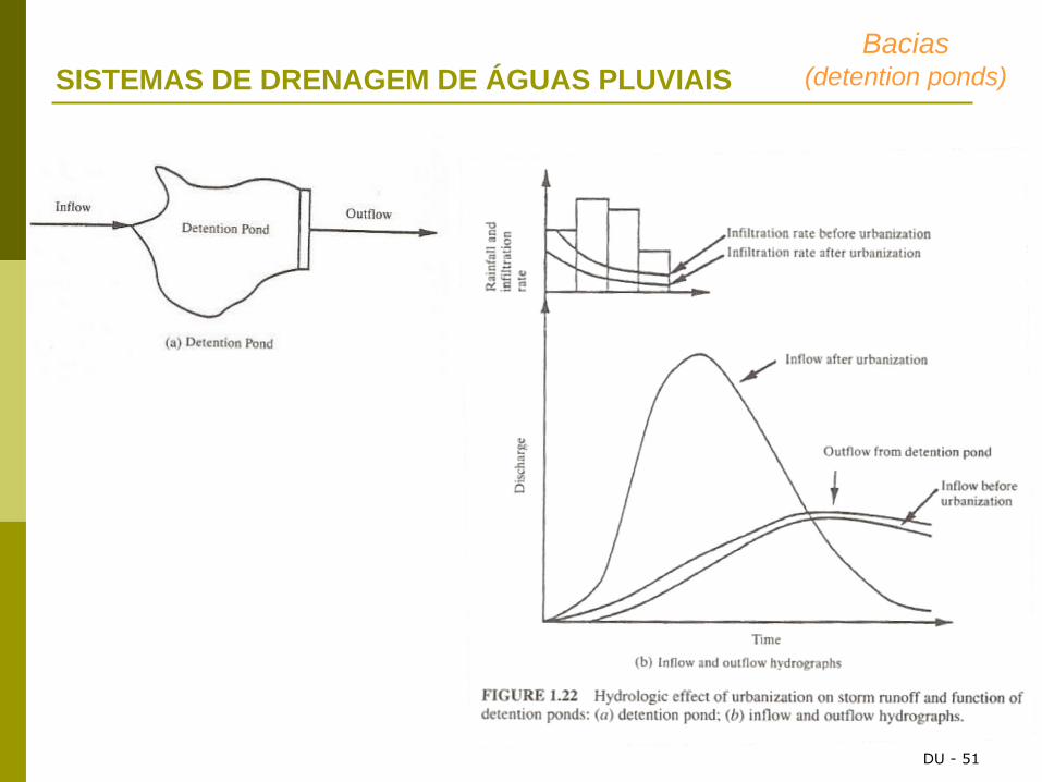
• reduction flood risks
• creation leisure areas (for fishing e boating…)
• making water store areas (agriculture, fire fighting, industries, municipal street washing,
parks irrigation …)
• Environmental protection (reduction of suspended solids and organic mater)
Bacias (detention ponds)
DU - 51
SISTEMAS DE DRENAGEM DE ÁGUAS PLUVIAIS
Bacias (detention ponds)
DU - 52
SISTEMAS DE DRENAGEM DE ÁGUAS PLUVIAIS
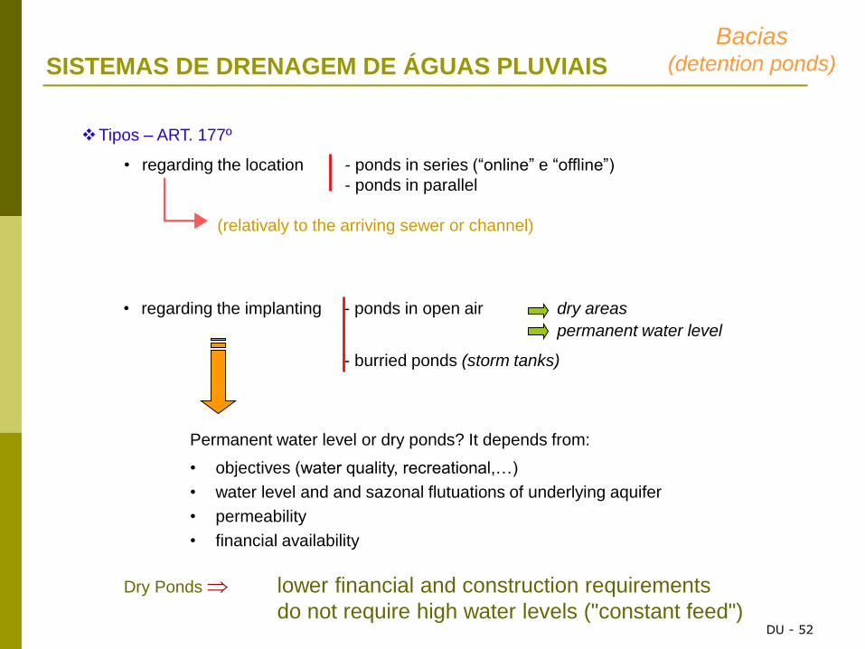
• regarding the implanting - ponds in open air dry areas
permanent water level
- burried ponds (storm tanks)
Permanent water level or dry ponds? It depends from:
• objectives (water quality, recreational,…)
• water level and and sazonal flutuations of underlying aquifer
• permeability
• financial availability
Dry Ponds lower financial and construction requirements
do not require high water levels ("constant feed")
Tipos – ART. 177º
• regarding the location - ponds in series (“online” e “offline”)
- ponds in parallel
(relativaly to the arriving sewer or channel)
Bacias (detention ponds)

DU - 53
SISTEMAS DE DRENAGEM DE ÁGUAS PLUVIAIS
Constituição – ART. 178º
• Pond main body bottom and earth verge
covered embankments with vegetation cover (landscaping)
• Dischage devices Bottom discharge
Work head and output
Sewer
• Safety Devices Surface discharge
Detention pond deployment)
• take advantage area with natural depression;
• At the work head of the detention pond construct a concrete chamber (to avoid
damages in pipe bed and / or clogging with dirt and other sediments)
• trace transverse and longitudinal profiles to build the curve of volumes stored (calculate
volume of stored water for different water levels)
• check that the high water level allowed ensures the sizing volume that is needed.
Bacias (detention ponds)
DU - 54
SISTEMAS DE DRENAGEM DE ÁGUAS PLUVIAIS
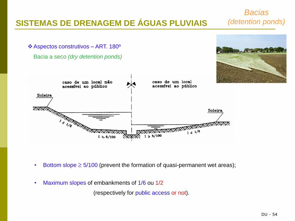
Aspectos construtivos – ART. 180º
Bacia a seco (dry detention ponds)
• Bottom slope 5/100 (prevent the formation of quasi-permanent wet areas);
• Maximum slopes of embankments of 1/6 ou 1/2
(respectively for public access or not).
Bacias (detention ponds)

DU - 55
SISTEMAS DE DRENAGEM DE ÁGUAS PLUVIAIS
Ponds with permanent water level:
• Minimum water level of 1,5 m (avoid excessivo aquatic plants development and
ensure any fish life)
• ensure appropriate treatment of verges (embankments lawns, etc ...)
Bacias (detention ponds)

DU - 56
SISTEMAS DE DRENAGEM DE ÁGUAS PLUVIAIS
Water Quality
Improve water quality of stormwater received
Occur transformations of physical, chemical and microbiological
• Sedimentation of suspended soils reduction of water turbidity
• Variation of DO of the water body balance between “inputs” (rearation and
fotosinthesis) and consumption
• variation of the nutrients (N, P) plants behaviour and impacts
• Reduction of microrganisms solar radiation, biologic competion,
temperature e sedimentation
Typical impact:
Bacias (detention ponds)
DU - 57
SISTEMAS DE DRENAGEM DE ÁGUAS PLUVIAIS
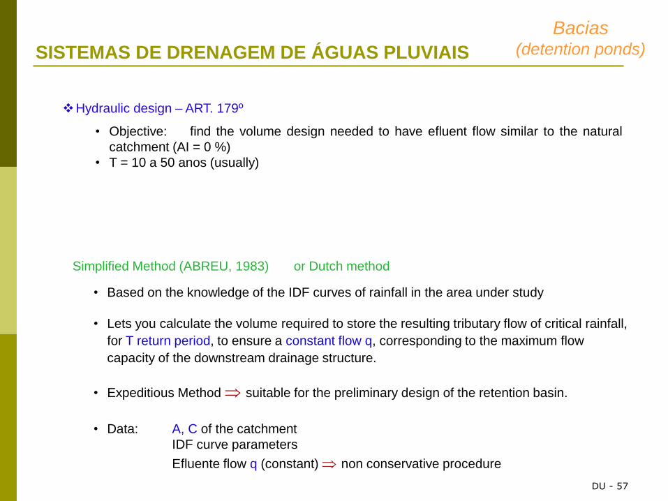
Simplified Method (ABREU, 1983) or Dutch method
• Based on the knowledge of the IDF curves of rainfall in the area under study
• Lets you calculate the volume required to store the resulting tributary flow of critical rainfall,
for T return period, to ensure a constant flow q, corresponding to the maximum flow
capacity of the downstream drainage structure.
• Expeditious Method suitable for the preliminary design of the retention basin.
• Data: A, C of the catchment
IDF curve parameters
Efluente flow q (constant) non conservative procedure
Hydraulic design – ART. 179º
• Objective: find the volume design needed to have efluent flow similar to the natural
catchment (AI = 0 %)
• T = 10 a 50 anos (usually)
Bacias (detention ponds)

DU - 58
SISTEMAS DE DRENAGEM DE ÁGUAS PLUVIAIS
Bacias (detention ponds)
DU - 59
SISTEMAS DE DRENAGEM DE ÁGUAS PLUVIAIS
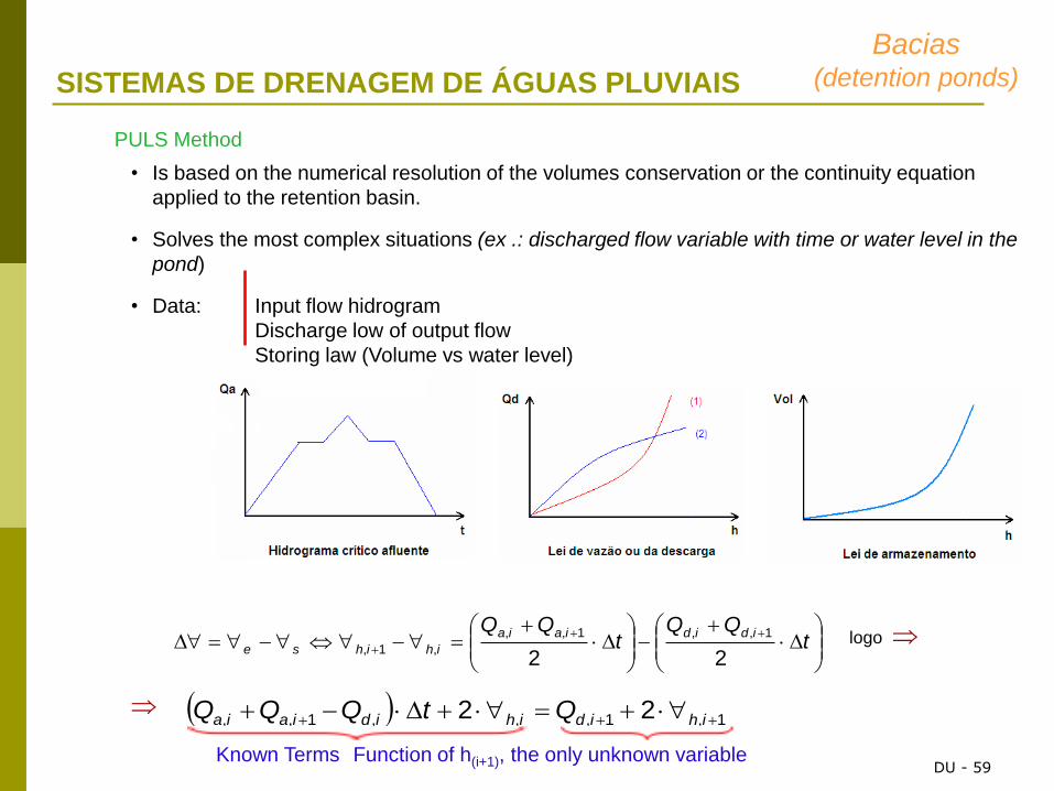
PULS Method
• Is based on the numerical resolution of the volumes conservation or the continuity equation
applied to the retention basin.
• Solves the most complex situations (ex .: discharged flow variable with time or water level in the
pond)
• Data: Input flow hidrogram
Discharge low of output flow
Storing law (Volume vs water level)
tQQ
tQQ ididiaia
ihihse22
1,,1,,
,1,
1,1,,,1,, 22 ihidihidiaia QtQQQ
logo
Known Terms Function of h(i+1), the only unknown variable
Bacias (detention ponds)

DU - 60
SISTEMAS DE DRENAGEM DE ÁGUAS PLUVIAIS
Bacias (detention ponds)
𝒊 =𝒂
(𝑻𝑫 + 𝒃)𝑪
𝑸𝑷 = 𝑪 𝒊 𝑨
Peak discharge rate:
Inflow hydrograph volume:
Precipitation Intensity:
𝑽𝒊 = 𝟔𝟎 𝟎, 𝟓 𝑸𝑷 𝑻𝑫 − 𝒕𝒄 + 𝑻𝑫 + 𝒕𝒄
Outflow hydrograph volume:
Detention storage volume :
𝑽𝒐 = 𝟔𝟎 𝟎, 𝟓 𝑸𝑨 𝑻𝑫 + 𝒕𝒄
𝑽𝒔 = 𝑽𝒊−𝑽𝒐= 𝟔𝟎 𝑸𝑷𝑻𝑫 − 𝟑𝟎𝑸𝑨 𝑻𝑫 + 𝒕𝒄
The rainfall duration TD for maximum retention volume is
determined by differentiating Vs with respect to TD:
𝑻𝑫 𝟏 − 𝒄 + 𝒃
𝑻𝑫 + 𝒃 (𝒄+𝟏)−
𝑸𝑨
𝟐𝑪𝑨= 𝟎

DU - 61
SISTEMAS DE DRENAGEM DE ÁGUAS PLUVIAIS
INFILTRATION CHAMBERS
Purpose
• store and infiltration of stormwater;
economic solution and effective, suitable for permeable soil areas;
Kinds of systems

DU - 62
SISTEMAS DE DRENAGEM DE ÁGUAS PLUVIAIS
Infiltration
Chambers
Capacity (factors that depends):
• size of the the basin to drain;
• rainfall characteristics of the zone;
• degree of soil permeability;
• average slope of the basin drained;
• hydraulic conductivity of the soil.
Desadvantages
• not suitable for clay, silty or sandy-silty soils
• risk of contamination of aquifers caused by mixing of wastewater with rainwater
• high costs associated with the maintenance and operation (regular cleaning)
• high difficulty of rehabilitation
percolated water flow increases with the water level increase inside the
chambers (in the absence of soil sealing).
DU - 63
SISTEMAS DE DRENAGEM DE ÁGUAS PLUVIAIS
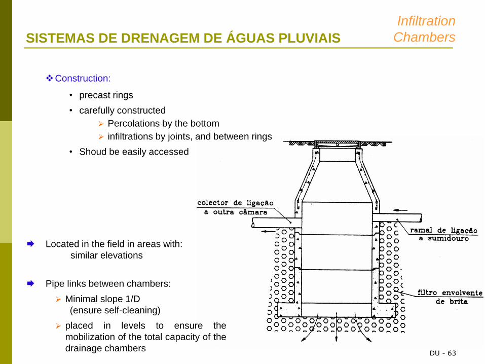
Construction:
• precast rings
• carefully constructed
Percolations by the bottom
infiltrations by joints, and between rings
• Shoud be easily accessed
Located in the field in areas with:
similar elevations
Pipe links between chambers:
Minimal slope 1/D
(ensure self-cleaning)
placed in levels to ensure the
mobilization of the total capacity of the
drainage chambers
Infiltration
Chambers

DU - 64
SISTEMAS DE DRENAGEM DE ÁGUAS PLUVIAIS
Hydraulic design
Assumptions considered:
• linearity between the hydraulic load on the bottom of the chamber and the flow
percolated;
• application of generalized rational method for determining the maximum flow rate (for a
given T);
• constant influent flow to each chamber during the critical precipitation and its precipitation
intensity;
• complete filling of the chamber, on the occurrence of the critical precipitation
Expressões de cálculo (ESCRITT, 1947)
Infiltration
Chambers

DU - 65
SISTEMAS DE DRENAGEM DE ÁGUAS PLUVIAIS
Metodologia de cálculo
Infiltration
Chambers

SWMM is a distributed, dynamic rainfall-runoff simulation
model used for single event or long-term (continuous) simulation
of runoff quantity and quality from primarily urban areas.
• The runoff component of
SWMM operates on a collection
of subcatchment areas that
receive precipitation and
generate runoff and pollutant
loads.
• The routing portion of SWMM
transports this runoff through a
system of pipes, channels,
storage/treatment devices,
pumps, and regulators.
DU - 66
Introduction to USEPA SWMM
67
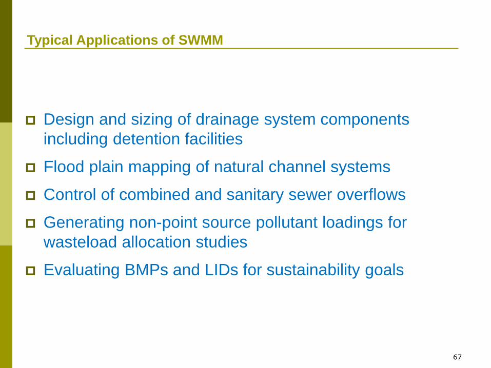
Typical Applications of SWMM
Design and sizing of drainage system components
including detention facilities
Flood plain mapping of natural channel systems
Control of combined and sanitary sewer overflows
Generating non-point source pollutant loadings for
wasteload allocation studies
Evaluating BMPs and LIDs for sustainability goals

68
Limitations of SWMM
Not applicable to large-scale, non-urban watersheds
Not applicable to forested areas or irrigated cropland
Cannot be used with highly aggregated (e.g., daily) rainfall data
Its an analysis tool, not an automated design tool

Processes Modeled by SWMM
DU - 69

SWMM Chronology
1971 - SWMM I (M&E, UF, WRE)
1975 - SWMM II (UF)
1981 - SWMM 3 (UF & CDM)
1983 - SWMM 3.3 (PC Version)
1988 - SWMM 4 (UF & CDM)
2005 – SWMM 5 (EPA & CDM)
DU - 70

Hydrologic Modeling Features
Hydrologic features:
• Spatially and time varying rainfall
• Evaporation of standing surface water
• Snow accumulation and melting
• Interception from depression storage
• Infiltration into soil layers
• Percolation into shallow groundwater
• Interflow between groundwater & channels
• Nonlinear routing of overland flow
The spatial variation is obtained by the prior definition of smaller subcatchments of the
study area, homogeneous in terms of their physical characteristics.
DU - 71

Hydraulic Modelling Features Hydraulic features:
• Handles drainage networks of any size
• Accommodates various conduit shapes as well
as irregular natural channels
• Models pumps, regulators, storage units
• Allows external inflows from runoff,
groundwater, RDII, sanitary, DWF, and user-
supplied time series
• Uses flexible rule-based controls for pumps
and regulators
• Models various flow regimes, such as
backwater, surcharging, reverse flow, and
surface ponding
DU - 72

Water Quality Modelling Features Water Quality features:
• Pollutant buildup over different land uses
• Pollutant washoff during runoff events
• Reduction in buildup from street cleaning
• Reduction in washoff from BMPs
• Inflows from user-defined sources and sanitary DWF
• WQ routing through the drainage network
• User-defined treatment functions
Graphic representation:
• GIS interface and the possibility of integration of coordinated plants
• Colour representation in plan and profile simulation over time
• Statistical analyses DU - 73

Chap 1 – Introduction
Chap 2 – Quick start tutorial
Chap 3 – SWMM´s conceptual model
Chap 4 – SWMM´s main window
Chap 5 - Working with Objects
Chap 6 – Working with Projects
Chap 7 – Working with the map
Chap 8 – Running a simulation
Chap 9 – Vieweing Results
Chap 10 – Printing and copying
Chap 11 – Files used by SWMM
Chap 12 – Using add-in tools
Apendix: A – Usefull tables
B – Visual object properties
C – Specialized properties editors
D – Command line SWMM
E – Error and warning messages
SWMM Manual
Very usefull for
quick start
Very usefull
to be consulted
DU - 74

Conceptualization model
Atmosphere
compartment
Land surface
compartment
Groundwater
compartment
Transport
compartment
Raingage objects: rainfall inputs
Subcathment objects
Node and link objects Aquifer objects
Precipitation falls / snow
Pollutants
Infiltration
Surface runoff
Pollutant loadings
Groundwater
interflow
Dry weather inflow
User defined hidrographs
DU - 75

76
SWMM 5’s Visual Objects
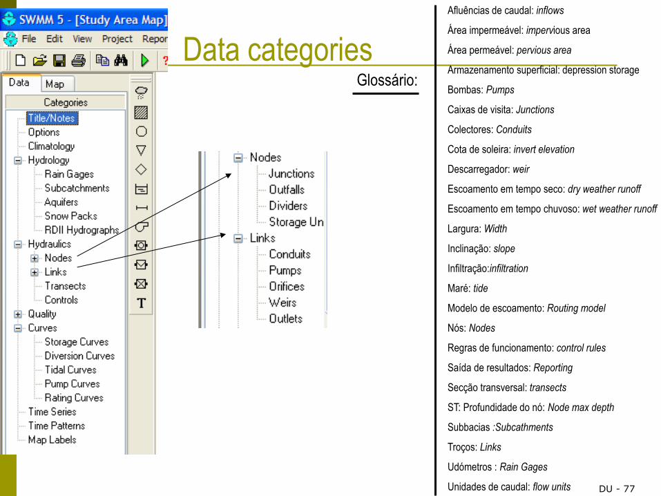
Data categories Glossário:
Afluências de caudal: inflows
Área impermeável: impervious area
Área permeável: pervious area
Armazenamento superficial: depression storage
Bombas: Pumps
Caixas de visita: Junctions
Colectores: Conduits
Cota de soleira: invert elevation
Descarregador: weir
Escoamento em tempo seco: dry weather runoff
Escoamento em tempo chuvoso: wet weather runoff
Largura: Width
Inclinação: slope
Infiltração:infiltration
Maré: tide
Modelo de escoamento: Routing model
Nós: Nodes
Regras de funcionamento: control rules
Saída de resultados: Reporting
Secção transversal: transects
ST: Profundidade do nó: Node max depth
Subbacias :Subcathments
Troços: Links
Udómetros : Rain Gages
Unidades de caudal: flow units DU - 77
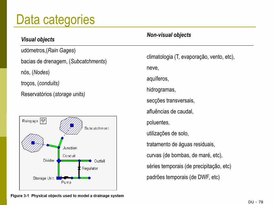
Data categories
Visual objects
udómetros,(Rain Gages)
bacias de drenagem, (Subcatchments)
nós, (Nodes)
troços, (conduits)
Reservatórios (storage units)
Non-visual objects
climatologia (T, evaporação, vento, etc),
neve,
aquíferos,
hidrogramas,
secções transversais,
afluências de caudal,
poluentes,
utilizações de solo,
tratamento de águas residuais,
curvas (de bombas, de maré, etc),
séries temporais (de precipitação, etc)
padrões temporais (de DWF, etc)
DU - 78

Cross section for conduits
DU - 79

Computational Methods
Surface Flow
Subcatchements Non linears storm tanks Evap P, snow
d
dP – dep storage
Q Q When d > dP
Q: Manning equation
Infiltration
Horton Equation
Necessário: taxas de infiltração máximas e mínimas, coeficiente de decaimento, tempo que demora o solo
saturado a secar
Green-Ampt Green-Ampt
Necessério: humidade inicial, conductividade hidráulica do solo, carga hidráulica na frente molhada
SCS Method (Curve Number)
Need to know the soil ocupation
DU - 80

Escoamento no subsolo (Groundwater)
Assume that the surface area of the ground is not
saturated with a given moisture content and the
deeper zone is saturated
Registam-se diversos fluxos
volume /(área.tempo)
DU - 81
Computational Methods

82
Flow Routing Algorithms in SWMM5
Steady Flow simple hydrograph translation applicable only to branched networks
Kinematic Wave gravity force balanced by friction force attenuated & delayed outflow due to channel
storage applicable only to branched networks
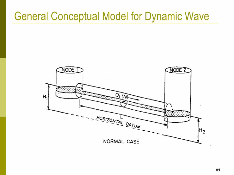
Dynamic Wave solves full St. Venant eqns. accounts for channel storage, backwater effects,
pressurized flow, and reverse flow applicable to any network layout requires smaller time step

83
Steady Flow Routing
Actually just sums instantaneous subcatchment runoff for all subcatchments upstream of the selected channel
Kinematic Wave
Uniform, unsteady flow
No backwater, no surcharge, tree branch systems only unless flow splits are input
Dynamic Wave
Non-uniform, unsteady flow
Backwater, surcharge, looped or parallel sewers, street routing of flooded sewer manholes
Flow Routing Algorithms in SWMM5
84
General Conceptual Model for Dynamic Wave
85
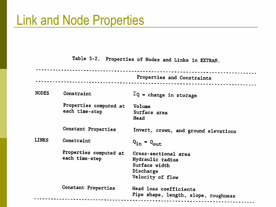
Link and Node Properties

86
Hydraulic Boundary Condition at Nodes
JN
JN+1
Grelev(NN,1)
Grelev(NN,2)
87
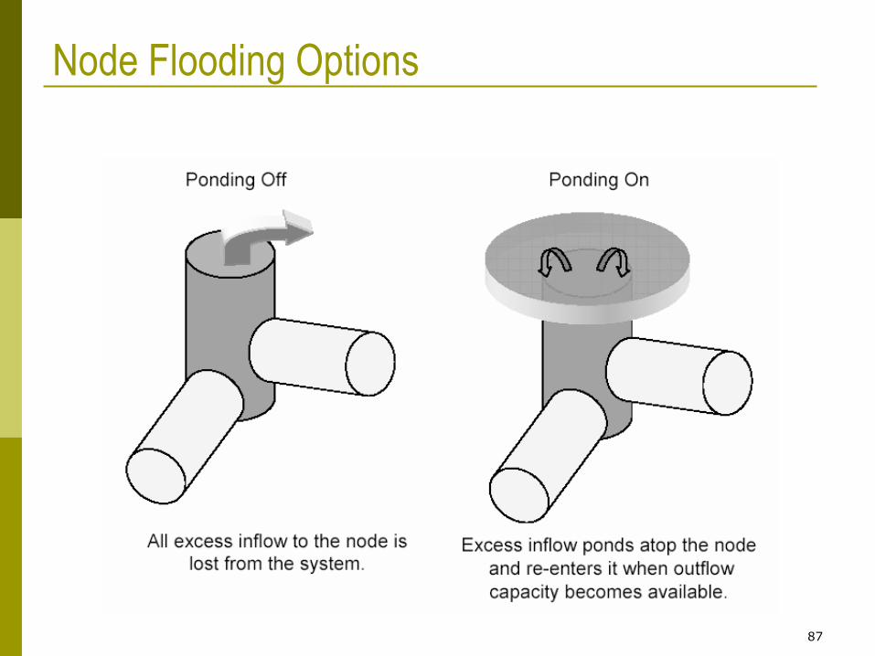
Node Flooding Options
88
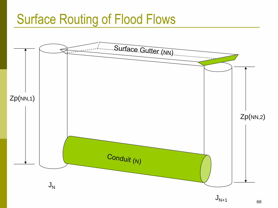
Surface Routing of Flood Flows
JN
JN+1
Zp(NN,1)
Zp(NN,2)

Métodos computacionais
Flow in the sewer system
Escoamento em pressão: Preissmann’s Slot approach
Necessário atentar ao passo de cálculo
Numerical Method: Picard iterations (explicit method) and variable time step dependent of Courant
stabilit condition
DU - 89

Simulation Necessário pré-definir uma série de opções
Geral: unidades, modelo de infiltração, modelo
hidráulico, se permite alagamento e se se pretende
relatório sobre as acções de controlo
Datas: início e fim da simulação, início da saída de
resultados, início e fim da limpeza de ruas (para estudos
de qualidade), período seco anterior
DU - 90

Simulation
Intervalos de tempo: escoamento em tempo de chuva
e em tempo seco, modelo hidrodinâmico e saída de
resultados; a verificar se ocorrerem erros na simulação
Ficheiros: referencia os ficheiros externos que se
pretende utilizar: de P, runoff, RDII, hotstart (usar os
resultados de outra simulação como condições de inicio para a presente
simulação)
DU - 91
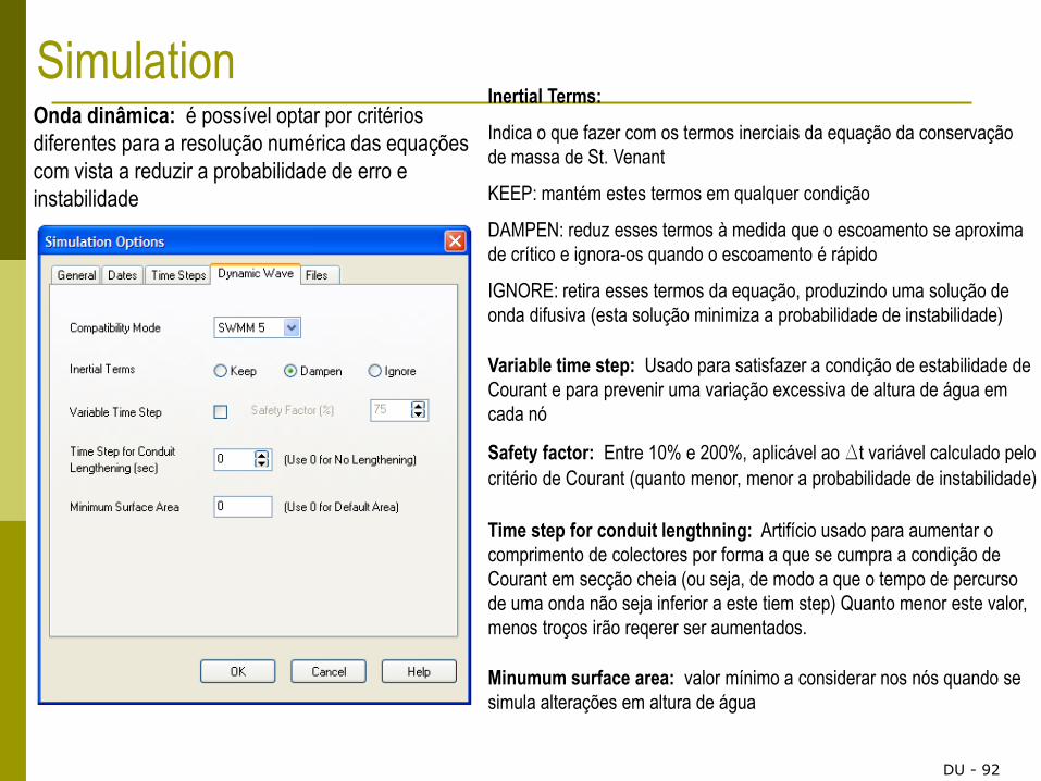
Simulation Onda dinâmica: é possível optar por critérios
diferentes para a resolução numérica das equações
com vista a reduzir a probabilidade de erro e
instabilidade
Inertial Terms:
Indica o que fazer com os termos inerciais da equação da conservação
de massa de St. Venant
KEEP: mantém estes termos em qualquer condição
DAMPEN: reduz esses termos à medida que o escoamento se aproxima
de crítico e ignora-os quando o escoamento é rápido
IGNORE: retira esses termos da equação, produzindo uma solução de
onda difusiva (esta solução minimiza a probabilidade de instabilidade)
Variable time step: Usado para satisfazer a condição de estabilidade de
Courant e para prevenir uma variação excessiva de altura de água em
cada nó
Safety factor: Entre 10% e 200%, aplicável ao Dt variável calculado pelo
critério de Courant (quanto menor, menor a probabilidade de instabilidade)
Time step for conduit lengthning: Artifício usado para aumentar o
comprimento de colectores por forma a que se cumpra a condição de
Courant em secção cheia (ou seja, de modo a que o tempo de percurso
de uma onda não seja inferior a este tiem step) Quanto menor este valor,
menos troços irão reqerer ser aumentados.
Minumum surface area: valor mínimo a considerar nos nós quando se
simula alterações em altura de água
DU - 92
94
Homework
1. Download SWMM5 from the EPA Website
http://www.epa.gov/ednnrmrl/models/swmm/index.htm
2. Download the User’s Manual
3. Page through the Users Manual so you are
familiar with it
4. Look at the tutorial and be prepared to run
it in class