siprotec 5 application voltage control of transformers in parallel operation€¦ · ·...
TRANSCRIPT
SIPROTEC 5 Application
Voltage Control of Transformers inParallel OperationSIP5-APN-034, Edition 2
www.siemens.com/siprotec

Voltage Control of Transformers in ParallelOperation
SIPROTEC 5 Application
SIP5-APN-034 2 Edition 2
SIPROTEC 5 – ApplicationVoltage control of transformers in paralleloperation using SIPROTEC 7UT8x and themaster-follower methodSIP5-APN-034, Edition 2
Content
1 Voltage control of transformers in parallel operation using SIPROTEC 7UT8x and the master-followermethod 3
1.1 Introduction 3
1.2 Master-follower principle 3
1.3 Operating modes 3
1.3.1 Automatic mode 3
1.3.2 Manual operating mode 4
1.4 Follower device 4
1.4.1 Switching to parallel operation 4
1.4.2 Interlocking of manual operation "local" / "remote" in follower mode 6
1.4.3 Blocking in the follower device 6
1.4.4 Blocking the tap changer during a fault in follower mode 8
1.5 Monitoring the follower in the master device 8
1.6 IEC 61850 GOOSE communication 10
1.7 Summary 11

Voltage control for transformers in paralleloperation
SIPROTEC 5 Application
Edition 2 3 SIP5-APN-034
1 Voltage control of transformers in paralleloperation using SIPROTEC 7UT8x and the master-follower method
1.1 IntroductionThe voltage control functionality in SIPROTEC 5 is tailored tothe control of two- and three-winding transformers or gridcoupling transformers. The present application enables thisvoltage controller scheme to be expanded to two or moreparallel transformers using IEC 61850 GOOSEcommunication and CFC in master-follower mode.
Remark: Alternatively, the signals between the functiongroups can be interconnecting using CFC. As a result, theconnection is directly in the devices and features multiple 3-phase voltage connections and additional instancing of thevoltage controller function group.
Figure 1: Overview of the system configurationand the IEC 61850 nodes for parallel controllers
1.2 Master-follower principleIn the master-follower principle, one voltage controller is defined as the master. This controller takes the leadwhile the other controller regulates to the same tap position as the master. The master automatically controlsthe busbar voltage following the same principles of the available voltage controller functionality for a two-winding transformer.
In the master-follower scheme, the master tap is compared with the follower tap and the followerautonomously follows the master's tap changing commands. Compared to master-slave operation, thismethod has the advantage that a loss of higher/lower command (e.g. loss of communication, auxiliaryvoltage failure of the follower) will not result in non-synchronous transformer tap positions.
This procedure is best suited for transformers identical in construction. When transformers with differentcapacities are controlled according to the master-follower principle, identical tap positions must result inidentical transmission ratios (= same no-load voltages) and the relative short-circuit voltages of thetransformers must not differ too much (max. 10%).
1.3 Operating modesThe following operating modes are possible due to the image of the switching devices and transformersinvolved as well as the power system operation requirements.
1.3.1 Automatic mode· The circuit breaker of the busbar section is open.

Voltage control of transformers inparallel operationSIPROTEC 5 Application
SIP5-APN-034 4 Edition 2
The transformers work independently. The two devices T11 and T12 work independently inautomatic mode.
· The circuit breaker is closed.The transformers work in parallel: T11 = master, T12 = followerFollower device T12 uses the CFC follower logic to send higher/lower commands until the positions ofboth tap changers are identical. The master checks the maximum tap changer difference (>2).Manual control in the follower device from "local" or "remote" is blocked.Moreover, switching to automatic mode from "local" or "remote" is prevented for the follower.
· Communication failure between devices or failure of one deviceParallel operation cannot be recognized due to a communication failure in both devices. Manualcontrol is activated in the follower and master device.The interlocking to manually switch the tap changer from "local" or "remote" is released.The follower mode in device T12 is cancelled or higher/lower commands are suppressed by thefollower logic. So in this condition the operator must manually assure that there is no tap changerdifference between the tap changers.
1.3.2 Manual operating modeThe control object TapChg ("command with feedback") in LN ATCC of devices T11 and T12 is adjusted usingthe control panel or the function keys (local) or via the control system (remote).
· The circuit breaker of the busbar section is open.Manually updating the tap changer is separately possible for T11 and T12.
· The circuit breaker is closed.Consequently, the tap changers can only be switched manually in the master device T11.Follower device T12 uses the CFC follower logic to send higher/lower commands until the positions ofboth devices are identical, also across multiple taps.The tap changer difference is not verified in the master. The operator has to check whether a tapchanger difference exists after the tap change time of the follower.Manual control in the follower device is interlocked.
· Communication failure between devices or failure of the master deviceManual control in the follower device and in the master device must be possible in the event of afault. Switching to automatic mode is blocked, see 1.3.1 Automatic Mode.
1.4 Follower device
1.4.1 Switching to parallel operationIn the present CFC extension of the existing voltage controller, a user-defined signal of the type SPS"ParallelMode" is created in the master device and is generated by means of a CFC logic from the circuitbreaker position (binary input). This signal is transmitted to the follower device with IEC 61850 GOOSE.

Voltage control for transformers in paralleloperation
SIPROTEC 5 Application
Edition 2 5 SIP5-APN-034
Figure 2: Follower CFC chart for switching to follower mode
The follower device UT8x_12 creates the states from chapter 1 as follows:
1 automatic control 2 manual mode
(from remote/local)
1.1
Transformersoperateindependently
1.2
Paralleloperation
1.3
GOOSEfailure
2.1
Transformersoperateindependently
2.2
Paralleloperation
2.3
GOOSEfailure
Followermode- manual
Autoblock
Followermode- manual
Autoblock
CFC inputs
UT8x_T11/CTRL/ATCC1/ParallelModeUser-defined signal SPS
Off On - Off On -
UT8x_T11/CTRL/ATCC1/ParallelModeQualityUser-def. signal SPS
VALID VALID VALID VALID VALID INVALID
Input messages tap changer (YLTC) output CFC
UT8x_T11/CTRL/STON_YLTC1/Enable13981.501 “<Enable” SPS
On Off On On Off On
Input messages voltage controller 2W (ATCC) output CFC
UT8x_T11/CTRL/ATCC1/Auto14011.311 “operating mode”SPC
Auto Manual Auto Manual Manual Manual
14011.81 “<Block” SPS Off Off On - - On
Output messages voltage controller 2W (ATCC)
UT8x_T12/VCtrl1/ATCC1/AutoBlk14011.317 “Automatic blocked“ SPS
Off Off On Off Off On

Voltage control of transformers inparallel operationSIPROTEC 5 Application
SIP5-APN-034 6 Edition 2
If the transformers are operated in parallel, the voltage controller's operating mode in the follower device T12is switched by means of a CFC chart "master/follower operation" with the IEC 61850 control object "operatingmode".
1.4.2 Interlocking of manual operation "local" / "remote" in follower modeIn follower mode, manual control ("local") and control system ("remote") has to be blocked. The blockingfunctionality is enabled through the possibility to check the interlocking conditions at the tap changer. Ifthere is a communication error, manual updating of the tap changer from a local or remote source shouldalso be possible in follower mode (manual control). In this case, interlocking in the follower mode has to bereleased.
If the input message at tap changer .13981.501 "> Enable" is configured, the value "1" has to apply there forthe tap changer to be actuated. Only the CFC chart is capable of bypassing this by setting the input of theBSC_EXE "REL_ILOC" in the follower CFC logic (see Figure 5) to 1 (release interlocking).
The message "> Enable" is set if no parallel mode is activated or if it cannot be determined during acommunication error. "> Enable" allows the tap changer to be switched manually.
Figure 3: Principle of the CFC logic: Interlocking of manual operation "local" / "remote" SIP5_7UT8_T12
Figure 4: CFC logic: Interlocking of manual operation "local" / "remote" SIP5_7UT8_T12
1.4.3 Blocking in the follower device1. If there is a communication error, the parallel mode in the follower cannot be determined. In that case,automatic mode in the follower has to be blocked for safety reasons even if the transformers are workingindependently.
2. It should be impossible to switch the "Auto" controllable for switching the operating mode of the voltagecontroller from "local" or "remote" to "automatic mode" in the follower mode during parallel operation. Thefollowing CFC chart causes the "automatic mode" in the follower device to be blocked during paralleloperation.

Voltage control for transformers in paralleloperation
SIPROTEC 5 Application
Edition 2 7 SIP5-APN-034
Figure 5: CFC logic: Blocking "Automatic Mode" SIP5_7UT8_T12
3. Follower mode is blocked if
· the tap changer position in the master or follower device is invalid,· communication is interrupted,· the motor moving contact is active.
To report these statuses in due time, a user-defined message "follower blocked" is created.
Follower logic
The further configuration includes connecting the tap changer information of the SIP5_7UT8_T11 (master)which is transmitted to the SIP5_7UT8_T12 (follower) via IEC 61850 GOOSE. The SIP5_7UT8_T12 devicereceives the tap changer information and compares the received tap changer position with its own tapposition by means of a CFC chart. If it detects a deviation, corresponding higher/lower commands are sent tothe tap changer of transformer T12. The following CFC logic of the follower device compares the tap changerpositions.
Figure 6: Principle of the CFC logic in the SIP5_7UT8_T12 follower device
The purpose of the "Split BSC" CFC block is to obtain an integer value . Additionally, the signals "busy"(moving contact) and the quality have to be evaluated. To evaluate the quality, the "Split Quality" block isadditionally required. A higher/lower command is only issued if the tap changer position is valid or if the tapchanging process is finished ("busy" = false) and command execution is not active ("active" = false).
Voltage control of transformers inparallel operationSIPROTEC 5 Application
SIP5-APN-034 8 Edition 2
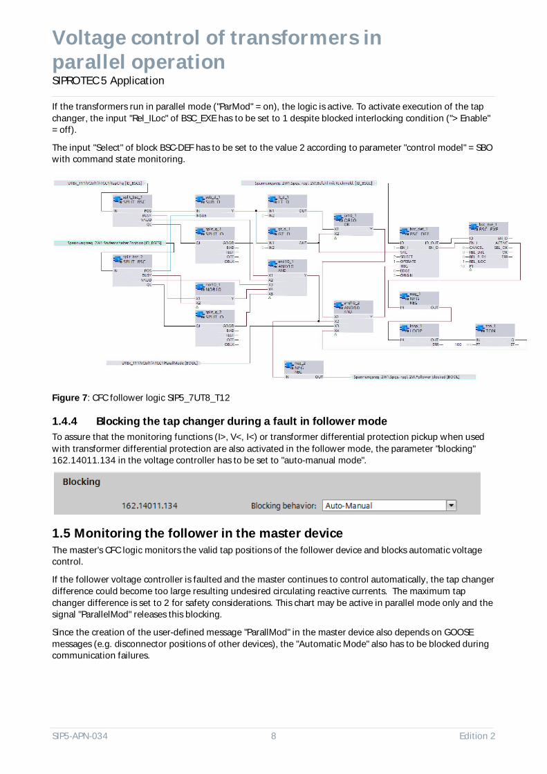
If the transformers run in parallel mode ("ParMod" = on), the logic is active. To activate execution of the tapchanger, the input "Rel_ILoc" of BSC_EXE has to be set to 1 despite blocked interlocking condition ("> Enable"= off).
The input "Select" of block BSC-DEF has to be set to the value 2 according to parameter "control model" = SBOwith command state monitoring.
Figure 7: CFC follower logic SIP5_7UT8_T12
1.4.4 Blocking the tap changer during a fault in follower modeTo assure that the monitoring functions (I>, V<, I<) or transformer differential protection pickup when usedwith transformer differential protection are also activated in the follower mode, the parameter "blocking"162.14011.134 in the voltage controller has to be set to "auto-manual mode".
1.5 Monitoring the follower in the master deviceThe master's CFC logic monitors the valid tap positions of the follower device and blocks automatic voltagecontrol.
If the follower voltage controller is faulted and the master continues to control automatically, the tap changerdifference could become too large resulting undesired circulating reactive currents. The maximum tapchanger difference is set to 2 for safety considerations. This chart may be active in parallel mode only and thesignal "ParallelMod" releases this blocking.
Since the creation of the user-defined message "ParallMod" in the master device also depends on GOOSEmessages (e.g. disconnector positions of other devices), the "Automatic Mode" also has to be blocked duringcommunication failures.

Voltage control for transformers in paralleloperation
SIPROTEC 5 Application
Edition 2 9 SIP5-APN-034
Figure 8: Master CFC chart logic, example of ParallelMod creation
Figure 9: Principle of the CFC logic in the master device SIP5_7UT8_T11

Voltage control of transformers inparallel operationSIPROTEC 5 Application
SIP5-APN-034 10 Edition 2
Figure 10: CFC logic in the master device SIP5_7UT8_T12
In the CFC example above, the IEC 61850 object "ParOP" in ATCC is not set by the master operation. Instead,the user-defined message "ParallMod" has to be used or transmitted to the control system.
1.6 IEC 61850 GOOSE communicationThe GOOSE messages between the two devices are set in the IEC 61850 System Configurator:
First, the FC/DA mapping has to be adjusted for the BSC control objects "TapChg" in the source objects and thevalWTr.transInd has to be added.Properties -> Parameters -> Open drop-down box.
Voltage control for transformers in paralleloperation
SIPROTEC 5 Application
Edition 2 11 SIP5-APN-034
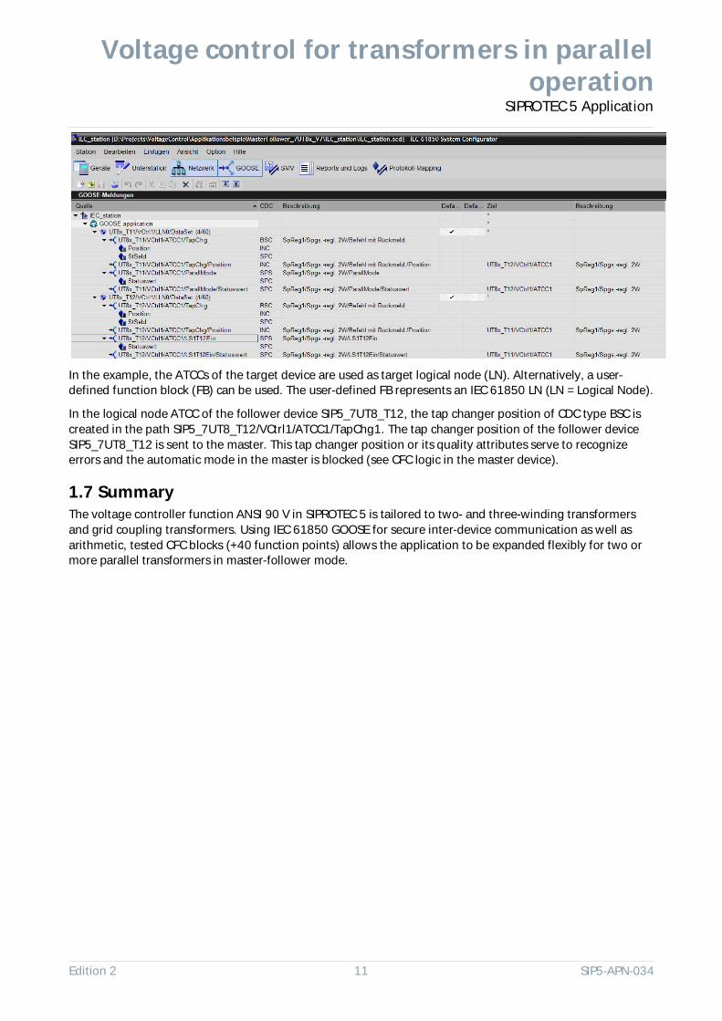
In the example, the ATCCs of the target device are used as target logical node (LN). Alternatively, a user-defined function block (FB) can be used. The user-defined FB represents an IEC 61850 LN (LN = Logical Node).
In the logical node ATCC of the follower device SIP5_7UT8_T12, the tap changer position of CDC type BSC iscreated in the path SIP5_7UT8_T12/VCtrl1/ATCC1/TapChg1. The tap changer position of the follower deviceSIP5_7UT8_T12 is sent to the master. This tap changer position or its quality attributes serve to recognizeerrors and the automatic mode in the master is blocked (see CFC logic in the master device).
1.7 SummaryThe voltage controller function ANSI 90 V in SIPROTEC 5 is tailored to two- and three-winding transformersand grid coupling transformers. Using IEC 61850 GOOSE for secure inter-device communication as well asarithmetic, tested CFC blocks (+40 function points) allows the application to be expanded flexibly for two ormore parallel transformers in master-follower mode.

SIPROTEC 5 ApplicationError! Reference source not found.
SIP5-APN-034 12 Edition 2
Publisher and copyright © 2016:
Siemens AGEnergy ManagementProductsHumboldtstr. 5990459 Nürnberg, Deutschlandwww.siemens.com/siprotec
For more information, please contact your Siemenssales contact or our Customer Support Center.
Phone: +49 180 524 84 37Fax: +49 180 524 24 71(costs depending on provider)E-mail: [email protected]
Application: SIP5-APN-034, Edition 2
Printed on paper produced without chlorine bleaching.
All rights reserved. The trademarks and brandsmentioned in this document are the property of SiemensAG or its holdings or of the respective holders. Subject tochange without notice.
The information in this document contain generaldescriptions of the technically possibilities which may notbe available in the individual case. The desiredperformance characteristics must therefore be specifiedupon signing the contract.
The following applies to all products that contain ITsecurity functions of OpenSSL:
This product includes software developed by theOpenSSL Project for use in the OpenSSL Toolkit(www.openssl.org).
This product includes cryptographic software writtenby Eric Young ([email protected]).