single-sided formwork smk
TRANSCRIPT
User Guide
Single-sided FormworkSMK
00FIL14
IMPORTANT: Any safety provisions as directed by the appropriate governing agencies must be observed when using our products. The pictures in this document are snapshots of situations at different stages of assembly, and therefore are not complete images. For the purpose of safety, they should not be deemed as definitive. All instructions regarding safety and operations contained in this document, and the data on stress and loads must be respected. ULMA Construcción’s Technical Department must be consulted any time that field changes alter our equipment installation drawings. The loads featured in this document, related to the basic parts of the product, are approximate. Our equipment is designed to work with accessories and parts produced by our company only. Combining such equipment with other brands is not only dangerous without having made all corresponding verifications, it also voids any or all our warranties. The company reserves the right to introduce any modifications deemed necessary for the technical development of the product.
“Original document” produced and approved by ULMA Construcción. All rights reserved. Neither the whole nor any part of this document may be reproduced or transmitted in any form or by any means (electronic or mechanical), including photocopy, recording or any other form of information storage or retrieval system without the permission of ULMA Construcción. © Copyright by ULMA C y E, S. Coop
Information note
Safety note
Warning note
Control note
3
TABLE OF CONTENTS
1. PRODUCT DESCRIPTION ................................................................................................................................. 4
2. SYSTEM COMPONENTS AND ACCESSORIES .................................................................................................... 6
2.1. GRAPHIC DESCRIPTION ............................................................................................................................................ 6
2.2. ITEMS DESCRIPTION .............................................................................................................................................. 11
3. ASSEMBLY AND USE ................................................................................................................................... 19
3.1. SMK FRAME STRUCTURE ....................................................................................................................................... 19
3.2. FRAMES ASSEMBLY ON THE FORMWORK PANELS ................................................................................................ 22
3.3. ASSEMBLY BRACING TUBES .................................................................................................................................. 26
3.4. ASSEMBLY LIFTING HOOK MK ............................................................................................................................... 28
4. SOLUTIONS ................................................................................................................................................. 30
4.1. WALLS UP TO 3M .................................................................................................................................................. 30
4.2. WALLS UP TO 3,40M ............................................................................................................................................. 33
4.3. WALLS UP TO 5,40M ............................................................................................................................................. 34
4.4. WALLS UP TO 6,60M ............................................................................................................................................. 38
4.5. WALLS UP TO 8,70M ............................................................................................................................................. 42
4.6. WALLS UP TO 10,50M ........................................................................................................................................... 47
4.7. ANCHORAGE SYSTEM ........................................................................................................................................... 50
5. SYSTEM FEATURES ...................................................................................................................................... 59
5.1. Load Tables - MODULAR FORMWORK ................................................................................................................... 59
5.2. Load Tables - MODULAR FORMWORK + HORIZONTAL WALER ............................................................................. 63
5.3. Load Tables - ENKOFORM FORMWORK. ................................................................................................................ 69
6. CONDITIONS OF USE ................................................................................................................................... 73
6.1. GENERAL CONDITIONS OF USE: ............................................................................................................................ 73
7. LEGAL REFERENCES ..................................................................................................................................... 76
8. APPENDICES ............................................................................................................................................... 77
8.1. MATERIAL LIST ...................................................................................................................................................... 77
8.2. DECLARATION OF CONFORMITY : LIFTING HOOK MK ............................................................................................ 83
4
SMK
1. PRODUCT DESCRIPTION
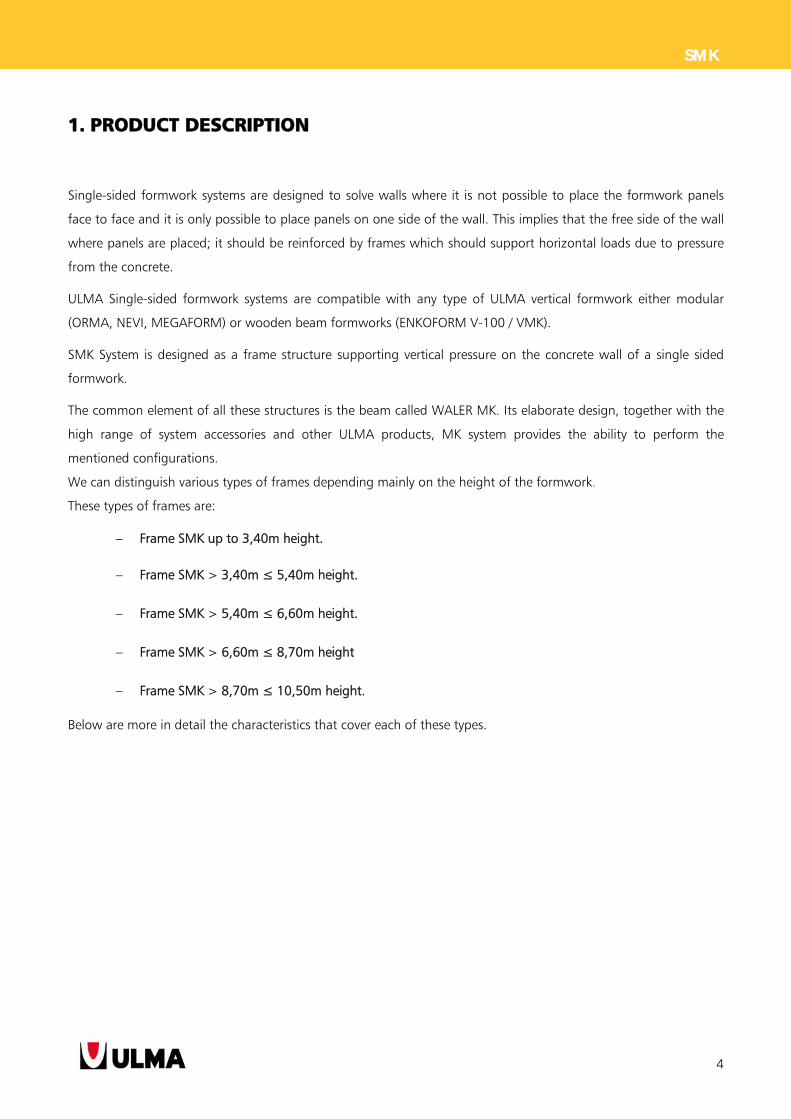
Single-sided formwork systems are designed to solve walls where it is not possible to place the formwork panels
face to face and it is only possible to place panels on one side of the wall. This implies that the free side of the wall
where panels are placed; it should be reinforced by frames which should support horizontal loads due to pressure
from the concrete.
ULMA Single-sided formwork systems are compatible with any type of ULMA vertical formwork either modular
(ORMA, NEVI, MEGAFORM) or wooden beam formworks (ENKOFORM V-100 / VMK).
SMK System is designed as a frame structure supporting vertical pressure on the concrete wall of a single sided
formwork.
The common element of all these structures is the beam called WALER MK. Its elaborate design, together with the
high range of system accessories and other ULMA products, MK system provides the ability to perform the
mentioned configurations.
We can distinguish various types of frames depending mainly on the height of the formwork.
These types of frames are:
Frame SMK up to 3,40m height.
Frame SMK > 3,40m ≤ 5,40m height.
Frame SMK > 5,40m ≤ 6,60m height.
Frame SMK > 6,60m ≤ 8,70m height
Frame SMK > 8,70m ≤ 10,50m height.
Below are more in detail the characteristics that cover each of these types.
5
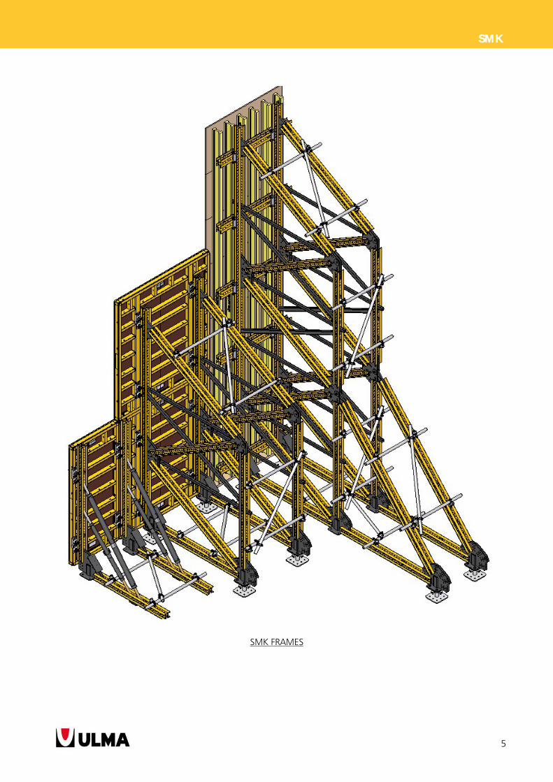
SMK
SMK FRAMES
6
SMK
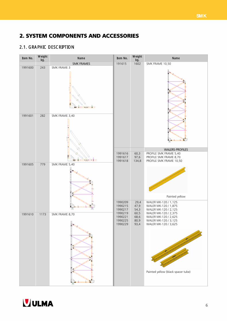
2. SYSTEM COMPONENTS AND ACCESSORIES
2.1. GRAPHIC DESCRIPTION
Item No. Weight
kg. Name
SMK FRAMES 1991600 243 SMK FRAME 3
1991601 282 SMK FRAME 3,40
1991605 779 SMK FRAME 5,40
1991610 1173 SMK FRAME 8,70
Item No. Weight
kg. Name
191615 1602 SMK FRAME 10,50
WALERS-PROFILES 1991616 1991617 1991618
60,3 97,6
134,8
PROFILE SMK FRAME 5,40 PROFILE SMK FRAME 8,70 PROFILE SMK FRAME 10,50
Painted yellow 1990209 1990215 1990217 1990219 1990221 1990225 1990229
29,4 47,9 54,3 60,5 68,6 80,9 93,4
WALER MK-120 / 1,125 WALER MK-120 / 1,875 WALER MK-120 / 2,125 WALER MK-120 / 2,375 WALER MK-120 / 2,625 WALER MK-120 / 3,125 WALER MK-120 / 3,625
Painted yellow (black spacer tube)
7
SMK
Item No. Weight
kg. Name
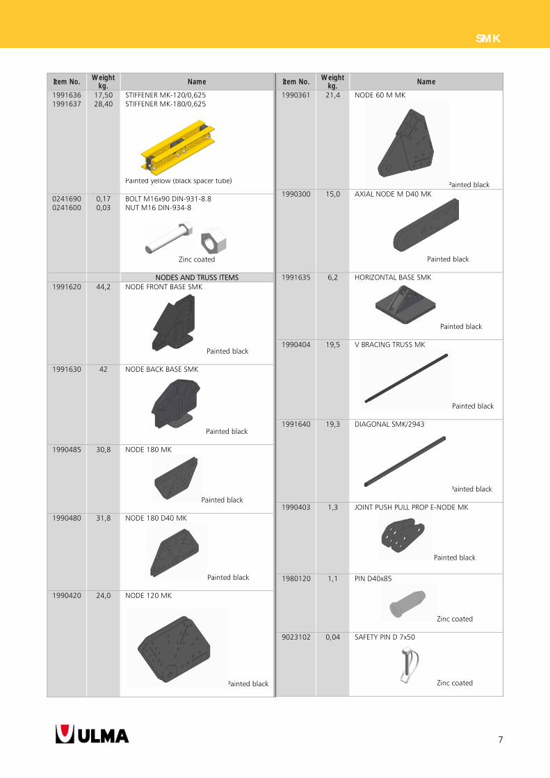
1991636 1991637
17,50 28,40
STIFFENER MK-120/0,625 STIFFENER MK-180/0,625
Painted yellow (black spacer tube)
0241690 0241600
0,17 0,03
BOLT M16x90 DIN-931-8.8 NUT M16 DIN-934-8
Zinc coated
NODES AND TRUSS ITEMS 1991620 44,2 NODE FRONT BASE SMK
Painted black
1991630 42 NODE BACK BASE SMK
Painted black
1990485 30,8 NODE 180 MK
Painted black
1990480 31,8 NODE 180 D40 MK
Painted black
1990420 24,0 NODE 120 MK
Painted black
Item No. Weight
kg. Name
1990361 21,4 NODE 60 M MK
Painted black 1990300
15,0
AXIAL NODE M D40 MK
Painted black
1991635 6,2 HORIZONTAL BASE SMK
Painted black
1990404 19,5 V BRACING TRUSS MK
Painted black
1991640
19,3
DIAGONAL SMK/2943
Painted black
1990403 1,3 JOINT PUSH PULL PROP E-NODE MK
Painted black
1980120 1,1 PIN D40x85
Zinc coated
9023102 0,04 SAFETY PIN D 7x50
Zinc coated
8
SMK
Item No. Weight
kg. Name
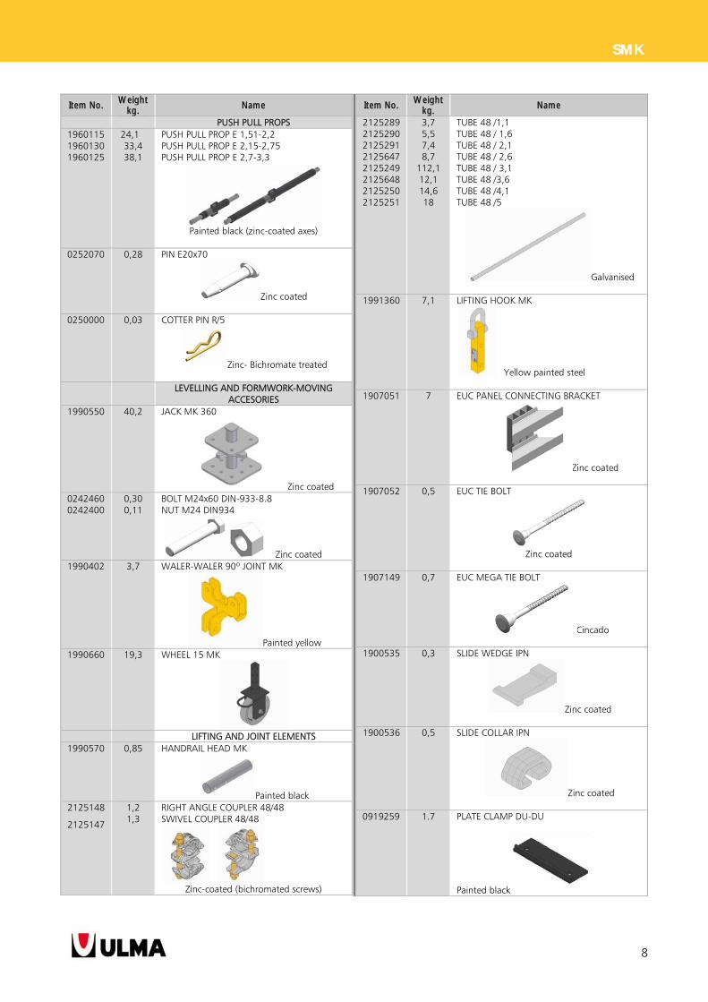
PUSH PULL PROPS 1960115 1960130 1960125
24,1 33,4 38,1
PUSH PULL PROP E 1,51-2,2 PUSH PULL PROP E 2,15-2,75 PUSH PULL PROP E 2,7-3,3
Painted black (zinc-coated axes)
0252070 0,28 PIN E20x70
Zinc coated
0250000 0,03 COTTER PIN R/5
Zinc- Bichromate treated
LEVELLING AND FORMWORK-MOVING ACCESORIES
1990550 40,2 JACK MK 360
Zinc coated 0242460 0242400
0,30 0,11
BOLT M24x60 DIN-933-8.8 NUT M24 DIN934
Zinc coated 1990402 3,7 WALER-WALER 90º JOINT MK
Painted yellow 1990660 19,3 WHEEL 15 MK
LIFTING AND JOINT ELEMENTS 1990570 0,85 HANDRAIL HEAD MK
Painted black 2125148
2125147
1,2 1,3
RIGHT ANGLE COUPLER 48/48 SWIVEL COUPLER 48/48
Zinc-coated (bichromated screws)
Item No. Weight
kg. Name
2125289 2125290 2125291 2125647 2125249 2125648 2125250 2125251
3,7 5,5 7,4 8,7
112,1 12,1 14,6 18
TUBE 48 /1,1 TUBE 48 / 1,6 TUBE 48 / 2,1 TUBE 48 / 2,6 TUBE 48 / 3,1 TUBE 48 /3,6 TUBE 48 /4,1 TUBE 48 /5
Galvanised
1991360 7,1 LIFTING HOOK MK
Yellow painted steel
1907051 7 EUC PANEL CONNECTING BRACKET
Zinc coated
1907052 0,5 EUC TIE BOLT
Zinc coated
1907149 0,7 EUC MEGA TIE BOLT
Cincado
1900535 0,3 SLIDE WEDGE IPN
Zinc coated
1900536 0,5 SLIDE COLLAR IPN
Zinc coated
0919259 1.7 PLATE CLAMP DU-DU
Painted black
9
SMK
Item No. Weight
kg. Name
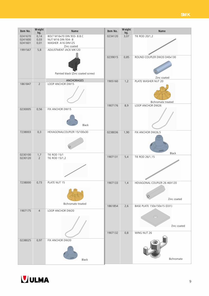
0241670 0241600 0241601
0,14 0,03 0,01
BOLT M16x70 DIN 933- 8.8.C NUT M16 DIN 934- 8 WASHER A16 DIN125 Zinc coated
1991567 5,8 ADJUSTMENT JACK MK120
Painted black (Zinc coated screw)
ANCHORAGES 1861847 2 LOOP ANCHOR DW15
0230005 0,56 FIX ANCHOR DW15
Black
7238003 0,3 HEXAGONALCOUPLER 15/100x30
0230100 0230120
1,7 2
TIE ROD 15/1 TIE ROD 15/1,2
7238000 0,73 PLATE NUT 15
Bichromate treated
1907175 4 LOOP ANCHOR DW20
0238025 0,97 FIX ANCHOR DW20
Black
Item No. Weight
kg. Name
0234120 3,07 TIE ROD 20/1,2
0239015 0,85 ROUND COUPLER DW20 D40x130
Zinc coated
1905160 1,2 PLATE WASHER NUT 20
Bichromate treated
1907176 8,9 LOOP ANCHOR DW26
0238036 1,90 FIX ANCHOR DW26,5
Black 1907131 5,4 TIE ROD 26/1,15
1907133 1,4 HEXAGONAL COUPLER 26 46X120
Zinc coated
1861854 2,6 BASE PLATE 150x150x15 (D31)
Zinc coated
1907132 0,8 WING NUT 26
Bichromate
10
SMK
Item No. Weight
kg. Name
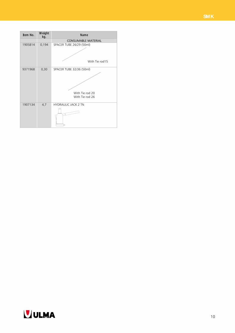
CONSUMABLE MATERIAL 1905814 0,194 SPACER TUBE 26/29 (50ml)
With Tie rod15
9371968 0,30 SPACER TUBE 32/36 (50ml)
With Tie rod 20 With Tie rod 26
1907134 4,7 HYDRAULIC JACK 2 TN
11
SMK
2.2. ITEMS DESCRIPTION
The following connections with bolt and nut will
be shortly describes as M16, M20 and M24 in this
document, meaning:
- M16: Bolt M16 DIN 931-8.8 + Nut M16
DIN 934-8
- M20: Bolt M20 DIN 931-8.8 + Nut M20
DIN 934-8
- M24. Bolt M24 DIN 931-8.8 + Nut M24 DIN
934-8 + 2 Washers 24 DIN125
2.2.1. SMK FRAME 3
A frame structure formed by horizontal waler MK-
120 and other vertical waler MK-120 connected both
by M16 bolts to the NODE FRONT BASE SMK and
besides two push pull props E.
It also has a horizontal base SMK above ground and
handrails heads MK to brace them
Valid for supporting formwork heights up to 3
meters.
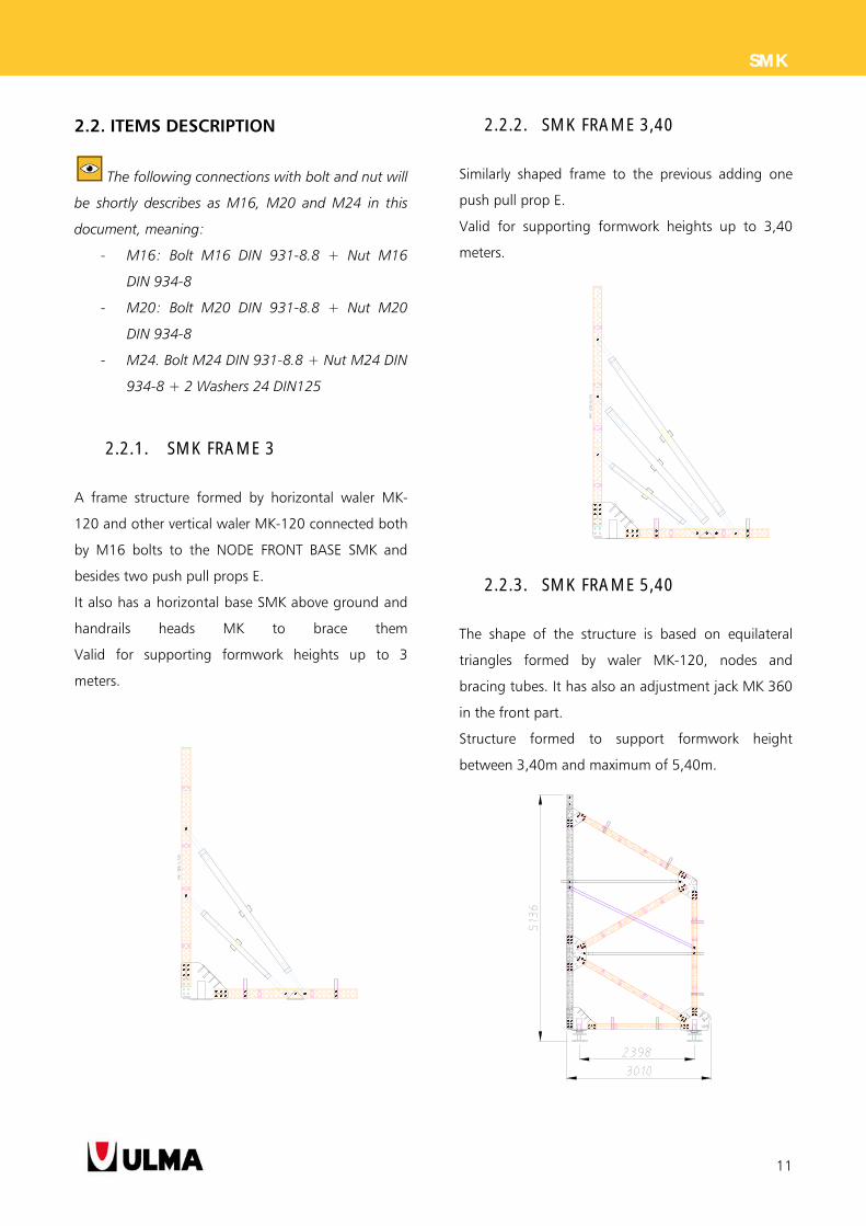
2.2.2. SMK FRAME 3,40
Similarly shaped frame to the previous adding one
push pull prop E.
Valid for supporting formwork heights up to 3,40
meters.
2.2.3. SMK FRAME 5,40
The shape of the structure is based on equilateral
triangles formed by waler MK-120, nodes and
bracing tubes. It has also an adjustment jack MK 360
in the front part.
Structure formed to support formwork height
between 3,40m and maximum of 5,40m.
12
SMK
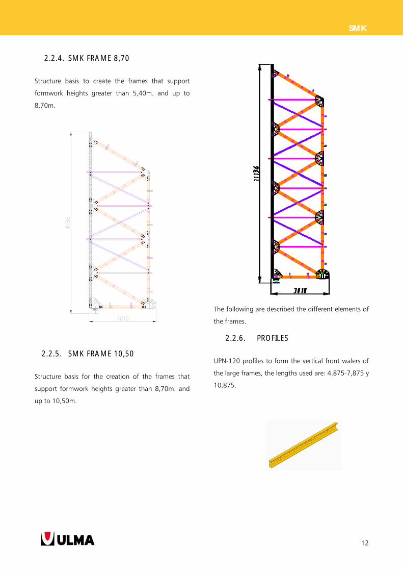
2.2.4. SMK FRAME 8,70
Structure basis to create the frames that support
formwork heights greater than 5,40m. and up to
8,70m.
2.2.5. SMK FRAME 10,50
Structure basis for the creation of the frames that
support formwork heights greater than 8,70m. and
up to 10,50m.
The following are described the different elements of
the frames.
2.2.6. PROFILES
UPN-120 profiles to form the vertical front walers of
the large frames, the lengths used are: 4,875-7,875 y
10,875.
13
SMK
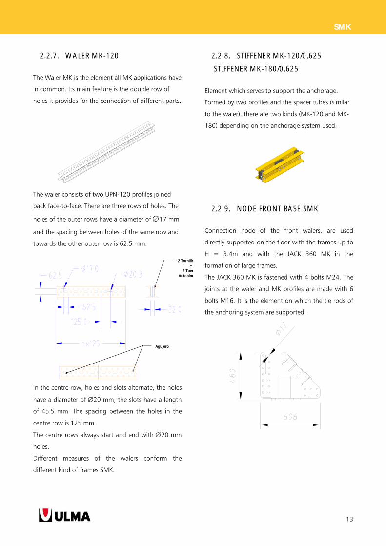
2.2.7. WALER MK-120
The Waler MK is the element all MK applications have
in common. Its main feature is the double row of
holes it provides for the connection of different parts.
The waler consists of two UPN-120 profiles joined
back face-to-face. There are three rows of holes. The
holes of the outer rows have a diameter of 17 mm
and the spacing between holes of the same row and
towards the other outer row is 62.5 mm.
In the centre row, holes and slots alternate, the holes
have a diameter of 20 mm, the slots have a length
of 45.5 mm. The spacing between the holes in the
centre row is 125 mm.
The centre rows always start and end with 20 mm
holes.
Different measures of the walers conform the
different kind of frames SMK.
2.2.8. STIFFENER MK-120/0,625
STIFFENER MK-180/0,625
Element which serves to support the anchorage.
Formed by two profiles and the spacer tubes (similar
to the waler), there are two kinds (MK-120 and MK-
180) depending on the anchorage system used.
2.2.9. NODE FRONT BASE SMK
Connection node of the front walers, are used
directly supported on the floor with the frames up to
H = 3.4m and with the JACK 360 MK in the
formation of large frames.
The JACK 360 MK is fastened with 4 bolts M24. The
joints at the waler and MK profiles are made with 6
bolts M16. It is the element on which the tie rods of
the anchoring system are supported.
2 Tornillo+
2 TuerAutobloc
Agujero
14
SMK
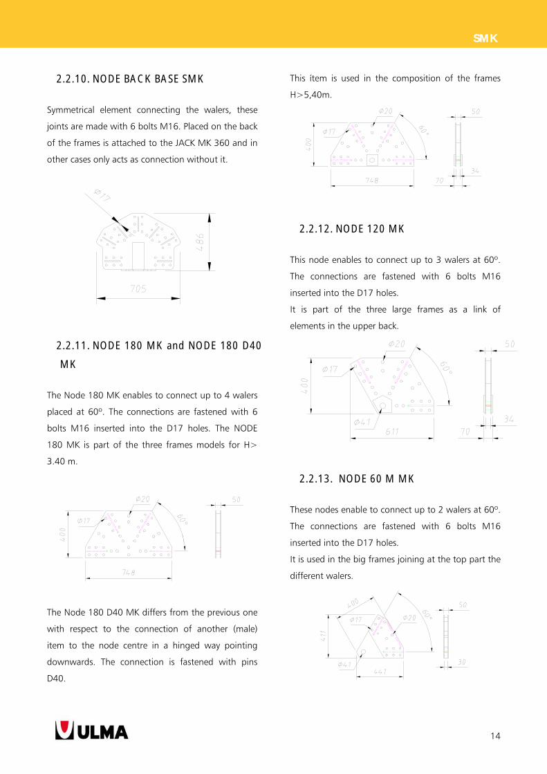
2.2.10. NODE BACK BASE SMK
Symmetrical element connecting the walers, these
joints are made with 6 bolts M16. Placed on the back
of the frames is attached to the JACK MK 360 and in
other cases only acts as connection without it.
2.2.11. NODE 180 MK and NODE 180 D40
MK
The Node 180 MK enables to connect up to 4 walers
placed at 60º. The connections are fastened with 6
bolts M16 inserted into the D17 holes. The NODE
180 MK is part of the three frames models for H>
3.40 m.
The Node 180 D40 MK differs from the previous one
with respect to the connection of another (male)
item to the node centre in a hinged way pointing
downwards. The connection is fastened with pins
D40.
This ítem is used in the composition of the frames
H>5,40m.
2.2.12. NODE 120 MK
This node enables to connect up to 3 walers at 60º.
The connections are fastened with 6 bolts M16
inserted into the D17 holes.
It is part of the three large frames as a link of
elements in the upper back.
2.2.13. NODE 60 M MK
These nodes enable to connect up to 2 walers at 60º.
The connections are fastened with 6 bolts M16
inserted into the D17 holes.
It is used in the big frames joining at the top part the
different walers.
15
SMK
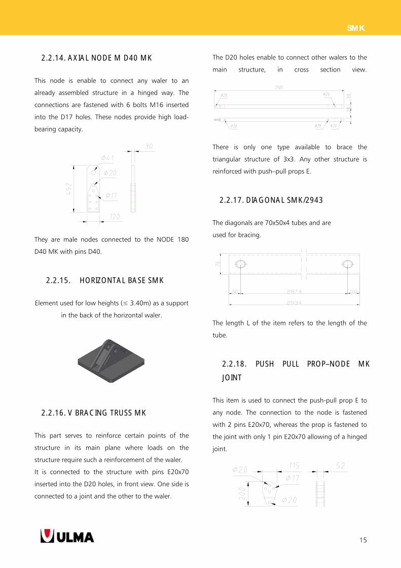
2.2.14. AXIAL NODE M D40 MK
This node is enable to connect any waler to an
already assembled structure in a hinged way. The
connections are fastened with 6 bolts M16 inserted
into the D17 holes. These nodes provide high load-
bearing capacity.
They are male nodes connected to the NODE 180
D40 MK with pins D40.
2.2.15. HORIZONTAL BASE SMK
Element used for low heights (≤ 3.40m) as a support
in the back of the horizontal waler.
2.2.16. V BRACING TRUSS MK
This part serves to reinforce certain points of the
structure in its main plane where loads on the
structure require such a reinforcement of the waler.
It is connected to the structure with pins E20x70
inserted into the D20 holes, in front view. One side is
connected to a joint and the other to the waler.
The D20 holes enable to connect other walers to the
main structure, in cross section view.
There is only one type available to brace the
triangular structure of 3x3. Any other structure is
reinforced with push–pull props E.
2.2.17. DIAGONAL SMK/2943
The diagonals are 70x50x4 tubes and are
used for bracing.
The length L of the item refers to the length of the
tube.
2.2.18. PUSH PULL PROP–NODE MK
JOINT
This item is used to connect the push-pull prop E to
any node. The connection to the node is fastened
with 2 pins E20x70, whereas the prop is fastened to
the joint with only 1 pin E20x70 allowing of a hinged
joint.
16
SMK
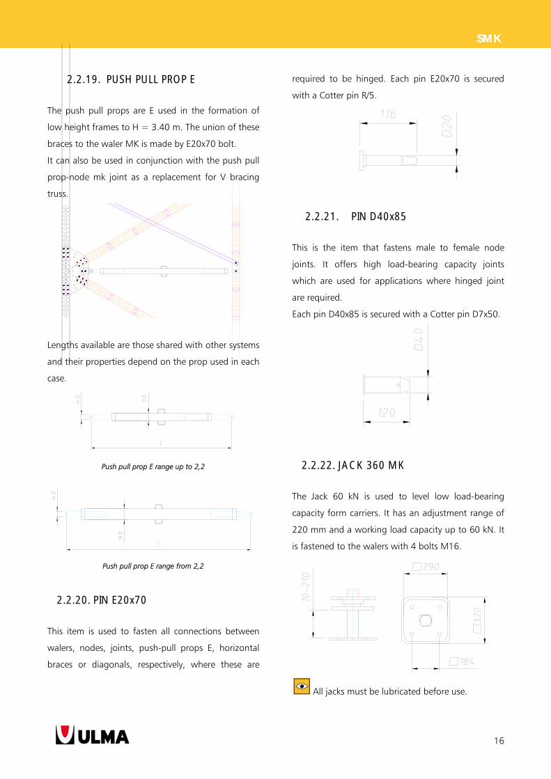
2.2.19. PUSH PULL PROP E
The push pull props are E used in the formation of
low height frames to H = 3.40 m. The union of these
braces to the waler MK is made by E20x70 bolt.
It can also be used in conjunction with the push pull
prop-node mk joint as a replacement for V bracing
truss.
Lengths available are those shared with other systems
and their properties depend on the prop used in each
case.
Push pull prop E range up to 2,2
Push pull prop E range from 2,2
2.2.20. PIN E20x70
This item is used to fasten all connections between
walers, nodes, joints, push-pull props E, horizontal
braces or diagonals, respectively, where these are
required to be hinged. Each pin E20x70 is secured
with a Cotter pin R/5.
2.2.21. PIN D40x85
This is the item that fastens male to female node
joints. It offers high load-bearing capacity joints
which are used for applications where hinged joint
are required.
Each pin D40x85 is secured with a Cotter pin D7x50.
2.2.22. JACK 360 MK
The Jack 60 kN is used to level low load-bearing
capacity form carriers. It has an adjustment range of
220 mm and a working load capacity up to 60 kN. It
is fastened to the walers with 4 bolts M16.
All jacks must be lubricated before use.
17
SMK
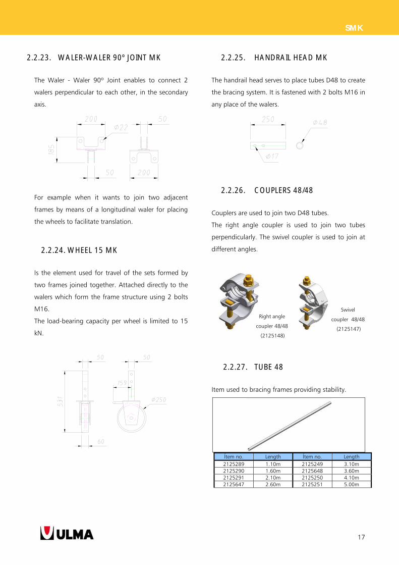
2.2.23. WALER-WALER 90º JOINT MK
The Waler - Waler 90º Joint enables to connect 2
walers perpendicular to each other, in the secondary
axis.
For example when it wants to join two adjacent
frames by means of a longitudinal waler for placing
the wheels to facilitate translation.
2.2.24. WHEEL 15 MK
Is the element used for travel of the sets formed by
two frames joined together. Attached directly to the
walers which form the frame structure using 2 bolts
M16.
The load-bearing capacity per wheel is limited to 15
kN.
2.2.25. HANDRAIL HEAD MK
The handrail head serves to place tubes D48 to create
the bracing system. It is fastened with 2 bolts M16 in
any place of the walers.
2.2.26. COUPLERS 48/48
Couplers are used to join two D48 tubes.
The right angle coupler is used to join two tubes
perpendicularly. The swivel coupler is used to join at
different angles.
2.2.27. TUBE 48
Item used to bracing frames providing stability.
Ítem no. Length Ítem no. Length 2125289 1.10m 2125249 3.10m 2125290 1.60m 2125648 3.60m 2125291 2.10m 2125250 4.10m 2125647 2.60m 2125251 5.00m
Right angle
coupler 48/48
(2125148)
Swivel
coupler 48/48
(2125147)
18
SMK
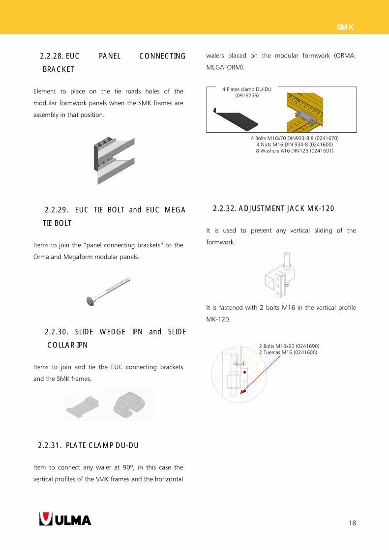
2.2.28. EUC PANEL CONNECTING
BRACKET
Element to place on the tie roads holes of the
modular formwork panels when the SMK frames are
assembly in that position.
2.2.29. EUC TIE BOLT and EUC MEGA
TIE BOLT
Items to join the “panel connecting brackets” to the
Orma and Megaform modular panels.
2.2.30. SLIDE WEDGE IPN and SLIDE
COLLAR IPN
Items to join and tie the EUC connecting brackets
and the SMK frames.
2.2.31. PLATE CLAMP DU-DU
Item to connect any waler at 90º, in this case the
vertical profiles of the SMK frames and the horizontal
walers placed on the modular formwork (ORMA,
MEGAFORM).
2.2.32. ADJUSTMENT JACK MK-120
It is used to prevent any vertical sliding of the
formwork.
It is fastened with 2 bolts M16 in the vertical profile
MK-120.
4 Plates clamp DU-DU (0919259)
4 Bolts M16x70 DIN933-8.8 (0241670) 4 Nuts M16 DIN 934-8 (0241600) 8 Washers A16 DIN125 (0241601)
2 Bolts M16x90 (0241690) 2 Tuercas M16 (0241600)
19
SMK
3. ASSEMBLY AND USE
The assemblies can be distinguished by:
Mounting the SMK frame structure.
Assembling the SMK frame on the formwork panel.
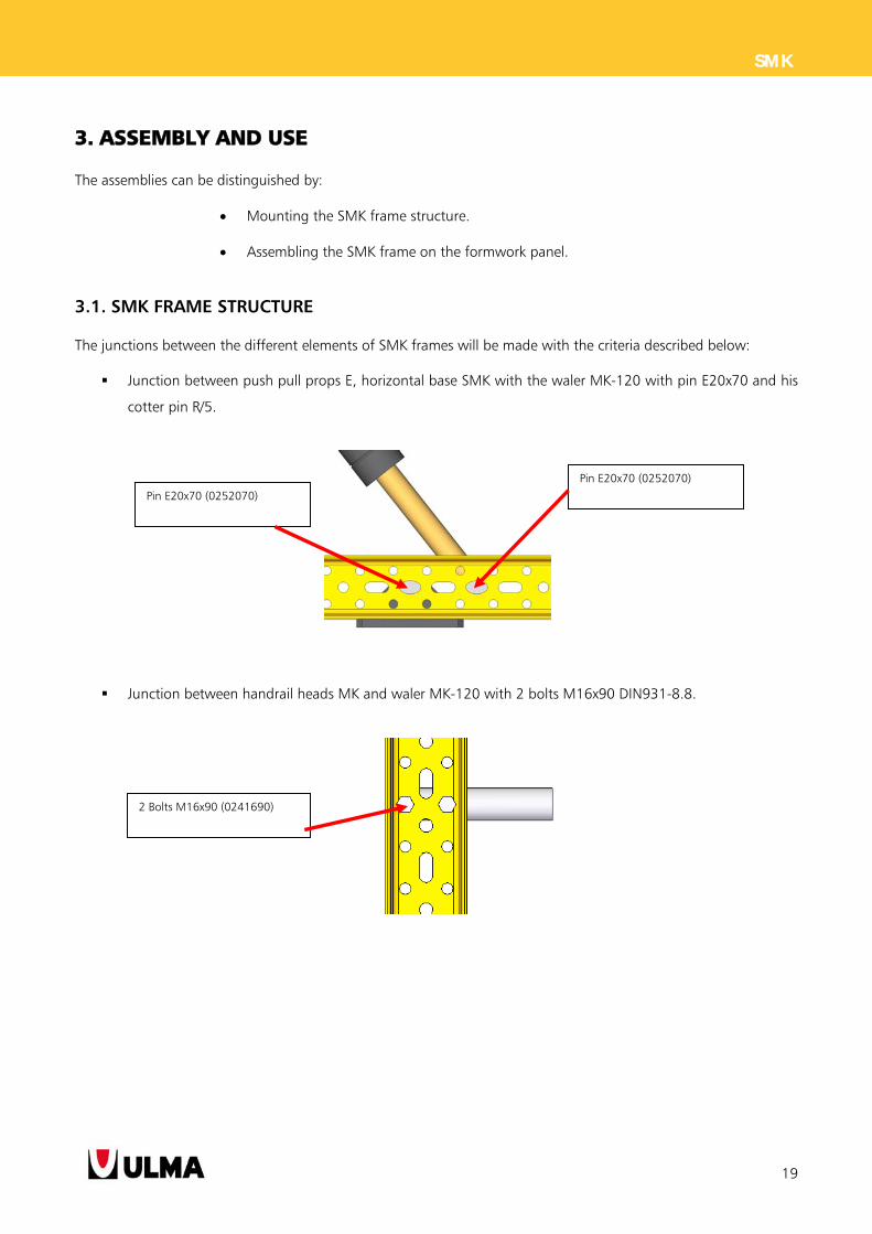
3.1. SMK FRAME STRUCTURE
The junctions between the different elements of SMK frames will be made with the criteria described below:
Junction between push pull props E, horizontal base SMK with the waler MK-120 with pin E20x70 and his
cotter pin R/5.
Junction between handrail heads MK and waler MK-120 with 2 bolts M16x90 DIN931-8.8.
Pin E20x70 (0252070)
Pin E20x70 (0252070)
2 Bolts M16x90 (0241690)
20
SMK
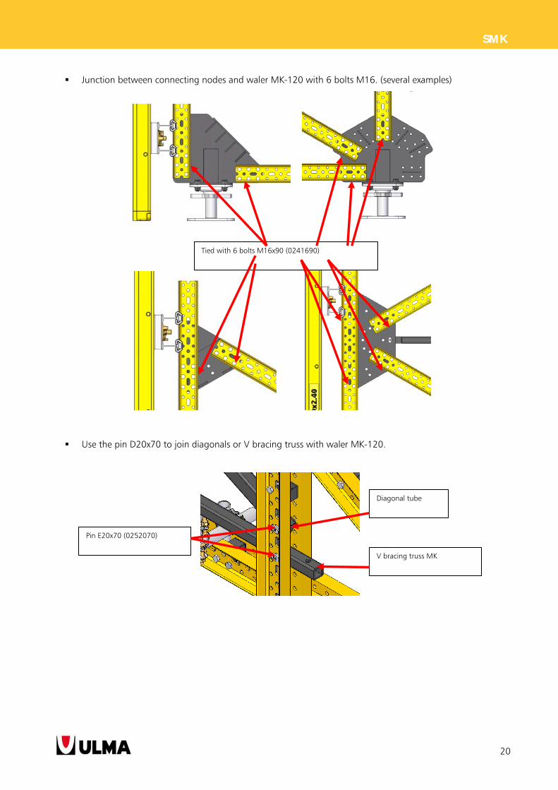
Junction between connecting nodes and waler MK-120 with 6 bolts M16. (several examples)
Use the pin D20x70 to join diagonals or V bracing truss with waler MK-120.
Tied with 6 bolts M16x90 (0241690)
Pin E20x70 (0252070)
Diagonal tube
V bracing truss MK
21
SMK
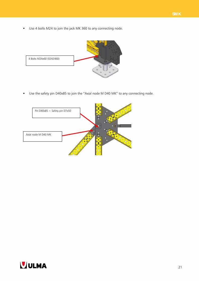
Use 4 bolts M24 to join the jack MK 360 to any connecting node.
Use the safety pin D40x85 to join the “Axial node M D40 MK” to any connecting node.
4 Bolts M24x60 (0242460)
Axial node M D40 MK
Pin D40x85 + Safety pin D7x50
22
SMK
3.2. FRAMES ASSEMBLY ON THE FORMWORK PANELS
The union of the frames to the formwork depends on the type of panel used:
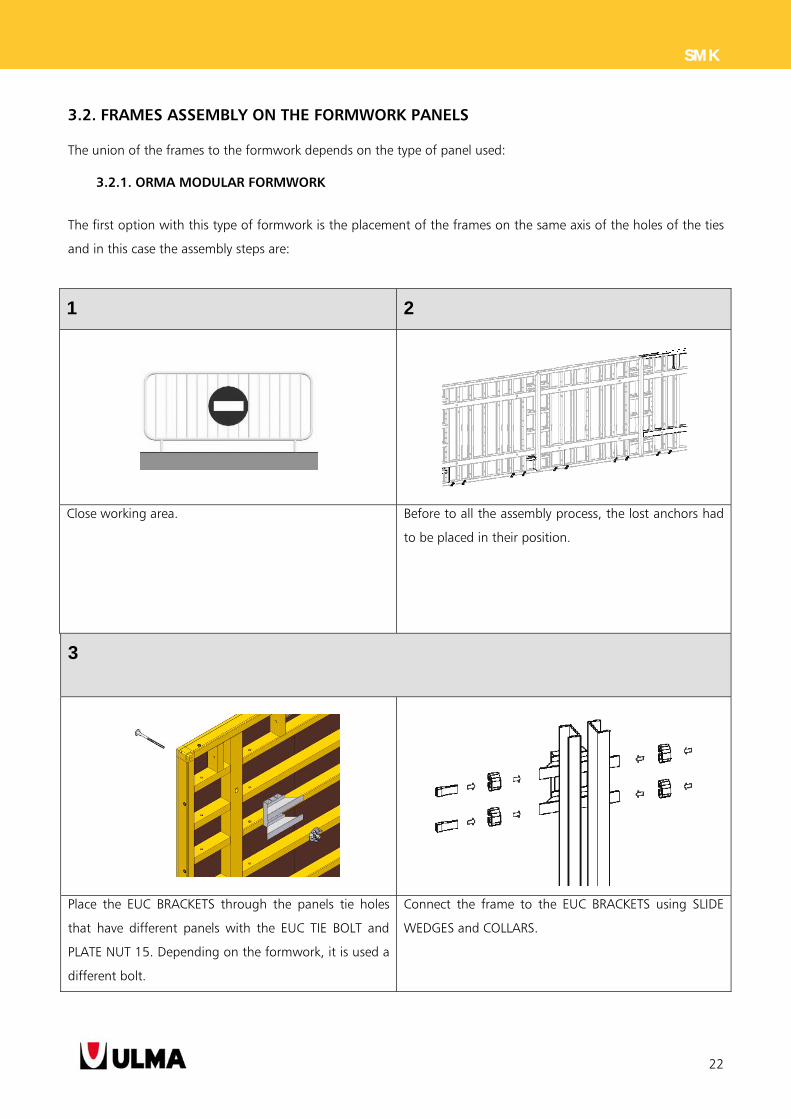
3.2.1. ORMA MODULAR FORMWORK
The first option with this type of formwork is the placement of the frames on the same axis of the holes of the ties
and in this case the assembly steps are:
1 2
Close working area. Before to all the assembly process, the lost anchors had
to be placed in their position.
3
Place the EUC BRACKETS through the panels tie holes
that have different panels with the EUC TIE BOLT and
PLATE NUT 15. Depending on the formwork, it is used a
different bolt.
Connect the frame to the EUC BRACKETS using SLIDE
WEDGES and COLLARS.
23
SMK
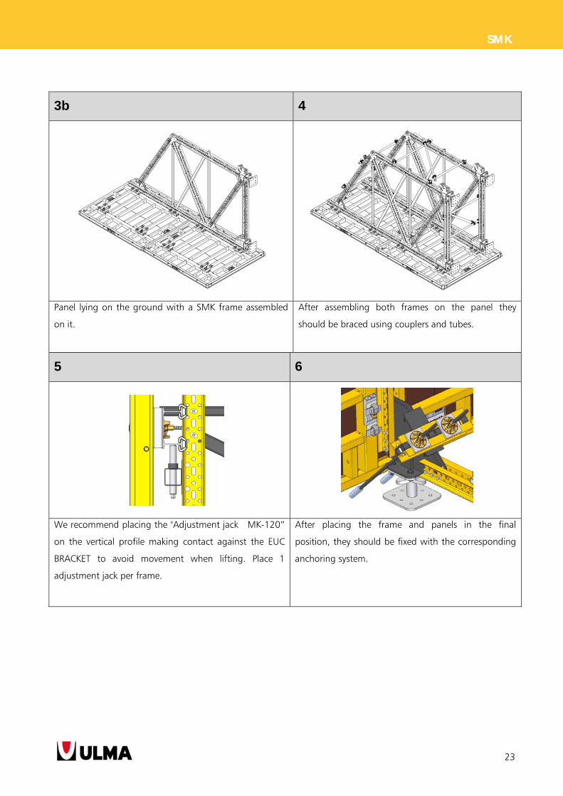
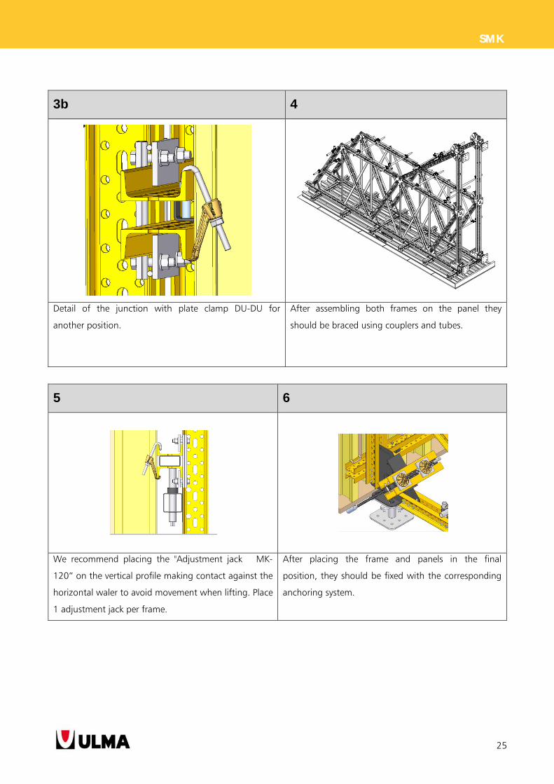
3b 4
Panel lying on the ground with a SMK frame assembled
on it.
After assembling both frames on the panel they
should be braced using couplers and tubes.
5 6
We recommend placing the "Adjustment jack MK-120”
on the vertical profile making contact against the EUC
BRACKET to avoid movement when lifting. Place 1
adjustment jack per frame.
After placing the frame and panels in the final
position, they should be fixed with the corresponding
anchoring system.
24
SMK
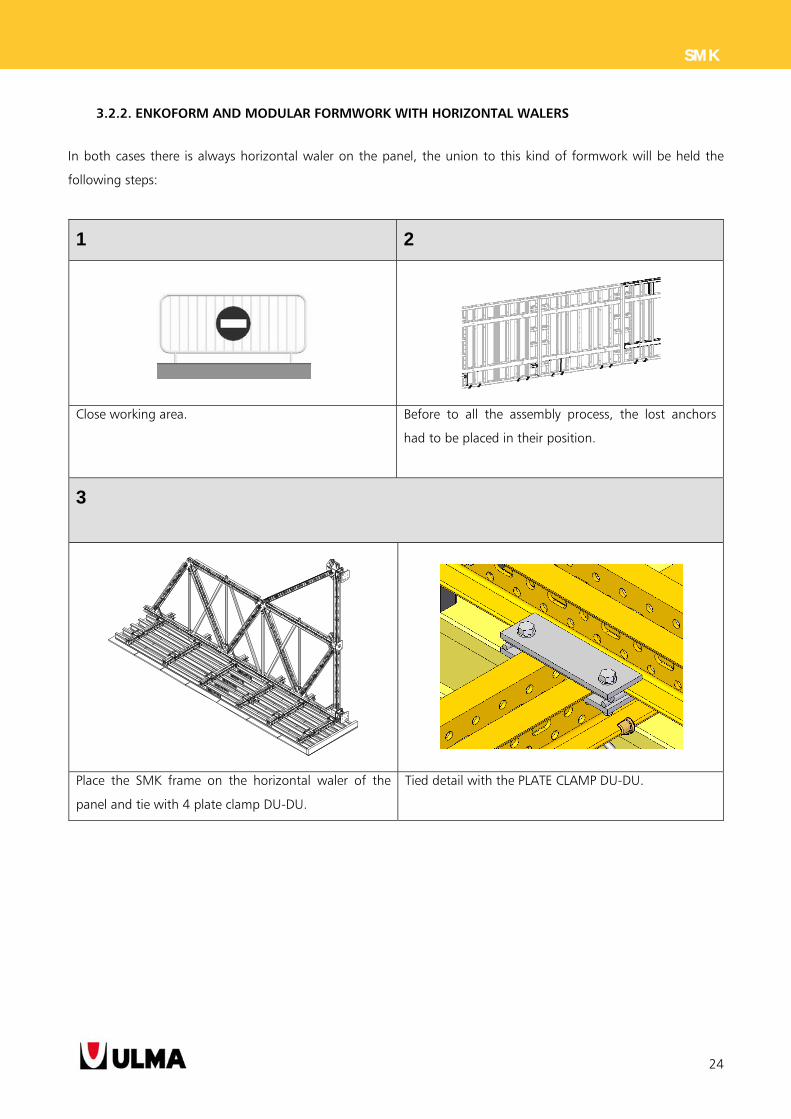
3.2.2. ENKOFORM AND MODULAR FORMWORK WITH HORIZONTAL WALERS
In both cases there is always horizontal waler on the panel, the union to this kind of formwork will be held the
following steps:
1 2
Close working area. Before to all the assembly process, the lost anchors
had to be placed in their position.
3
Place the SMK frame on the horizontal waler of the
panel and tie with 4 plate clamp DU-DU.
Tied detail with the PLATE CLAMP DU-DU.
25
SMK
3b 4
Detail of the junction with plate clamp DU-DU for
another position.
After assembling both frames on the panel they
should be braced using couplers and tubes.
5 6
We recommend placing the "Adjustment jack MK-
120” on the vertical profile making contact against the
horizontal waler to avoid movement when lifting. Place
1 adjustment jack per frame.
After placing the frame and panels in the final
position, they should be fixed with the corresponding
anchoring system.
26
SMK
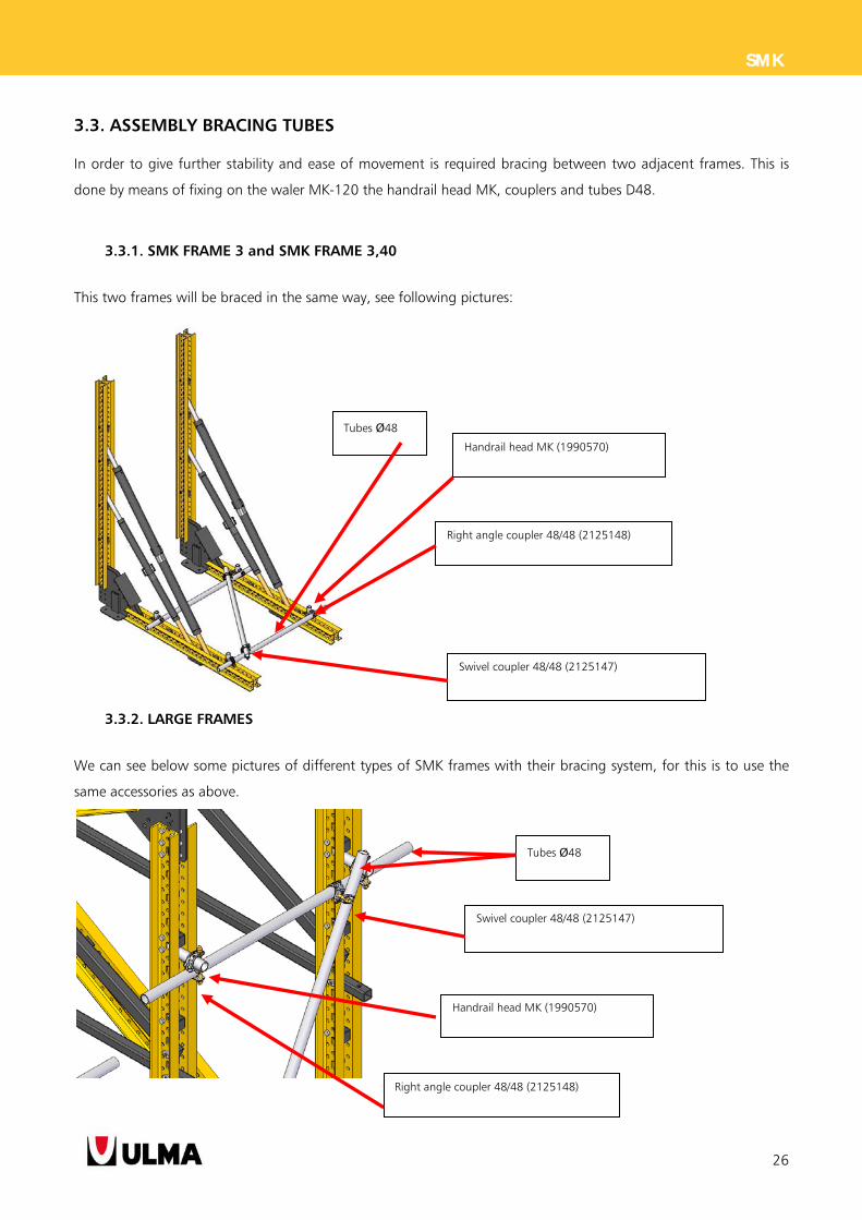
3.3. ASSEMBLY BRACING TUBES
In order to give further stability and ease of movement is required bracing between two adjacent frames. This is
done by means of fixing on the waler MK-120 the handrail head MK, couplers and tubes D48.
3.3.1. SMK FRAME 3 and SMK FRAME 3,40
This two frames will be braced in the same way, see following pictures:
3.3.2. LARGE FRAMES
We can see below some pictures of different types of SMK frames with their bracing system, for this is to use the
same accessories as above.
Tubes Ø48
Right angle coupler 48/48 (2125148)
Swivel coupler 48/48 (2125147)
Handrail head MK (1990570)
Tubes Ø48
Swivel coupler 48/48 (2125147)
Handrail head MK (1990570)
Right angle coupler 48/48 (2125148)
27
SMK
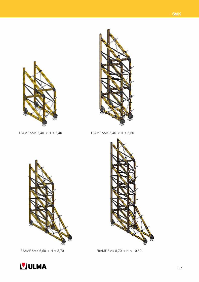
FRAME SMK 3,40 < H ≤ 5,40 FRAME SMK 5,40 < H ≤ 6,60
FRAME SMK 6,60 < H ≤ 8,70 FRAME SMK 8,70 < H ≤ 10,50
28
SMK
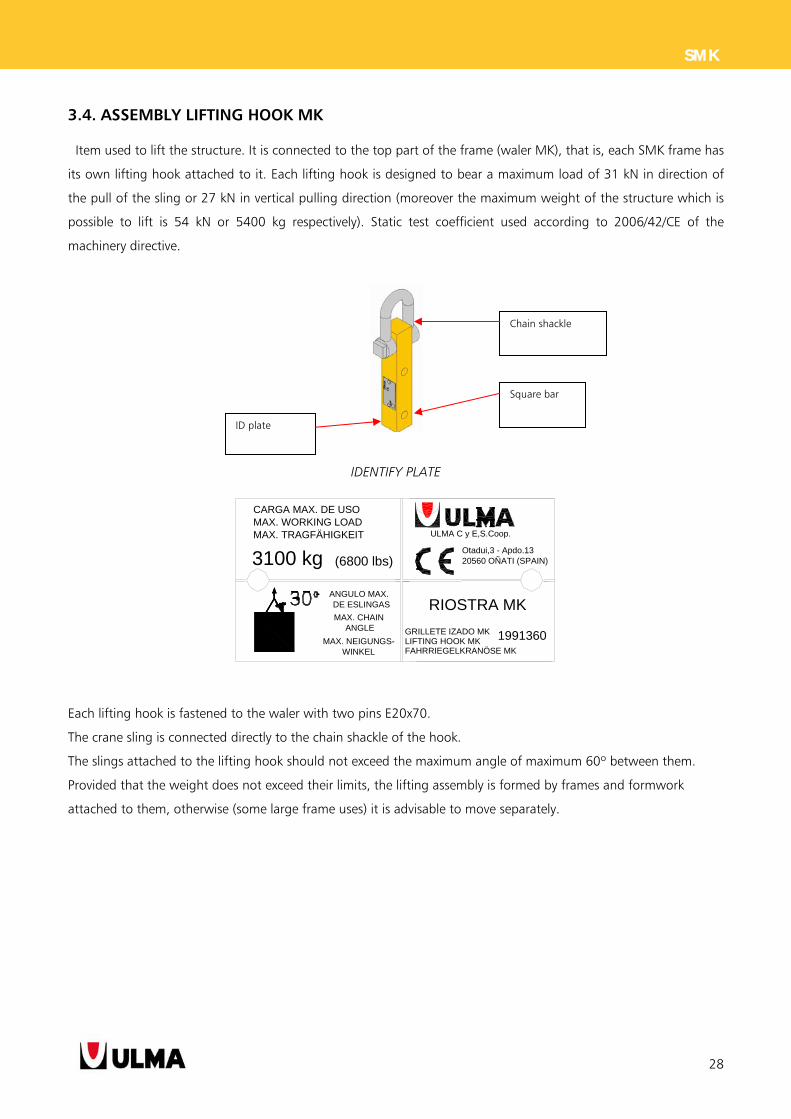
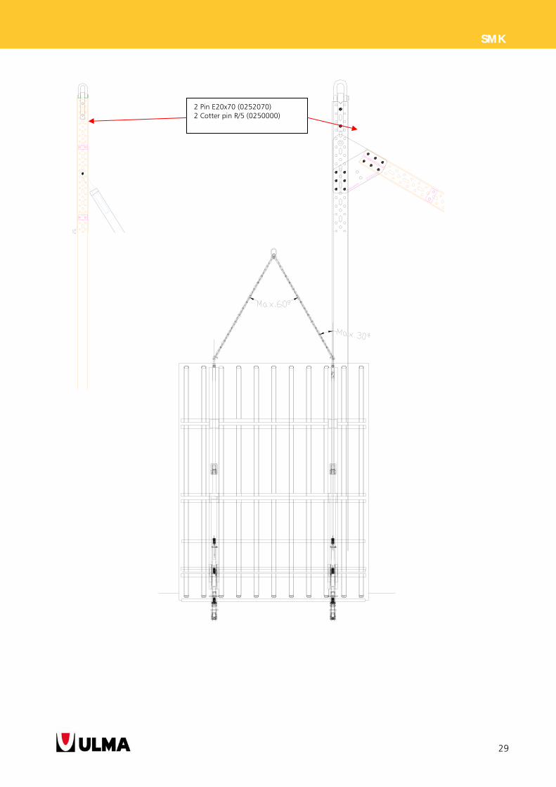
3.4. ASSEMBLY LIFTING HOOK MK
Item used to lift the structure. It is connected to the top part of the frame (waler MK), that is, each SMK frame has
its own lifting hook attached to it. Each lifting hook is designed to bear a maximum load of 31 kN in direction of
the pull of the sling or 27 kN in vertical pulling direction (moreover the maximum weight of the structure which is
possible to lift is 54 kN or 5400 kg respectively). Static test coefficient used according to 2006/42/CE of the
machinery directive.
IDENTIFY PLATE
Each lifting hook is fastened to the waler with two pins E20x70.
The crane sling is connected directly to the chain shackle of the hook.
The slings attached to the lifting hook should not exceed the maximum angle of maximum 60º between them.
Provided that the weight does not exceed their limits, the lifting assembly is formed by frames and formwork
attached to them, otherwise (some large frame uses) it is advisable to move separately.
ULMA C y E,S.Coop.
Otadui,3 - Apdo.1320560 OÑATI (SPAIN)
CARGA MAX. DE USOMAX. WORKING LOADMAX. TRAGFÄHIGKEIT
3100 kg (6800 lbs)
ANGULO MAX.DE ESLINGAS
MAX. CHAINANGLE
MAX. NEIGUNGS-WINKEL
RIOSTRA MK
GRILLETE IZADO MKLIFTING HOOK MKFAHRRIEGELKRANÖSE MK
1991360
Chain shackle
Square bar
ID plate
29
SMK
2 Pin E20x70 (0252070) 2 Cotter pin R/5 (0250000)
30
SMK
4. SOLUTIONS
Below a breakdown of all the elements forming the final configuration of the frames used.
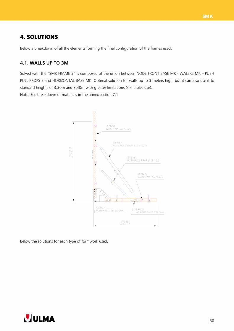
4.1. WALLS UP TO 3M
Solved with the “SMK FRAME 3” is composed of the union between NODE FRONT BASE MK - WALERS MK – PUSH
PULL PROPS E and HORIZONTAL BASE MK. Optimal solution for walls up to 3 meters high, but it can also use it to
standard heights of 3,30m and 3,40m with greater limitations (see tables use).
Note: See breakdown of materials in the annex section 7.1
Below the solutions for each type of formwork used.
31
SMK
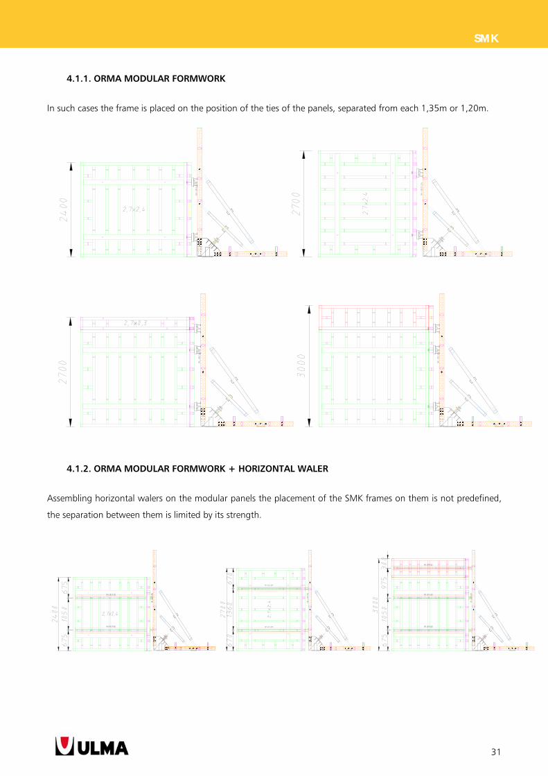
4.1.1. ORMA MODULAR FORMWORK
In such cases the frame is placed on the position of the ties of the panels, separated from each 1,35m or 1,20m.
4.1.2. ORMA MODULAR FORMWORK + HORIZONTAL WALER
Assembling horizontal walers on the modular panels the placement of the SMK frames on them is not predefined,
the separation between them is limited by its strength.
32
SMK
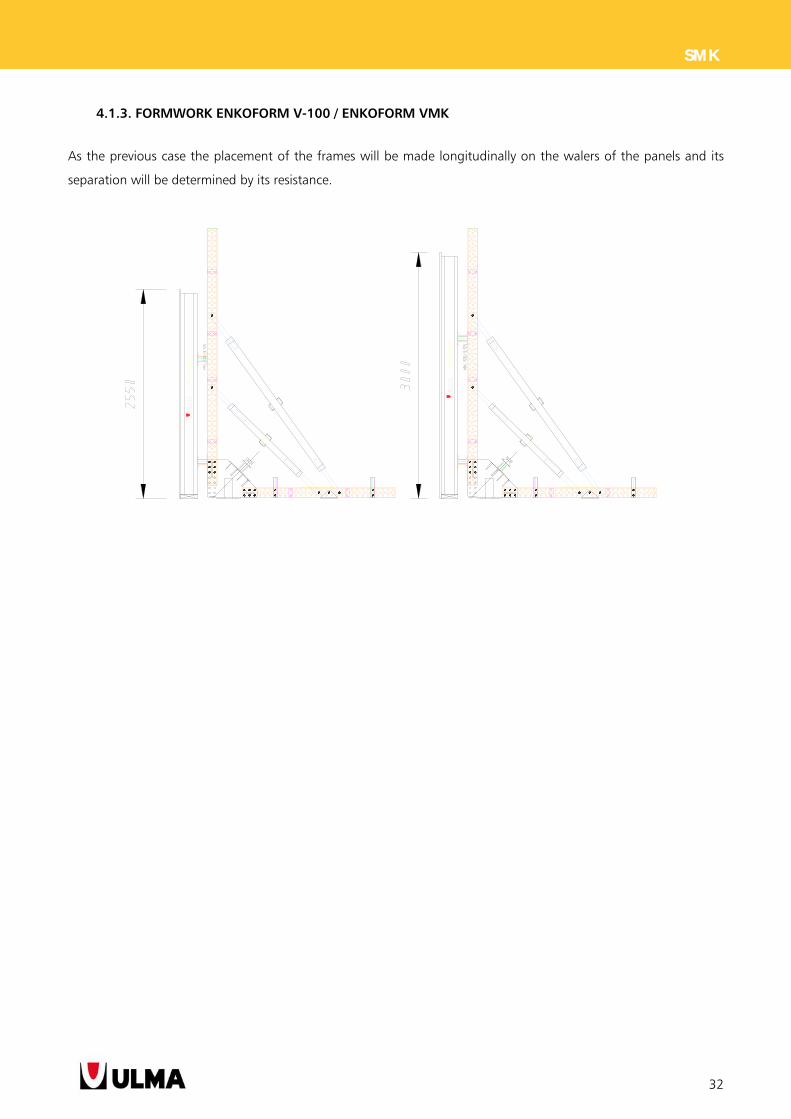
4.1.3. FORMWORK ENKOFORM V-100 / ENKOFORM VMK
As the previous case the placement of the frames will be made longitudinally on the walers of the panels and its
separation will be determined by its resistance.
33
SMK
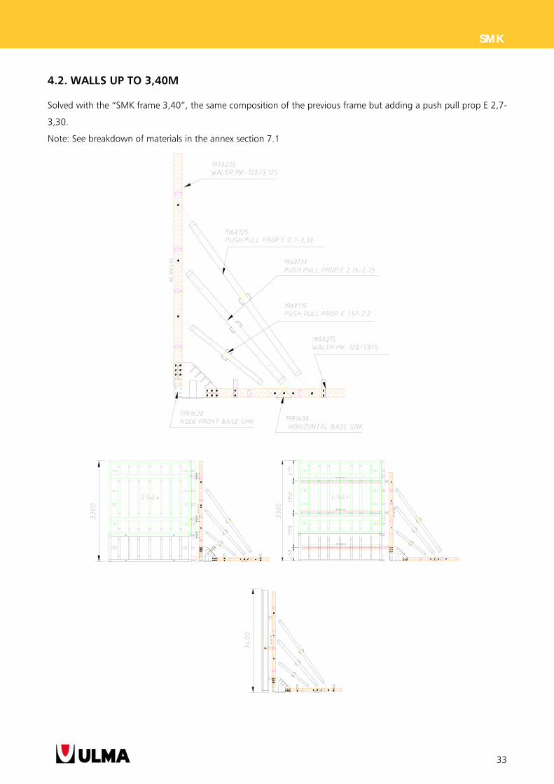
4.2. WALLS UP TO 3,40M
Solved with the “SMK frame 3,40”, the same composition of the previous frame but adding a push pull prop E 2,7-
3,30.
Note: See breakdown of materials in the annex section 7.1
34
SMK
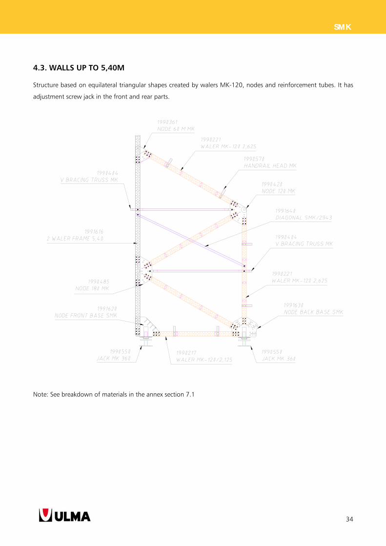
4.3. WALLS UP TO 5,40M
Structure based on equilateral triangular shapes created by walers MK-120, nodes and reinforcement tubes. It has
adjustment screw jack in the front and rear parts.
Note: See breakdown of materials in the annex section 7.1
35
SMK
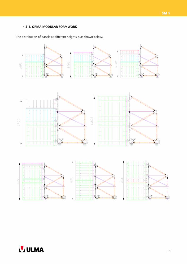
4.3.1. ORMA MODULAR FORMWORK
The distribution of panels at different heights is as shown below.
36
SMK
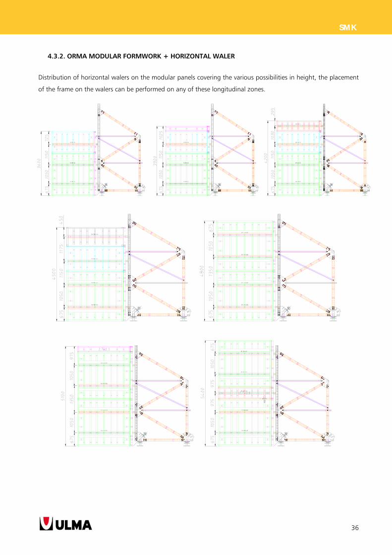
4.3.2. ORMA MODULAR FORMWORK + HORIZONTAL WALER
Distribution of horizontal walers on the modular panels covering the various possibilities in height, the placement
of the frame on the walers can be performed on any of these longitudinal zones.
37
SMK
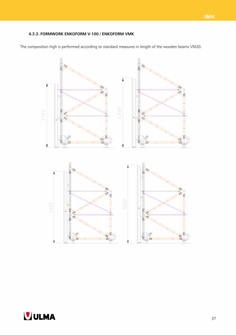
4.3.3. FORMWORK ENKOFORM V-100 / ENKOFORM VMK
The composition high is performed according to standard measures in length of the wooden beams VM20.
38
SMK
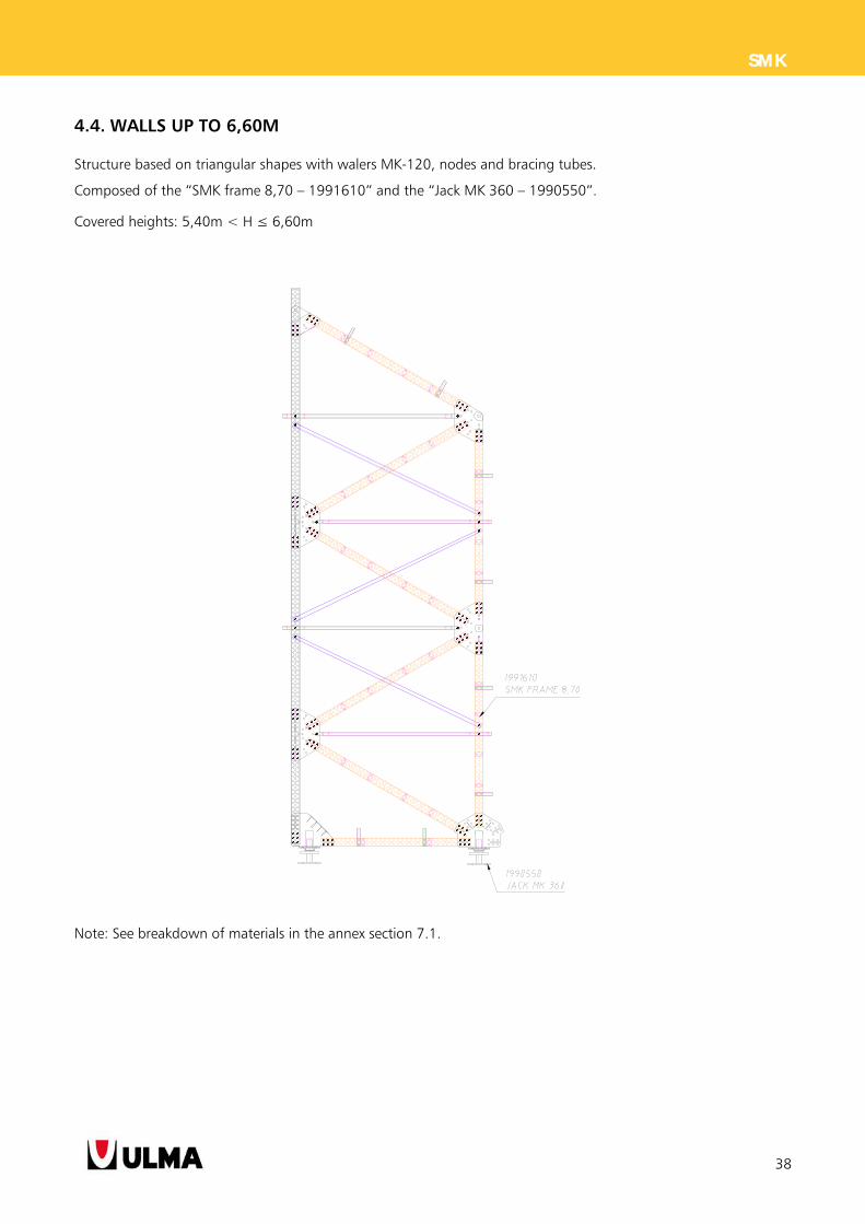
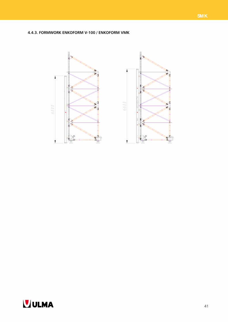
4.4. WALLS UP TO 6,60M
Structure based on triangular shapes with walers MK-120, nodes and bracing tubes.
Composed of the “SMK frame 8,70 – 1991610” and the “Jack MK 360 – 1990550”.
Covered heights: 5,40m < H ≤ 6,60m
Note: See breakdown of materials in the annex section 7.1.
39
SMK
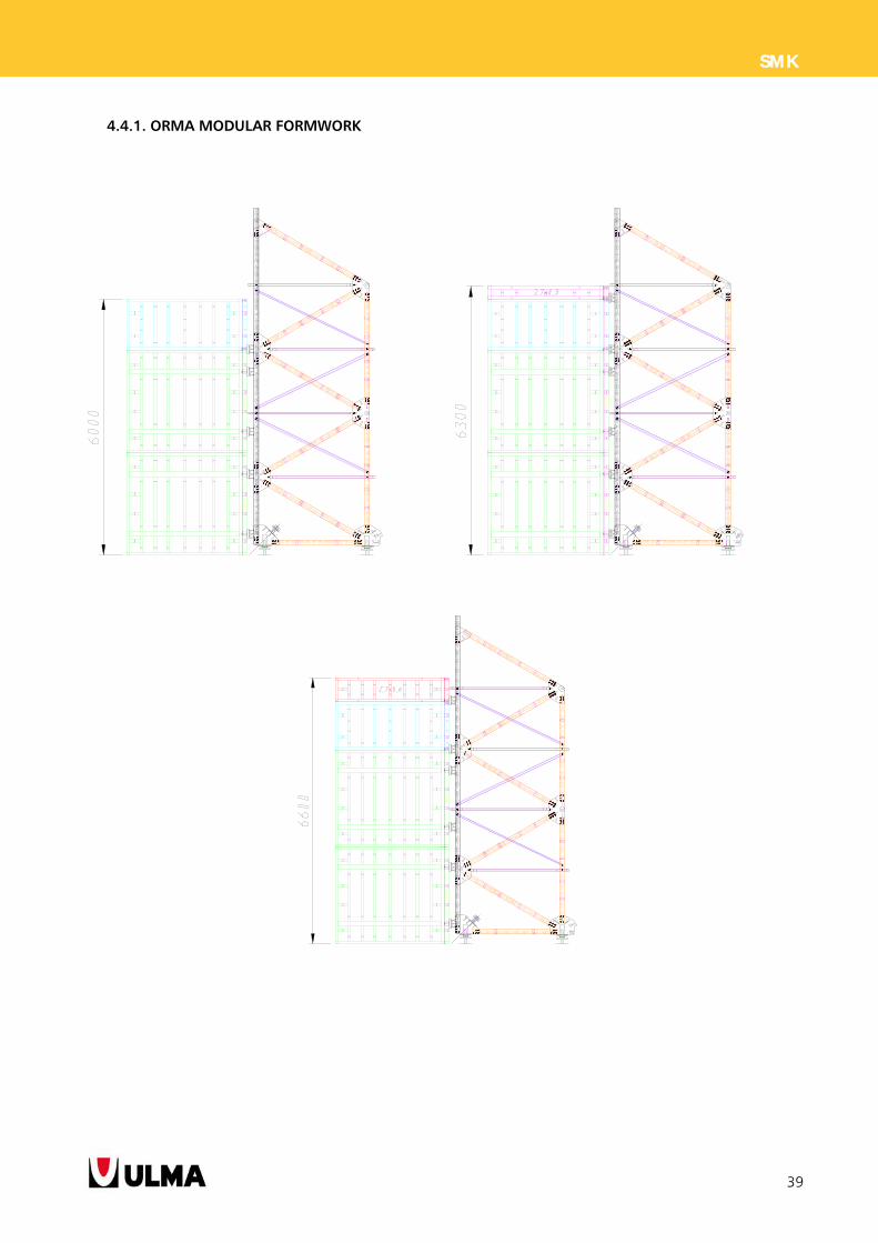
4.4.1. ORMA MODULAR FORMWORK
40
SMK
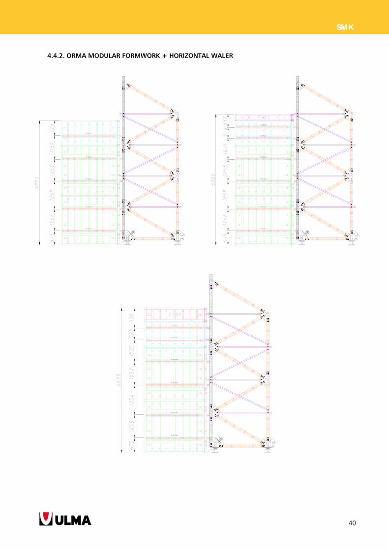
4.4.2. ORMA MODULAR FORMWORK + HORIZONTAL WALER
41
SMK
4.4.3. FORMWORK ENKOFORM V-100 / ENKOFORM VMK
42
SMK
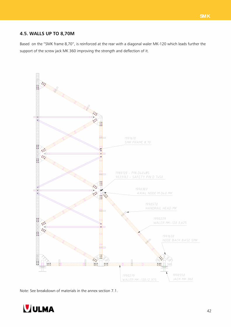
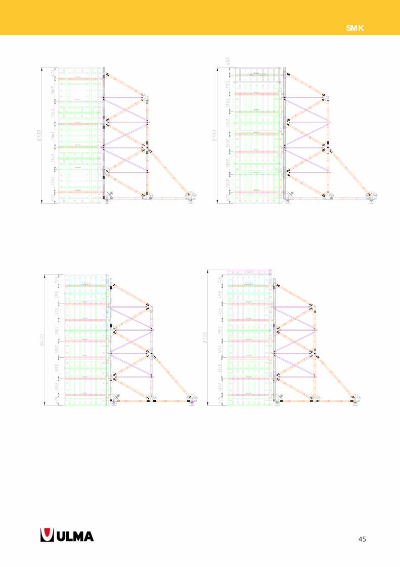
4.5. WALLS UP TO 8,70M
Based on the “SMK frame 8,70”, is reinforced at the rear with a diagonal waler MK-120 which leads further the
support of the screw jack MK 360 improving the strength and deflection of it.
Note: See breakdown of materials in the annex section 7.1.
43
SMK
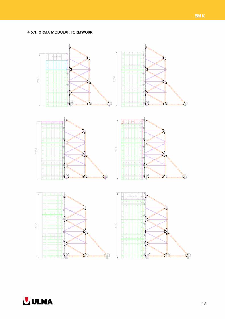
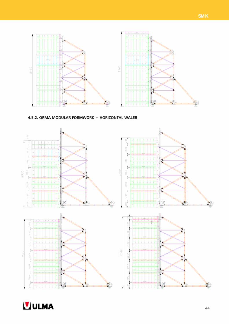
4.5.1. ORMA MODULAR FORMWORK
44
SMK
4.5.2. ORMA MODULAR FORMWORK + HORIZONTAL WALER
45
SMK
46
SMK
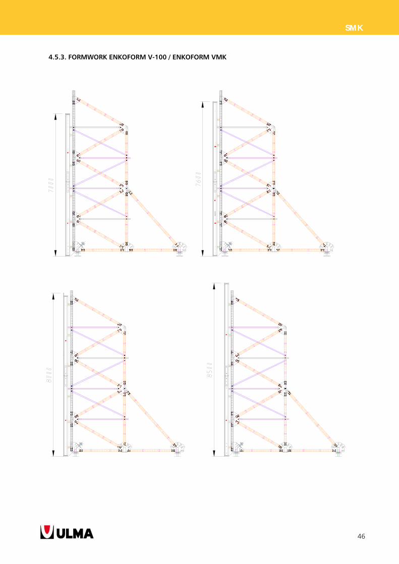
4.5.3. FORMWORK ENKOFORM V-100 / ENKOFORM VMK
47
SMK
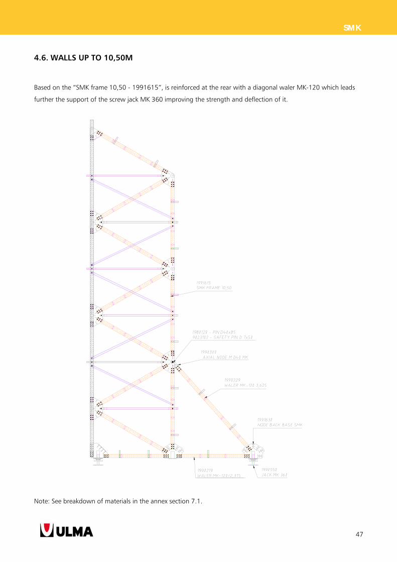
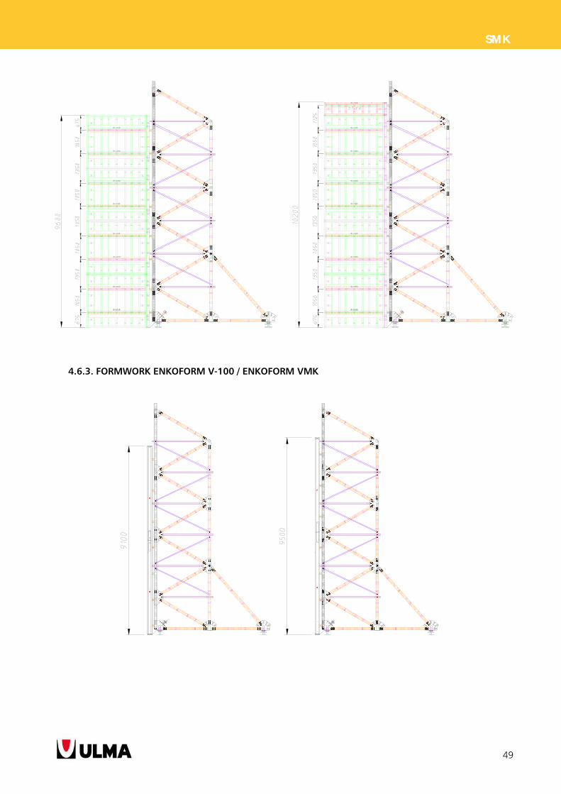
4.6. WALLS UP TO 10,50M
Based on the “SMK frame 10,50 - 1991615”, is reinforced at the rear with a diagonal waler MK-120 which leads
further the support of the screw jack MK 360 improving the strength and deflection of it.
Note: See breakdown of materials in the annex section 7.1.
48
SMK
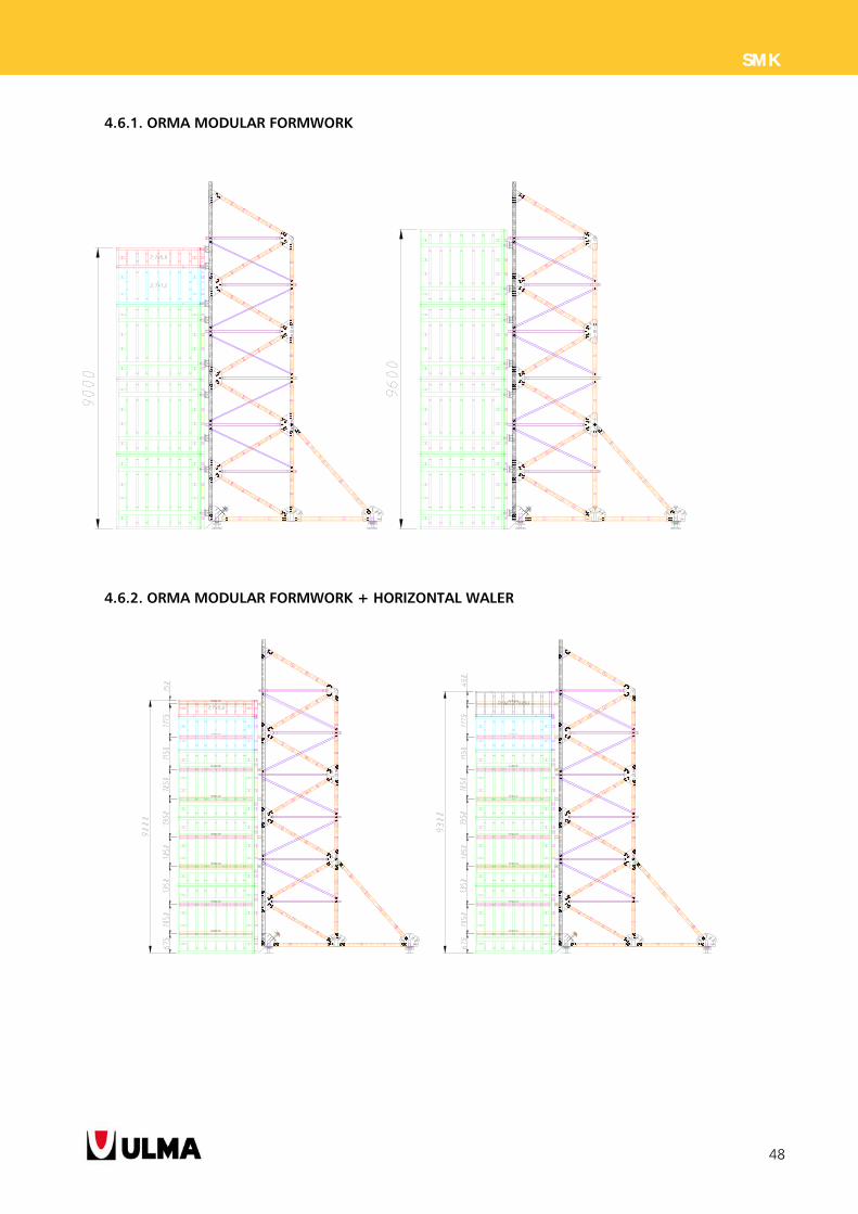
4.6.1. ORMA MODULAR FORMWORK
4.6.2. ORMA MODULAR FORMWORK + HORIZONTAL WALER
49
SMK
4.6.3. FORMWORK ENKOFORM V-100 / ENKOFORM VMK
50
SMK
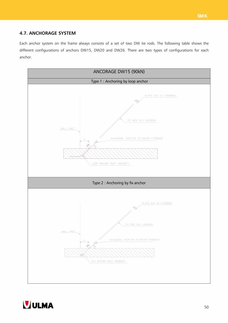
4.7. ANCHORAGE SYSTEM
Each anchor system on the frame always consists of a set of two DW tie rods. The following table shows the
different configurations of anchors DW15, DW20 and DW26. There are two types of configurations for each
anchor.
ANCORAGE DW15 (90kN)
Type 1 : Anchoring by loop anchor
Type 2 : Anchoring by fix anchor
51
SMK
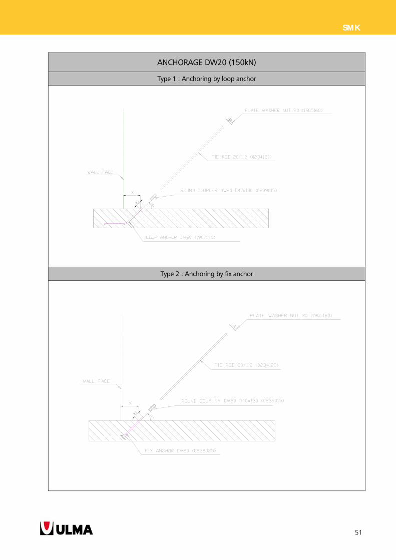
ANCHORAGE DW20 (150kN)
Type 1 : Anchoring by loop anchor
Type 2 : Anchoring by fix anchor
52
SMK
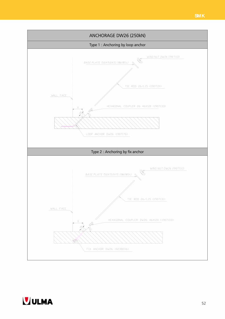
ANCHORAGE DW26 (250kN)
Type 1 : Anchoring by loop anchor
Type 2 : Anchoring by fix anchor
53
SMK
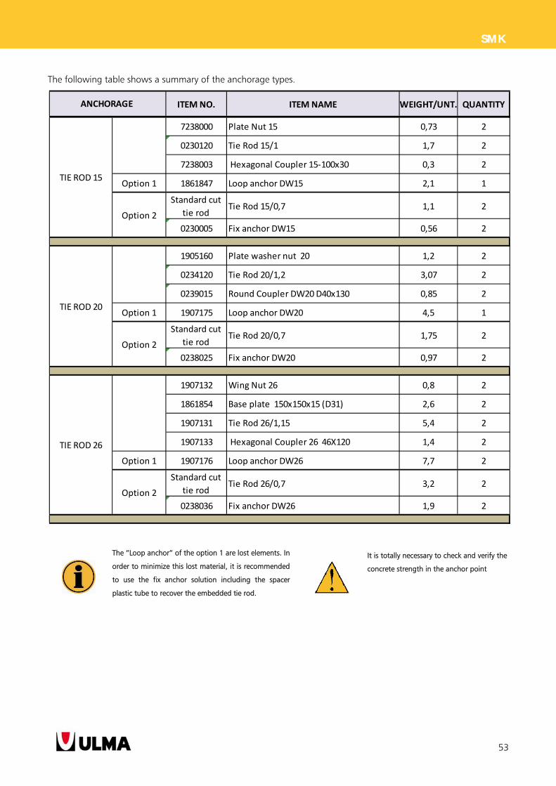
The following table shows a summary of the anchorage types.
ITEM NO. ITEM NAME WEIGHT/UNT. QUANTITY
7238000 Plate Nut 15 0,73 2
0230120 Tie Rod 15/1 1,7 2
7238003 Hexagonal Coupler 15‐100x30 0,3 2
Option 1 1861847 Loop anchor DW15 2,1 1
Standard cut
tie rodTie Rod 15/0,7 1,1 2
0230005 Fix anchor DW15 0,56 2
1905160 Plate washer nut 20 1,2 2
0234120 Tie Rod 20/1,2 3,07 2
0239015 Round Coupler DW20 D40x130 0,85 2
Option 1 1907175 Loop anchor DW20 4,5 1
Standard cut
tie rodTie Rod 20/0,7 1,75 2
0238025 Fix anchor DW20 0,97 2
1907132 Wing Nut 26 0,8 2
1861854 Base plate 150x150x15 (D31) 2,6 2
1907131 Tie Rod 26/1,15 5,4 2
1907133 Hexagonal Coupler 26 46X120 1,4 2
Option 1 1907176 Loop anchor DW26 7,7 2
Standard cut
tie rodTie Rod 26/0,7 3,2 2
0238036 Fix anchor DW26 1,9 2
TIE ROD 26
Option 2
ANCHORAGE
TIE ROD 15
Option 2
TIE ROD 20
Option 2
The “Loop anchor” of the option 1 are lost elements. In
order to minimize this lost material, it is recommended
to use the fix anchor solution including the spacer
plastic tube to recover the embedded tie rod.
It is totally necessary to check and verify the
concrete strength in the anchor point
54
SMK
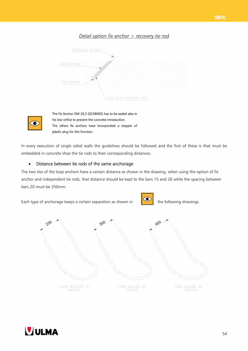
Detail option fix anchor + recovery tie rod
In every execution of single sided walls the guidelines should be followed and the first of these is that must be
embedded in concrete shoe the tie rods to their corresponding distances.
Distance between tie rods of the same anchorage
The two ties of the loop anchors have a certain distance as shown in the drawing, when using the option of fix
anchor and independent tie rods, that distance should be kept to the bars 15 and 26 while the spacing between
bars 20 must be 350mm.
Each type of anchorage keeps a certain separation as shown in the following drawings.
230300 400
The Fix Anchor DW 26,5 (0238065) has to be sealed also in
his low orifice to prevent the concrete introduction.
The others fix anchors have incorporated a stopper of
plastic plug for this function.
55
SMK
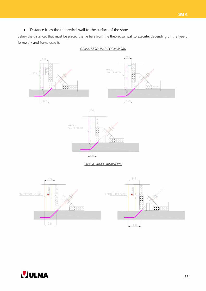
Distance from the theoretical wall to the surface of the shoe
Below the distances that must be placed the tie bars from the theoretical wall to execute, depending on the type of
formwork and frame used it.
ORMA MODULAR FORMWORK
ENKOFORM FORMWORK
56
SMK
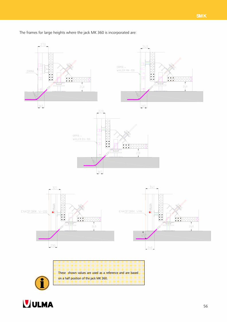
The frames for large heights where the jack MK 360 is incorporated are:
These shown values are used as a reference and are based
on a half position of the jack MK 360.
57
SMK
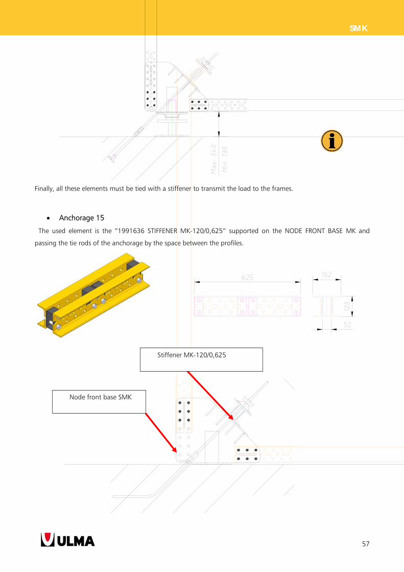
Finally, all these elements must be tied with a stiffener to transmit the load to the frames.
Anchorage 15
The used element is the “1991636 STIFFENER MK-120/0,625” supported on the NODE FRONT BASE MK and
passing the tie rods of the anchorage by the space between the profiles.
Stiffener MK-120/0,625
Node front base SMK
58
SMK
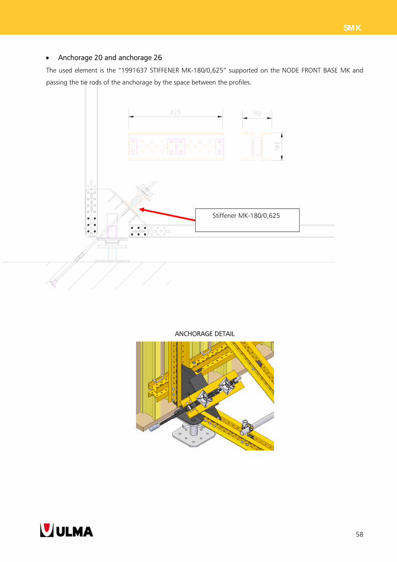
Anchorage 20 and anchorage 26
The used element is the “1991637 STIFFENER MK-180/0,625” supported on the NODE FRONT BASE MK and
passing the tie rods of the anchorage by the space between the profiles.
ANCHORAGE DETAIL
Stiffener MK-180/0,625
59
SMK
5. SYSTEM FEATURES
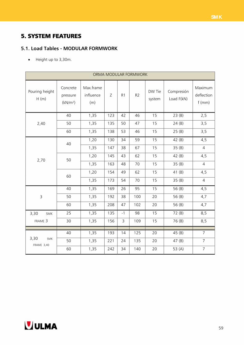
5.1. Load Tables - MODULAR FORMWORK
Height up to 3,30m.
ORMA MODULAR FORMWORK
Pouring height
H (m)
Concrete
pressure
(kN/m²)
Max.frame
influence
(m)
Z R1 R2 DW Tie
system
Compresión
Load F(kN)
Maximum
deflection
f (mm)
2,40
40 1,35 123 42 46 15 23 (B) 2,5
50 1,35 135 50 47 15 24 (B) 3,5
60 1,35 138 53 46 15 25 (B) 3,5
2,70
40 1,20 130 34 59 15 42 (B) 4,5
1,35 147 38 67 15 35 (B) 4
50 1,20 145 43 62 15 42 (B) 4,5
1,35 163 48 70 15 35 (B) 4
60 1,20 154 49 62 15 41 (B) 4,5
1,35 173 54 70 15 35 (B) 4
3
40 1,35 169 26 95 15 56 (B) 4,5
50 1,35 192 38 100 20 56 (B) 4,7
60 1,35 208 47 102 20 56 (B) 4,7
3,30 SMK
FRAME 3
25 1,35 135 -1 98 15 72 (B) 8,5
30 1,35 156 3 109 15 76 (B) 8,5
3,30 SMK
FRAME 3,40
40 1,35 193 14 125 20 45 (B) 7
50 1,35 221 24 135 20 47 (B) 7
60 1,35 242 34 140 20 53 (A) 7
60
SMK
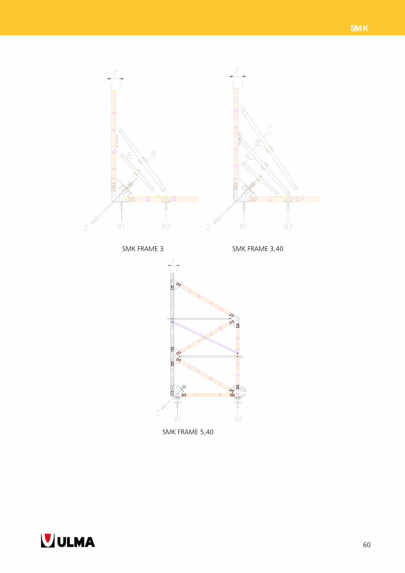
SMK FRAME 3 SMK FRAME 3,40
SMK FRAME 5,40
61
SMK
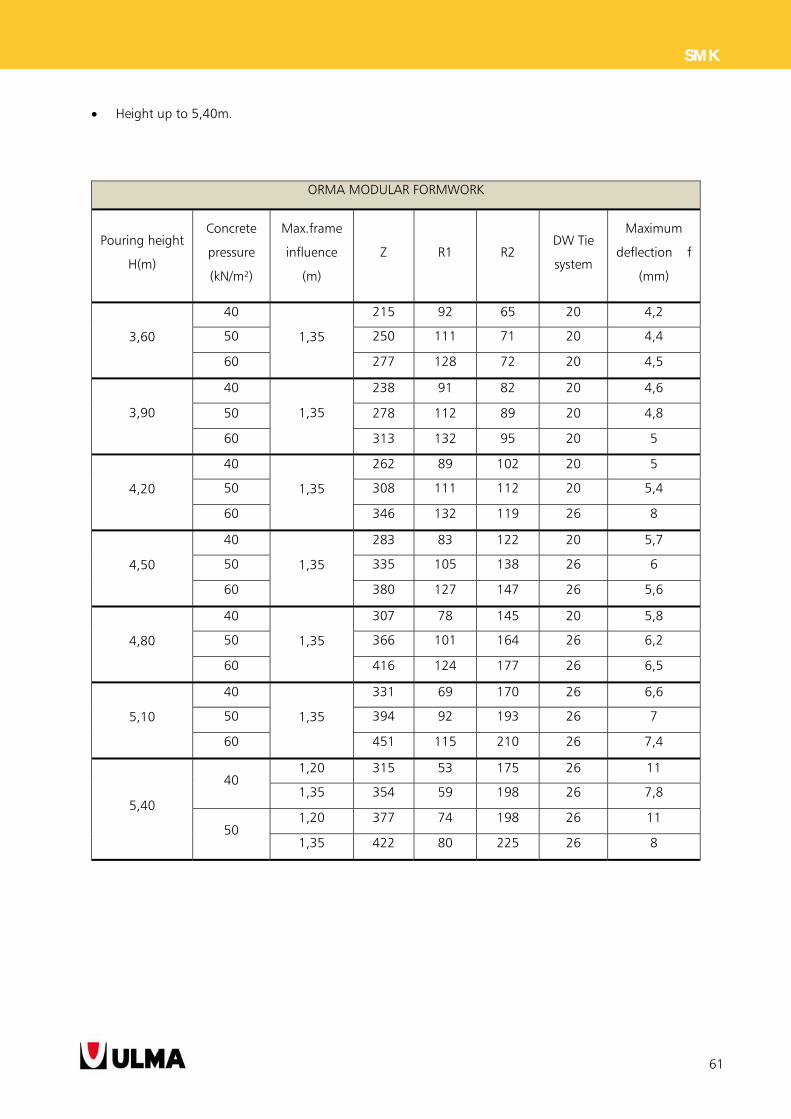
Height up to 5,40m.
ORMA MODULAR FORMWORK
Pouring height
H(m)
Concrete
pressure
(kN/m²)
Max.frame
influence
(m)
Z R1 R2 DW Tie
system
Maximum
deflection f
(mm)
3,60
40
1,35
215 92 65 20 4,2
50 250 111 71 20 4,4
60 277 128 72 20 4,5
3,90
40
1,35
238 91 82 20 4,6
50 278 112 89 20 4,8
60 313 132 95 20 5
4,20
40
1,35
262 89 102 20 5
50 308 111 112 20 5,4
60 346 132 119 26 8
4,50
40
1,35
283 83 122 20 5,7
50 335 105 138 26 6
60 380 127 147 26 5,6
4,80
40
1,35
307 78 145 20 5,8
50 366 101 164 26 6,2
60 416 124 177 26 6,5
5,10
40
1,35
331 69 170 26 6,6
50 394 92 193 26 7
60 451 115 210 26 7,4
5,40
40 1,20 315 53 175 26 11
1,35 354 59 198 26 7,8
50 1,20 377 74 198 26 11
1,35 422 80 225 26 8
62
SMK
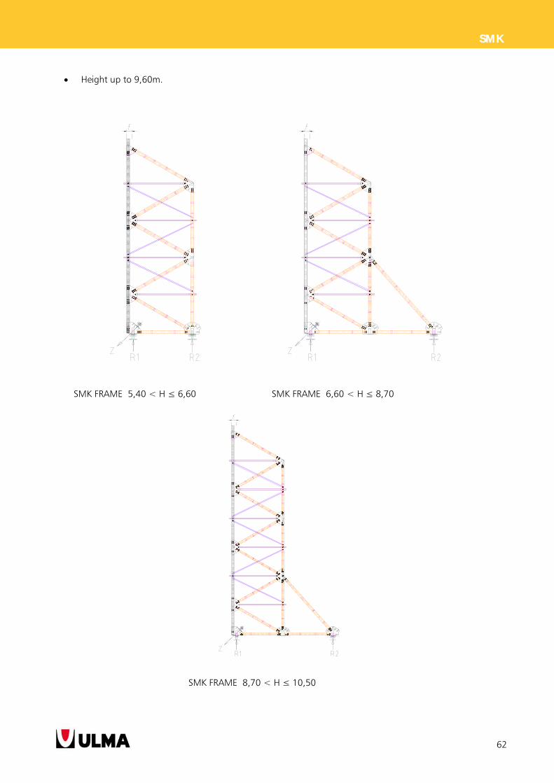
Height up to 9,60m.
SMK FRAME 5,40 < H ≤ 6,60 SMK FRAME 6,60 < H ≤ 8,70
SMK FRAME 8,70 < H ≤ 10,50
63
SMK
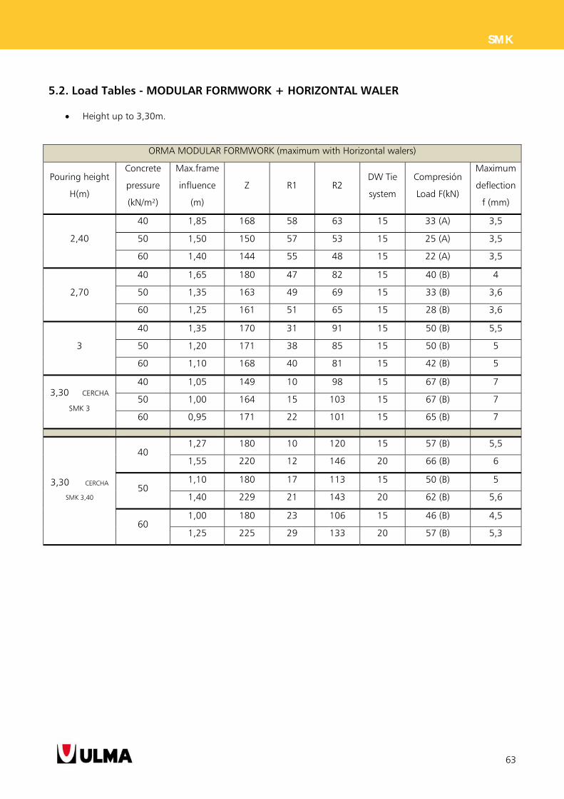
5.2. Load Tables - MODULAR FORMWORK + HORIZONTAL WALER
Height up to 3,30m.
ORMA MODULAR FORMWORK (maximum with Horizontal walers)
Pouring height
H(m)
Concrete
pressure
(kN/m²)
Max.frame
influence
(m)
Z R1 R2 DW Tie
system
Compresión
Load F(kN)
Maximum
deflection
f (mm)
2,40
40 1,85 168 58 63 15 33 (A) 3,5
50 1,50 150 57 53 15 25 (A) 3,5
60 1,40 144 55 48 15 22 (A) 3,5
2,70
40 1,65 180 47 82 15 40 (B) 4
50 1,35 163 49 69 15 33 (B) 3,6
60 1,25 161 51 65 15 28 (B) 3,6
3
40 1,35 170 31 91 15 50 (B) 5,5
50 1,20 171 38 85 15 50 (B) 5
60 1,10 168 40 81 15 42 (B) 5
3,30 CERCHA
SMK 3
40 1,05 149 10 98 15 67 (B) 7
50 1,00 164 15 103 15 67 (B) 7
60 0,95 171 22 101 15 65 (B) 7
3,30 CERCHA
SMK 3,40
40 1,27 180 10 120 15 57 (B) 5,5
1,55 220 12 146 20 66 (B) 6
50 1,10 180 17 113 15 50 (B) 5
1,40 229 21 143 20 62 (B) 5,6
60 1,00 180 23 106 15 46 (B) 4,5
1,25 225 29 133 20 57 (B) 5,3
64
SMK
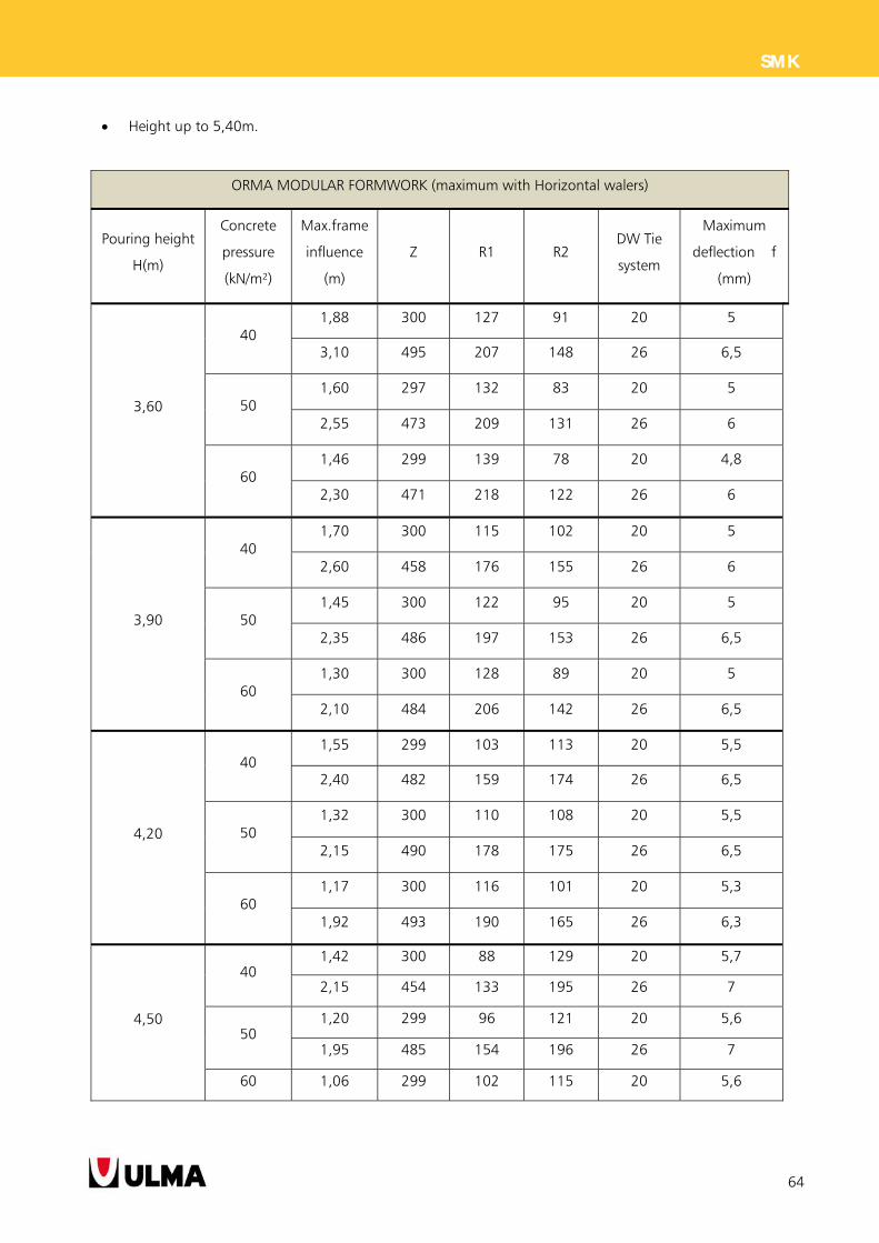
Height up to 5,40m.
ORMA MODULAR FORMWORK (maximum with Horizontal walers)
Pouring height
H(m)
Concrete
pressure
(kN/m²)
Max.frame
influence
(m)
Z R1 R2 DW Tie
system
Maximum
deflection f
(mm)
3,60
40 1,88 300 127 91 20 5
3,10 495 207 148 26 6,5
50 1,60 297 132 83 20 5
2,55 473 209 131 26 6
60 1,46 299 139 78 20 4,8
2,30 471 218 122 26 6
3,90
40 1,70 300 115 102 20 5
2,60 458 176 155 26 6
50 1,45 300 122 95 20 5
2,35 486 197 153 26 6,5
60 1,30 300 128 89 20 5
2,10 484 206 142 26 6,5
4,20
40 1,55 299 103 113 20 5,5
2,40 482 159 174 26 6,5
50 1,32 300 110 108 20 5,5
2,15 490 178 175 26 6,5
60 1,17 300 116 101 20 5,3
1,92 493 190 165 26 6,3
4,50
40 1,42 300 88 129 20 5,7
2,15 454 133 195 26 7
50 1,20 299 96 121 20 5,6
1,95 485 154 196 26 7
60 1,06 299 102 115 20 5,6
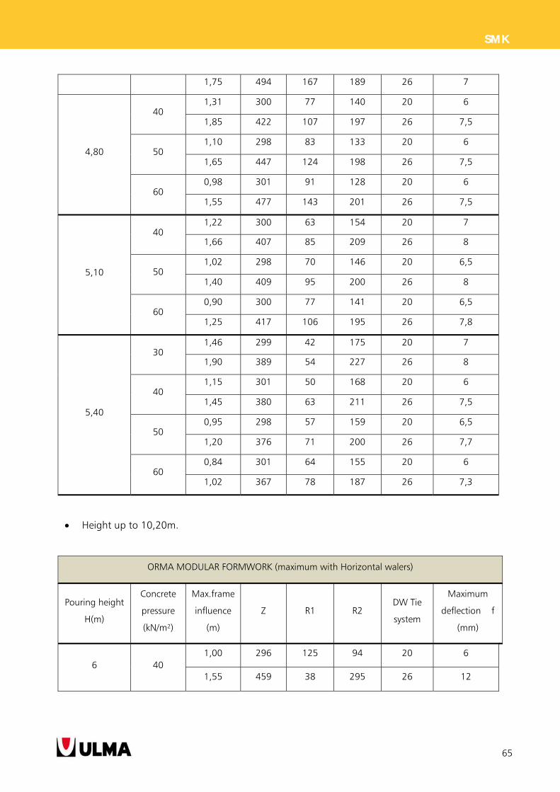
65
SMK
1,75 494 167 189 26 7
4,80
40 1,31 300 77 140 20 6
1,85 422 107 197 26 7,5
50 1,10 298 83 133 20 6
1,65 447 124 198 26 7,5
60 0,98 301 91 128 20 6
1,55 477 143 201 26 7,5
5,10
40 1,22 300 63 154 20 7
1,66 407 85 209 26 8
50 1,02 298 70 146 20 6,5
1,40 409 95 200 26 8
60 0,90 300 77 141 20 6,5
1,25 417 106 195 26 7,8
5,40
30 1,46 299 42 175 20 7
1,90 389 54 227 26 8
40 1,15 301 50 168 20 6
1,45 380 63 211 26 7,5
50 0,95 298 57 159 20 6,5
1,20 376 71 200 26 7,7
60 0,84 301 64 155 20 6
1,02 367 78 187 26 7,3
Height up to 10,20m.
ORMA MODULAR FORMWORK (maximum with Horizontal walers)
Pouring height
H(m)
Concrete
pressure
(kN/m²)
Max.frame
influence
(m)
Z R1 R2 DW Tie
system
Maximum
deflection f
(mm)
6 40 1,00 296 125 94 20 6
1,55 459 38 295 26 12
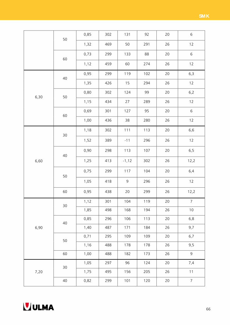
66
SMK
50 0,85 302 131 92 20 6
1,32 469 50 291 26 12
60 0,73 299 133 88 20 6
1,12 459 60 274 26 12
6,30
40 0,95 299 119 102 20 6,3
1,35 426 15 294 26 12
50 0,80 302 124 99 20 6,2
1,15 434 27 289 26 12
60 0,69 301 127 95 20 6
1,00 436 38 280 26 12
6,60
30 1,18 302 111 113 20 6,6
1,52 389 -11 296 26 12
40 0,90 298 113 107 20 6,5
1,25 413 -1,12 302 26 12,2
50 0,75 299 117 104 20 6,4
1,05 418 9 296 26 12
60 0,95 438 20 299 26 12,2
6,90
30 1,12 301 104 119 20 7
1,85 498 168 194 26 10
40 0,85 296 106 113 20 6,8
1,40 487 171 184 26 9,7
50 0,71 295 109 109 20 6,7
1,16 488 178 178 26 9,5
60 1,00 488 182 173 26 9
7,20 30
1,05 297 96 124 20 7,4
1,75 495 156 205 26 11
40 0,82 299 101 120 20 7
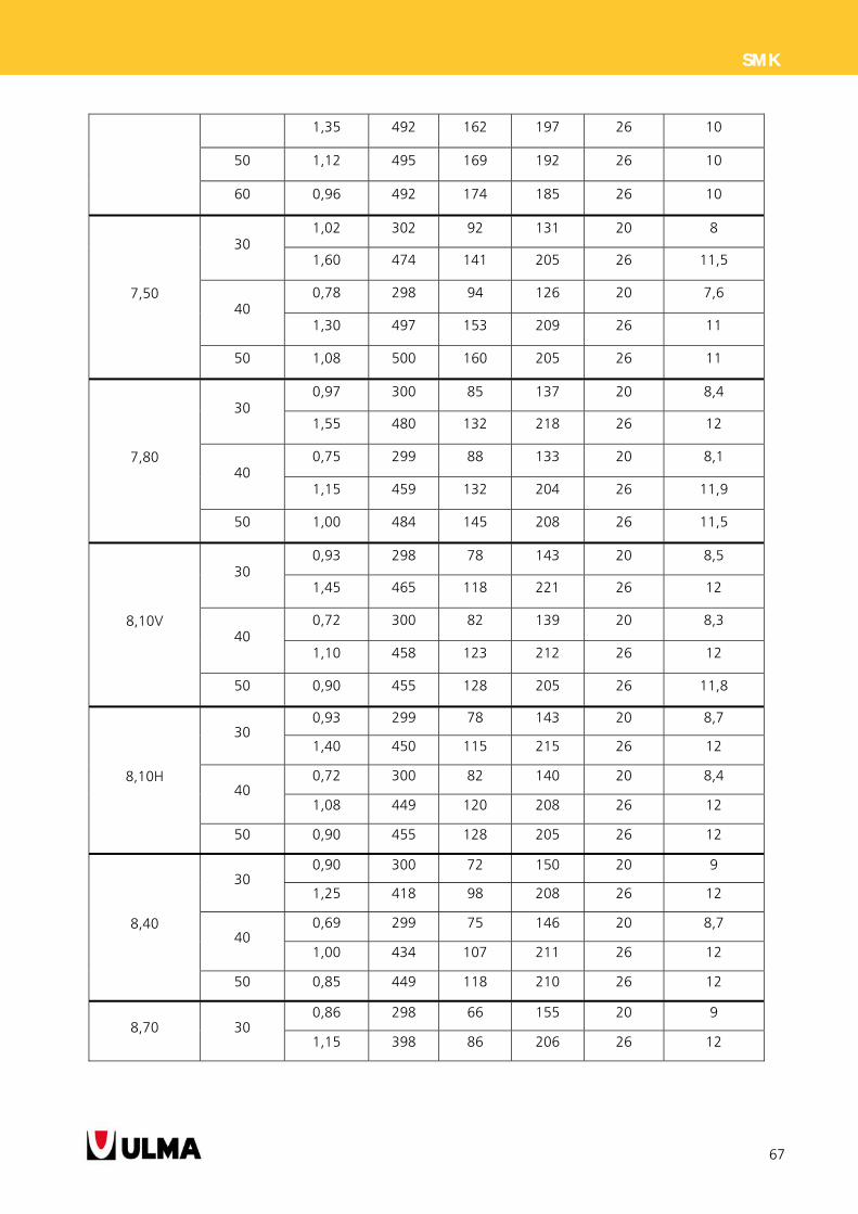
67
SMK
1,35 492 162 197 26 10
50 1,12 495 169 192 26 10
60 0,96 492 174 185 26 10
7,50
30 1,02 302 92 131 20 8
1,60 474 141 205 26 11,5
40 0,78 298 94 126 20 7,6
1,30 497 153 209 26 11
50 1,08 500 160 205 26 11
7,80
30 0,97 300 85 137 20 8,4
1,55 480 132 218 26 12
40 0,75 299 88 133 20 8,1
1,15 459 132 204 26 11,9
50 1,00 484 145 208 26 11,5
8,10V
30 0,93 298 78 143 20 8,5
1,45 465 118 221 26 12
40 0,72 300 82 139 20 8,3
1,10 458 123 212 26 12
50 0,90 455 128 205 26 11,8
8,10H
30 0,93 299 78 143 20 8,7
1,40 450 115 215 26 12
40 0,72 300 82 140 20 8,4
1,08 449 120 208 26 12
50 0,90 455 128 205 26 12
8,40
30 0,90 300 72 150 20 9
1,25 418 98 208 26 12
40 0,69 299 75 146 20 8,7
1,00 434 107 211 26 12
50 0,85 449 118 210 26 12
8,70 30 0,86 298 66 155 20 9
1,15 398 86 206 26 12
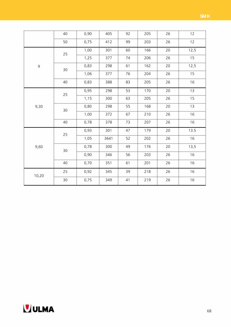
68
SMK
40 0,90 405 92 205 26 12
50 0,75 412 99 203 26 12
9
25 1,00 301 60 166 20 12,5
1,25 377 74 206 26 15
30 0,83 298 61 162 20 12,5
1,06 377 76 204 26 15
40 0,83 388 83 205 26 16
9,30
25 0,95 298 53 170 20 13
1,15 300 63 205 26 15
30 0,80 298 55 168 20 13
1,00 372 67 210 26 16
40 0,78 378 73 207 26 16
9,60
25 0,93 301 47 179 20 13.5
1,05 3641 52 202 26 16
30 0,78 300 49 176 20 13,5
0,90 346 56 203 26 16
40 0,70 351 61 201 26 16
10,20 25 0,92 345 39 218 26 16
30 0,75 349 41 219 26 16
69
SMK
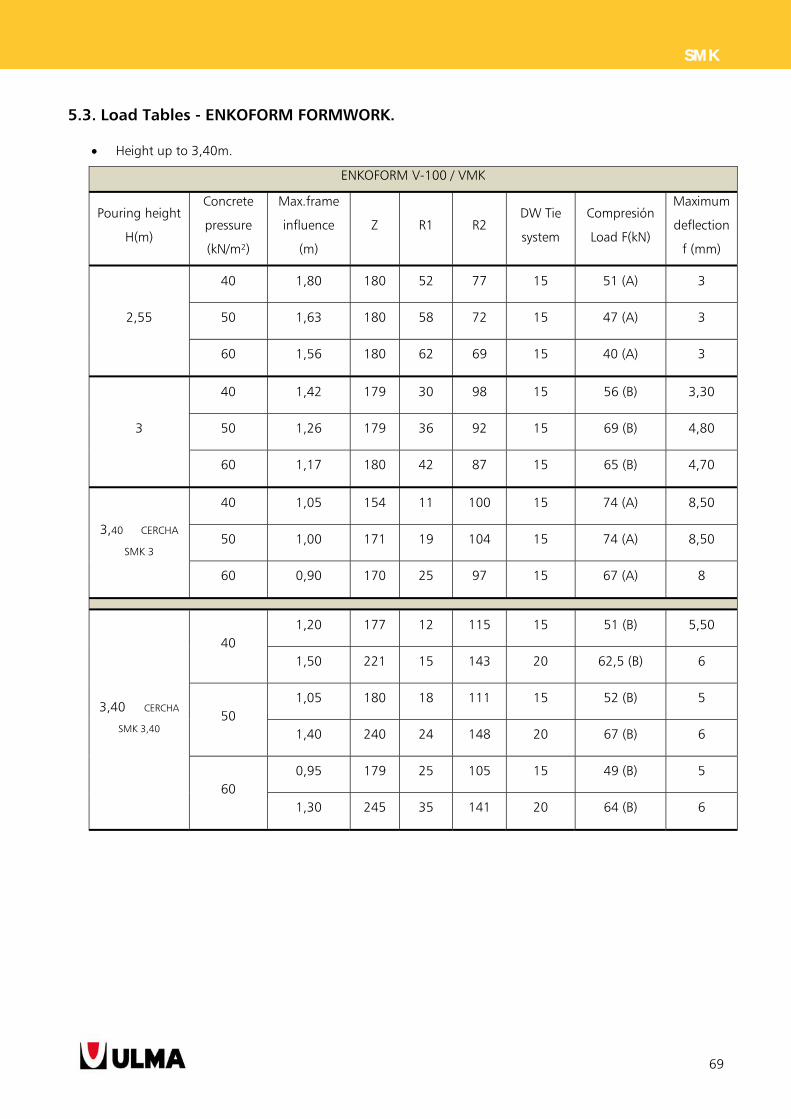
5.3. Load Tables - ENKOFORM FORMWORK.
Height up to 3,40m.
ENKOFORM V-100 / VMK
Pouring height
H(m)
Concrete
pressure
(kN/m²)
Max.frame
influence
(m)
Z R1 R2 DW Tie
system
Compresión
Load F(kN)
Maximum
deflection
f (mm)
2,55
40 1,80 180 52 77 15 51 (A) 3
50 1,63 180 58 72 15 47 (A) 3
60 1,56 180 62 69 15 40 (A) 3
3
40 1,42 179 30 98 15 56 (B) 3,30
50 1,26 179 36 92 15 69 (B) 4,80
60 1,17 180 42 87 15 65 (B) 4,70
3,40 CERCHA
SMK 3
40 1,05 154 11 100 15 74 (A) 8,50
50 1,00 171 19 104 15 74 (A) 8,50
60 0,90 170 25 97 15 67 (A) 8
3,40 CERCHA
SMK 3,40
40 1,20 177 12 115 15 51 (B) 5,50
1,50 221 15 143 20 62,5 (B) 6
50 1,05 180 18 111 15 52 (B) 5
1,40 240 24 148 20 67 (B) 6
60 0,95 179 25 105 15 49 (B) 5
1,30 245 35 141 20 64 (B) 6
70
SMK
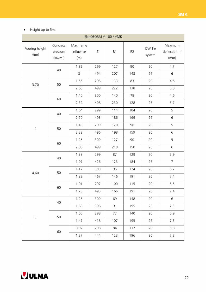
Height up to 5m.
ENKOFORM V-100 / VMK
Pouring height
H(m)
Concrete
pressure
(kN/m²)
Max.frame
influence
(m)
Z R1 R2 DW Tie
system
Maximum
deflection f
(mm)
3,70
40 1,82 299 127 90 20 4,7
3 494 207 148 26 6
50 1,55 298 133 83 20 4,6
2,60 499 222 138 26 5,8
60 1,40 300 140 78 20 4,6
2,32 498 230 128 26 5,7
4
40 1,64 299 114 104 20 5
2,70 493 186 169 26 6
50 1,40 299 120 96 20 5
2,32 496 198 159 26 6
60 1,25 300 127 90 20 5
2,08 499 210 150 26 6
4,60
40 1,38 299 87 129 20 5,9
1,97 426 123 184 26 7
50 1,17 300 95 124 20 5,7
1,82 467 146 191 26 7,4
60 1,01 297 100 115 20 5,5
1,70 495 166 191 26 7,4
5
40 1,25 300 69 148 20 6
1,65 396 91 195 26 7,3
50 1,05 298 77 140 20 5,9
1,47 418 107 195 26 7,3
60 0,92 298 84 132 20 5,8
1,37 444 123 196 26 7,3

71
SMK
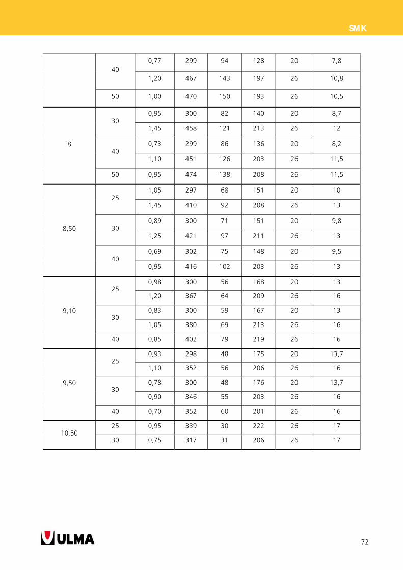
Height up to 10,50m.
ENKOFORM V-100 / VMK
Pouring height
H(m)
Concrete
pressure
(kN/m²)
Max.frame
influence
(m)
Z R1 R2 DW Tie
system
Maximum
deflection f
(mm)
6
40 1,00 297 127 93 20 6
1,55 460 39 296 26 12
50 0,85 301 133 91 20 6
1,35 480 52 297 26 12
60 0,73 298 135 86 20 5,8
1,15 473 62 282 26 12
6,60
30 1,16 298 111 110 20 6,7
1,75 450 -15 342 26 13,8
40 0,90 297 115 105 20 6,6
1,40 462 2,5 338 26 13,6
50 0,75 299 119 102 20 6,4
1,20 478 9 338 26 13,6
60 1,05 485 21 332 26 13
7
30 1,10 300 99 122 20 7,30
1,60 3435 141 177 26 10
40 0,85 300 104 118 20 7
1,28 451 152 176 26 10
50 0,70 299 108 113 20 7
1,05 448 157 169 26 9,70
60 0,90 446 164 161 26 9
7,60 30 1,00 299 90 131 20 8
1,57 469 137 205 26 11
72
SMK
40 0,77 299 94 128 20 7,8
1,20 467 143 197 26 10,8
50 1,00 470 150 193 26 10,5
8
30 0,95 300 82 140 20 8,7
1,45 458 121 213 26 12
40 0,73 299 86 136 20 8,2
1,10 451 126 203 26 11,5
50 0,95 474 138 208 26 11,5
8,50
25 1,05 297 68 151 20 10
1,45 410 92 208 26 13
30 0,89 300 71 151 20 9,8
1,25 421 97 211 26 13
40 0,69 302 75 148 20 9,5
0,95 416 102 203 26 13
9,10
25 0,98 300 56 168 20 13
1,20 367 64 209 26 16
30 0,83 300 59 167 20 13
1,05 380 69 213 26 16
40 0,85 402 79 219 26 16
9,50
25 0,93 298 48 175 20 13,7
1,10 352 56 206 26 16
30 0,78 300 48 176 20 13,7
0,90 346 55 203 26 16
40 0,70 352 60 201 26 16
10,50 25 0,95 339 30 222 26 17
30 0,75 317 31 206 26 17
73
SMK
6. CONDITIONS OF USE
6.1. GENERAL CONDITIONS OF USE:
Follow the instructions for the Project in
execution at all times.
Follow the general manufacturer´s instructions
at all times.
Formwork shall be assembled and stripped by
qualified personnel, who are supervised,
overseen and managed by a competent person.
If the working area is closet o high voltaje power
lines, power should be shut off while working is
in progress. If this is not possible, take the
necessary protective measures recommended in
the current applicable standard.
Do not work with formwork when wind speeds
are in excess of 60 km/h, or when there is ice or
snow.
The crane used must be strong enough for the
handling and assembly of the gangs.
The auxiliary lifting elements should be
appropriate for the loads to be lifted. They
should be checked before each use and
discarded if found to be faulty.
If lifting hooks are used, they should be used
following the instructions provided by the
manufacturer.
If due to conditions of the work environment,
the crane operator does not have the capacity to
view the whole trajectory over which the load is
moved, the transport operations will be guided
by a signalman, who will communicate with the
crane operator using predefined signals.
Under no circumstances shall people loiter
beneath or in the path of elevated loads.
6.1.1. Framing
For stacking formwork panels on the ground,
frames will be placed on planks or similar
materials and distributed to avoid any damage,
faciliting organization, cleanliness and posterior
distribution of the panels to their assembly
positions.
All gangs positioning and assembly process will
be performed following safe work procedures.
Proper leveling and bracing shall be applied
based on terrain and/or climate conditions.
New gang shall not be mounted in the working
area until the previous gang has been properly
secured.
No component should be left partially
assembled.
The working platforms should never be
overloaded. Only elements required for fluid
work flow should be stacked on hem
Climbing through the formwork panels is
prohibited except in exceptional cases that have
been duly stufied, and proper safety equipment
must be used.
Check that all the clamps are correctly wedged to
assure that no prout is lost through the joints.
It is recommended to use the anchoring system
explained previously in this document.
There will be verified the correct assembly of the
lost tie rods in the floor executed previously.
74
SMK
Respect the maximum hydrostatic pressures of
the formwork system (according to product
instructions)
The formwork surface should be checked and
cleaned before pouring concrete.
Release agent should be applied to a cloth or
brush and used to clean the panels after each
case. Do not use wire brushes that can damage
the phenolic film of the plywood.
It is important to know whenever the plywood´s
phenolic film suffers damage due to the chemical
and abrasive action of the concrete, and it is
recommended to pay special attention to the
seal over the holes and deteriorated areas.
Any plywood border that is cut should be sealed
as soon as possible, because if water penetrates
the plywood it will swell and made the plywood
thicken.
It is not recommended to use nails or screws.
Panels should always be stored after their last use
at the construction site. Before stacking the
panels, they must be cleaned. Then, they should
be stacked by placing a wooden piece between
one panel and the next. They should be kept of
the ground by stacking them on supports that
are leveled, and they should be stored under a
roof since prolonged exposure to sunlight and
rain may damage them.
6.1.2. Release agent
Release agent should be used to keep concrete
from sticking to the formwork, thus increasing
number of times a panel can be used.
The release agent plays an important role in
assuring the quality of the concrete surface. It
serves the purpose of assuring there are no
surface holes and that colour is uniform.
It should be applied uniformly on the wall in thin
cots. Usage and correct use guidelines should be
taken into account at all times.
The panel surfaces should be cleaned carefully
before applying the release agent.
It is recommended to clean the metal frame, and
apply the release agent to the frame every 4 or 5
pouring.
6.1.3. Pouring
It is recommended to pour the concrete from the
lowest possible height; never higher than 2m if it
is not poured through a conduit, pipe or other
pouring accessory, It is good to pour as close as
possible to the base, without pouring directly
against the formwork at a single point.
The concrete is poured in layers or levels of
uniform thickness: 30 to 45 cm per layer.
The condition of the formwork will be overseen
while pouring concrete. Pouring will be stopped
if any incident is detected.
Do not permit concrete to splash on the high
sides of the panels to assure that stains are not
caused by the same.
If concrete is poured from a bucket, special care
should be taken to avoid hitting the formwork
with the bucket and to avoid exceeding the
crane’s load limit.
The appropriate compacting system should be
used for the consistency and workability of the
concrete. This should be appropriate for the
vibrator used.
The internal vibrators are better for compacting
the concrete on site, and the external vibrators,
75
SMK
which vibrate through the panels, should only be
used when holes cannot be accessed or for parts
that are moulded in workshops offsite.
The needle vibrator should penetrate the
concrete by 10 to 15cm.
The needle vibrator should never come in contact
with the formwork surface to assure the
expected loads are not exceeded.
The vibrator should penetrate the concrete
quickly, and be held still, vertical and slightly
inclined for 10 to 30 seconds or until the
concrete flows back to the surface.
Remove the vibrator slowly and carefully.
6.1.4. Stripping and curing
Before starting the stripping process, the
concrete must have the minimum resistance to
avoid losing concrete next to the surface since
this would affect the surface resistance and
durability of the concrete.
The time before beginning the stripping process
should be increased when there are low
temperatures or strong winds that could result in
quickly drying the surface.
The same time interval should be respected while
stripping other elements from the construction
area. From the point of view of surface quality,
this is justified since the surface quality is directly
linked to and influenced by the time over which
the surface is isolated from the surrounding
environment.
During the stripping process, check that there are
no people near and verify that there is no lose
material that can fall from the platforms.
Vertical elements should be dismantled from top
to bottom.
Once the gang is stripped, it will be supported
on the frames where it will then be cleaned and
totally disassembled if no more concrete is going
to be poured.
Before using any material, it should be checked
to confirm that all components are in proper
working conditions.
6.1.5. Personal and collective protective
equipment
Regulatory safety equipment should be used
when working, or work platforms with their
corresponding safety handrails should be used
(collective safety equipment).
Personal protective equipment to be used should
include at least: helmet, safety footwear, gloves
and a tool belt.
Other personal protective equipment should be
used depending on the site guidelines, drawn up
based on risk assessments.
6.1.6. Handling and maintenance
conditions
Proper storage of components is a fundamental necessity for their preservation. Optimal storage conditions include: Place the pieces of the same type and dimensions
on or in elements that have been exclusively
designed for them (baskets, pallets, boxes, etc.).
In order to avoid part deformation, do not strap
the metal strips too tightly.
Apply the metal strips sufficiently tight to assure
the parts cannot move.
Use protectors to guard the components from
the excessive pressure exerted by the metal strips.
Do not permit parts to hit against one another while
the material is being moved.
76
SMK
7. LEGAL REFERENCES
Council Directive 89/391/EEC of 12 June 1989 on the introduction of measures to encourage improvements in
the safety and health of workers at work.
Council Directive 89/654/EEC of 30 November 1989 concerning the minimum safety and health requirements
for the workplace.
Council Directive 89/656/EEC of 30 November 1989 on the minimum health and safety requirements for the
use by workers of personal protective equipment at the workplace.
Council Directive 90/269/EEC of 29 May 1990 on the minimum health and safety requirements for the manual
handling of loads where there is a risk particularly of back injury to workers.
Council Directive 92/57/EEC of 24 June 1992 on the implementation of minimum safety and health
requirements at temporary or mobile construction sites.
Council Directive 92/58/EEC of 24 June 1992 on the minimum requirements for the provision of safety and/or
health signs at work.
Council Directive 89/655/EEC - Council Directive 95/63/EEC - Directive 2001/45/EC of the European Parliament
and of the Council of 27 June 2001 amending Council Directive 89/655/EEC concerning the minimum safety
and health requirements for the use of work equipment by workers at work.
Directive 2002/44/EC of the European Parliament and of the Council of 25 June 2002 on the minimum health
and safety requirements regarding the exposure of workers to the risks arising from physical agents (vibration).
Directive 2003/10/EC of the European Parliament and of the Council of 6 February 2003 on the minimum
health and safety requirements regarding the exposure of workers to the risks arising from physical agents
(noise). AddredDsses
Directive 2006/42/EC of the European Parliament and of the Council of 17 May 2006 on machinery, and
amending Directive 95/16/EC (recast).
77
SMK
8. APPENDICES
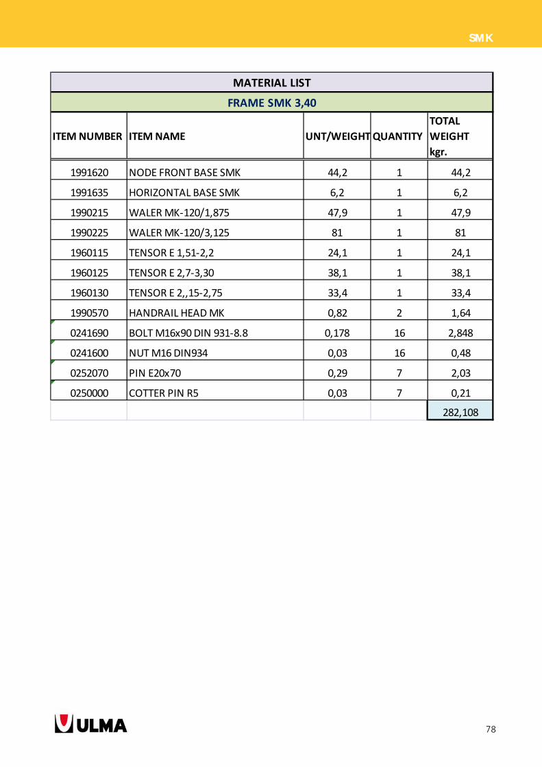
8.1. MATERIAL LIST
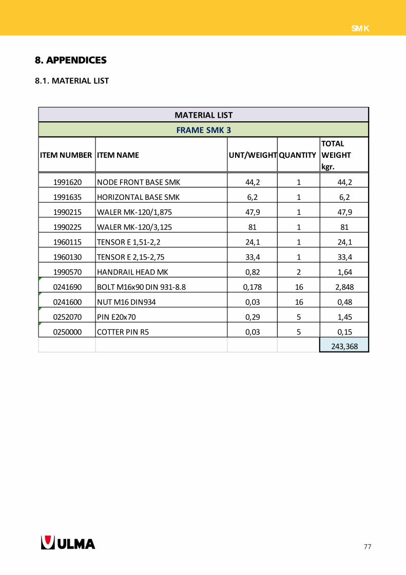
ITEM NUMBER ITEM NAME UNT/WEIGHTQUANTITY
TOTAL
WEIGHT
kgr.
1991620 NODE FRONT BASE SMK 44,2 1 44,2
1991635 HORIZONTAL BASE SMK 6,2 1 6,2
1990215 WALER MK‐120/1,875 47,9 1 47,9
1990225 WALER MK‐120/3,125 81 1 81
1960115 TENSOR E 1,51‐2,2 24,1 1 24,1
1960130 TENSOR E 2,15‐2,75 33,4 1 33,4
1990570 HANDRAIL HEAD MK 0,82 2 1,64
0241690 BOLT M16x90 DIN 931‐8.8 0,178 16 2,848
0241600 NUT M16 DIN934 0,03 16 0,48
0252070 PIN E20x70 0,29 5 1,45
0250000 COTTER PIN R5 0,03 5 0,15
243,368
MATERIAL LIST
FRAME SMK 3
78
SMK
ITEM NUMBER ITEM NAME UNT/WEIGHTQUANTITY
TOTAL
WEIGHT
kgr.
1991620 NODE FRONT BASE SMK 44,2 1 44,2
1991635 HORIZONTAL BASE SMK 6,2 1 6,2
1990215 WALER MK‐120/1,875 47,9 1 47,9
1990225 WALER MK‐120/3,125 81 1 81
1960115 TENSOR E 1,51‐2,2 24,1 1 24,1
1960125 TENSOR E 2,7‐3,30 38,1 1 38,1
1960130 TENSOR E 2,,15‐2,75 33,4 1 33,4
1990570 HANDRAIL HEAD MK 0,82 2 1,64
0241690 BOLT M16x90 DIN 931‐8.8 0,178 16 2,848
0241600 NUT M16 DIN934 0,03 16 0,48
0252070 PIN E20x70 0,29 7 2,03
0250000 COTTER PIN R5 0,03 7 0,21
282,108
FRAME SMK 3,40
MATERIAL LIST
79
SMK
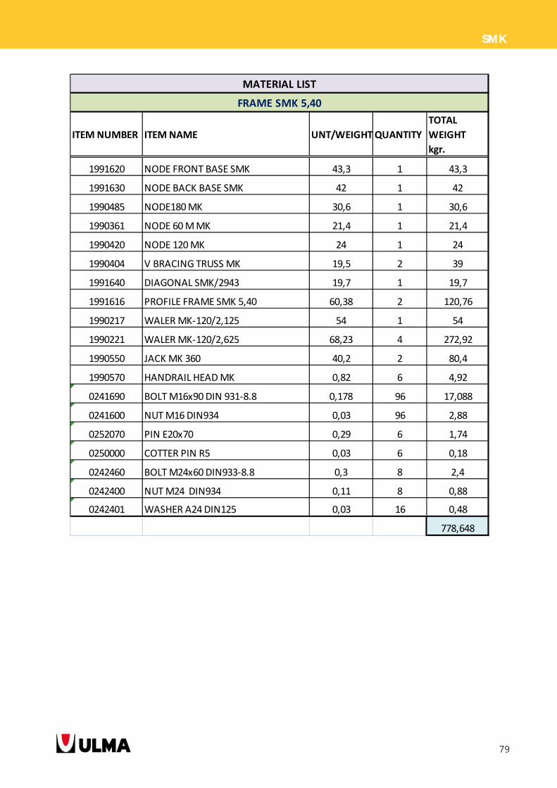
ITEM NUMBER ITEM NAME UNT/WEIGHTQUANTITY
TOTAL
WEIGHT
kgr.
1991620 NODE FRONT BASE SMK 43,3 1 43,3
1991630 NODE BACK BASE SMK 42 1 42
1990485 NODE180 MK 30,6 1 30,6
1990361 NODE 60 M MK 21,4 1 21,4
1990420 NODE 120 MK 24 1 24
1990404 V BRACING TRUSS MK 19,5 2 39
1991640 DIAGONAL SMK/2943 19,7 1 19,7
1991616 PROFILE FRAME SMK 5,40 60,38 2 120,76
1990217 WALER MK‐120/2,125 54 1 54
1990221 WALER MK‐120/2,625 68,23 4 272,92
1990550 JACK MK 360 40,2 2 80,4
1990570 HANDRAIL HEAD MK 0,82 6 4,92
0241690 BOLT M16x90 DIN 931‐8.8 0,178 96 17,088
0241600 NUT M16 DIN934 0,03 96 2,88
0252070 PIN E20x70 0,29 6 1,74
0250000 COTTER PIN R5 0,03 6 0,18
0242460 BOLT M24x60 DIN933‐8.8 0,3 8 2,4
0242400 NUT M24 DIN934 0,11 8 0,88
0242401 WASHER A24 DIN125 0,03 16 0,48
778,648
FRAME SMK 5,40
MATERIAL LIST
80
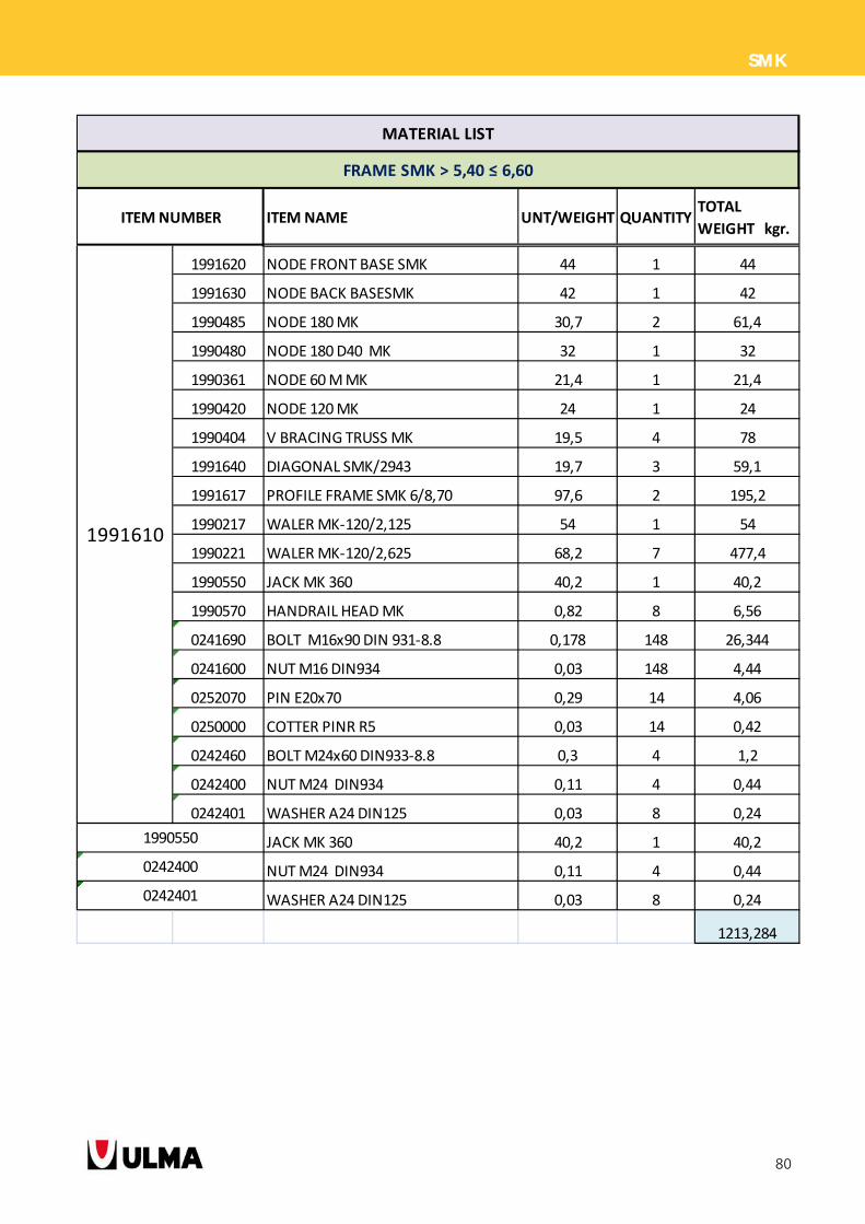
SMK
ITEM NAME UNT/WEIGHT QUANTITYTOTAL
WEIGHT kgr.
1991620 NODE FRONT BASE SMK 44 1 44
1991630 NODE BACK BASESMK 42 1 42
1990485 NODE 180 MK 30,7 2 61,4
1990480 NODE 180 D40 MK 32 1 32
1990361 NODE 60 M MK 21,4 1 21,4
1990420 NODE 120 MK 24 1 24
1990404 V BRACING TRUSS MK 19,5 4 78
1991640 DIAGONAL SMK/2943 19,7 3 59,1
1991617 PROFILE FRAME SMK 6/8,70 97,6 2 195,2
1990217 WALER MK‐120/2,125 54 1 54
1990221 WALER MK‐120/2,625 68,2 7 477,4
1990550 JACK MK 360 40,2 1 40,2
1990570 HANDRAIL HEAD MK 0,82 8 6,56
0241690 BOLT M16x90 DIN 931‐8.8 0,178 148 26,344
0241600 NUT M16 DIN934 0,03 148 4,44
0252070 PIN E20x70 0,29 14 4,06
0250000 COTTER PINR R5 0,03 14 0,42
0242460 BOLT M24x60 DIN933‐8.8 0,3 4 1,2
0242400 NUT M24 DIN934 0,11 4 0,44
0242401 WASHER A24 DIN125 0,03 8 0,24
JACK MK 360 40,2 1 40,2
NUT M24 DIN934 0,11 4 0,44
WASHER A24 DIN125 0,03 8 0,24
1213,284
0242400
0242401
MATERIAL LIST
FRAME SMK > 5,40 ≤ 6,60
ITEM NUMBER
1991610
1990550
81
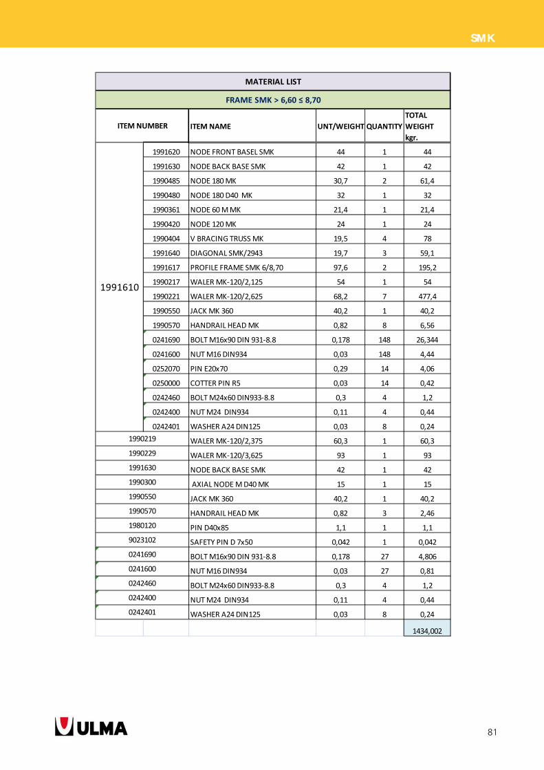
SMK
ITEM NAME UNT/WEIGHT QUANTITY
TOTAL
WEIGHT
kgr.
1991620 NODE FRONT BASEL SMK 44 1 44
1991630 NODE BACK BASE SMK 42 1 42
1990485 NODE 180 MK 30,7 2 61,4
1990480 NODE 180 D40 MK 32 1 32
1990361 NODE 60 M MK 21,4 1 21,4
1990420 NODE 120 MK 24 1 24
1990404 V BRACING TRUSS MK 19,5 4 78
1991640 DIAGONAL SMK/2943 19,7 3 59,1
1991617 PROFILE FRAME SMK 6/8,70 97,6 2 195,2
1990217 WALER MK‐120/2,125 54 1 54
1990221 WALER MK‐120/2,625 68,2 7 477,4
1990550 JACK MK 360 40,2 1 40,2
1990570 HANDRAIL HEAD MK 0,82 8 6,56
0241690 BOLT M16x90 DIN 931‐8.8 0,178 148 26,344
0241600 NUT M16 DIN934 0,03 148 4,44
0252070 PIN E20x70 0,29 14 4,06
0250000 COTTER PIN R5 0,03 14 0,42
0242460 BOLT M24x60 DIN933‐8.8 0,3 4 1,2
0242400 NUT M24 DIN934 0,11 4 0,44
0242401 WASHER A24 DIN125 0,03 8 0,24
WALER MK‐120/2,375 60,3 1 60,3
WALER MK‐120/3,625 93 1 93
NODE BACK BASE SMK 42 1 42
AXIAL NODE M D40 MK 15 1 15
JACK MK 360 40,2 1 40,2
HANDRAIL HEAD MK 0,82 3 2,46
PIN D40x85 1,1 1 1,1
SAFETY PIN D 7x50 0,042 1 0,042
BOLT M16x90 DIN 931‐8.8 0,178 27 4,806
NUT M16 DIN934 0,03 27 0,81
BOLT M24x60 DIN933‐8.8 0,3 4 1,2
NUT M24 DIN934 0,11 4 0,44
WASHER A24 DIN125 0,03 8 0,24
1434,002
MATERIAL LIST
FRAME SMK > 6,60 ≤ 8,70
ITEM NUMBER
1991610
1990219
1990229
1991630
1990300
0242460
0242400
0242401
1990550
1980120
9023102
0241690
0241600
1990570
82
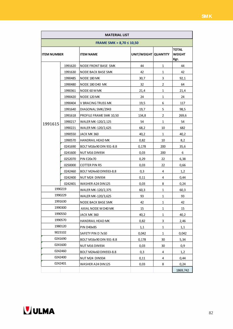
SMK
ITEM NAME UNIT/WEIGHT QUANTITY
TOTAL
WEIGHT
Kgr.
1991620 NODE FRONT BASE SMK 44 1 44
1991630 NODE BACK BASE SMK 42 1 42
1990485 NODE 180 MK 30,7 3 92,1
1990480 NODE 180 D40 MK 32 2 64
1990361 NODE 60 M MK 21,4 1 21,4
1990420 NODE 120 MK 24 1 24
1990404 V BRACING TRUSS MK 19,5 6 117
1991640 DIAGONAL SMK/2943 19,7 5 98,5
1991618 PROFILE FRAME SMK 10,50 134,8 2 269,6
1990217 WALER MK‐120/2,125 54 1 54
1990221 WALER MK‐120/2,625 68,2 10 682
1990550 JACK MK 360 40,2 1 40,2
1990570 HANDRAIL HEAD MK 0,82 10 8,2
0241690 BOLT M16x90 DIN 931‐8.8 0,178 200 35,6
0241600 NUT M16 DIN934 0,03 200 6
0252070 PIN E20x70 0,29 22 6,38
0250000 COTTER PIN R5 0,03 22 0,66
0242460 BOLT M24x60 DIN933‐8.8 0,3 4 1,2
0242400 NUT M24 DIN934 0,11 4 0,44
0242401 WASHER A24 DIN125 0,03 8 0,24
WALER MK‐120/2,375 60,3 1 60,3
WALER MK‐120/3,625 93 1 93
NODE BACK BASE SMK 42 1 42
AXIAL NODE M D40 MK 15 1 15
JACK MK 360 40,2 1 40,2
HANDRAIL HEAD MK 0,82 3 2,46
PIN D40x85 1,1 1 1,1
SAFETY PIN D 7x50 0,042 1 0,042
BOLT M16x90 DIN 931‐8.8 0,178 30 5,34
NUT M16 DIN934 0,03 30 0,9
BOLT M24x60 DIN933‐8.8 0,3 4 1,2
NUT M24 DIN934 0,11 4 0,44
WASHER A24 DIN125 0,03 8 0,24
1869,742
MATERIAL LIST
FRAME SMK > 8,70 ≤ 10,50
ITEM NUMBER
1991615
1990219
1990229
1991630
1990300
0242460
0242400
0242401
1990550
1980120
9023102
0241690
0241600
1990570
83
SMK
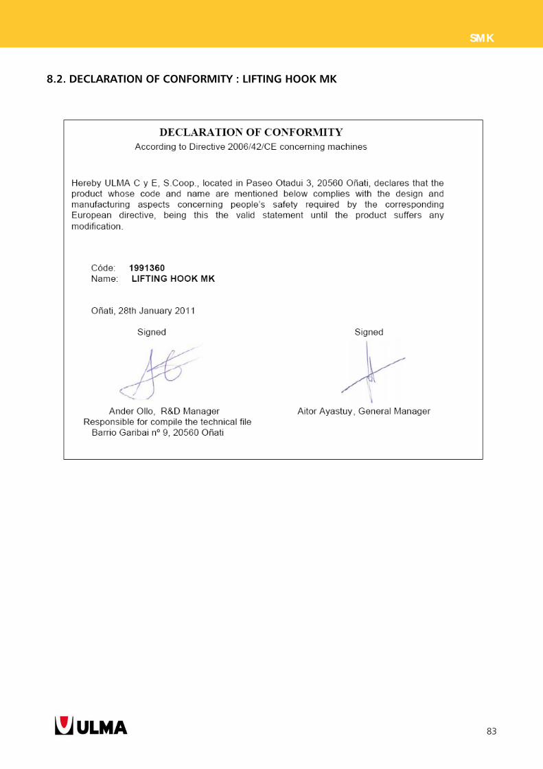
8.2. DECLARATION OF CONFORMITY : LIFTING HOOK MK
Canada
ULMA Construction SystemsCanada Inc.BOLTON - Ontariowww.ulma-c.ca
USA
ULMA Form Works, Inc.HAWTHORNE - New Jerseywww.ulma-c.us
West Branch (Phoenix)GILBERT - Arizona
Mid-Atlantic Branch(Baltimore) JESSUP - Maryland
Mexico
ULMA Cimbras y Andamiosde México S.A. de C.V.TLALNEPANTLA(Mexico State)www.ulma-c.com.mx
Peru
ULMA Encofrados Perú, S.A.LIMAwww.ulma-c.com.pe
North BranchCHICLAYO - Lambayeque
ASIA-AFRICA P.R. China
ULMA Formworks China R.O.SHANGHAIwww.ulma-c.cn
UAE
ULMA Formworks UAE L.L.C.DUBAIwww.ulma-c.ae
India
ULMA FORMWORKSYSTEMS INDIA PVT. LTD.GURGAON - Haryanawww.ulma-c.in
Mumbai BranchMUMBAI - Maharashtra
Kazakhstan
ULMA Formwork Kazakhstan Ltd.ASTANAwww.ulma-c.kz
Singapore
ULMA Formwork SingaporePTE. LTD.SINGAPOREwww.ulma-c.sg
Slovac Republic
ULMA Construccion SK, s.r.o.BRATISLAVAwww.ulma-c.sk
Romania ULMA Cofraje s.r.l.BUCHARESTwww.ulma-c.ro
Ukraine
ULMA Formwork Ukraine Ltd.KIEVwww.ulma-c.com
Dniepropetrovsk BranchDNIEPROPETROVSK
Odessa BranchODESSA
AMERICA Argentina
ULMA Andamios yEncofrados Argentina, S.A. FEDERAL CAPITALwww.ulma-c.com.ar
Brazil
ULMA Brasil - Fôrmas eEscoramentos Ltda.ITAPEVI - SPwww.ulma-c.com.br
Rio de Janeiro BranchANIL - Rio de Janeiro - RJ
Brasilia BranchGUARÁ - Brasília DF
Bahia BranchCIA SUL - Simões Filho
South BranchNAVEGANTES - Porto Alegre RS
Minas Gerais Branch
FUNCIONÁRIOS - Belo Horizonte
Chile
ULMA Chile - Andamios yMoldajes, S.A.SANTIAGOwww.ulma-c.cl
North BranchANTOFAGASTASouth BranchCONCEPCIÓN
Poland
ULMA contruccion Polska S.A.
WARSAW
www.ulma-c.pl
EAST REGION
Warsaw Branch
WARSAW
Olsztyn Branch
OLSZTYN
Łódź Branch
ŁÓDŹ
POZNAŃ BRANCH
Poznań Office
POZNAŃ
Bydgoszcz Office
BYDGOSZCZ
GDAŃSK BRANCH
Gdańsk Office
GDAŃSK
Szczecin Office
SZCZECIN
WROCŁAW BRANCH
Wrcoław Office
WRCOŁAW
Nowa Sól Office
NOWA SÓL
SOUTH REGION
Katowice Branch
JAWORZNO
Cracow Branch
CRACOW
Lublin Branch
LUBLIN
SCAFFOLDINGS BRANCH
Warsaw Office
WARSAW
Płock Office
PŁOCK
Portugal
ULMA Portugal Lda.SÃO JOÃO DA TALHA - Lisbonwww.ulma-c.pt
Oporto BranchVILA NOVA DE GAIA - Oporto
Czech Republic
ULMA Construcción CZ, s.r.o.BENÁTKY NAD JIZEROUwww.ulma-c.cz
EUROPE Spain
ULMA C y E, S. Coop.
www.ulma-c.es
Canary Islands Branch
GÜIMAR (Tenerife)INGENIO (Las Palmas)
Centre Branch
AJOFRÍN (Toledo)
East Branch
POLINYA (Barcelona)LLUCMAJOR (Baleares)
North Branch
LEGUTIANO (Álava)
West BranchCAMBRE (A Coruña)
South BranchPELIGROS (Granada)
Germany
ULMA Betonschalungen und Gerüste GmbH RÖDERMARKwww.ulma-c.de
Northwest BranchNEUSS
Southwest BranchGÖPPINGEN
East BranchARNSTADT
France
ULMA, S.A.R.L.BONDOUFLEwww.ulma-c.fr
Paris Region Branch BONDOUFLE
Eguilles BranchEGUILLES
Lille BranchLA CHAPELLE D’ARMENTIÈRES
Pau / Lons BranchLONS
Tarnos BranchTARNOS
Italy
ULMA Construction S.p.A.MONGUELFO - WELSBERG (BZ)www.ulma-c.it
Verona BranchS. MARTINO B.A. (VR)
PRODUCTION PLANTAND HEADQUARTERS
ULMA C y E, S. Coop.
Ps. Otadui, 3 - P.O. Box 1320560 OÑATI (Gipuzkoa)SPAIN
Phone: +34 943 034900Fax: +34 943 034920
www.ulma-c.comSPAINPhone: +34 943 034900Fax: +34 943 034920www.ulma-c.com