single shot phase shifting interferometry based on ...biblioteca.cio.mx/tesis/15949.pdf · i v...
TRANSCRIPT

i
v
Single Shot Phase Shifting Interferometry based on Polarization
Techniques
David Ignacio Serrano García
Submitted for the degree of Doctor of Science (Optics)
May 2014
León, Guanajuato, México.
March 2014

Single Shot Phase Shifting Interferometry based on Polarization Techniques
MSc. David Ignacio Serrano García Centro de Investigaciones en Óptica A.C.
Date:_______________________ Approved:
___________________________ Dr. Amalia Martínez García, Advisor
Centro de Investigaciones en Óptica A.C. León, Gto, México.
___________________________ Dr. Noel Iván Toto Arellano, Co-Advisor Universidad Tecnológica de Tulancingo
Tulancingo, Hidalgo, México.
Thesis submitted in partial fulfillment of the requirements for the degree of Doctor
of Science (Optics) at Centro de Investigaciones en Óptica A. C. León, Guanajuato, México. March 2014

Copyright by David Ignacio Serrano García
2014

I
Abstract
Phase-shifting interferometry techniques (PSI) require several phase-shifted
interferograms to retrieve the optical phase information of the sample. This task has been
usually performed by stages with great success, but presents the inconvenient of requiring a
series of sequential shots of the object under study. Time-varying phase distributions are
excluded from this schema and a single-shot PSI technique needs to be used. The most
common single-shot PSI technique is based on polarization principles to modulate the phase-
shift of the interferograms. The aim of this thesis is to present novel interferometric
configurations based on polarization phase shifting techniques.
Theoretical considerations for the polarization-interferometric properties are used to
successfully analyze dynamically phase changes in time varying samples. This approach has
given birth to several advanced interferometric systems applied to common path
configurations, slope phase measurements, temperature profiles and also proposes new
configurations. Experimental results for dynamic and static transparent samples are presented.

II
Acknowledgements
I would like to express my deep gratitude to Prof. Amalia Martínez for giving me the
opportunity to do the PhD under her esteemed guidance. My sincere thanks are due to her for
providing me freedom and opportunities to expand my research horizons.
I also would like to express my deep gratitude to Prof. Noel Iván Toto Arellano; his
encouragement played a crucial role in accomplishing the objectives that we had set for this
thesis. I am also grateful to his family members Mrs. Patricia and Damian for their moral
support.
I would like to thank the Mexican Science Council (CONACYT) for supporting me
with a PhD. scholarship for the period 2011-2014. This research was supported by
CONACYT under grant 180449.
I take this opportunity to thank Prof. Yukitoshi Otani for the support and guidance
provided during my stay at The Center for Optical & Research and Education in Utsunomiya
University in Japan.
I am grateful to my parents, brothers, and my wife Geliztle for everything that I may
have attained in my life.

III
Contents Introduction ....................................................................................................................... 1
Thesis Objectives .......................................................................................................... 3
Outline of the Thesis ..................................................................................................... 3
1. Single Shot Phase Shifting Interferometry ............................................................... 5
1.1 Polarization Phase Shifting Techniques........................................................... 7
1.2 Interference Pattern Replication ....................................................................... 9
Pattern Replication using Amplitude Gratings ................................................10
Pattern Replication using Phase Gratings ........................................................13
1.3 Conclusion ...................................................................................................... 14
2. 4D Phase Profiles based on a quasi-common path configuration ......................... 15
2.1 Phase Grating Interferometry .......................................................................... 16
2.2 Phase shifting interferometry with modulation of polarization ...................... 18
2.3 Experimental Setup ......................................................................................... 20
2.4 Experimental Results: Static and Dynamic Distributions ............................... 21
2.5 Conclusion ...................................................................................................... 24
3. Slope Phase Measurements Interferometers .......................................................... 25
3.1 Lateral Shear Interferometry ......................................................................... 25
3.2 Radial Shear Interferometry .......................................................................... 27
3.3 Cyclic Path Shearing Interferometer for Generation of Lateral and Radial
Shear ..................................................................................................................... 28
3.4 Mach-Zehnder Radial Shear Interferometer ................................................... 31
3.5 Conclusion ...................................................................................................... 34
4. Dynamic Temperature Profile Measurements ....................................................... 35
4.1 Temperature field measurement ..................................................................... 36
4.2 Experimental Setup ......................................................................................... 37
4.3 Conclusion ...................................................................................................... 41

IV
5. Single Shot Phase Shifting Interferometry using a Two-Interferograms
Phase Shifting Algorithm ......................................................................................... 43
5.1 Polarization Phase Shifting using Two-Interferograms .................................. 44
5.2 Experimental Results ...................................................................................... 46
5.3 Conclusion ...................................................................................................... 47
6. Dynamic birefringence mapping by a polarization image sensor ........................ 49
6.1 Experimental Results ...................................................................................... 52
6.2 Conclusion ...................................................................................................... 54
Conclusions and Future Work ....................................................................................... 55
References ........................................................................................................................ 59
Published Articles ........................................................................................................... 65

1
Introduction
Optical measurement techniques have become indispensable tools in many areas of
science and engineering. The whole-field, non-contact and highly accurate measurement
capabilities are among the principal features of these techniques. These techniques encode
the information on the measure in the phase of a two-dimensional fringe pattern; several
phase shifted replicas of this fringe pattern are used for retrieve information of the sample.
Phase shifting techniques are often used in optical interferometry1, fringe projection
profilometry2,3, digital holography1,4, electronic speckle pattern interferometry and
shearography5,6 because they allow to analyze samples using non-contact techniques with
high accuracy. The use of phase shifting modulated by polarization has the advantage of not
requiring mechanical components, such as a piezoelectric transducer (PZT), to obtain the
phase shifts, since it decreases the sensitivity of the system against external vibrations. A
common optical system uses linear polarizing filters and birefringent quarter-wave plates to
achieve modulation7,8.
The main purpose of Dynamic Phase-Shifting Interferometry (DPSI) is to collect all
the phase-shifted data in a single exposure in order to minimize time-varying environmental
effects. Since the data are collected simultaneously, the effects of vibration and turbulence
are greatly reduced.
Some DPSI systems achieve the simultaneous capture of several interferograms by
means of polarization, such as through the use of micro-polarizer array elements9, a point
diffraction interferometer10, a two-window phase grating interferometer11, as well as through
the use of a liquid-crystal spatial modulator12, among others. These systems have been
employed in several fields of application13,14.
Single shot polarization phase shifting techniques are currently a focus field of study,
the most important and an industry standard nowadays are the pixelated phase mask (PPM)
interferometers. One of the properties of these systems is that the modulating phase-mask

2
remains fixed, this placed before the CCD light sensor15. Some authors nowadays presents
novel algorithms based on these limitations, for example in the demodulation form,
algorithms focused on harmonic rejections and recently encountered a more accuracy results
by proposing an extension of the phase-shifting unit cell16,17.
The heart of the PPM interferometry systems lies in a pixelated phase-mask where
each pixel has a unique phase-shift. A small number of discrete steps (usually 4) can be
arranged into a “unit cell” which is then repeated contiguously over the entire array. The unit
cell can be thought as a super-pixel; the phase across the unit cell is assumed to have the
same value. Figure 0.1 illustrates a unit cell comprised of four discrete phase steps. The
overall system consists of a polarization interferometer that generates a reference wavefront
R and a test wavefront T having orthogonal polarization states (which can be linear or
circular) with respect to each other. The pixelated phase-mask (PPM) and the detector array
may be located in the same image plane, or positioned in conjugated image planes of the
PPM and the detector array. For example, the PPM located at the output of the polarization
interferometer and then an imaging system in charge to re-image the light transmitted
through the PPM onto the detector array.18
Figure 0.1 Basic concept of the pixelated phase mask interferometer.

3
Alternative systems, based on phase shifting polarization techniques, have been
presented before19. These systems can obtain interference replicas by using phase/amplitude
gratings20,21 but can retrieve only the phase data map.
In this research, several single shot phase shifting interferometers are proposed taking
into account the interferometric and polarization phase shifting properties in order to present
some alternatives to the PPM interferometer.
Thesis Objectives
1. Present the theoretical background used for single shot phase shifting interferometers
starting from the polarization properties through the Jones Calculation approach and
ending with the interferometric replication involved using a 4-f system with a
phase/amplitude grating in its Fourier plane.
2. Propose several interferometric systems in order to follow the 4D profiles of phase
objects. Configurations based on retrieving the slope of the phase directly; dynamic
temperature field measurements and configurations avoiding the use of the 4-f system
with phase/amplitude gratings are proposed.
Outline of the Thesis
Chapter 1 introduces the concepts of single shot phase shifting interferometry
techniques based on polarization modulation and interference replication using a 4-f system
with phase/amplitude grating.
Chapter 2 introduces a quasi-common path interferometer based on the interference
between replicas of the reference and object beams. The system geometry itself takes into
account the separation of the input beams and also the corrections involved in the usage of
polarization components that works at different wavelength than the light source used.
Chapter 3 presents a system capable of retrieving the slope phase object directly.
Chapter 4 is focused on analyzing the temporal temperature variation of a thin-flame
implementing new calibration and fringe processing techniques.

4
Chapter 5 is to propose a configuration that avoids the usage of a 4-f system with a
grating in the Fourier plane as a replication system. The system considers the two-
interferograms output of a polarization Mach-Zehnder interferometer.
Chapter 6 shows an implementation related to birefringence mapping using a
pixelated phase mask camera.
The final part of the thesis presents the summary, conclusions and future work.

5
Chapter 1
Single Shot Phase Shifting Interferometry
Single shot phase shifting interferometer that uses polarization phase shifting
techniques have three main characteristics in common:
1) The interferometer needs the reference and the object beams to have orthogonally
linearly polarization states between them.22
2) The polarization phase shifting is controlled by the angle of polarization
components (by using a linear polarizer or a half-wave plate, HWP)23–26.
3) The interferograms replication system which assesses the phase shifted
interferograms in the image plane.10,19,8
The first consideration can be achieved by taking into account the polarization
properties of the implemented interferometer. For simplicity the Jones calculus approach will
be used to follow the polarizing state in each stage of the interferometer. Figure 1.1 presents
a Polarizing Mach-Zehnder (PMZ) interferometer fulfilling this condition.
At the entrance of the interferometer a half-wave retarder and a linear polarizer at 45°,
, are used to have a 45° linearly polarized input beam,
√ ( ) . Taking the
polarizing beam splitter (PBS) as a linear polarizer at 0° and 90° for the transmitted and
reflected part, the output state of the PMZ:
,
√ ( )
√ (
)
1.1

6
Figure 1.1 Polarizing Mach-Zehnder (PMZ) interferometer.
where and represents the state corresponding to the reference and object beams:
[
] [
] [
]
[
] [
] [
] . 1.2
By assuming , . It is important to note that the transparent sample
is treated only as a phase object. For a more rigorous treatment, the Jones matrix of the
sample need to be taken into account and polarization compensation components need to be
placed on the reference beam.
For a correct implementation of the system and to avoid the use of more specialized
polarization components, double reflection and transmission of the beams is carried out. To
do this, Figure 1.2 presents two common interferometry configurations: a cyclic path
shearing interferometer and a Michelson interferometer fulfilling this condition to apply the
polarization phase shifting conditions.

7
Figure 1.2 Cyclic path shearing interferometer and a Michelson interferometer employing polarization.
1.1 Polarization Phase Shifting Techniques
It is often useful to be able to shift the location of the fringes when displaying an
interferogram. In conventional interferometry, we move the fringes by changing the relative
phase between the interfering waves23. The most common system is the use of a piezoelectric
transducer (PZT) which translates a mirror perpendicularly to its surface. There also exists
another class of fringe shifter employing polarization techniques. The most common
techniques are based on controlling the phase shift by rotating polarization components such
as linear polarizers or half-wave retarders placed at the output of the interferometer whose
reference and object beams have orthogonal linear polarization states.
Figure 1.3 shows a diagram of the phase shifter that could be used at the exit of an
interferometer where the reference and test beams have orthogonal linear polarization. A
quarter-wave plate converts one of the two interfering beams into right-handed circularly
polarized beam and the second interfering beam into a left-handed circularly polarized beam.
As a polarizer is rotated an angle the phase difference between the test and reference beams
changes by . The polarizer also makes it possible for the two beams to interfere. The
output polarization state of a beam, after passing through a linear polarizer at angle , can be
obtained as:
[
]
√ [
] [
].
1.3

8
Its corresponding intensity will results in the well-known interferogram equation with a
controlled phase shift twice the angle of the polarizer,
‖ ‖ [ ], 1.4 Figure 1.4 presents a polarization Mach-Zehnder (PMZ) interferometer as an example.
Figure 1.3 Polarization phase shifter controlled by the angle of the linear polarizer.
Figure 1.4 Mach-Zehnder interferometer where the phase shift is controlled by the angle of the linear polarizer, , placed at the exit of the interferometer
45QWPLP
HWPLP
),( yx

9
An alternative polarization phase shift system is implemented by changing the angle
of a half-wave plate placed between two quarter wave plates and a fixed polarizer at the exit
of the interferometer. In this case the phase shift introduced will be fourth times the angle of
the half-wave plate 22,24
1.2 Interference Pattern Replication
When the interferometer is coupled to a 4-f system using phase grids or Bi-Ronchi
gratings, it is possible to obtain replicas of the interference pattern. Each of these replicas can
be modulated by polarization. Figure 1.5 represents a schematic diagram of the 4-f system
with a grating placed in the frequency plane in order to get replicas of the input
polarization state . In this case the linear polarizer LP is placed on each of
the replicas obtained.
Figure 1.5 Replication system composed by a 4-f system with a grating ),( G placed in the frequency plane in order to get replicas of the input polarization state.
The output interferogram, , will corresponds to the convolution of the diffraction
pattern of the grating, , with the interefrogram, ,
| |; 1.5 depending of the characteristics of the grating, certain properties will be encountered in the
replicated interferogram. In this work we used amplitude (Ronchi Ruling) and phase gratings
commercially available27,28.
f f),( G
RefObjTot JJJ
LP

10
For explanation purposes, the case with a sinusoidal amplitude grating will be
discussed. Its complex amplitude is:
[ ]
,
1.6
with being the grating contrast and with d as the grating period. Its
corresponding Fourier transform is given by
, 1.7
with as the two-dimensional Dirac delta function. By taking eq. 1.5:
|
|
.
1.8
Thus, at the image plane of the 4-f system three replicas of the interferogram will be
encountered.
Pattern Replication using Amplitude Gratings
In general, when Bi-Ronchi gratings are placed in the Fourier plane, they can be
considered to be the multiplication of two cross amplitude Ronchi gratings19,
L
Ll w
N
Nn w adlrect
adn
rectGGG
)()(),( , 1.9
where N, L are the numbers of components of the grating, d , d are the respective periods
along directions “ ” and “ ”, and wa , wa are the widths of the light part of the strips
along each direction. The gratings studied have equal periods in both directions; then,
ddd , so www aaa . Due to the convolution properties of the Fourier transform30,
the corresponding spectrum is:

11
L
Llyl
N
Nnxn
L
Ll
wN
Nn
ww
dlyC
dnxC
dlyy
da
dnxx
da
da
yGxGyxG
sinc sinc
)(~)(~),(~
2
2
, 1.10
with
x
da
daC ww
xn sinc and
y
da
daC ww
yl sinc .
For the experimental case where gratings have the same period, mmd 01.0 , the
diffraction patterns generated, using Eq. 1.10, are shown in Figure 1.6. Figure 1.6(a) shows
the simulated diffraction pattern generated by the Bi-Ronchi grating. In Figure 1.6(b), it can
be seen that the amplitude spectra for each axis shows more than three orders of diffraction;
however, only orders 0 and ±1 allow one to obtain replicas of the interference pattern with
comparable intensities.
Figure 1.6 Simulated diffraction pattern generated by high frequency Bi-Ronchi gratings. (a) Diffraction spectra. (B) x-y components of diffraction spectra of each grating component.
The 4-f system with high frequency Bi-Ronchi gratings only multiplexes the
interference pattern generated at the output of interferometer; the phase shifts in the

12
interference pattern are managed only by linear polarizers placed at the output. Considering
Eq. 1.4 the interference pattern ),(' yxI on the image plane of the system is
2
2
),(~),(
),(~),('
yxGyxI
yxGJJLPyxI
out
refObj
. 1.11
As in Eq. 1.3, each beam has circular polarization, LP represents the Jones matrix of the
linear polarizer at angle and ),( yxIout represents the interference pattern generated by the
interferometer. The resulting intensity captured by the camera is:
2),(cos1
-,- ),('
22
22
yxCC
dly
dnxICCyxI
N
Nnxn
L
Llyl
yx
N
Nnxn
L
Llyl
. 1.12
Equation 1.12 shows that the resulting intensity distribution consists of replicas of the
pattern generated by the interferometer displaced to the nth and lth orders of diffraction; each
replica of the main pattern maintains an intensity modulated by the Fourier coefficients Cn
and Cl corresponding to each direction. In this case the Ronchi gratings only multiplex the
pattern, so the amplitudes of the orders only increase or decrease the intensity of the
interference patterns, as it’s shown in Figure 1.7. Figure 1.7 shows the experimental results
obtained with a Bi-Ronchi grating. The interference patterns used, enclosed in a circle, with
independent phase shifts, can be generated by linear polarizers. Figure 1.7(a) shows the
diffraction orders distribution, indicated by two subscripts. Figure 1.7(b) shows the
diffraction orders generated by the grating; it can be seen that they have at least 4 diffraction
orders with comparable intensities. This result is due to the modulation generated by
coefficients Cn and Cl (see Eq. 1.12). Figure 1.7(c) shows the replicas of the interference
patterns centered on each diffraction order.

13
Figure 1.7 Replicas of the interference patterns. (a) Fourier coefficients for each replica of the interference pattern. (b) Experimental diffraction orders generated by high frequency Bi-Ronchi gratings (100 ln/mm). (c) Replicas of the interference patterns centered on each diffraction order (Circle).
Pattern Replication using Phase Gratings
A sinusoidal phase grid generated by multiplication of two sinusoidal phase gratings,
whose respective grating vectors are crossed, generates diffraction orders modulated by
Bessel functions Jq and Jr 21, and the image of the interference pattern generated by the
interferometer is found centered around each of them.
To draw theoretical conclusions, we assume that the phase grid is made up from two
phase gratings of modulation depth as gA2 each and with orthogonal gratings vectors. Taking
the rulings of one grating along the “ ” direction and the rulings of the second grating along
the “ ” direction, the resulting Fourier transform of the centered phase grid can be written
as:
q
q
r
rgrgq rXyqXxAJAJyxG 002 ,22,~ , 1.13
where the order separation is dfX /0 and qJ , rJ denotes the Bessel function of the first
kind and integer order q, r. In the image plane of the system, taking only the contribution of
an isolated term of order qr, the irradiance would be proportional to
q r
rqrq yxJJyxI 2),(cos12),(' 22 1.14

14
where a translation of coordinates was used around the order position ( 0qXxxq and
0rXyyr ). As before the obtained phase shift is twice the angle of the linear polarizer.31
The grid makes copies of both interfering beams, keeping their circular polarizations to be
detected through a linear polarizer array, where each of the linear polarizer is set at different
angle.
Figure 1.(a) shows the diffraction orders distribution, indicated by a subscript Jn,l,
generated by the phase grid. Figure 1.8(b) shows the diffraction orders obtained and it can be
seen that they have at least 9 diffraction orders with comparable intensities. This result is due
to the modulation generated by Bessel function Jn,l. Figure 1.8(c) shows the replicas of the
interference patterns obtained centered on each diffraction order.
Figure 1.8 Replicas of the interference patterns. (a) Fourier coefficients for each replica of the interference pattern. (b) Experimental diffraction orders generated by high frequency phase gratings (110 groves/mm). (c) Replicas of the interference patterns centered on each diffraction order (Circle).
1.3 Conclusion
Polarization phase shifting techniques requires several conditions that need to be met,
the most important is that the interferometer needs to have linear orthogonal polarization
states between the reference and object beams.
By using the 4-f system with gratings placed in the frequency plane, as a replication
system, an amplitude modulation is obtained in the image plane; this latter effect can be
compensated by using normalization procedures or by using replicas orders with almost the
same amplitudes.

15
Chapter 2
4D Phase Profiles based on a quasi-common path configuration
In this chapter, we propose a configuration of a two-window polarizing phase shifting
interferometer11,20,32, based on two coupled systems: a Mach-Zehnder interferometer(MZI)
that allows the two-window generation with adjustable separation, and a 4-f system with
phase gratings placed on the frequency plane.19,33 One advantage of these configurations is
that, when the beam separation is properly changed, interference of the different diffractions
orders can be obtained. The system is insensitive to external vibrations due to its quasi-
common path configuration. The previously presented two-window interferometer with
diffraction gratings33 was implemented using a fixed separation corresponding to the grid
used. In the proposed configuration, we can freely adjust these separation and positions.
Also, with the proposed optical system, we can obtain results of the same quality as those
obtained in previous reports20,33, in a more flexible system which is not limited by optical
components, such as the grid used.
To generate independent phase shifts in the interference patterns, a linear polarizer is
placed at a convenient angle on each replica8. In the experimental results presented, the
interference patterns are processed by means of two methods, for the case of four
interferograms and for the case of nine interferograms, using the symmetrical (N+1) nine
algorithm34.

16
2.1 Phase Grating Interferometry
Phase gratings have interesting properties, such as the advantage of using a higher
percentage of incident energy compared with absorption gratings. The advantage of using
cross-phase gratings is the ability to generate up to 16 replicas of the interferogram with
independent phase shifts. This allows the use of other algorithms to process the phase.
Furthermore, the use of cross-phase gratings allows obtaining π-phase shifts, figuring 2.1,
simplifying the polarizer arrangement. A phase grid, carefully constructed by means of
superposing two phase gratings with their respective grating vectors at 90 , is placed at the
system’s Fourier planes. Taking the rulings of one grating along the direction,
and the
rulings of the second grating along the
direction, the resulting centered phase grid can
be written as:
00
00
22
2sin22sin2
22
,
rXi
rgr
qXi
qgq
XAiXAi
eAJeAJ
eeG gg
, 2.1
where the frequencies along each axis direction are taken as 0X , with gA2 being the phase
grating amplitude, and Jq and Jr the Bessel functions of the first kind of integer order q, r,
respectively. The Fourier transform of the phase grid becomes
q
q
r
rgrgq rXyqXxAJAJyxG 00 ,22,~ , 2.2
which consists of point-like diffraction orders distributed on the image plane. Phase grid
interferometry is based on a two crossed phase grating placed as the pupil in a 4-f Fourier
optical system, figure 2.2. A convenient window pair for a grating interferometer implies an
amplitude transmittance given by
),2
(),2
(),( 00 yxxByxxAyxO , 2.3
where x0 is the separation from center to center between two beams, A(x, y) as the reference
beam aperture and B(x,y) is the beam aperture where the phase object is placed. Placing a

17
grating of spatial period 0/ Xfd at the Fourier plane, with a corresponding transmittance
given by ,G , Eq. 2.1. The image formed by the system consists basically of replications
of each window separated at distances 0X . This image is defined by yxO ,´ ; that is, the
convolution of yxO , with the Fourier transform of the phase grating, yxG ,~ represented
by
.,)2(,2
,)2(,2
,~),(),´(
0
),2
(0
00
0
yqXxAJeyxxw
yqXxAJyxxw
yxGyxOyxO
qgq
yx
xi
qgq
, 2.4
where (*) denotes the convolution. By adding the terms of Eq. 2.4, taking q and q-1 (both
located within the same replicated window
yxqXxw ,
20
0 ), and for the case of
matching the beams positions with the diffraction order’s positions ( 00 xX ), Eq. 2.4 can be
simplified as
q
yqxxi
gqgq yqxxweAJAJyxO ,21)2()2(),´( 0
),21(
1
0
. 2.5
Thus, an interference pattern between fields associated to each window must appear
within each replicated window. The fringe modulation mq of each pattern would be of the
form32
21
212
qqq JJ
JJm , 2.6
where each fringe contrast depends on the relative phases between the Bessel functions qJ .

18
2.2 Phase shifting interferometry with modulation of polarization
Turning the attention to gratings, in order to introduce additional phase shifts in the
interference pattern centered around yqx ,)2/1((0 , each of the windows is illuminated
with different polarizations using retarding plates QR and QL, Figure 2.2; this arrangement
introduces Jones polarization vectors RJ and LJ
into the interference terms of Eq. 2.4. After
placing a linear polarizing filter with the transmission axis at an angle , its irradiance turns
out to be proportional to:
)],()',(cos[2)',( 12
122 yxJJJJAJ qqqqT
, 2.7
where 1 qRl
qLl
T JJJJJJJ
, lJ is the transmission matrix for the linear polarizer at angle
, ' is the retardation of each plate, and )',( denotes the phase shifting term
induced by modulation of polarization given by
]'cos[]2sin[]'2cos[][sin][cos]'2sin[][sin]'sin[]2sin[)',( 22
2
ArcTan , 2.8
)',( A is defined as
]'cos[]2sin[1)',( A 2.9 denoting each pattern as
)],()',(cos[2)',( 12
122 yxJJJJAJ iqqqqi
2.10
with i = 1…N.
For phase-shifting interferometry with four patterns, four irradiances can be used,
each one taken at a different angle. The relative phase can be calculated as:34
24
22
23
21tan
JJ
JJ
, 2.11
where 21J
, 22J
, 23J
and 24J
are the intensity measurements with the values of such
that 2/3)(,)(,2/)(,0)( 4321 respectively. Note that 2)2/,(
and 1)2/,( A , so a good choice for the retarders is quarter-wave retarders, as it is well

19
known. Dependence of on the coordinates of the centered point has been simplified to x,y.
The same fringe modulation mq results, as in Eq. 2.6. Therefore, the discussion about fringe
modulation given in previous sections is retained when introducing the modulation of
polarization. Such polarization modulation can be carried out also for grids, resulting in
similar conclusions.
To demonstrate the use of the various interferograms obtained to extract phase under
the conditions described above, we choose the symmetrical N+1 phase steps algorithms for
data processing, the phase is given by34:
1
1
12cos
12sin,tan N
ii
N
ii
NiI
NiI
yx
, 2.12
where N+1 is the number of interferograms. For the case of nine interferograms, only five
linear polarizing filters have to be placed. The transmission axes of the filter pairs LPi can be
the same for each one, as long as they cover two patterns with π-phase shift in between.
Experimentally, the phase shifting obtained is the result of placing a linear polarizer
in each one of the interference patterns generated on each diffracting orders on the exit plane
( iP ); each polarizing filter transmission axis is adjusted at a different angle i , see Figure
2.1(a). The experimental observations suggest a simplification for the polarizing filter array
due to the π phase shift obtained; thus, it is not necessary to use all linear polarizing filters for
all patterns. For example, in the case of four steps, we only need to place two polarizers ( 0P
and 1P ), each one covering two patterns with complementary phase shifts; then, 00 and
577.46120, which leads to phase shifts of 0, ,2/,0 , and 2/3 , and can be seen in
Figure 2.1(b), with the dotted boxes representing the polarizing filters. This result allows us
to know the phase profile. Since n-interferograms can be obtained simultaneously, the
dynamic study of a phase objects can be carried out.

20
Figure 2.1 Replicas of the interference patterns obtained with the phase grid (a) Polarizing filters array. (b) Experimental interference patterns.
2.3 Experimental Setup
The optical system proposed is shown in Figure 2.2. It consists of a combination of a
quarter-wave plate Q and a linear polarizing filter P0 that generates linearly polarized light
oriented at 45 angle entering the Mach Zehnder configuration from a YVO3 laser operating
at 532 nm. This configuration generates two symmetrically displaced beams by moving
mirrors M and M’, enabling one to change spacing 0x between beam centers. Two retardation
plates (QL and QR), with mutually orthogonal fast axes, are placed in front of the two beams
(A, B) to generate left and right nearly-circular polarized light. A phase-grating
)/,/( fvfuG is placed on the frequency plane (u,v) of the 4-f Fourier optical system that
is coupled to the Mach Zehnder configuration. On plane ),( , the period of G is denoted by
d, and its spatial frequency by d/1 . Two neighboring diffraction orders have a
separation distance of dfX /0 at the image plane for a grating; the phase shifts caused by
the grating at the image plane of this system are discussed in9,20,35.

21
Figure 2.2 Experimental setup. BS: Beam splitter. PBS: Polarizing Beam splitter. O(x, y): Object plane. O´(x, y): Image plane. Li: Lens. Pi: Polarizer's. Grating period, d = 110 lines/mm. x0 = 10 mm. f = 150 mm. The transparent sample is located on B.
2.4 Experimental Results: Static and Dynamic Distributions
The phase gratings that were used are the commercially available ones (Edmund
Optics transmission grating, dimensions: 25x25mm; dimensional tolerance: 5.0 mm;
substrate: optical crown glass). The monochromatic camera used has a CMOS sensor with
1280 × 1024 pixels and with a pixel pitch of 6.7μm. Each interferogram was typically
composed of arrays of 600 × 512 pixels and then filtered with a conventional low-pass filter
to remove sharp edges and detail from the image, leaving smooth gradients and low-
frequency detail. To reduce differences of irradiance and fringe modulation, each
interferogram used was subjected to a rescaling and normalization process. This procedure
generates patterns of equal background and equal fringe modulation. There are several 2D
phase unwrapping algorithms; however for simplicity the method used for unwrapping the
phase data was a non-iterative fast cosine method36.
A phase dot generated with a magnesium fluoride film (MgF2) on a glass substrate
was placed in the path of beam B, while beam A was used as a reference; the results obtained
are shown in Figure 2.3. Figure 2.3(a) shows the four patterns with 2/ phase shifts
obtained in a single shot, and Figure 2.3(b) presents the phase profile of the object, in false
color coding. However, more than four interferograms could be used, whether for N-steps
phase-shifting interferometry or for averaging images with the same shift.

22
Figure 2.3 Phase dot prepared evaporating magnesium fluoride (MgF2) on a glass substrate: (a) Four 90° phase-shifted interferograms. (b) Phase profile.
Comparatively, the results obtained with the proposed optical system, are equal to
those obtained with interferometers double fixed window, however the implementation of
this optical system becomes simpler, since it is easier to place the necessary components and
also we are able to use phase grids with other periods, or absorption grids, only taking in
consideration the correct separation of the two windows.
To demonstrate the use of several interferograms, we choose the symmetrical
n=(N+1) phase steps algorithms34, for data processing (case N=8). A constant phase shift
value of N/2 is employed when using these techniques. The phase shifts of due to the
grid spectra allow the use of a number of polarizing filters that is less than the number of
interferograms, simplifying the filter array, Figure 2.4. According to Figure 2.4(b), it can be
shown that for symmetrical nine, 01 , 989.922 , 975.223 , 577.464 and
903.1575 . In this case, each resulting step corresponds to a 45° phase-shift.32 The
corresponding results and calculated phases are shown in Figure 2.5, the experimental results
shows the interference pattern and unwrapped phase generated by a tilted wavefront.
A dynamic phase object is shown in Figure 2.6. It corresponds to flowing oil on a
glass microscope slide allowing to flow under the effect of gravity. The phase object was put
in front of B windows of the system of Figure 2.2. For this case, four interferograms are used
to process the optical phase.

23
Figure 2.4 Interference patterns detected with a polarizing filter at 25 . (a)The interference patterns used are enclosed in the dotted rectangle. (b) Polarizer filter array for N=8, nine symmetrical interferograms.
Figure 2.5 Tilted wave-front. (a) Nine 45° phase-shifted interferograms (b) Unwrapped phase data map.

24
Figure 2.6 Dynamics distributions. Representative Frames. Evolution of the phase profile, one capture per 2 seconds.
2.5 Conclusion
The experimental set-up for an adjustable two windows interferometer based on a
Mach Zehnder configuration has been described to obtain the phase profile of phase objects
from the analysis of optical phase using polarizing phase shifting techniques. This system is
able to obtain N interferograms with only one shot ( 16n ).
Tests with four phase-shifts were presented, but also used other approaches using
different phase-shifts, attained using linear polarizers with their transmission axes at the
proper angle before detection (case of nine interferograms). The phase shifts of due to the
grid spectra allows the use of a number of polarizing filters which is less than the number of
interferograms, simplifying the filter array. The interferometric system allows the analysis of
static objects and dynamics objects.
The current system only showed the temporal evolution of an oil drop by gravity, as a
future work a system capable of following specific fluid properties (viscosity, density, etc.)
will be investigated.

25
Chapter 3
Slope Phase Measurements Interferometers
Two shearing interferometers were implemented to analyze the slope of phase objects
using simultaneous phase-shifting shearing interferometry37. These optical configurations
allow us to obtain n-shearograms simultaneously to retrieve the derivative of the optical
phase data map 37,38.
In the lateral shearing interferometers the same wavefront is superposed with its copy
but displaced a distance x . When x is sufficiently small, the phase difference can be
approximated as the directional derivative of the wavefront in the displacement direction39,40.
Lateral shear interferograms have different fields of applications like optical tests,
wavefront aberrations,41 phase singularities detection (optical vortex)42 and mechanical
stress43 among others. In the case of radial shear interferometers the superposition is
against the same wavefront at different scales (contracted or expanded) with no displacement.
The proposed systems presents the advantage of obtaining lateral and radial shear by using of
adequate components, both cases are studied and presented in this work.
Two shear interferometric systems were proposed: A cyclic path shearing
interferometer and a Mach–Zehnder Radial-Shear interferometer (MZRI). Phase grid placed
on a Fourier plane of a 4-f system was used as interferometric replication method.
3.1 Lateral Shear Interferometry
Defining the resultant vectorial beam amplitude of a Lateral Shear interferometer as
),2
('),2
(),( 001 yxxwJyxxwJyxt RL
, 3.1

26
where 0x is the mutual separation of the beams along x, w and w’ is the aperture of the beam
sheared by a distance 0x . LJ
and RJ
represents the Jones vectors for right and left circular
polarization as
iJ L
1,
iJ R
1. 3.2
Based on our replication method using phase gratings in a 4-f system, the two
mutually separated beams enters the 4-f system with cross linear polarization, after passing a
quarter-wave retarder )( 1Q , cross circular polarization states are obtained. The phase grid is
used to obtain replicated shearograms were each of one can be modulated by polarization to
obtain the desired phase shift. The lateral shear 0xs must be smaller than the transversal
section a of the beams, this implies that the lateral displacement is smaller than the
diffraction order separation defined as 0X .
To draw theoretical conclusions, we assume that the phase grid is made up of two
phase gratings (with 2πAg the grating’s phase amplitude) and with orthogonal gratings
vectors. The resulting Fourier transform of the centered phase grid can be written as:
q
q
r
rgrgq rXyqXxAJAJyxG ),()2()2(),( 00
~ . 3.3
On the image plane of the system the amplitude can be written as
q
q
r
rRLgrgq rXyxqXxwJrXyxqXxwJAJAJ
yxGyxtyxt
),2
('),2
()2()2(
),(),(),(
00
000
0
~
10
. 3.4
On the image plane of the system, a series of replicated beams can be observed. Because of
their polarization, an interference pattern can be detected by placing a linear polarizer filter
(rq
P, ) at angle ( rq, ) before the detector on each of the (q,r) replicas to be used. A single
fringe pattern is defined as 32
rqrqrq yxJJyxtPyxIrq
,(2cos12),(),( 222
0, ,
3.5

27
where a translation of coordinates was used around the order position ( 0qXxxq and
0rXxyr ), and ),2/(),2/(),( 00 yxxyxxyx . By analyzing Eq.3.5, it can be
noted that the phase shift obtained in the interferogram will be twice the angle of the linear
polarizer placed and each of the interferogram amplitude modulation will be dependent of the
(q,r) order used.
3.2 Radial Shear Interferometry
In this case the transversal sections of the beams can be described as:
),(
)/,/(
),('
),(
yxi
MyMxi
a
ecircyxw
eM
circyxw aa
, 3.6
where 22 yx and 12 / ffMa denotes the relative magnification of the pupils as the
focal lengths of both lenses (L1,L2), figure 3.4, for this case the resultant vectorial beam
amplitude of the Radial Shear-CSI entering the 4-f system is
)(')()(2
wJwJt RL , 3.7
representing cross circular polarization states of the same beam radially sheared. As it was
shown in the past section, in the image plane of the 4-f system the fringe pattern obtained is
modulated by the Bessel function as Eq. 3.5 but presenting radial symmetry,
rqrqrqrqrqrq yxJJyxtPyxIrq
,(2cos12),(),( ,22
2
0, ,
)/,/(),(),( araqrqrq MyMxyxyx 3.8
where a translation of coordinates was used around the order position ( 0qFxxq and
0rFxyr ), and )/,/(),(),( araqrqrq MyMxyxyx . In general, the interference
pattern can be described as:21
xyxyxByxAyxI ii),(2cos),(),(),(
3.9

28
for the case of lateral shear in x-direction. ),( yxIi represents the 4..1i intensity
distribution captured by the CCD camera in a single shot, the polarization filters angles are:
01 , 452 , 903 and 1354 , each of them represents phase shifts of 0 , 45 ,
90 and 135 respectively. By considering that ),( yxA and ),( yxB are constant the relative
phase change can be calculated as:34
),(),(),(),(arctan),(
42
31
yxIyxIyxIyxI
xyx 3.10
For the case of radial shear, Eq. 3.10 can be used only with the consideration of the radial
dependency.
3.3 Cyclic Path Shearing Interferometer for Generation of Lateral and Radial
Shear
Figure 3. shows the interferometers proposed for lateral shear and radial shear. The
two optical systems are capable of obtaining in a single shot four shearograms with
independent phase shifts. Figure 3.(a) shows the two possible interferometers that can be
coupled to the 4-f system, each of them is used separately to generate a specified shear, the
system-I is a Cyclic Shear Interferometer (CSI), where the shear is generated by moving the
mirror M by a small distance s . The system-II is a cyclic radial shear interferometer (CRI),
the optical setup is similar to the previously proposed, adding a pair of lens L1 and L2 to
obtain the two beams with different diameter in the transversal section. In this case also
lateral shear can be obtained only with a small displacement in M, resulting in a combination
of a lateral and radial shear interferometer. Figure 3.2(b) shows the plots representing the
superposition of amplitude spectra in the output of the two systems.
The system uses a He-Ne laser operating at λ=632.8nm. The collimated beam has a
transversal section of a=8.6mm and linear polarization state oriented to 45°± generated by a
quarter-wave retarder (Q0) and a linear polarizer (P0). By the use of a polarizing beam splitter
(PBS) the resulting beams have cross linear polarization and after passing the quarter wave
retarder (Q1), right and left circular polarization is obtained. The mirrors defined as M and M’
are used to introduce the lateral shear s . The 4-f system coupled to the cyclic interferometer

29
uses two equals lenses (f =20 cm) and a phase grid defined as ),( G placed in the posterior
focal plane of the first lens. The system’s pupil has a spatial period mmd110
1 . Replicated
beams of the interference pattern are obtained from this configuration. Placing a linear
polarizer on each replica, an independent phase-shift can be obtained. No extra corrections
were used in the angle of the linear polarizers used because the quarter wave retarders
),( 10 QQ operate at the wavelength of the source.
Figure 3.1 Cyclic Shearing interferometers with phase grid and modulation of polarization. (a) Configuration I is a variable lateral-shear interferometer were laterally sheared diffraction orders are superimpose (b-upper). Configuration II is a cyclic radial interferometer (CRI) were radially sheared diffraction order are superimpose (b-lower).
Lateral shear interferograms representing spherical aberration with defocusing are
shown in Figure 3.. The Figure 3.(a) presents the four patterns obtained simultaneously with
relative shifts of 2/ . Phase derivative in x-direction is presented in Figure 3.(b). Figure 3.3
presents experimental results corresponding of an oil drop located on a microscope slide. The
system may be used to measure the surface deformations in fluids and also measurement of
the concentration gradients of liquids.

30
Figure 3.2 Experimental results corresponding of a lateral shear representing spherical aberration with defocusing.
Figure 3.3 Experimental results corresponding of an oil drop located on a microscope slide.
31
3.4 Mach-Zehnder Radial Shear Interferometer
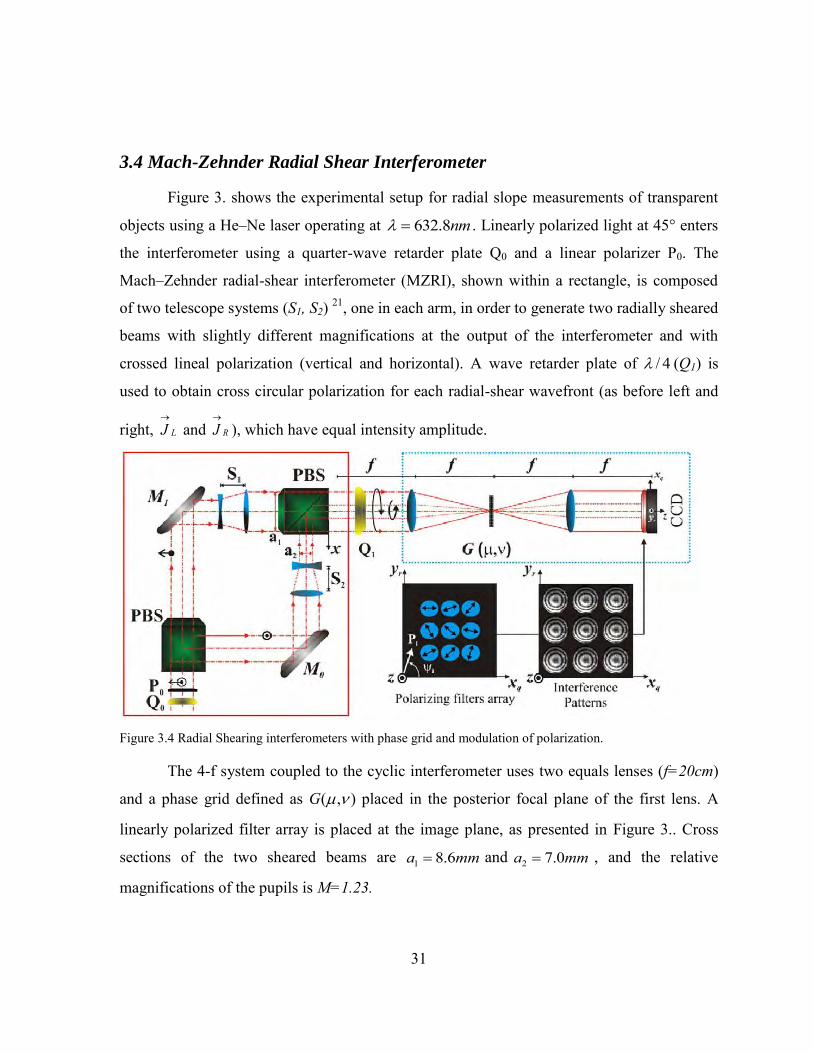
Figure 3. shows the experimental setup for radial slope measurements of transparent
objects using a He–Ne laser operating at nm8.632 . Linearly polarized light at 45° enters
the interferometer using a quarter-wave retarder plate Q0 and a linear polarizer P0. The
Mach–Zehnder radial-shear interferometer (MZRI), shown within a rectangle, is composed
of two telescope systems (S1, S2) 21, one in each arm, in order to generate two radially sheared
beams with slightly different magnifications at the output of the interferometer and with
crossed lineal polarization (vertical and horizontal). A wave retarder plate of 4/ (Q1) is
used to obtain cross circular polarization for each radial-shear wavefront (as before left and
right, LJ
and RJ
), which have equal intensity amplitude.
Figure 3.4 Radial Shearing interferometers with phase grid and modulation of polarization.
The 4-f system coupled to the cyclic interferometer uses two equals lenses (f=20cm)
and a phase grid defined as ),( G placed in the posterior focal plane of the first lens. A
linearly polarized filter array is placed at the image plane, as presented in Figure 3.. Cross
sections of the two sheared beams are mma 6.81 and mma 0.72 , and the relative
magnifications of the pupils is M=1.23.

32
Figure 3. shows experimental results for samples with radial symmetry and their
associated radial slopes. Figure 3.(a) presents a characteristic radial-shear interference pattern
obtained by interfering spherical wavefronts as a reference. The interference patterns
obtained represent contours of constant radial slope, being symmetric about the center of
curvature of the incident wavefront. Figure 3.(a) presents the radial slope with no sample and
Figure 3.(b) shows the radial slope of an ophthalmic lens with a cross section of 5 mm.
Figure 3. shows the deformation caused by gravity in a lubricating oil drop placed
over a microscope slide. The fringe pattern represents the stress field associated with the
stabilization of the oil drop on the slide.
Figure 3.5 Experimental results for samples with radial symmetry and their associated radial slopes.
Figure 3.6 Lubricating oil that was placed on a microscope slide.

33
With the purpose of showing the capability of the optical system to study dynamic
events (4D), we present results for lubricating oil that was placed on a microscope slide and
then evaporated using a tin soldiering iron. The corresponding interferograms for successive
captures of the CCD camera are shown in Figure 3., along with its associated radial slope
Figure 3.7 Lubricating oil that was placed on a microscope slide and then evaporated using a tin soldering iron.

34
3.5 Conclusion
Two systems were implemented: A cyclic shear interferometer and a Mach-Zehnder
configuration. By adding a 4-f system with two crossed phase grating in the frequency plane,
replicas of the output interferogram can be obtained. Each of these replicas can be freely
phase shifted by polarization techniques. By selecting replication order with almost same
amplitude intensity, a fringe pattern normalization algorithm can be avoided. The main issue
to take into account is that the sample needs to be a phase sample.

35
Chapter 4
Dynamic Temperature Profile Measurements
In this chapter, an optical system capable of follow temperature field variations
outside a thin-flame was implemented. The polarization phase shifting technique and a
Michelson interferometer that is coupled to a 4-f system with a Ronchi grating placed at the
frequency plane are used. This configuration permits to grab three phase-shifted
interferograms simultaneously by one CCD. The temperature field measurement is based on
measuring the refraction index difference by solving the inverse Abel transform, which
requires information obtained by the fringe order localization. The phase map is retrieved by
a three step algorithm. Experimental results of a dynamic thin flame are presented.
A quarter wave plate and a linear polarizer are positioned at the exit of an
interferometer that has its reference and object beams with orthogonal linear polarization, a
desired phase shift will be obtained and adjusted by the angle of the polarizer.23,44 This
consideration results suitable in the implementation for a single shift phase shifting
interferometer.
The optical setup presented for the optical phase calculation is composed by a
Polarization Michelson Interferometer (PMI) that is coupled to a 4-f system with an
amplitude grating placed in the Fourier plane. As a result, the interferogram obtained firstly
by the PMI is replicated in the image plane of the 4-f system.
Represented by the Jones calculation, the fields obtained by the reference and object
beams in the PMI are described by ),(12
1),( yxiei
yxO
and
iyxR 1
21),( , representing
left and right circular polarization states. The phase map ),( yx , represents the information to
retrieve in a single capture. Later it is related to the temperature outside of the flame. When

36
each field is observed through a linear polarizing filter and made them interfere, the result is
an interference pattern modulated by the angle of the transmission axis of the linear
polarizer.
By using an amplitude grating placed in the Fourier plane of the 4-f system, replicas
of this interference pattern are obtained and recorded in the CCD. The major drawback of
this system is the amplitude interferogram modulation obtained by the use of
phase/amplitude gratings21,45. This information can be avoided by the implementation of
fringe pattern normalization algorithms already encountered in the literature 46,47. As a
difference on the system presented previously in 19, in this work we only used a Ronchi
ruling taking the interference replicas obtained in the [ ] orders and use a fringe pattern
normalization algorithm to avoid the interference amplitude difference against the [ ]
orders with the [ ] order.
4.1 Temperature field measurement
The phase difference ),( yx between two waves passing through the same point of
the phase object, one in the presence of inhomogeneous medium and the other in the air, is
given as48–52
00
2( x, y ) n x, y,z n dz
, 4.1
where n(x,y,z) is the refractive index of the medium, n0 the refractive index of the air and is
the total length of the medium. In Eq. 4.1 the optical path difference provides the distortion
of the wavefront. In order to evaluate the index of refraction difference term, Eq. 4.1 must be
inverted. This task can be achieved depending of the structure of the phase object. Taking the
thin-flame as a phase object with radial symmetry, the equation of a bright fringe, N(x), of
the interferogram retrieved becomes48
2 2x
f r rdrN( x ) 2
r x
, 4.2

37
where 0nrnrf . Eq. 4.2 represents the Abel transform of f(r) and the index refraction difference is
retrieved by using Abel transform inversion techniques53,54. By inverting Eq. 4.2, we are able to
calculate the index of refraction profile dependent of the position. Taking into account the Gladstone-
Dale relation, expressed under ideal gas assumption, we are able to retrieve the temperature profile as:
RK
yxfPyxT
DGref
),(),(
, 4.3
taking air as a reference at T=15 °C with a pressure 2101325 mNP ,
3/225.1 mkgref ,
KkgJR 287 as the specific gas constant and KgmK DG /10226.0 33 as the Gladstone-Dale
constant at nm8.632 . Several studies concluded that the assumption of air is sufficient for
premixed flames as a sample but in a more strictly manner the Gladstone-Dale and Specific gas
constants need to be taken into account for specific local component distribution, not the scope of this
work55,56.
4.2 Experimental Setup
The proposed system is based on a PMI coupled to a 4-f system in order to obtain
replicas of the interference pattern at the output, Figure 4.1. Using a He-Ne laser as a source,
λ=632.8 nm, linearly polarized at 45° is divided in amplitude by the beam splitter (BS). In
the object and reference arm of the PMI a linear polarizer at 0° and 90° is placed
respectively, after the quarter-wave plate (QWP) located at 45° we are obtaining the
interference of beams with circular polarization in opposite directions. If we placed a linear
polarizer at this stage we could obtain an interference pattern with phase modulation
controlled twice the linear polarizer angle. By placing an amplitude grating with spatial
period of 100 lines/mm in the frequency plane of the 4-f system, we could obtain replicas
with the same capability of phase modulation by placing a linear polarizer angle in each of
the replicas obtained. As a result, we obtain the necessary interference fringe patterns with a
relative phase shift in order to retrieve the phase data map properly. The monochromatic
camera uses a CMOS sensor with 1280×1024 pixels and with a pixel pitch of 6.7μm. The

38
polarizing filter film that was used is the commercially available. (Edmund Optics TechSpecs
high contrast linear polarizing film). The size of each polarized film used in each
interferogram was of 25x25mm with its transmission axis oriented at 0°, 60° and 120°. The
wrapped phase data map was retrieved using the minimum least square algorithm of three
steps57 and the unwrapped phase data through the 2D Goldstein branch cut phase unwrapping
algorithm58.
Figure 4.1 Setup of the instantaneous polarized phase-shifting interferometer. The Polarizing Michelson Interferometer (PMI) is coupled to a 4-f system in order to obtain replicas of the interference pattern at the output. Each interferogram retrieved presents a relative phase shift of 120°. Mirror: M; Half Wave Plate : HWP; Lens: Li; Polarizers: Pi; Quarter Wave Plate : QWP; Beam Splitter : BS.
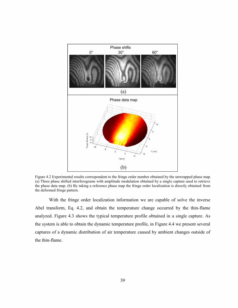
Figure 4.2 presents the three phase shifted interferograms obtained by a single
capture. After a previous calibration procedure59 we are capable of retrieve the three phase
shifted interference patterns. By implementing a fringe normalization technique we are
capable of retrieve the phase data map, Figure 4.2(b). By taking a reference phase map the
fringe order localization is directly obtained of the deformed fringe pattern, in this case
caused by a thin-flame.
39
Figure 4.2 Experimental results correspondent to the fringe order number obtained by the unwrapped phase map. (a) Three phase shifted interferograms with amplitude modulation obtained by a single capture used to retrieve the phase data map. (b) By taking a reference phase map the fringe order localization is directly obtained from the deformed fringe pattern.
With the fringe order localization information we are capable of solve the inverse
Abel transform, Eq. 4.2, and obtain the temperature change occurred by the thin-flame
analyzed. Figure 4.3 shows the typical temperature profile obtained in a single capture. As
the system is able to obtain the dynamic temperature profile, in Figure 4.4 we present several
captures of a dynamic distribution of air temperature caused by ambient changes outside of
the thin-flame.

40
Figure 4.3 Temperature profile obtained in a single capture using polarizing phase shifting techniques.
Figure 4.4 Temperature phase profiles varying in time (Representative frames).

41
4.3 Conclusion
The experimental setup for dynamic temperature field measurements using a single shot
polarization phase shifting technique has been described. This system is able to obtain three phase
shifted interferograms in only one shot. Therefore, it is suitable to carry out temporal measurements
of temperatures changes occurring outside a thin-flame. The implementations of normalization fringe
procedures present the advantage of avoiding the use of phase gratings and also the advantage of use
only three interferograms for the analysis. The system is considerably simpler than previous proposals
showing a suitable alternative to implements in an industrial ambient.

42

43
Chapter 5
Single Shot Phase Shifting Interferometry using a Two-Interferograms Phase Shifting Algorithm
A Polarization Mach Zehnder Interferometer (PMZI) was implemented to analyze
transparent samples using a two-step algorithm to retrieve optical phase data. The major
drawback of the two-step phase shifting algorithms is that it can’t be used when the phase
shift is ; this case arises when using a polarizing beam splitter as a detector when interfering
cross circular polarized beams. In order to take advantage of the PMZI, the beams have to
meet certain conditions to properly obtain the interference patterns and correctly retrieve the
optical phase data. We present the analytical model of the conditions and experimental
results for a static event. The configuration presented does not require micro-polarizer arrays
or the use of conventional polarizing filters to yield a phase shift, resulting in an increase in
the intensity and resolution of the measurements.
The most important and an industry standard nowadays are the pixelated phase mask
interferometers but one of the limitations of these systems is that the modulating phase-mask
remains fixed. By the use of phase/amplitude-gratings, more than four phase shifted
interferograms can be acquired in a single capture, but in some cases a certain fringe
normalization procedure needs to be applied to the interferograms.46 The purpose of this
research is to propose an alternative system using out of the shelf polarizing components and
also extend the use of these two current systems, gratings or pixelated phase cameras, by
following the polarizing properties of the system by the procedure presented.

44
5.1 Polarization Phase Shifting using Two-Interferograms
Figure 5.1 presents the experimental setup used based on a Polarization Mach-
Zehnder Interferometer (MZI) with the addition of two Quarter Wave Plates (QWP) in a
rotatory stage placed one in each arm of the PMZI. The main purpose of this work is to
control the relative phase shift between two interferograms by finding the proper values of
the QWP angles.
By describing the polarization states of each beam, in the interferometer, while they
go through each polarization component of the MZI, we could obtain the interferograms
equations as
),(),(),(),(),( 2,12,12,12,1 yxCyxSinyxByxAyxI , 5.1
where ),( yx is the phase map to be retrieved, A1,2(x,y) represents the bias term of the
interferogram, obtained as
211 44341),( CosCosyxA
212 44281),( CosCosyxA .
5.2
Figure 5.1 Mach-Zehnder Interferometer used to obtain two-phase shifted with a relative phase shift different from π. PBS: Polarizing Beam-Splitter, LP: Linear Polarizer, QWP:Quarter wave-plate. M: Mirror.

45
B1,2(x,y) represents the amplitude modulation term of the interferogram obtained as
2/1
444234
233
21),( 21211
CosCosCosCosyxB
212 2221),( SinSinyxB
5.3
and C1,2(x,y), the phase shift in each of the interferogram, as
12
211 22
2211),(
CosCosCosCosTanyxC
2/),(2 yxC . 5.4
By having separated each part of the interferograms, we could represent them in a 3D space.
The [x,y] axis represents the angular value ],[ 21 of each QWP1,2 and the z axis denotes the
relative change between each term (bias, amplitude and phase shift term). Figure 5.2 presents
the relative difference between the interferograms for each term.
Figure 5.2 Relative difference of the interferograms terms. a) Bias Term, b) Amplitude Modulation Term and the c) Phase Shift depending on the angles of the QWP located on each arm of the MZI.

46
With the diagram of each interferogram terms, we are able to obtain the regions
where the bias and amplitude modulation term, for both interferograms, are almost equal.
The final purpose is to obtain the permitted relative phase shift between the interferograms,
Figure 5.3. In this case we needed to obtain interferograms with a relative phase shift
different from 180º as the phase demodulation algorithm demands.
5.2 Experimental Results
Figure 5.4 presents experimental results corresponding of a misaligned to
misalignments of one of the beam expanders of the object beam. The two interferograms are
captured in a single image by the CCD camera, processed by a fringe pattern normalization
algorithm and out of this the phase demodulation term is found by a two-step demodulation
algorithm.60,61 To unwrap the phase map, the 2D Goldstein branch cut algorithm is used.58
The angles selected for this experiment are o501 and o502 , corresponding to a relative
phase shift of 160 º
Figure 5.3 Permitted QWP angles, ],[ 21 , were the amplitude and the modulation terms remain unchanged. This in order to obtain a relative phase shift different from 180° as the phase demodulation algorithm requires.

47
Figure 5.4 Experimental results obtained by misalignment of one of the collimating lens in the beam expander.
5.3 Conclusion
We presented a single shot phase shifting interferometer based on polarization
phase shifting techniques. The major novelty of the present system is to avoid the use of
special components to replicate the beam as a pixelated phase mask or amplitude/phase
gratings. The final purpose of this work is to develop a platform dedicated to describe the
phase change in real time.

48

49
Chapter 6
Dynamic birefringence mapping by a polarization image sensor
In order to expand the implementation of single shot phase shifting techniques, one
part of the Phd Project was focused on learning and developing knowledge related to
birefringence mapping. This chapter comprises some of the topics developed in a research
internship in the Center for Optical Research and Education (CORE).
In recent years, dynamic measurement of birefringence distribution has been required
to analyze internal stress structures of materials, and macromolecule flow or orientation of
functional polymer materials. Some commercial systems for a birefringence measurement
have been proposed, but there are limitations for getting higher speed phenomenon because
of the phase modulation. The birefringence distribution and azimuth angle direction can be
analyzed using single shot phase shifting techniques by using the Mueller matrix and Stokes
parameters.62,63
For two-dimensional birefringent measurements, a phase-shifting technique has been
developed before using a half-wave plate and a Babinet-Soleil compensator as phase
shifters,62 by using the replication method of the pixelated phase camera a single shot
birefringence measurement can be implemented.
The optical setup used in this study is shown in Figure 6.1. This setup consists of a
monochromatic light source, a polarizer, a quarter-wave plate, a birefringent specimen, and
the CCD camera with a microretarder array. Light passes through the polarizer whose optical
axis is horizontal, and through a quarter-wave plate whose fast axis makes an angle of 45 deg
with respect to the x axis. Then, the circularly polarized light passes through the birefringent

50
specimen. The light emerging from the birefringent specimen is acquired by the polarization-
imaging camera.
Figure 6.1 Optical setup dedicated to obtain birefringence measurements of a sample using a pixelated phase camera as a detector.
By employing the Mueller Matrix approach, the Stokes vector of the light beam
emerging from the specimen can be written as
inc
out
out
out
out
out SLPQWPMLP
SSSS
S 045,
4_
3_
2_
1_
, 6.1
where incS is the input incident light represented by
4_
3_
2_
1_
inc
inc
inc
inc
inc
SSSS
S . 6.2
where 1_incS represents the total intensity of the beam, 2_incS the intensity related for linear
horizontal/vertical polarization state, 3_incS the intensity part with linear polarization state at
incS
nput ight
i near Polarizer
u arter ave
Plate
ample nder tudy Pi el ated Phase amera ,M

51
45 and 4_incS the contribution of the light with circular polarization state. The matrix for
the linear polarizer LP at ,64,65
,
6.3
a quarter wave plate at 45 degrees,
001001001000
0001
45QWP ,
6.4
and the sample under study with phase difference and principal optical axis direction is:
.
6.5
By making the corresponding matrix multiplication, the detected intensity is obtained
by taking the first element of the output state ( 1_outS ).
22sinsin121
01_ ISI out 6.6
Suppose the light intensity is I1, I2, I3, and I4 when the direction of the analyzer is
0°, 45°, 90°, and 135°, respectively. Applying the phase-shifting method, the incident light
intensity I0,
24321
0IIII
I
, 6.7
the principal a is direction φ,
)()(
tan21
42
131
IIII
6.8
and the phase difference Δ can be e pressed as 63
000002sin2cos2sin2sin02cos2sin2cos2cos02sin2cos1
21
2
2
LP
cos2cossin2sinsin02cossin2cos)cos1(12cos2sin)cos1(02sinsin2cos2sin)cos1(2sin)cos1(10
0001
2
2
,
M
52
0
242
2131 )()(
sinI
IIII .
6.9
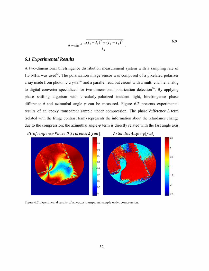
6.1 Experimental Results
A two-dimensional birefringence distribution measurement system with a sampling rate of
1.3 MHz was used66. The polarization image sensor was composed of a pixelated polarizer
array made from photonic crystal67 and a parallel read out circuit with a multi-channel analog
to digital converter specialized for two-dimensional polarization detection66. By applying
phase shifting algorism with circularly-polarized incident light, birefringence phase
difference and azimuthal angle can be measured. Figure 6.2 presents experimental
results of an epoxy transparent sample under compression. The phase difference term
(related with the fringe contrast term) represents the information about the retardance change
due to the compression; the azimuthal angle term is directly related with the fast angle axis.
Figure 6.2 Experimental results of an epoxy transparent sample under compression.

53
By setting the polarization imaging camera at 1000 fps we were able to retrieve an
image of 1024x1024 pixels, the compression of the epoxy sample changing in time was
followed. Representative frames are presented in Figure 6.3. Another experimental result is
the follow of the compression occurred in an acrylic block hitted by a hammer, in this case
the polarization camera was set at 10,000 fps, Figure 6.4 presents representatives figures of
the event.
Figure 6.3 Temporal evolution of the epoxy transparent sample under compression by observing the birefringence distribution varying in time.
Figure 6.4 Temporal evolution of an acrylic block hit by a hammer at 10,000 fps.

54
6.2 Conclusion
A birefringence imaging system composed by a high speed pixelated camera was
presented. The system tested is capable of following dynamic phase changes at speeds of up
to 10,000 fps. Although the measurement system is based on purely polarization properties of
the sample, this research field can be associated with the work done in interferometry
measurements by taking into account that the information is carried on the amplitude
modulation change of the interferogram.

55
Conclusions and Future Work
This thesis explored the concept of polarization phase shifting techniques, focusing
particularly on implementation of single shot phase interferometers based on a 4-f system.
Polarization phase shifting techniques requires several conditions that need to be met in order
to be implemented, the most important is that the reference and object beams have
orthogonal polarization states. By using the 4-f system with gratings placed on the frequency
plane, an amplitude modulation is produced on the image plane in each of the replica
obtained. This can be dealt by using normalization procedures or by using replicas orders
with almost the same amplitudes.
Several single shot phase shifting interferometry techniques were successfully
implemented to analyze phase changes varying in time. The approach developed in this thesis
has served to propose new interferometric systems, as the common path configuration based
on grating interferometry techniques. Different types of measurements have been done, such
as slope phase measurements and temperature profiles. The proposed systems consider the
geometric and polarization properties of the interferometer. Table 1 presents advantages and
disadvantages of the systems implemented.
The common path interferometer, based in grating interferometry techniques, takes
into account the intrinsic π-phase shifted replicated interferograms obtained to reduce the
number of linear polarizer placed at the output, the system have the limitations of the size of
the lens and the quarter wave plates used.
The slope phase measurement system presented have the property of obtain more
interferograms to process the phase, opening possibilities to use different phase processing
algorithms. One of the disadvantages of this system is that by increasing the number of
replicas a reduction of the spatial resolution is encountered.
A system capable of measuring temperature profiles was implemented. The system
uses only three interferograms for the analysis. A disadvantage presented is the fringe

56
normalization process to compensate the amplitude change due to the replication method
used. This system is simpler than the previous proposed showing a suitable option for
industrial environments applications.
A system were proposed with the principal characteristic of process the phase by
using a two-interferogram algorithm and avoiding the usage of the 4-f system as the
replication method. The phase shift was controlled by polarization properties of the reference
and object beams.
A 2D birefringence mapping system was implemented. The system is based in treat
the sample as a linear retarder. By taking into account properties related with the phase
shifting algorithms, the information is encoded in the phase and its amplitude modulation.
One of the main limitations common in the implemented systems is that the samples
need to maintain the polarization properties of the beam, and that they have to be phase
sample. As a future work, considerations based on the Mueller matrix approach of the sample
can be used as a compensation of this. Another future work is to use the pixelated camera as
a calibration system of a polarization interferometer.

57
Single Shot Phase Shifting Interferometry Based in Polarization Techniques
System Advantages Disadvantages Quasi-Common Path Interferometer
Insensibility of external vibration due to of the common path characteristic.
Reduction of the numbers of the linear polarizer mask due to of the -shift intrinsically obtained.
Reduction of the spatial resolution. Field of view highly dependent of the
light source, lens and period of the grating used.
Slope Phase Measurements
Obtain more than 4 interferograms.
Sample placed outside of the interferometer.
Slope of the phase change obtained directly.
Reduction of the spatial resolution. Phase information obtained through
an integration process.
Temperature Profile Measurements
Three interferograms to process the phase.
Temperature is obtained by projected lines.
Polarization state of the object beam may be affected by the sample.
Contrast changes compensated by a fringe pattern normalization algorithm.
Two-Interferograms Phase Shifting Interferometer
Avoid the usage of the 4-f system.
Two interferograms to process the phase.
Phase algorithm demands a phase shift different from .
Contrast changes compensated by a fringe pattern normalization algorithm.
2D Birefringence Mapping
High speed measurement capability.
Sample is treated as a pure linear retarder.
Birefringence measurement range of . It goes from 0 to
Table 1 – Advantages and disadvantages of the implemented systems.

58

59
References
1. Yamaguchi, ., Kato, J., Ohta, . & Mizuno, J. “Image formation in phase-shifting digital holography and applications to microscopy.” Applied Optics 40, 6177–6186 (2001).
2. Gorthi, . . & Rastogi, P. “Fringe projection techniques: hither we are?” Optics and Lasers in Engineering 48, 133–140 (2010).
3. Martínez, A., Rayas, J. A., Puga, H. J. & Genovese, K. “ terative estimation of the topography measurement by fringe-projection method with divergent illumination by considering the pitch variation along the and z directions.” Optics and Lasers in Engineering 48, 877–881 (2010).
4. Liu, J.-P. & Poon, T.- . “Two-step-only quadrature phase-shifting digital holography.” Optics Letters 34, 250–252 (2009).
5. Nakadate, . “Vibration measurement using phase-shifting speckle-pattern interferometry.” Applied Optics 25, 4162 (1986).
6. Griffin, D. . “Phase-shifting shearing interferometer.” Optics Letters 26, 140–141 (2001).
7. Kothiyal, M. P. & Delisle, . “ hearing interferometer for phase shifting interferometry with polarization phase shifter.” Applied Optics 24, 4439 (1985).
8. Serrano-García, D. I., Toto-Arellano, N. I., Martínez-Garcia, A., Rayas-Álvarez, J. A., Téllez-Quiñones, A. & Rodríguez-Zurita, G. “ imultaneous phase-shifting cyclic interferometer for generation of lateral and radial shear.” Revista Mexicana de Física 57, 255–258 (2011).
9. Novak M., Millerd J., Brock N., North-Morris M., Hayes J., . J. “Analysis of a micropolarizer array-based simultaneous phase-shifting interferometer.” Applied Optics 44, 6861–6868 (2005).
10. Neal, R. M. & Wyant, J. . “Polarization phase-shifting point-diffraction interferometer.” Applied Optics 45, 3463–3476 (2006).
60
11. Rodriguez-Zurita, G., Toto-Arellano, N.-I., Meneses-Fabian, C. & Vázquez-Castillo, J. F. “One-shot phase-shifting interferometry: five, seven, and nine interferograms.” Optics Letters 33, 2788–2790 (2008).
12. Baker, K. . & tappaerts, E. A. “A single-shot pixellated phase-shifting interferometer utilizing a liquid-crystal spatial light modulator.” Optics Letters 31, 733–735 (2006).
13. Wyant, J. . “Vibration insensitive interferometric optical testing - OSA Technical Digest ( D) .” in Frontiers in Optics 2004/Laser Science XXII/Diffractive Optics and Micro-Optics/Optical Fabrication and Testing OTuB2 (Optical Society of America, 2004). at <http://www.opticsinfobase.org/abstract.cfm?URI=OFT-2004-OTuB2>
14. Chen, L.-C., Yeh, S.-L., Tapilouw, A. M. & Chang, J.- . “3-D surface profilometry using simultaneous phase-shifting interferometry.” Optics Communications 283, 3376–3382 (2010).
15. Millerd, J., Brock, N., Hayes, J., North-Morris, M., Kimbrough, B. & Wyant, J. C. in Fringe 2005 640–647 (2006). doi:10.1007/3-540-29303-5_86
16. ervin, M. & Estrada, J. . “Error-free demodulation of pixelated carrier frequency interferograms.” Optics Express 18, 18492–18497 (2010).
17. Padilla, J. M., ervin, M. & Estrada, J. . “ ynchronous phase-demodulation and harmonic rejection of 9-step pi elated dynamic interferograms.” Optics Express 20, 11734 (2012).
18. Brock, N., Millerd, J., yant, J. & Hayes, J. “Pi elated phase-mask interferometer.” (2005). at <http://www.google.com.tr/patents/US20050046865>
19. Toto-Arellano, N.-I., Martínez-García, A., Rodríguez-Zurita, G., Rayas-Álvarez, J. A. & Montes-Perez, A. “ lope measurement of a phase object using a polarizing phase-shifting high-frequency Ronchi grating interferometer.” Applied optics 49, 6402–6408 (2010).
20. Toto-Arellano, N.-I., Rodriguez-Zurita, G., Meneses-Fabian, C. & Vazquez-Castillo, J. F. “Phase shifts in the Fourier spectra of phase gratings and phase grids: an application for one-shot phase-shifting interferometry.” Optics Express 16, 19330–19341 (2008).
21. Serrano-García, D. I., Toto-Arellano, N.-I., Martínez-García, A. & Zurita, G. R. “Radial slope measurement of dynamic transparent samples.” Journal of Optics 14, 045706 (2012).

61
22. yant, J. . “ ourse Notes - Optics 513 - hapter 5.” at <http://fp.optics.arizona.edu/jcwyant/Optics513/ChapterNotes/Chapter05/Notes/Geometric_Phase_Shifter.pdf>
23. Bryngdahl, O. “Polarization-Type Interference-Fringe hifter.” Journal of the Optical Society of America 62, 462 (1972).
24. Hariharan, P. “Achromatic phase-shifting for white-light interferometry.” Applied Optics 35, 6823–6824 (1996).
25. Helen, . ., Kothiyal, M. P. & irohi, R. . “Achromatic phase shifting by a rotating polarizer.” Optics Communications 154, 249–254 (1998).
26. hagam, R. N. & yant, J. . “Optical frequency shifter for heterodyne interferometers using multiple rotating polarization retarders.” Applied Optics 17, 3034–5 (1978).
27. “Edmund Optics - Precision Ronchi Ruling Glass lides.” at <http://www.edmundoptics.com/testing-targets/test-targets/resolution-test-targets/precision-ronchi-ruling-glass-slides/1831?ref=related-products>
28. “Edmund Optics - Transmission Grating Beamsplitters.” at <http://www.edmundoptics.com/optics/gratings/transmission-grating-beamsplitters/1939>
29. Toto-Arellano, N.-I., Rodríguez-Zurita, G., Martínez García, A., Vázquez-Castillo, J. F. & Rayas Álvarez, J. A. “Analysis of the Pi phase-shifts obtained in the Fourier spectra of phase gratings and grids by using two-window grating interferometry.” Revista mexicana de Física 56, 281–286 (2010).
30. Goodman, J. . “ ntroduction to Fourier Optics McGraw-Hill Series in Electrical and omputer Engineering.” Quantum and Semiclassical Optics Journal of the European Optical Society Part B 8, 491 (1996).
31. Serrano-García, D. I., Toto-Arellano, N.-I., Martínez-García, A. & Zurita, G. R. “Radial slope measurement of dynamic transparent samples.” Journal of Optics 14, 45706 (2012).
32. Serrano-García, D. I., Martínez-García, A., Rayas-Alvarez, J. A., Toto-Arellano, N. I., Rodriguez-Zurita, G. & Montes-Pérez, A. “Adjustable-window grating interferometer based on a Mach-Zehnder configuration for phase profile measurements of transparent samples.” Optical Engineering 51, 055601 (2012).

62
33. Rodriguez-Zurita, G., Meneses-Fabian, C., Toto-Arellano, N.-I., Vázquez-Castillo, J. F. & Robledo- ánchez, . “One-shot phase-shifting phase-grating interferometry with modulation of polarization: case of four interferograms.” Optics Express 16, 7806–7817 (2008).
34. Malacara, D., Servín, M. & Malacara, Z. "Interferogram Analysis For Optical Testing,". Interferogram Analysis For Optical Testing, Second Edition 440 (2005). doi:doi:10.1201/9781420027273.fmatt
35. Rodriguez-Zurita, G., Meneses-Fabian, C., Toto-Arellano, N.-I., Vázquez-Castillo, J. F. & Robledo- ánchez, . “One-shot phase-shifting phase-grating interferometry with modulation of polarization: case of four interferograms.” Optics Express 16, 7806 (2008).
36. Kemao, ., Xiaoping, . & Asundi, A. “Grating-Based Real-Time Polarization Phase- hifting nterferometry: Error Analysis.” Applied Optics 41, 2448 (2002).
37. Toto-Arellano, N. I., Rodriguez-Zurita, G., Meneses-Fabian, C. & Vázquez-Castillo, J. F. “A single-shot phase-shifting radial-shearing interferometer.” Journal of Optics A: Pure and Applied Optics 11, 45704 (2009).
38. Rodríguez-Zurita, G., Toto-Arellano, N. I., Meneses-Fabian, C. & Vázquez-Castillo, J. F. “Adjustable lateral-shear single-shot phase-shifting interferometry for moving phase distributions.” Measurement Science and Technology 20, 115902 (2009).
39. Strojnik, M., Paez, G. & Mantravadi, M. in Optical Shop Testing 122–184 (John Wiley & Sons, Inc., 2006). doi:10.1002/9780470135976.ch4
40. Murty, M. V & hukla, R. P. “Radial shearing interferometers using a laser source.” Applied Optics 12, 2765–7 (1973).
41. Matsuda, K., Minami, Y. & Eiju, T. “Novel holographic shearing interferometer for measuring lens lateral aberration.” Applied Optics 31, 6603–9 (1992).
42. Ghai, D. P., Vyas, ., enthilkumaran, P. & irohi, R. . “Detection of phase singularity using a lateral shear interferometer.” Optics and Lasers in Engineering 46, 419–423 (2008).
43. Patorski, K. “ hearing interferometry and the moire method for shear strain determination.” Applied Optics 27, 3567–72 (1988).
44. Okoomian, H. J. “A two-beam polarization technique to measure optical phase.” Applied Optics 8, 2363_1–2365 (1969).

63
45. Millerd, J. E., Brock, N. J., Hayes, J. B., North-Morris, M. B., Novak, M. & Wyant, J. . “Pi elated phase-mask dynamic interferometer.” Proc. SPIE 5531, 304–314 (2004).
46. uiro ga, J. A., Antonio G me z-Pedrero, J. & Garc a-Botella, Á. “Algorithm for fringe pattern normalization.” Optics Communications 197, 43–51 (2001).
47. Antonio uiro ga, J. & ervin, M. “ sotropic n-dimensional fringe pattern normalization.” Optics Communications 224, 221–227 (2003).
48. Vest, C. M. "Holographic Interferometry". (Wiley Series in Pure & Applied Optics, 1979).
49. Correia, D. P., Ferrao, P. & Caldeira-Pires, A. “Advanced 3D Emission Tomography Flame Temperature ensor.” Combustion Science and Technology 163, 1–24 (2001).
50. Madanipour, K., Fatehi, . & Parvin, P. “Measurement of temperature, refractive index, density distribution, and convective heat transfer coefficient around a vertical wire by the Michelson interferometer.” Proc. SPIE 7389, 73892X–73892X–8 (2009).
51. Aggarwal, A. ., Kaura, . K., hhachhia, D. . & harma, A. . “Holographic optics-based interferometer for real-time testing of phase objects.” Optics & Laser Technology 36, 545–549 (2004).
52. hakher, . & Nirala, A. K. “A review on refractive index and temperature profile measurements using laser-based interferometric techniques.” Optics and Lasers in Engineering 31, 455–491 (1999).
53. Kalal, M. & Nugent, K. A. “Abel inversion using fast Fourier transforms.” Applied optics 27, 1956–1959 (1988).
54. Ampem-Lassen, E., Huntington, S. T., Dragomir, N. M., Nugent, K. A. & Roberts, A. “Refractive inde profiling of a ially symmetric optical fibers: a new technique.” Optics Express 13, 3277–3282 (2005).
55. Zhu, J., Huang, S., Lv, . & Zhou, H. “ tudy on the measurement of temperature field using laser holographic interferometry.” Frontiers in Energy 5, 120–124 (2011).
56. i, J. A., eung, . ., ong, . O. & Probert, . D. “Temperature-field measurements of a premixed butane/air circular impinging-flame using reference-beam interferometry.” Applied Energy 83, 1307–1316 (2006).
57. ervin, M., Estrada, J. . & uiroga, J. A. “The general theory of phase shifting algorithms.” Optics Express 17, 21867–21881 (2009).
64
58. Dennis C. Ghiglia, M. D. P. "Two-Dimensional Phase Unwrapping: Theory, Algorithms, and Software". 512 (Wiley, 1998).
59. Toto-Arellano, N. I., Serrano-García, D. I., Martínez-García, A., Rodríguez-Zurita, G. & Montes-Pérez, A. “4D profile of phase objects through the use of a simultaneous phase shifting quasi-common path interferometer.” Journal of Optics 115502, (2011).
60. Vargas, J., uiro ga, J. A., Belenguer, T., ervín, M. & Estrada, J. . “Two-step self-tuning phase-shifting interferometry.” Optics Express 19, 638–648 (2011).
61. Vargas, J., uiro ga, J. A., orzano, . O. ., Estrada, J. . & arazo, J. M. “Two-step demodulation based on the Gram– chmidt orthonormalization method.” Optics Letters 37, 443 (2012).
62. Otani, Y. in Handbook of Optical Metrology, Principles and Applications (Yoshizawa, T.) 615–630 (CRC, 2009).
63. Otani, Y., himada, T., Yoshizawa, T. & me da, N. “Two-dimensional birefringence measurement using the phase shifting technique.” Optical Engineering 33, 1604 (1994).
64. in Polarized Light, Revised and Expanded (CRC Press, 2003). doi:doi:10.1201/9780203911587.axc
65. Bass, M., tryland, E. . V & illiams, D. R. “Handbook of Optics Volume Classical Optics, Vision Optics, X-Ray Optics 2nd edition.” (2001).
66. Onuma, T. & Otani, Y. “A development of two-dimensional birefringence distribution measurement system with a sampling rate of 1.3MHz.” Optics Communications 315, 69–73 (2014).
67. “Photonic attice.” at <http://www.photonic-lattice.com/>

65
Published Articles
Journal Articles
1. N. I. Toto-Arellano, D. I. Serrano-García, A. Martínez-García, "Parallel two-step phase
shifting interferometry using a double cyclic shear interferometer", Optics Express, Vol.
21(26), pp 31983-31989, (2013).
2. D. I. Serrano-García, A. Martínez-García, N. I. Toto-Arellano and Yukitoshi Otani,
"Dynamic temperature field measurements using a polarization phase shifting technique",
Optical Engineering, Vol. 53(11), (2014).
3. D. I. Serrano-García, N. I. Toto-Arellano, A. Martínez-García and G. Rodríguez-Zuríta,
"Radial slope measurement of dynamic transparent samples", Journal of Optics, Vol. 14,
pp 045706-045714, (2012).
4. D. I. Serrano-García, N. I. Toto-Arellano, A. Martínez-García, J. A. Rayas-Álvarez, G.
Rodríguez-Zuríta and A. Montes-Pérez, "Adjustable-window grating interferometer
based on a Mach-Zehnder configuration for phase profile measurements of transparent
samples",Optical Engineering, Vol. 51, pp 055601-055608, (2012).
5. D. I. Serrano-García, N. I. Toto-Arellano, A. Martínez-García, J. A. Rayas Álvarez and
G. Rodríguez-Zuríta, "Dynamic phase profile of phase objects based in the use of a quasi-
common path interferometer", Optik, Vol. 1, pp 1742-1745, (2012).
6. N. I. Toto-Arellano, D. I. Serrano-García, A. Martínez-García, G. Rodríguez-Zuríta and
A. Montes-Pérez, “4D profile of phase objects through the use of a simultaneous phase
shifting quasi-common path interferometer”, Journal of Optics, Vol. 13, pp 115502-
115510, (2011).
7. D. I. Serrano-García, N. I. Toto-Arellano, A. Martínez-García, J. A. Rayas Álvarez, A.
Téllez-Quiñones, G. Rodríguez-Zurita, “ imultaneous phase-shifting cyclic
interferometer for generation of lateral and radial shear”, Revista Mexicana de Física,
Vol. 57(3), pp 0255-0258, (2011).

66
Book Chapters
1. N. I. Toto-Arellano, D. I. Serrano-García, A. Martínez-García and G. Rodríguez-Zuríta,
“Simultaneous Phase Shifting Shearing Interferometry for Measurement of Static and
Dynamic Phase Objects”, Book: Interferometry - Research and Applications in Science
and Technology, Edited by Dr Ivan Padron, ISBN: 978-953-51-0403-2, InTech, DOI:
10.5772/34187, (2012).
2. N. I. Toto-Arellano, G. Rodríguez-Zuríta, A. Martínez-García, D. I. Serrano-García and
M. G. Hernández-Orduña, “E perimental π Phase-Shifts Observed in the Fourier Spectra
of Phase Gratings and Applications in Simultaneous PSI”, Book: Interferometry -
Research and Applications in Science and Technology, edited by Dr Ivan Padron, ISBN:
978-953-51-0403-2, InTech, DOI: 10.5772/36859, (2012).
Technical Handbook
1. N. I. Toto-Arellano, G. Rodríguez Zurita and D. I. Serrano-García, “Teoría Física de
Rejillas de Amplitud y Fase”, Editorial Académica Española, ISBN-10: 384657030,
(2011).
Conference Proceedings
1. D. I. Serrano-García, A. Martínez-García, J. A. Rayas-Álvarez, G. Rodríguez-Zuríta and
A. Montes-Pérez, "Parallel phase shifting interferometry using a double cyclic shear
interferometer", N. I. Toto-Arellano, 22nd Congress of the International Commission for
Optics: Light for the Development of the World, Proceedings of the SPIE, Volume 8011,
article id. 80110N, 6 pp. (2011).
2. D. I. Serrano-García, N. I. Toto-Arellano, A. Martínez-García, J. A. Rayas-Álvarez and
G. Rodríguez-Zuríta, "Simultaneous phase shifting interferometry based in a Mach
Zehnder interferometer for measurement of transparent samples", 22nd Congress of the
International Commission for Optics: Light for the Development of the World,
Proceedings of the SPIE, Volume 8011, article id. 80110M, 6 pp. (2011).

67
3. N. I. Toto-Arellano, A. Martínez-García, J. A. Rayas-Álvarez, D. I. Serrano-García,
"Slope measurement of a phase object", 22nd Congress of the International Commission
for Optics: Light for the Development of the World, Proceedings of the SPIE, Volume
8011, article id. 80110P, 6 pp. (2011).
4. D. I. Serrano-García, N. I. Toto-Arellano, A. Martínez-García and G. Rodríguez-Zuríta,
"Radial slope measurements of transparent samples using phase shifting interferometry
by polarization”, Eighth Symposium Optics in Industry, Proceedings of SPIE Volume
8287, article id. 828714, 6 pp. (2011).
5. D. I. Serrano-García, N. I. Toto-Arellano, A. Martínez-García, G. Rodríguez-Zuríta and
A. Montes-Pérez, "Single shot phase shifting interferometry for measurement of
transparent samples", Dimensional Optical Metrology and Inspection for Practical
Applications, Proceedings of SPIE Volume 8133, article id. 8133 0X, 6 pp. (2011).
Awards Received
1. Best Student Presentation Award granted by OSA during 2013 CIOMP-OSA Summer Session: Optical Engineering, Design and Manufacturing. Changchun, China, August 2013.
2. Scholarship granted by SPIE, the International Society for Optics and Photonics for his
potential contributions to the field of optics, photonics or related field. San Diego,
Californía, USA, August 2011.
3. Full Travel Grant granted by the APS to assist the 5th Canadian-American-Mexican
Graduate Student Physics Conference. Washington D.C, USA, September 2011.
4. OSA Foundation travel grant to assist The Frontiers in Optics 2011 Conference.San Jose,
California, USA, October 2011.
5. 1st Place SPIE Student Poster Presentation during the 22nd International Commission for
Optics (ICO-22). Puebla, Puebla, México. August 2011.