single-reduction differential carriers · single-reduction differential carriers single rear drive...
TRANSCRIPT

Single-ReductionDifferential Carriers
Single Rear Drive Axles, Rear-Rear TandemDrive Axles and Front Drive Steer Axles
Maintenance Manual 5A
RS and RT SeriesSingle-ReductionAxles (Single, Rear of Tandem)
MX and RF Series Front Drive Axles
Revised 02-03
Service Notes
Service Notes
Before You Begin
This manual provides instructions for the Meritor MX-, RS-, RT- and RF-Series axles. Before you begin procedures:
1. Read and understand all instructions and procedures before you begin to service components.
2. Read and observe all Caution and Warning safety alerts that precede instructions or procedures you will perform. These alerts help to avoid damage to components, serious personal injury, or both.
3. Follow your company’s maintenance and service, installation, and diagnostics guidelines.
4. Use special tools when required to help avoid serious personal injury and damage to components.
Safety Alerts, Torque Symbol and Notes
Access Product and Service Information on Our Website
Visit the DriveTrain Plus
TM
by ArvinMeritor Tech Library at arvinmeritor.com to access and order product and service information.
To Order Information by Phone
Call ArvinMeritor’s Customer Service Center at 800-535-5560 to order the following publications.
O
Lubrication (Maintenance Manual 1)
O
Single-Reduction Differential Carriers (Maintenance Manual 5)
O
Single-Reduction Forward Differential Carriers on Tandem and Tridem Axles (Maintenance Manual 5L)
O
Drive Axle Housings (Maintenance Manual 8)
O
Approved Rear Drive Axle Lubricants (TP-9539)
O
Driver Instruction Kit (TP-9579)
O
Failure Analysis for Drive Axle Components (TP-9955)
O
Traction Controls package that contains two videos: Splitting the Difference (T-87127V) and Driver-Controlled, Full-Locking Main Differential (T-9007V). Order T-95125V for this package. Each video is also available separately.
O
Drivetrain Plus
TM
by ArvinMeritor Technical Electronic Library on CD. Features product and service information on most Meritor, ZF Meritor and Meritor WABCO products. $20. Order TP-9853.
How to Order Tools and Supplies Specified in This Manual
Call ArvinMeritor’s Commercial Vehicle Aftermarket at 888-725-9355 to order Meritor tools and supplies.
SPX Kent-Moore, 28635 Mound Road, Warren, Michigan, 48092. Call the company’s customer service center at 800-345-2233, or visit their website at spxkentmoore.com.
WARNING
A Warning alerts you to an instruction or procedure that you must follow exactly to avoid serious personal injury.
CAUTION
A Caution alerts you to an instruction or procedure that you must follow exactly to avoid damage to components.
A torque symbol alerts you to tighten fasteners to a specified torque value.
NOTE
A Note provides information or suggestions that help you correctly service a component.

Table of Contents
Exploded Views
. . . . . . . . . . . . . . . . . . . . . . . . . . . . . . . . . . . . . . . . . . . . . . . . . . . . . . . . . . . . . . . . . . . . . . . .1
Section 1: Introduction
Standard Single-Reduction Carriers Without Differential Lock . . . . . . . . . . . . . . . . . . . . . . . . . . . . . . . . .2Single-Reduction Carriers with DCDL (Driver-Controlled Main Differential Lock) . . . . . . . . . . . . . . . . . .3Axle Models Covered in this Manual . . . . . . . . . . . . . . . . . . . . . . . . . . . . . . . . . . . . . . . . . . . . . . . . . . . . . .4Stall Testing with Automatic Transmissions
Section 2: Removal and Disassembly
Removal . . . . . . . . . . . . . . . . . . . . . . . . . . . . . . . . . . . . . . . . . . . . . . . . . . . . . . . . . . . . . . . . . . . . . . . . . . . . .5Differential Carrier from the Axle Housing Carrier from the Axle . . . . . . . . . . . . . . . . . . . . . . . . . . . . . . . . . . . . . . . . . . . . . . . . . . . . . . . . . . . . . . . . . . .7Differential and Ring Gear from the Carrier . . . . . . . . . . . . . . . . . . . . . . . . . . . . . . . . . . . . . . . . . . . . . . . .9Disassembly . . . . . . . . . . . . . . . . . . . . . . . . . . . . . . . . . . . . . . . . . . . . . . . . . . . . . . . . . . . . . . . . . . . . . . . . .10Differential and Ring Gear Assembly Removal . . . . . . . . . . . . . . . . . . . . . . . . . . . . . . . . . . . . . . . . . . . . . . . . . . . . . . . . . . . . . . . . . . . . . . . . . . . .12Drive Pinion and Bearing Cage from the Carrier Disassembly . . . . . . . . . . . . . . . . . . . . . . . . . . . . . . . . . . . . . . . . . . . . . . . . . . . . . . . . . . . . . . . . . . . . . . . . .14Drive Pinion and Bearing Cage
Section 3: Prepare Parts for Assembly
Clean and Inspect Yokes . . . . . . . . . . . . . . . . . . . . . . . . . . . . . . . . . . . . . . . . . . . . . . . . . . . . . . . . . . . . . . .17Clean Ground and Polished Parts Clean Rough Parts . . . . . . . . . . . . . . . . . . . . . . . . . . . . . . . . . . . . . . . . . . . . . . . . . . . . . . . . . . . . . . . . . . . .18Clean Axle Assemblies Dry Parts After Cleaning Prevent Corrosion on Cleaned Parts Inspect Parts Repair or Replace Parts . . . . . . . . . . . . . . . . . . . . . . . . . . . . . . . . . . . . . . . . . . . . . . . . . . . . . . . . . . . . . . . .20Repair Welding on Axle Housings . . . . . . . . . . . . . . . . . . . . . . . . . . . . . . . . . . . . . . . . . . . . . . . . . . . . . . .21For Complete Welding Instructions on Meritor Drive Axle Housings Prepare the Axle Do Not Bend or Straighten a Damaged Drive Axle Housing . . . . . . . . . . . . . . . . . . . . . . . . . . . . . . . . . .22Fasteners Removing Fasteners Secured with Adhesive New Fasteners with Pre-Applied Adhesive . . . . . . . . . . . . . . . . . . . . . . . . . . . . . . . . . . . . . . . . . . . . . . . .23Original or Used Fasteners Applying Adhesive and Silicone Gasket MaterialMeritor Specification 2297-T-4180 Adhesive in Differential Bearing BoresThree Bond 1216, or Equivalent, Silicone Gasket Material . . . . . . . . . . . . . . . . . . . . . . . . . . . . . . . . . . .24Carrier-to-Housing Joint Repair Installing Tight Fit Yokes and POSE™ Seal . . . . . . . . . . . . . . . . . . . . . . . . . . . . . . . . . . . . . . . . . . . . . . . .26Installing Any Type Yoke with a Unitized Pinion Seal (UPS) Clean, Inspect and Install the Yoke After Installing a Unitized Pinion Seal . . . . . . . . . . . . . . . . . . . . . .28General Yoke and U-Joint Reassembly . . . . . . . . . . . . . . . . . . . . . . . . . . . . . . . . . . . . . . . . . . . . . . . . . . .29Gear Sets Examples

Table of Contents
Section 4: Assembly
Assembly . . . . . . . . . . . . . . . . . . . . . . . . . . . . . . . . . . . . . . . . . . . . . . . . . . . . . . . . . . . . . . . . . . . . . . . . . . . 30Drive Pinion, Bearings and Bearing Cage Installation One-Piece Spigot Bearing on the Drive Pinion with Snap Ring One-Piece Spigot Bearing on the Drive Pinion Without Snap Ring . . . . . . . . . . . . . . . . . . . . . . . . . . . . 31Two-Piece Spigot Bearing on the Drive Pinion . . . . . . . . . . . . . . . . . . . . . . . . . . . . . . . . . . . . . . . . . . . . 32Drive Pinion . . . . . . . . . . . . . . . . . . . . . . . . . . . . . . . . . . . . . . . . . . . . . . . . . . . . . . . . . . . . . . . . . . . . . . . . . 34Adjustment Pinion Bearing Preload Shim Pack Thickness for a New Drive Pinion . . . . . . . . . . . . . . . . . . . . . . . . . . . . . . . . . . . . . . . . . . . . . 38Installation . . . . . . . . . . . . . . . . . . . . . . . . . . . . . . . . . . . . . . . . . . . . . . . . . . . . . . . . . . . . . . . . . . . . . . . . . . 39Drive Pinion, Bearing Cage and Shim Pack into the Carrier Tight Fit Yokes and POSE™ Seal . . . . . . . . . . . . . . . . . . . . . . . . . . . . . . . . . . . . . . . . . . . . . . . . . . . . . . . . 40Any Type Yoke with a Unitized Pinion Seal (UPS) . . . . . . . . . . . . . . . . . . . . . . . . . . . . . . . . . . . . . . . . . . 41Clean, Inspect and Install the Yoke After Installing a Unitized Pinion Seal . . . . . . . . . . . . . . . . . . . . . . 43Assembly . . . . . . . . . . . . . . . . . . . . . . . . . . . . . . . . . . . . . . . . . . . . . . . . . . . . . . . . . . . . . . . . . . . . . . . . . . . 44Main Differential and Ring Gear Assembly Installation . . . . . . . . . . . . . . . . . . . . . . . . . . . . . . . . . . . . . . . . . . . . . . . . . . . . . . . . . . . . . . . . . . . . . . . . . . 47Differential and Ring Gear Assembly Adjust Differential Bearing Preload . . . . . . . . . . . . . . . . . . . . . . . . . . . . . . . . . . . . . . . . . . . . . . . . . . . . . . 48Method 1 Method 2 . . . . . . . . . . . . . . . . . . . . . . . . . . . . . . . . . . . . . . . . . . . . . . . . . . . . . . . . . . . . . . . . . . . . . . . . . . . 49Check Ring Gear Runout . . . . . . . . . . . . . . . . . . . . . . . . . . . . . . . . . . . . . . . . . . . . . . . . . . . . . . . . . . . . . . 50Ring Gear Backlash Adjustment . . . . . . . . . . . . . . . . . . . . . . . . . . . . . . . . . . . . . . . . . . . . . . . . . . . . . . . . 51Check Gear Set Tooth Contact Patterns (Backlash) . . . . . . . . . . . . . . . . . . . . . . . . . . . . . . . . . . . . . . . . . 52Installation . . . . . . . . . . . . . . . . . . . . . . . . . . . . . . . . . . . . . . . . . . . . . . . . . . . . . . . . . . . . . . . . . . . . . . . . . . 56Adjust the Thrust Screw Differential Carrier into Axle Housing . . . . . . . . . . . . . . . . . . . . . . . . . . . . . . . . . . . . . . . . . . . . . . . . . . . . 57
Section 5: Driver-Controlled Main Differential Lock
Driver-Controlled Main Differential Lock Assembly . . . . . . . . . . . . . . . . . . . . . . . . . . . . . . . . . . . . . . . . 59Removal . . . . . . . . . . . . . . . . . . . . . . . . . . . . . . . . . . . . . . . . . . . . . . . . . . . . . . . . . . . . . . . . . . . . . . . . . . . . 60Differential Carrier from Axle Housing Axle Setup for DCDL Disassembly DCDL Assembly Manual Engaging Methods . . . . . . . . . . . . . . . . . . . . . . . . . . . . . . . . . . . . . . . . . . . . . . 61Differential and Gear Assembly . . . . . . . . . . . . . . . . . . . . . . . . . . . . . . . . . . . . . . . . . . . . . . . . . . . . . . . . 62Installation . . . . . . . . . . . . . . . . . . . . . . . . . . . . . . . . . . . . . . . . . . . . . . . . . . . . . . . . . . . . . . . . . . . . . . . . . . 63DCDL Assembly into Carrier Differential Lock Assembly Cover Plates . . . . . . . . . . . . . . . . . . . . . . . . . . . . . . . . . . . . . . . . . . . . . . . . . 67Install the Carrier into Axle Housing . . . . . . . . . . . . . . . . . . . . . . . . . . . . . . . . . . . . . . . . . . . . . . . . . . . . . 68Check the Differential Lock . . . . . . . . . . . . . . . . . . . . . . . . . . . . . . . . . . . . . . . . . . . . . . . . . . . . . . . . . . . . 69Driver Caution Label . . . . . . . . . . . . . . . . . . . . . . . . . . . . . . . . . . . . . . . . . . . . . . . . . . . . . . . . . . . . . . . . . . 70Traction Control Videos
Section 6: Lubrication
Lubricant Capacities . . . . . . . . . . . . . . . . . . . . . . . . . . . . . . . . . . . . . . . . . . . . . . . . . . . . . . . . . . . . . . . . . . 72
Section 7: Fastener Torque Information
Torque Values for Fasteners . . . . . . . . . . . . . . . . . . . . . . . . . . . . . . . . . . . . . . . . . . . . . . . . . . . . . . . . . . . 73General Information American Standard Fasteners Metric Fasteners
Table of Contents
Section 8: Adjustments and Specifications
. . . . . . . . . . . . . . . . . . . . . . . . . . . . . . . . . . . . . . . . . . . .77
Section 9: Special Tools
Carrier Repair Stand Specifications . . . . . . . . . . . . . . . . . . . . . . . . . . . . . . . . . . . . . . . . . . . . . . . . . . . . . .79How to Make a Yoke Bar . . . . . . . . . . . . . . . . . . . . . . . . . . . . . . . . . . . . . . . . . . . . . . . . . . . . . . . . . . . . . . .80Unitized Pinion Seals and Seal Drivers
Section 10: Vehicle Towing Instructions
Types of Axles
• Single Axle, with Driver-Controlled Main Differential Lock (DCDL — Screw-In [threaded] shift assembly) . . . . . . . . . . . . . . . . . . . . . . . . . . . . . . . . . . . . . . . . . . 82
• Tandem Axle, with Driver-Controlled Main Differential Lock(DCDL — Screw-In [threaded] shift assembly) and with Inter-Axle Differential (IAD)
• Single Axle, with Driver-Controlled Main Differential Lock (DCDL — Bolt-On shift assembly) . . . . . . . . . . . . . . . . . . . . . . . . . . . . . . . . . . . . . . . . . . . . . . . . . . . . . 85
• Tandem Axle, with Driver-Controlled Main Differential Lock(DCDL — Bolt-On shift assembly) and with Inter-Axle Differential (IAD)
• Single Axle, without Driver-Controlled Main Differential Lock (DCDL) . . . . . . . . . . . . . . . . . . . . . . . 90 • Tandem Axle, without Driver-Controlled Main Differential Lock (DCDL),
with Inter-Axle Differential (IAD)

Exploded Views
Exploded Views
Single-Reduction Differential Carrier
67
68
69
70
71
74
72
73
12 3
3A
4
56
7
89
29
33
32
34
313066
6564
63
61
62
60
5958
5756
1 Nut — Drive Pinion*2 Washer — Drive Pinion*3 Input Yoke* or Flange*3A Deflector4 POSE™ seal5 Triple Lip (Main) Seal6 Bearing Cone — Outer7 Bearing Cup — Inner8 Sensor Switch9 Lock Nut — Sensor Switch29 Capscrews* — Lock Plate*30 Washers* — Lock Plate*31 Lock Plate — Adjusting Ring
32 Capscrews — Differential Bearing Cap
33 Washers34 Caps — Differential Bearing56 Capscrews — Differential
Bearing Cup57 Washers58 Caps — Differential Bearing59 Carrier60 Adjusting Ring61 Cotter Pin — Adjusting Ring62 Jam Nut* — Thrust Screw*63 Thrust Screw*64 Snap Ring
65 Spigot Bearing66 Drive Pinion67 Bearing Cone — Pinion Inner68 Bearing Cup — Pinion Inner69 Spacer — Pinion Bearing70 Shims71 Bearing Cage — Drive Pinion72 Capscrew — Bearing Cage73 Washer74 Clip and Cable Holder75 Cover — Bolt-On76 Washer77 Bolt78 Cover — Screw-In
*
Some Meritor carriers do not have these described parts.

Exploded Views
Maintenance Manual 5A Copyright 2003Revised 02-03 ArvinMeritor, Inc. Page 1
NO-SPINASSEMBLY
78
1075
7677
6411
1213
14
15
1617
18 B
20 A
19
20
2122
23 A
27
28
28 26 2524
23
43
4445
36
36
37
46
47
48
49
50
51
52
55
53
54
3935
41
40
42
39
38
36
3736
18 A
OPTIONAL DCDL
10 Plug11 Adjusting Ring — R.H.12 Shift Fork13 Spring — Shift Shaft14 Shift Shaft15 Pin — Spring Retaining16 Washer* or Silastic* — Air
Cylinder17 Tube — Air Cylinder18A Screw-In Differential Lock
Cylinder18B Cylinder Cover19 Capscrew — Manual Actuation20 Plug — Cylinder Cover20A Gasket — Cover Plug21 Capscrews — Cylinder Cover22 Washers — Cylinder Cover23 Plug — Cylinder Cover
23A Gasket — Cover Plug24 Copper Gasket — Cylinder Cover25 O-Ring — Piston26 Piston27 Shift Collar28 Pins — Shift Fork35 Side Gears — Differential36 Thrust Washers — Differential
Pinion37 Pinions — Differential38 Differential — Side Gears39 Thrust Washers — Differential
Side Gear40 Cone — Differential Bearing41 Cup — Differential Bearing42 “Thru” Bolt43 Bolts* — Differential Case44 Washers — Differential Case
45 Case Assembly — Main Differential
46 Spider — Differential47 Bolts* or Rivets* — Ring Gear
and Case Half48 Ring Gear (Pinion Drive Gear)49 Case Half — Flange50 Washers — Case Half51 Nuts* — Case Half52 Bearing Cone — Differential L.H.53 Bearing Cup — Differential L.H.54 Washer for “Thru” Bolt55 Nut for “Thru” Bolt64 Snap Ring75 Cover — Bolt-On76 Washer77 Bolt78 Cover — Screw-In
*
Some Meritor carriers do not have these described parts.

Section 1Introduction
Copyright 2003 Maintenance Manual 5APage 2 ArvinMeritor, Inc. Revised 02-03
Section 1Introduction
Standard Single-Reduction Carriers Without Differential Lock
Meritor single-reduction standard carriers are used in most Meritor single axles, rear of tandem axles and front drive steer axles.
Figure 1.1
.
The single-reduction carriers are front mounted into the axle housing. These carriers have a hypoid drive pinion and ring gear set and bevel gears in the differential assembly.
A straight roller bearing or spigot is mounted on the head of the drive pinion. All other bearingsin the carrier are tapered roller bearings.
When the carrier operates, there is normal differential action between the wheels at all times.
Figure 1.1
1 TAPERED ROLLER BEARINGS2 CARRIER3 STRAIGHT ROLLER BEARING4 TAPERED ROLLER BEARING
5 BEVEL DIFFERENTIAL GEARS6 HOUSING7 TAPERED ROLLER BEARING8 HYPOID DRIVE PINION AND RING GEAR
1
2
3
4
56
8
7

Section 1Introduction
Maintenance Manual 5A Copyright 2003Revised 02-03 ArvinMeritor, Inc. Page 3
Single-Reduction Carriers with DCDL (Driver-Controlled Main Differential Lock)
Meritor single-reduction carriers withdriver-controlled main differential lock (DCDL) have the same type of gears and bearings as the standard-type carriers.
Figure 1.2
. The differential lock is operated by an air-actuated shift assembly that is mounted on the carrier.
O
When the differential lock is activated, the shift collar moves along the splines of the axle shaft toward the differential case.
O
When the splines on the collar are engaged with splines on the differential case, the axle shafts and differential assembly are locked together.
O
When the carrier operates with the DCDL in the locked position, there is no differential action between the wheels.
O
When the carrier is operated in the unlocked position, there is normal differential action between the wheels at all times.
Figure 1.2
1 BOLT-IN STYLE2 SCREW-IN STYLE OR THREADED
STANDARD CARRIER WITH DIFFERENTIAL LOCK (DCDL)
2
1
Section 1Introduction
Copyright 2003 Maintenance Manual 5APage 4 ArvinMeritor, Inc. Revised 02-03
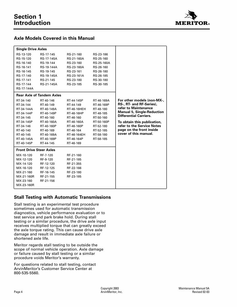
Axle Models Covered in this Manual
Stall Testing with Automatic Transmissions
Stall testing is an experimental test procedure sometimes used for automatic transmission diagnostics, vehicle performance evaluation or to test service and park brake hold. During stall testing or a similar procedure, the drive axle input receives multiplied torque that can greatly exceed the axle torque rating. This can cause drive axle damage and result in immediate axle failure or shortened axle life.
Meritor regards stall testing to be outside the scope of normal vehicle operation. Axle damage or failure caused by stall testing or a similar procedure voids Meritor’s warranty.
For questions related to stall testing, contact ArvinMeritor’s Customer Service Center at 800-535-5560.
Single Drive Axles
For other models (non-MX-, RS-, RT- and RF-Series), refer to MaintenanceManual 5, Single-Reduction Differential Carriers.
To obtain this publication, refer to the Service Notes page on the front inside cover of this manual.
RS-13-120RS-15-120RS-16-140RS-16-141RS-16-145RS-17-140RS-17-141RS-17-144RS-17-144A
RS-17-145RS-17-145ARS-19-144RS-19-144ARS-19-145RS-19-145ARS-21-145RS-21-145A
RS-21-160RS-21-160ARS-23-160RS-23-160ARS-23-161RS-23-161ARS-23-180RS-23-185
RS-23-186RS-25-160RS-25-160ARS-26-160RS-26-180RS-26-185RS-30-180RS-30-185
Rear Axle of Tandem Axles
RT-34-140RT-34-144RT-34-144ART-34-144PRT-34-145RT-34-145PRT-34-146RT-40-140RT-40-145RT-40-145ART-40-145P
RT-40-146RT-40-149RT-40-149ART-40-149PRT-40-160RT-40-160ART-40-160PRT-40-169RT-40-169ART-40-169PRT-44-145
RT-44-145PRT-44-149RT-46-16HEHRT-46-16HPRT-46-160RT-46-160ART-46-160PRT-46-164RT-46-164EHRT-46-164PRT-46-169
RT-46-169ART-46-169PRT-48-180RT-48-185RT-50-160RT-50-160PRT-52-180RT-52-185RT-58-180RT-58-185
Front Drive Steer Axles
MX-10-120MX-12-120MX-14-120MX-16-120MX-21-160MX-21-160RMX-23-160MX-23-160R
RF-7-120RF-9-120RF-12-120RF-12-125RF-16-145RF-21-155RF-21-156
RF-21-160RF-21-185RF-21-355RF-22-166RF-23-180RF-23-185

Section 2Removal and Disassembly
Maintenance Manual 5A Copyright 2003Revised 02-03 ArvinMeritor, Inc. Page 5
Section 2Removal and Disassembly
WARNING
To prevent serious eye injury, always wear safe eye protection when you perform vehicle maintenance or service.
Park the vehicle on a level surface. Block the wheels to prevent the vehicle from moving. Support the vehicle with safety stands. Do not work under a vehicle supported only by jacks. Jacks can slip and fall over. Serious personal injury can result.
Use a brass or leather mallet for assembly and disassembly procedures. Do not hit steel parts with a steel hammer. Pieces of a part can break off and cause serious personal injury.
Removal
Differential Carrier from the Axle Housing
NOTE:
If the vehicle is equipped with a driver-controlled main differential lock, the DCDL collar must be engaged before removing axle shafts. Refer to complete instructions under Driver-Controlled Main Differential Lock Assembly and
Figure 5.1
.
1. Park the vehicle on a level surface. Block the wheels to prevent the vehicle from moving.
Figure 2.1
.
2. Use a jack or other lifting tool to raise the vehicle so that the wheels to be serviced are off the ground. Support the vehicle with safety stands.
Figure 2.1
.
3. Place a drain pan under the rear axle.
4. Remove the plug from bottom of axle housing. Drain lubricant from the assembly.
5. Disconnect the driveline universal joint from the pinion input yoke or flange on the carrier.
Figure 2.2
.
Figure 2.1
1 SAFETY STANDS
1
Figure 2.2
1 FULL ROUND BEARING CUPS
2 END YOKE3 YOKE SADDLE4 WELD YOKE5 BEARING STRAP6 CAPSCREWS7 EASY-SERVICE
BEARING CUPS8 U-JOINT CROSS9 SLIP YOKE10 CAPSCREWS11 END YOKE12 WELD YOKE
13 SLIP YOKE14 U-JOINT CROSS15 CAPSCREWS16 END YOKE17 WELD YOKE18 SLIP YOKE19 U-JOINT CROSS20 CAPSCREWS21 END YOKE22 SLIP YOKE23 TUBING24 U-JOINT CROSS25 WELD YOKE
12
13
11
14
10
7
8
6
45
1
2
3
9
16
15
17
18
19
EASY SERVICETM
WING SERIESPERMALUBETM
FULL-ROUND
“RPL” SERIES,PERMALUBETM
2324 22
202125

Section 2Removal and Disassembly
Copyright 2003 Maintenance Manual 5APage 6 ArvinMeritor, Inc. Revised 02-03
6. Remove the capscrews and washers or stud nuts and washers, if equipped, from the flanges of both axle shafts.
7. Loosen the tapered dowels, if equipped, in the axle flanges of both axle shafts using one of the following methods.
Brass Drift Method
WARNING
Do not strike the round driving lugs on the flange of an axle shaft. Pieces can break off and cause serious personal injury.
1. Hold a 1-1/2-inch diameter brass drift or brass hammer against the center of the axle shaft, inside the round driving lugs.
Figure 2.3
.
2. Strike the end of the drift with a large hammer, five to six pounds, and the axle shaft and tapered dowels will loosen.
3. Mark each axle shaft before it is removed from the axle assembly.
4. Remove the tapered dowels and separate the axle shafts from the main axle hub assembly.
Figure 2.4
.
5. Install a cover over the open end of each axle assembly hub where an axle shaft was removed.
Air Hammer Vibration Method
WARNING
Wear safe eye protection when using an air hammer. When using power tools, axle components can loosen and break off causing serious personal injury.
CAUTION
Do not use a chisel or wedge to loosen the axle shaft and tapered dowels. Using a chisel or wedge can result in damage to the axle shaft, the gasket and seal, and the axle hub.
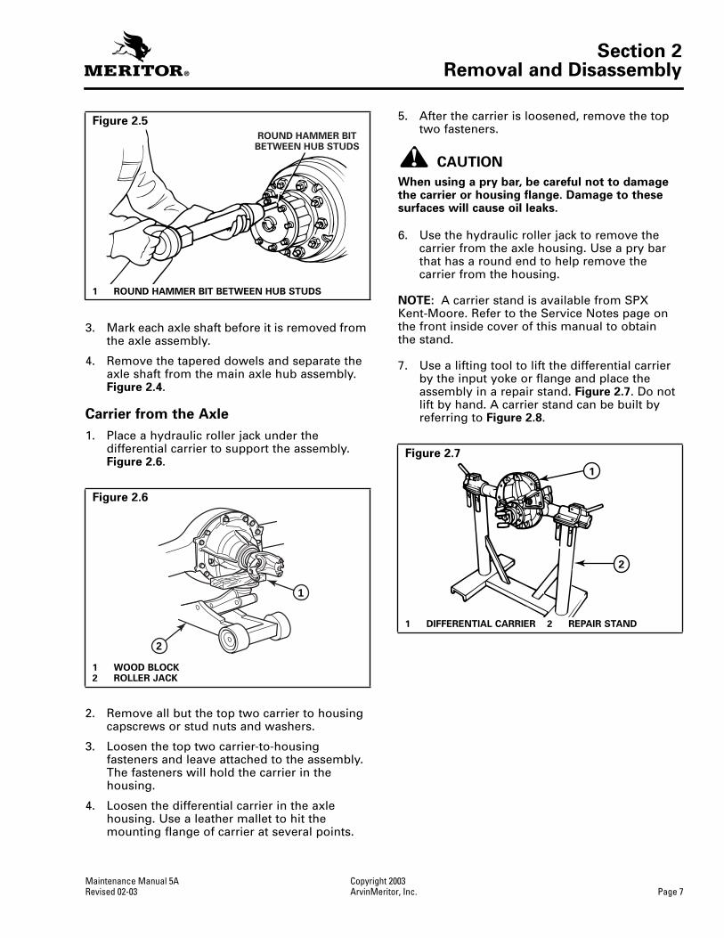
1. Use a round hammer bit and an air hammer to loosen tapered dowels and axle shaft.
2. Place the round hammer bit against the axle shaft or flange between the hub studs. Operate the air hammer at alternate locations between the studs to loosen the tapered dowels and axle shaft from the hub.
Figure 2.5
.
Figure 2.3
1 BRASS HAMMER2 DRIVING LUGS
1
2
Figure 2.4
1 STUD NUT2 WASHER3 TAPERED DOWEL4 GASKET5 STUD6 SHAFT HUB AXLE7 AXLE SHAFT OR FLANGE8 WASHER9 CAPSCREW
786
4 51
2 3
9
Section 2Removal and Disassembly
Maintenance Manual 5A Copyright 2003Revised 02-03 ArvinMeritor, Inc. Page 7
3. Mark each axle shaft before it is removed from the axle assembly.
4. Remove the tapered dowels and separate the axle shaft from the main axle hub assembly.
Figure 2.4
.
Carrier from the Axle
1. Place a hydraulic roller jack under the differential carrier to support the assembly.
Figure 2.6
.
2. Remove all but the top two carrier to housing capscrews or stud nuts and washers.
3. Loosen the top two carrier-to-housing fasteners and leave attached to the assembly. The fasteners will hold the carrier in the housing.
4. Loosen the differential carrier in the axle housing. Use a leather mallet to hit the mounting flange of carrier at several points.
5. After the carrier is loosened, remove the top two fasteners.
CAUTION
When using a pry bar, be careful not to damage the carrier or housing flange. Damage to these surfaces will cause oil leaks.
6. Use the hydraulic roller jack to remove the carrier from the axle housing. Use a pry bar that has a round end to help remove the carrier from the housing.
NOTE:
A carrier stand is available from SPX Kent-Moore. Refer to the Service Notes page on the front inside cover of this manual to obtainthe stand.
7. Use a lifting tool to lift the differential carrier by the input yoke or flange and place the assembly in a repair stand.
Figure 2.7
. Do not lift by hand. A carrier stand can be built by referring to
Figure 2.8
.
Figure 2.5
1 ROUND HAMMER BIT BETWEEN HUB STUDS
Figure 2.6
1 WOOD BLOCK2 ROLLER JACK
ROUND HAMMER BITBETWEEN HUB STUDS
1
2
Figure 2.7
1 DIFFERENTIAL CARRIER 2 REPAIR STAND
1
2

Section 2Removal and Disassembly
Copyright 2003 Maintenance Manual 5APage 8 ArvinMeritor, Inc. Revised 02-03
Figure 2.8
1 PLATES 8’ LONG x 3/4” THICK x 1-1/4” WIDE WITH A TONGUE TO FIT SLOT IN BAR WELD PLATES TO BAR
2 HANDLE 7” LONG WITH SLOT IN ONE END TO FIT CLAMP SCREW3 BAR 2” DIAMETER X 9” LONG WITH ONE END SLOTTED TO FIT PLATE4 WELD ALL AROUND AFTER PRESSING PLUG IN PIPE5 WELD6 SHAPE AND SIZE OF HOLES TO FIT CARRIER7 23-1/2” CENTER TO CENTER OF PIPE8 CHAMFER END OF PIPE FOR WELDING9 4” DIAMETER PIPE10 PLUG 4” DIAMETER x 7” LONG WITH ONE END TURNED 3” LONG TO FIT PIPE
DRILL 2” HOLE AND MILL 3/16” WIDE SLOT 2” FROM TOP11 SCREW 3-1/2” LONG x 5/8” DIAMETER WITH FLATS ON END TO FIT HANDLE AND
2-1/2” LENGTH OF THREAD ON OTHER END12 DRILL 3/8” HOLE THROUGH HANDLE AND SCREW
CARRIER STAND
21
4
3
6
5
8
7
10
9
12
11
SPX Kent-Moore
part number J-3409-D

Section 2Removal and Disassembly
Maintenance Manual 5A Copyright 2003Revised 02-03 ArvinMeritor, Inc. Page 9
Differential and Ring Gear from the Carrier
NOTE:
Before working on the differential carrier, inspect the hypoid gear set for damage. If inspection shows no damage, the same gear set can be used again. Measure the backlash of the gear set and make a record of the dimension.
Figure 2.9
. Refer to Section 4.
1. Loosen the jam nut on the thrust screw, if equipped.
2. Remove the thrust screw and jam nut, if equipped, from the differential carrier.
Figures 2.10 and 2.11
.
3. Rotate the differential carrier in the repair stand until the ring gear is at the top ofthe assembly.
4. Mark one carrier leg and bearing cap to correctly match the parts during carrier assembly. Mark the parts using a center punch and hammer. Figure 2.12.
Figure 2.9
1 DIAL INDICATOR
Figure 2.10
1
Figure 2.11
1 THRUST SCREW AND JAM NUT
Figure 2.12
1 BEARING CAP2 CARRIER LEG3 MATCH MARKS
1
1
2
3

Section 2Removal and Disassembly
Copyright 2003 Maintenance Manual 5APage 10 ArvinMeritor, Inc. Revised 02-03
5. Remove the cotter keys, pins or lock plates, if equipped, that hold the bearing adjusting rings in position. Use a small drift and hammer to remove pins. Each lock plate is held in position by two capscrews. Figure 2.13.
6. Remove the capscrews and washers that hold the two bearing caps on the carrier. Each cap is held in position by two capscrews and washers. Figure 2.14.
7. Remove the bearing caps and bearing adjusting rings from the carrier. Figure 2.15.
8. Safely lift the main differential and ring gear assembly from the carrier. Place the assembly on a work bench. Figure 2.16.
Disassembly
Differential and Ring Gear Assembly
WARNING
Observe all warnings and cautions provided by the press manufacturer to avoid damage to components and serious personal injury.
1. If the match marks on the case halves of the differential assembly are not visible, mark each case half with a center punch and hammer. Figure 2.17.
2. Remove the capscrews and washers or bolts, nuts and washers, if equipped, that hold the case halves together.
Figure 2.13
1 REMOVING COTTER KEY2 REMOVING LOCK PLATE
Figure 2.14
1 BEARING CAP
1 2
1
Figure 2.15
1 BEARING CAP2 BEARING ADJUSTING RING
Figure 2.16
1
2

Section 2Removal and Disassembly
Maintenance Manual 5A Copyright 2003Revised 02-03 ArvinMeritor, Inc. Page 11
3. Separate the case halves. If necessary, usea brass, plastic or leather mallet to loosen the parts.
4. Remove the differential spider or cross, four pinion gears, two side gears and six thrust washers from inside the case halves. Figure 2.18.
5. If the ring gear needs to be replaced, remove the bolts, nuts, and washers, if equipped, that hold the gear to the flange case half.
CAUTION
Do not remove the rivets or rivet heads with a chisel and hammer. Using a flat edge tool can cause damage to the flange case.
6. If rivets hold the ring gear to the flange case half, remove the rivets as follows.
A. Carefully center punch each rivet head in the center, on the ring gear side of the assembly. Do not use a chisel and hammer. Figure 2.19.
B. Drill each rivet head on the ring gear side of the assembly to a depth equal to the thickness of one rivet head. Use a drill bit that is 0.03125-inch (0.79375 mm) smaller than the body diameter of the rivets. Figure 2.19.
C. Press the rivets through holes in the ring gear and flange case half. Press from the drilled rivet head.
Figure 2.17
1 MATCH MARKS
Figure 2.18
1 THRUST WASHER2 SIDE GEAR3 SPIDER, PINIONS AND THRUST WASHERS
1
1
1
1
23
1003000a
Figure 2.19
1 CORRECT DRILLING RIVETS FROM HEAD2 WRONG CHISELING RIVETS FROM HEAD
1003001a
1 2

Section 2Removal and Disassembly
Copyright 2003 Maintenance Manual 5APage 12 ArvinMeritor, Inc. Revised 02-03
7. Use a press to separate the case half and ring gear. Support the assembly under the ring gear with metal or wood blocks. Press the case half through the gear. Figure 2.20.
8. If the differential bearings need to be replaced, use a bearing puller or press to remove the bearing cones from the case halves. Figure 2.21.
Removal
Drive Pinion and Bearing Cage from the Carrier
1. Fasten a flange bar to the input yoke or flange. When the nut is removed, the bar will hold the drive pinion in position. Figure 2.22.
2. Remove the nut and washer, if equipped, from the drive pinion. Figure 2.22.
3. Remove the yoke or flange bar.
CAUTION
Do not use a hammer or mallet to loosen and remove the yoke or flange. A hammer or mallet can damage the parts and cause driveline runout, or driveline imbalance problems after carrier to driveline assembly.
4. Remove the yoke or flange from the drive pinion. Do not use a hammer or mallet.
O If the yoke or flange is tight on the pinion: Use a puller for removal. Figure 2.23.
5. Remove the capscrews and washers that hold the bearing cage in the carrier. Figure 2.24.
Figure 2.20
1 CASE HALF2 PRESS3 PLATE4 SUPPORTS
Figure 2.21
1
2
3
1003002b
4
PULLER
PRESS
Figure 2.22
1 FLANGE BAR2 YOKE BAR
2
1

Section 2Removal and Disassembly
Maintenance Manual 5A Copyright 2003Revised 02-03 ArvinMeritor, Inc. Page 13
CAUTION
Do not use a pry bar to remove the bearing cage from the carrier. A pry bar can damage the bearing case, shims and carrier.
6. Remove the drive pinion, bearing cage and shims from the carrier. Do not use a pry bar.
O If the bearing cage is tight in the carrier: Hit the bearing cage at several points around the flange area with a leather, plastic or rubber mallet. Figure 2.25.
7. If the shims are in good condition, keep the shims together to use when the carrieris assembled.
8. If shims are to be discarded because of damage, first measure the total thickness of the pack. Make a note of the dimension.The dimension will be needed to calculate the depth of the drive pinion in the carrier when the gear set is installed.
Figure 2.23
Figure 2.24
1 BEARING CAGE2 CARRIER
YOKE PULLER
FLANGE PULLER
1003350a
1
2
Figure 2.25
1 DRIVE PINION AND BEARING CAGE2 SHIMS
1
2

Section 2Removal and Disassembly
Copyright 2003 Maintenance Manual 5APage 14 ArvinMeritor, Inc. Revised 02-03
Disassembly
Drive Pinion and Bearing Cage
WARNING
Observe all warnings and cautions provided by the press manufacturer to avoid damage to components and serious personal injury.
1. Place the drive pinion and bearing cage in a press. The pinion shaft must be toward the top of the assembly. Figure 2.27.
2. Support the bearing cage under the flange area with metal or wood blocks. Figure 2.27.
3. Press the drive pinion through the bearing cage. The inner bearing cone and bearing spacer will remain on the pinion shaft. Figure 2.27.
O If a press is not available: Use a leather, plastic or rubber mallet to drive the pinion through the bearing cage.
CAUTION
Be careful when removing the seal. Do not damage the wall of bore. Damage to the bore wall can result in oil leaks.
4. Use a press and a sleeve to remove the triple-lip or unitized oil seal from the bearing cage.
O If a press is not available: Place a tool with a flat blade under the flange to remove the oil seal from the cage. Figure 2.28.
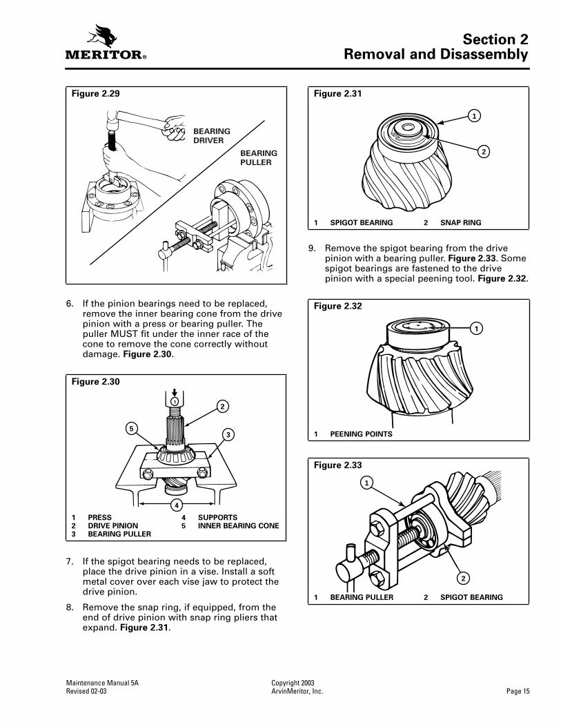
5. If the pinion bearings need to be replaced, remove the inner and outer bearing cups from the inside of cage. Use a press and sleeve, bearing puller or a small drift hammer. The type of tool used depends on the design of the bearing cage. Figure 2.29.
When a press is used, support the bearing cage under the flange area with metal orwood blocks.
Figure 2.26
1 DRIVE PINION2 OIL SEAL3 OUTER BEARING, CUP
AND CONE4 INNER BEARING, CUP AND
CONE
5 SPIGOT BEARING6 SNAP RING7 BEARING SPACER
Figure 2.27
1 PRESS2 DRIVE PINION3 OIL SEAL4 BEARING CAGE
5 SUPPORT6 SPIGOT BEARING7 SUPPORT
7
6
4
5
1 2
3
7 6
4
5
1
2
3
Figure 2.28
1002437a
Section 2Removal and Disassembly
Maintenance Manual 5A Copyright 2003Revised 02-03 ArvinMeritor, Inc. Page 15
6. If the pinion bearings need to be replaced, remove the inner bearing cone from the drive pinion with a press or bearing puller. The puller MUST fit under the inner race of the cone to remove the cone correctly without damage. Figure 2.30.
7. If the spigot bearing needs to be replaced, place the drive pinion in a vise. Install a soft metal cover over each vise jaw to protect the drive pinion.
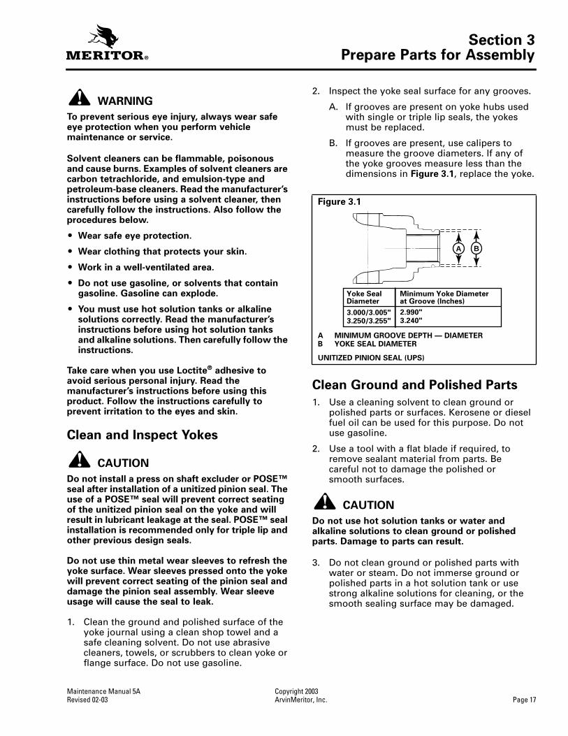
8. Remove the snap ring, if equipped, from the end of drive pinion with snap ring pliers that expand. Figure 2.31.
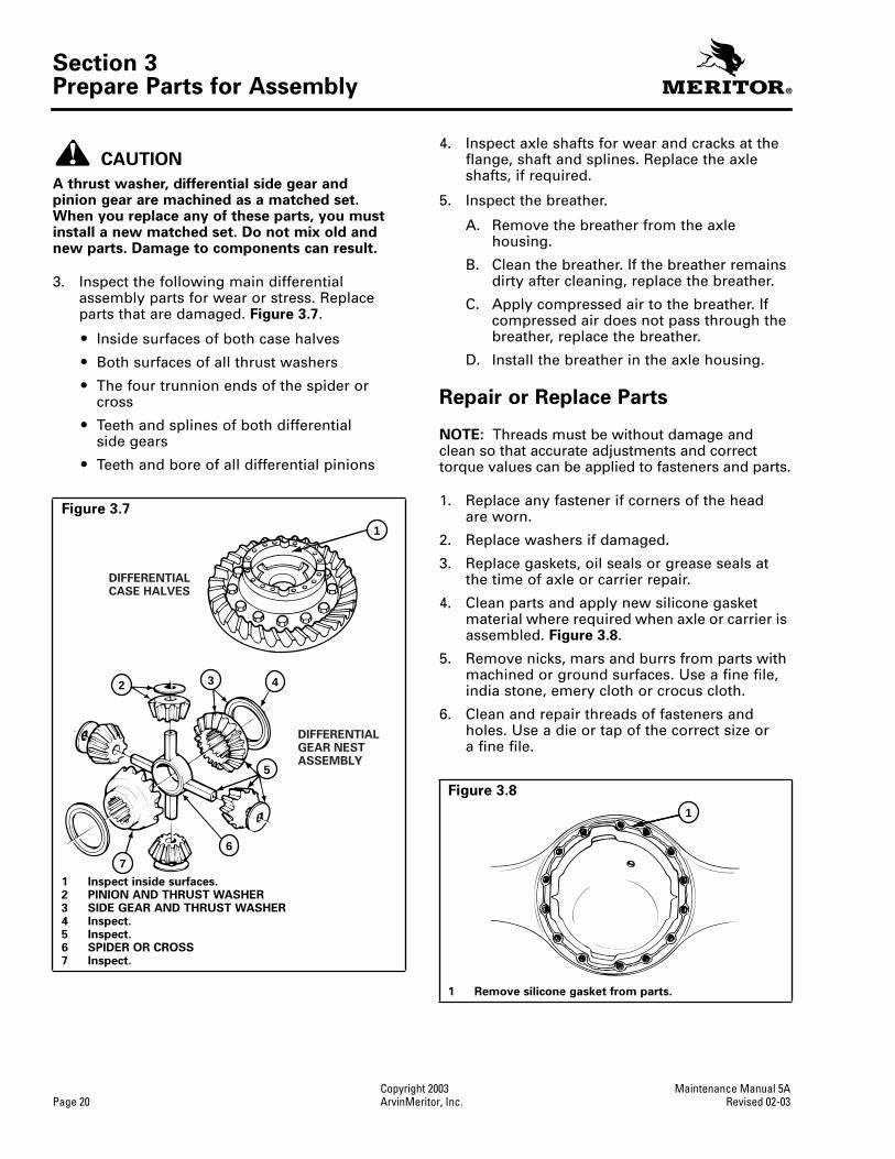
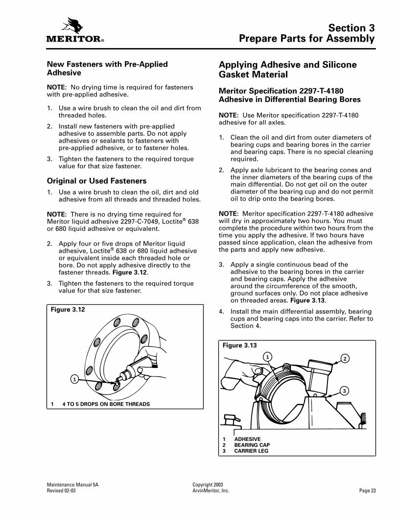
9. Remove the spigot bearing from the drive pinion with a bearing puller. Figure 2.33. Some spigot bearings are fastened to the drive pinion with a special peening tool. Figure 2.32.
Figure 2.29
Figure 2.30
1 PRESS2 DRIVE PINION3 BEARING PULLER
4 SUPPORTS5 INNER BEARING CONE
BEARING
DRIVER
BEARING
PULLER
1
4
2
53
Figure 2.31
1 SPIGOT BEARING 2 SNAP RING
Figure 2.32
1 PEENING POINTS
Figure 2.33
1 BEARING PULLER 2 SPIGOT BEARING
1
2
1
1
2

Section 2Removal and Disassembly
Copyright 2003 Maintenance Manual 5APage 16 ArvinMeritor, Inc. Revised 02-03
10. If the spigot bearings are a two-piece assembly, remove the inner race from the pinion with a bearing puller. Remove the outer race and roller assembly from the carrier with a drift or a press. Figure 2.34.
Figure 2.34
1 Remove outer race and roller assembly from carrier.2 Remove inner race from pinion.
1
2
Section 3Prepare Parts for Assembly
Maintenance Manual 5A Copyright 2003Revised 02-03 ArvinMeritor, Inc. Page 17
Section 3Prepare Parts for Assembly
WARNING
To prevent serious eye injury, always wear safe eye protection when you perform vehicle maintenance or service.
Solvent cleaners can be flammable, poisonous and cause burns. Examples of solvent cleaners are carbon tetrachloride, and emulsion-type and petroleum-base cleaners. Read the manufacturer’s instructions before using a solvent cleaner, then carefully follow the instructions. Also follow the procedures below.
O Wear safe eye protection.
O Wear clothing that protects your skin.
O Work in a well-ventilated area.
O Do not use gasoline, or solvents that contain gasoline. Gasoline can explode.
O You must use hot solution tanks or alkaline solutions correctly. Read the manufacturer’s instructions before using hot solution tanks and alkaline solutions. Then carefully follow the instructions.
Take care when you use Loctite® adhesive to avoid serious personal injury. Read the manufacturer’s instructions before using this product. Follow the instructions carefully to prevent irritation to the eyes and skin.
Clean and Inspect Yokes
CAUTION
Do not install a press on shaft excluder or POSE™ seal after installation of a unitized pinion seal. The use of a POSE™ seal will prevent correct seating of the unitized pinion seal on the yoke and will result in lubricant leakage at the seal. POSE™ seal installation is recommended only for triple lip and other previous design seals.
Do not use thin metal wear sleeves to refresh the yoke surface. Wear sleeves pressed onto the yoke will prevent correct seating of the pinion seal and damage the pinion seal assembly. Wear sleeve usage will cause the seal to leak.
1. Clean the ground and polished surface of the yoke journal using a clean shop towel and a safe cleaning solvent. Do not use abrasive cleaners, towels, or scrubbers to clean yoke or flange surface. Do not use gasoline.
2. Inspect the yoke seal surface for any grooves.
A. If grooves are present on yoke hubs used with single or triple lip seals, the yokes must be replaced.
B. If grooves are present, use calipers to measure the groove diameters. If any of the yoke grooves measure less than the dimensions in Figure 3.1, replace the yoke.
Clean Ground and Polished Parts
1. Use a cleaning solvent to clean ground or polished parts or surfaces. Kerosene or diesel fuel oil can be used for this purpose. Do not use gasoline.
2. Use a tool with a flat blade if required, to remove sealant material from parts. Be careful not to damage the polished or smooth surfaces.
CAUTION
Do not use hot solution tanks or water and alkaline solutions to clean ground or polished parts. Damage to parts can result.
3. Do not clean ground or polished parts with water or steam. Do not immerse ground or polished parts in a hot solution tank or use strong alkaline solutions for cleaning, or the smooth sealing surface may be damaged.
Figure 3.1
A MINIMUM GROOVE DEPTH — DIAMETERB YOKE SEAL DIAMETER
UNITIZED PINION SEAL (UPS)
Yoke SealDiameter
3.000/3.005"3.250/3.255"
Minimum Yoke Diameter at Groove (Inches)
2.990"3.240"
A B

Section 3Prepare Parts for Assembly
Copyright 2003 Maintenance Manual 5APage 18 ArvinMeritor, Inc. Revised 02-03
Clean Rough Parts
1. Clean rough parts with the same method as cleaning ground and polished parts.
2. Rough parts can be cleaned in hot solution tanks with a weak or diluted alkaline solution.
3. Parts must remain in hot solution tanks until heated and completely cleaned.
4. Parts must be washed with water until all traces of the alkaline solution are removed.
Clean Axle Assemblies
1. A complete axle assembly can be steam cleaned on the outside to remove dirt.
2. Before the axle is steam cleaned, close or place a cover over all openings in the axle assembly. Examples of openings are breathers or vents in air chambers.
Dry Parts After Cleaning
1. Parts must be dried immediately after cleaning and washing.
2. Dry the parts using soft, clean paper or cloth rags.
CAUTION
Damage to bearings can result when they are rotated and dried with compressed air.
3. Except for bearings, parts can be dried with compressed air.
Prevent Corrosion on Cleaned Parts
1. Apply axle lubricant to cleaned and dried parts that are not damaged and are to be assembled.
2. To store parts, apply a special material that prevents corrosion to all surfaces. Wrap cleaned parts in a special paper that will protect the parts from moisture and prevent corrosion.
Inspect Parts
It is very important to inspect all parts carefully and completely before the axle or carrier is assembled. Check all parts for wear and replace damaged parts.
1. Inspect the cup, cone, rollers and cage of all tapered roller bearings in the assembly. If any of the following conditions exist, replace the bearing.
O The center of the large-diameter end of the rollers is worn level with or below the outer surface. Figure 3.2.
O The radius at the large-diameter end of the rollers is worn to a sharp edge. Figure 3.2.
O There is a visible roller groove in the cup or cone inner race surfaces. The groove can be seen at the small- or large-diameter end of both parts. Figure 3.3.
O There are deep cracks or breaks in the cup, cone inner race or roller surfaces. Figure 3.3.
O There are bright wear marks on the outer surface of the roller cage. Figure 3.4.
O There is damage on the rollers and on the surfaces of the cup and cone inner race that touch the rollers. Figure 3.5.
O There is damage on the cup and cone inner race surfaces that touch the rollers. Figure 3.6.
Figure 3.2
1 WORN RADIUS2 WORN SURFACE
1003017a2
1

Section 3Prepare Parts for Assembly
Maintenance Manual 5A Copyright 2003Revised 02-03 ArvinMeritor, Inc. Page 19
CAUTION
A drive pinion and ring gear are machined as a matched set. When you replace either a drive pinion or a ring gear, you must replace both parts as a matched set. Do not mix old and new parts. Damage to components can result.
2. Inspect hypoid pinions and gears for wear and damage. Replace gears that are worn or damaged.
Figure 3.3
1 CRACK2 WEAR GROOVE
Figure 3.4
1 WEAR MARKS
Figure 3.5
1 ETCHING AND PITTING
21
4000907
WEAR MARKS
1003020a
ETCHING AND PITTING
Figure 3.6
1 SPALLING AND FLAKING
1
Section 3Prepare Parts for Assembly
Copyright 2003 Maintenance Manual 5APage 20 ArvinMeritor, Inc. Revised 02-03
CAUTION
A thrust washer, differential side gear and pinion gear are machined as a matched set. When you replace any of these parts, you must install a new matched set. Do not mix old and new parts. Damage to components can result.
3. Inspect the following main differential assembly parts for wear or stress. Replace parts that are damaged. Figure 3.7.
O Inside surfaces of both case halves
O Both surfaces of all thrust washers
O The four trunnion ends of the spider or cross
O Teeth and splines of both differential side gears
O Teeth and bore of all differential pinions
4. Inspect axle shafts for wear and cracks at the flange, shaft and splines. Replace the axle shafts, if required.
5. Inspect the breather.
A. Remove the breather from the axle housing.
B. Clean the breather. If the breather remains dirty after cleaning, replace the breather.
C. Apply compressed air to the breather. If compressed air does not pass through the breather, replace the breather.
D. Install the breather in the axle housing.
Repair or Replace Parts
NOTE: Threads must be without damage and clean so that accurate adjustments and correct torque values can be applied to fasteners and parts.
1. Replace any fastener if corners of the head are worn.
2. Replace washers if damaged.
3. Replace gaskets, oil seals or grease seals at the time of axle or carrier repair.
4. Clean parts and apply new silicone gasket material where required when axle or carrier is assembled. Figure 3.8.
5. Remove nicks, mars and burrs from parts with machined or ground surfaces. Use a fine file, india stone, emery cloth or crocus cloth.
6. Clean and repair threads of fasteners and holes. Use a die or tap of the correct size ora fine file.
Figure 3.7
1 Inspect inside surfaces.2 PINION AND THRUST WASHER3 SIDE GEAR AND THRUST WASHER4 Inspect.5 Inspect.6 SPIDER OR CROSS7 Inspect.
1
7
6
4
5
2 3
DIFFERENTIALCASE HALVES
DIFFERENTIALGEAR NEST ASSEMBLY
Figure 3.8
1 Remove silicone gasket from parts.
1

Section 3Prepare Parts for Assembly
Maintenance Manual 5A Copyright 2003Revised 02-03 ArvinMeritor, Inc. Page 21
Repair Welding on Axle Housings
For Complete Welding Instructions on Meritor Drive Axle Housings
WARNING
Wear safe clothing and eye protection when you use welding equipment. Welding equipment can burn you and cause serious personal injury. Follow the operating instructions and safety procedures recommended by the welding equipment manufacturers.
Axle weld locations and welding procedures must adhere to Meritor‘s standards. Welding at locations other than those authorized by Meritor will void the warranty and can reduce axle beam fatigue life. Serious personal injury and damage to components can result.
Refer to Maintenance Manual 8, Drive Axle Housings. To obtain this publication, refer to the Service Notes page on the front inside cover of this manual.
Meritor permits drive axle housing assembly repair welding in the following locations only.
O Housing-to-cover weld joints
O Snorkel welds
O Housing seam welds between the suspension attaching brackets
O Bracket welding to the drive axle housing
Prepare the Axle
WARNING
The high temperature caused by the open flame from the cutting torch can ignite the oil in the axle housing and can cause serious personal injury.
1. Remove the oil drain plug from the bottom of the axle housing and drain the lubricant from the assembly.
CAUTION
Remove the differential carrier from the axle housing before you weld onto an axle. Do not weld onto an axle with the differential carrier installed. Electrical arching and damage to components can result.
2. Remove the differential carrier from the axle housing. Refer to the correct Meritor carrier maintenance manual or the vehicle manufacturer’s instructions.
CAUTION
Remove the brake air chambers before you weld onto an axle. Do not expose a brake air chamber to more than 250°F (121°C). Damage to the air chamber can result.
3. Remove the wheel-end components and brake air chambers from the axle. Refer to the correct Meritor brake maintenance manual or the vehicle manufacturer’s instructions.
4. For housing-to-cover welds, clean the outside housing-to-cover weld area 2.00-3.00-inches (50.8-76.2 mm) past each end or side of the crack. Clean the inside area where the cover mates with the housing. Clean the area completely around the cover. Use a wire brush and a cleaning solvent that will remove dirt and grease from these areas. Figure 3.9.
Figure 3.9
1 Clean this area.
1

Section 3Prepare Parts for Assembly
Copyright 2003 Maintenance Manual 5APage 22 ArvinMeritor, Inc. Revised 02-03
5. For suspension bracket welds, clean both lower and upper suspension brackets and the areas of the axle housing around each bracket. Use a wire brush and a cleaning solvent that will remove dirt and grease from these areas. Figures 3.10 and 3.11.
WARNING
The axle housing must be 70°F (21°C) or warmer before you weld onto the axle. Do not weld onto a cold axle or weld cold parts onto an axle. Cracks in the weld area, damage to components and serious personal injury can result.
6. Ensure that the axle housing temperature measures 70°F (21°C) or warmer.
O If the axle housing temperature measures less than 70°F (21°C): Store the axle in a heated room until the housing reaches the correct temperature.
7. Heat the damaged area to approximately 300°F (149°C) before you begin welding.
8. Use suitable weld wire electrodes when you weld. Suitable weld wire electrodes include either BS EN 499 – E 42 2 B 32 H5 or BS EN 440 – G 42 2 M GSi (American Welding Society equivalents E7018 and ER70S3, respectively).
9. For complete welding instructions, refer to Maintenance Manual 8. To obtain this publication, refer to the Service Notes page on the front inside cover of this manual.
Do Not Bend or Straighten a Damaged Drive Axle Housing
WARNING
Replace damaged or out-of-specification axle components. Do not bend, repair or recondition axle components by welding or heat-treating. A bent axle beam reduces axle strength, affects vehicle operation and voids Meritor’s warranty. Serious personal injury and damage to components can result.
Always replace a damaged drive axle housing. Do not bend or straighten a damaged housing, which can misalign or weaken it, and void Meritor’s warranty.
Fasteners
Removing Fasteners Secured with Adhesive
If it is difficult to remove fasteners secured with Dri-Loc®, Meritor adhesive or Loctite® 277 adhesive, use the following procedure.
When you remove fasteners secured with adhesive, slowly heat the fastener to 350°F (177°C). Do not exceed this temperature, or heat fasteners quickly. Damage to components can result.
1. Heat the fastener for three to five seconds. Try to loosen the fastener with a wrench. Do not use an impact wrench or hit the fastener with a hammer.
2. Repeat Step 1 until you can remove the fastener.
Figure 3.10
1 Clean these areas.2 LOWER BRACKET
Figure 3.11
1 Clean these areas.2 Clean this area.3 UPPER BRACKET
1
2
2
1
3
Section 3Prepare Parts for Assembly
Maintenance Manual 5A Copyright 2003Revised 02-03 ArvinMeritor, Inc. Page 23
New Fasteners with Pre-Applied Adhesive
NOTE: No drying time is required for fasteners with pre-applied adhesive.
1. Use a wire brush to clean the oil and dirt from threaded holes.
2. Install new fasteners with pre-applied adhesive to assemble parts. Do not apply adhesives or sealants to fasteners with pre-applied adhesive, or to fastener holes.
3. Tighten the fasteners to the required torque value for that size fastener.
Original or Used Fasteners
1. Use a wire brush to clean the oil, dirt and old adhesive from all threads and threaded holes.
NOTE: There is no drying time required for Meritor liquid adhesive 2297-C-7049, Loctite® 638 or 680 liquid adhesive or equivalent.
2. Apply four or five drops of Meritor liquid adhesive, Loctite® 638 or 680 liquid adhesive or equivalent inside each threaded hole or bore. Do not apply adhesive directly to the fastener threads. Figure 3.12.
3. Tighten the fasteners to the required torque value for that size fastener.
Applying Adhesive and Silicone Gasket Material
Meritor Specification 2297-T-4180 Adhesive in Differential Bearing Bores
NOTE: Use Meritor specification 2297-T-4180 adhesive for all axles.
1. Clean the oil and dirt from outer diameters of bearing cups and bearing bores in the carrier and bearing caps. There is no special cleaning required.
2. Apply axle lubricant to the bearing cones and the inner diameters of the bearing cups of the main differential. Do not get oil on the outer diameter of the bearing cup and do not permit oil to drip onto the bearing bores.
NOTE: Meritor specification 2297-T-4180 adhesive will dry in approximately two hours. You must complete the procedure within two hours from the time you apply the adhesive. If two hours have passed since application, clean the adhesive from the parts and apply new adhesive.
3. Apply a single continuous bead of the adhesive to the bearing bores in the carrier and bearing caps. Apply the adhesive around the circumference of the smooth, ground surfaces only. Do not place adhesive on threaded areas. Figure 3.13.
4. Install the main differential assembly, bearing cups and bearing caps into the carrier. Refer to Section 4.
Figure 3.12
1 4 TO 5 DROPS ON BORE THREADS
1
Figure 3.13
1 ADHESIVE2 BEARING CAP3 CARRIER LEG
1 2
3

Section 3Prepare Parts for Assembly
Copyright 2003 Maintenance Manual 5APage 24 ArvinMeritor, Inc. Revised 02-03
5. Adjust preload of the differential bearings, backlash and tooth contact patterns of the gear set as required. Refer to Section 4.
Three Bond 1216, or Equivalent, Silicone Gasket Material
WARNING
When you apply some silicone gasket materials, a small amount of acid vapor is present. To prevent serious personal injury, ensure that the work area is well-ventilated. Read the manufacturer’s instructions before using a silicone gasket material, then carefully follow the instructions. If a silicone gasket material gets into your eyes, follow the manufacturer’s emergency procedures. Have your eyes checked by a physician as soon as possible.
NOTE: The following silicone gasket products or equivalent can be used for Meritor components:
O Three Bond Liquid Gasket TB 1216 (Grey)
O Loctite® Grey RTV 5699
O From Meritor: Ten-ounce tubes, part number 2297-F-7052
1. Use a tool with a flat blade, if required, to remove all old gasket material from surfaces. Figure 3.14.
2. Use a cleaning solvent to clean the surfaces where you will apply silicone gasket material. Remove all oil, grease, dirt and moisture without damaging the mating surfaces. Figure 3.14.
3. Dry surfaces.
CAUTION
Apply silicone gasket material in a continuous 0.125-inch (3 mm) bead. If you use more than this amount, gasket material can break off and plug lubrication passages. Damage to components can result.
4. Apply 0.125-inch (3 mm) diameter continuous bead of the silicone gasket material around one surface. Also apply the gasket material around the edge of all fastener holes on that surface. Figure 3.15.
5. Assemble the components immediately to permit the silicone gasket material to compress evenly between the parts. Tighten fasteners to the required torque value for that size fastener. Refer to Section 7.
6. Wait 20 minutes before filling the assembly with lubricant. Refer to Section 6.
Carrier-to-Housing Joint Repair
1. Remove the carrier from the housing. Refer to Section 2.
2. Remove all debris from inside the housing.
3. Use a rotary tool with a ScotchBriteTM pad to clean all silicone residue from the housing and carrier faces. Figure 3.16. Surfaces must be clean, dry and free of foreign matter. The surfaces must not be oily to the touch.
Figure 3.14
1 Remove old sealant material.
HOUSING AND CARRIER SHOWN
1
Figure 3.15
1 0.125” (3 MM) DIAMETER SILICONE GASKET BEAD
1

Section 3Prepare Parts for Assembly
Maintenance Manual 5A Copyright 2003Revised 02-03 ArvinMeritor, Inc. Page 25
4. Remove metal filings from the magnets inside the housing.
5. Use solvent to clean the inside of the housing.
6. Use Loctite
®
ODC Free cleaner or brake cleaner to clean the housing and carrier faces.
7. Dry the housing and carrier faces.
8. Use a rotary wire brush to remove any nylon patch material and clean the carrier-to-housing capscrew threads. Use a clean cloth to wipe the threads.
9. Use a tap to clean the internal threads in the housing.
WARNING
When you apply some silicone gasket materials, a small amount of acid vapor is present. To prevent serious personal injury, ensure that the work area is well-ventilated. Read the manufacturer’s instructions before using a silicone gasket material, then carefully follow the instructions. If a silicone gasket material gets into your eyes, follow the manufacturer’s emergency procedures. Have your eyes checked by a physician as soon as possible.
10. Apply a 0.25-inch (6 mm) bead of Loctite
®
5699 silicone gasket material to the housing face. Do not use Three Bond 1216E silicone products.
11. Install two long studs in the carrier to guide the carrier into the housing.
12. Immediately install the carrier into the housing to permit the silicone gasket material to compress evenly between the faces.
CAUTION
Apply silicone gasket material in a continuous 0.125-inch (3 mm) bead. If you use more than this amount, gasket material can break off and plug lubrication passages. Damage to components can result.
13. Apply a 0.125-inch (3 mm) bead of Loctite
®
242 threadlocker around the capscrew threads approximately 0.25-inch (6 mm) from the end. Apply a 0.125-inch (3 mm) bead of Loctite
®
242 threadlocker across the length of the threads.
Figure 3.17
.
14. Install the capscrews. Use a crossing pattern to tighten the capscrews evenly. The capscrews must be tightened within 10 minutes of initial application of Loctite
®
242 threadlocker.
O
Tighten 1/2-inch capscrews to 140 lb-ft (190 N•m).
O
Tighten 5/8-inch capscrews to 225 lb-ft(306 N•m).
15. Wait a minimum of 60 minutes before filling the assembly with lubricant. Refer toSection 6.
Figure 3.16
CLEANING HOUSING FACE WITH ROTARY TOOL AND SCOTCHBRITE™ PAD
Figure 3.17
1 360° LOCTITE
®
BEAD2 0.25" (6 MM)
LOCTITE
®
242 THREADLOCKER APPLICATION
1
2
T
T

Section 3Prepare Parts for Assembly
Copyright 2003 Maintenance Manual 5APage 26 ArvinMeritor, Inc. Revised 02-03
Installing Tight Fit Yokes andPOSE
TM
Seal
Refer to Figure 3.18
1. Apply the same lubricant used in the axle housing to the hub of the yoke or flange.
2. Inspect and verify that the lips of the POSE™ seal and the outer retainer of the triple-lip seal or main seal are clean and free from dirt and particles that may cause lubricant leakage between the seals.
3. Install the POSE
TM
seal on the hub of the yoke or flange by hand. The lips of the seal must face toward the end of the hub or the opposite shoulder. Slide the POSE
TM
seal on the hub until the lips are from 0.25-0.50-inch (6.4-12.7 mm) from the end of the hub. Do not install the POSE
TM
seal against the shoulder.
Figure 3.19
.
NOTE:
The POSE
TM
seal will position itself correctly as the yoke or flange is pressed on the shaft.
4. Before you install the yoke or flange on the shaft, apply the same lubricant used in the axle housing to the hub.
5. Install the yoke or flange using the correct procedure. The yoke must be completely seated before tightening the pinion nut to the input shaft.
Installing Any Type Yoke with a Unitized Pinion Seal (UPS)
CAUTION
Once the yoke is partially or fully installed and then removed for any reason, the unitized pinion seal will be damaged and unusable. If the yoke and unitized pinion seal are removed after partial or full installation, remove and discard the original unitized pinion seal and replace it with another new unitized pinion seal.
If the inner sleeve of the seal is removed, the seal is not usable. A new seal is required. This will occur if a yoke is installed into the seal and then removed.
1. Remove the replacement unitized seal from the package.
Figure 3.20
.
Figure 3.18
1 Lubricate triple-lip or main seal.2 INPUT SHAFT OR PINION3 POSE™ SEAL, 0.25-0.50” (6.4-12.7 MM) ONTO HUB4 Inspect yoke hub.
4
1
2
3
Figure 3.19
1 0.25-0.50” (6.4-12.7 MM)2 YOKE HUB3 FACE SEAL ASSEMBLY, POSE™ SEAL ELEMENT
Figure 3.20
UNITIZED SEAL
1
2
3

Section 3Prepare Parts for Assembly
Maintenance Manual 5A Copyright 2003Revised 02-03 ArvinMeritor, Inc. Page 27
2. Select the correct seal driver from
Table A
. Each seal driver is designed to correctly install a specific diameter seal. To determine the yoke seal diameter, measure the yoke journal. Refer to
Table A
on the following page.
3. Position the seal on the driver.
CAUTION
Use a rubber mallet to install the seal. Do not use a steel, brass or plastic hammer. Damage to the seal and driver tool can result.
4. Use a rubber mallet to drive the seal into or against the bearing cage. The seal must fully seat into or against the bearing cage.
Figure 3.21
.
5. Use a 0.010-inch shim to check for clearance between the entire seal flange circumference and the bearing cage.
O
If the 0.010-inch shim slides between the seal flange and bearing cage:
Correctly position the seal driver and drive the seal into the bore until the 0.010-inch shim cannot slide between the seal flange and bearing cage at any point around the seal flange.
Figure 3.22
.
Table A: Unitized Pinion Seals and Seal Drivers
Figure 3.21
1 RUBBER MALLET2 REFERENCE MARK3 SEAL DRIVER R4422401
The seal must fully seatinto or against the bearing cage.
1 2
3
Single Models Tandem ModelsMeritor Unitized Pinion Seal Seal Installation Location
Meritor Seal Driver
Yoke Seal Diameter Inches
MX-21-160MX-23-160RRF-16-145RF-21-160RF-22-166RF-23-185RS-17-145RS-19-145RS-21-145RS-21-160RS-23-160 /ARS-23-161 /ARS-25-160 /ARS-23-186RS-26-185RS-30-185
RT-34-144 /PRT-34-145 /PRT-40-145 /A /PRT-40-149 /A /PRT-44-145 /PRT-40-160 /A /PRT-40-169 /A /PRT-46-160 /A /PRT-46-169 /A /PRT-46-164EH /PRT-46-16HEH /PRT-50-160 /PRT-52-185*RT-58-185*
A-1205-R-2592 Tandem Forward Input — 145 models from 11/93 to present
R4422402 3.2503.255
A-1205-P-2590 Tandem Forward Output — Tandem Forward Input 145 models before 11/93 with seal A-1205-F-2424
R4422401 3.0003.005
A-1205-N-2588 Tandem and Single Rear Input — 145 models
R4422401 3.0003.005
A-1205-Q-2591 Tandem and Single Rear Input — 160/164/185 models
R4422402 3.2503.255
To obtain Meritor seal driver KIT 4454, refer to the Service Notes page on the front inside cover of this manual.
* Forward and rear input only.

Section 3Prepare Parts for Assembly
Copyright 2003 Maintenance Manual 5APage 28 ArvinMeritor, Inc. Revised 02-03
Clean, Inspect and Install the Yoke After Installing a Unitized Pinion Seal
WARNING
Solvent cleaners can be flammable, poisonous and cause burns. Examples of solvent cleaners are carbon tetrachloride, and emulsion-type and petroleum-base cleaners. Read the manufacturer’s instructions before using a solvent cleaner, then carefully follow the instructions. Also follow the procedures below.
O
Wear safe eye protection.
O
Wear clothing that protects your skin.
O
Work in a well-ventilated area.
O
Do not use gasoline, or solvents that contain gasoline. Gasoline can explode.
O
You must use hot solution tanks or alkaline solutions correctly. Read the manufacturer’s instructions before using hot solution tanks and alkaline solutions. Then carefully follow the instructions.
1. Use a clean shop towel and a safe cleaning solvent to clean the ground and polished surface of the yoke journal. Do not use gasoline, abrasive cleaners, towels, or scrubbers to clean the yoke. Do not attempt to polish the yoke.
NOTE:
The unitized seal features a rubber inner sleeve that is designed to seal and rotate with the yoke. This feature allows you to reuse a yoke with minor grooves.
2. Inspect the yoke seal surface for grooves.
O
If you find grooves on the yoke:
Use calipers to measure the groove diameters. If any groove diameter measures less than the dimensions shown in
Figure 3.23
, replace the yoke.
CAUTION
Do not install a POSE™ seal after you install a unitized pinion seal. The use of a POSE™ seal will prevent correct seating of the unitized pinion seal on the yoke and can result in lubricant leakage at the seal. POSE™ seal installation is recommended only for triple lip and other previous design seals.
Do not use thin metal wear sleeves to refresh the yoke surface. Wear sleeves pressed onto the yoke can prevent correct seating of the pinion seal, damage the pinion seal assembly and can cause the seal to leak.
3. Before you install the yoke, lightly lubricate or coat the yoke seal journal with axle oil.
4. Align the yoke splines with the shaft splines. Slide the yoke over the shaft spline.
Figure 3.22
MEASURING SEAL GAP
1 0.010" (0.254 MM)
1
Figure 3.23
A MINIMUM GROOVE DEPTH — DIAMETERB YOKE SEAL DIAMETER
Yoke SealDiameter
3.000/3.005"3.250/3.255"
Minimum Yoke Diameter at Groove (Inches)
2.990"3.240"
A B
Section 3Prepare Parts for Assembly
Maintenance Manual 5A Copyright 2003Revised 02-03 ArvinMeritor, Inc. Page 29
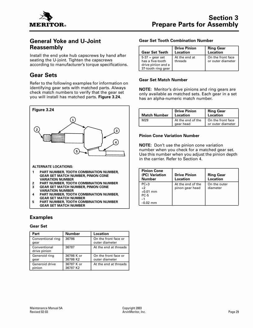
General Yoke and U-Joint Reassembly
Install the end yoke hub capscrews by hand after seating the U-joint. Tighten the capscrews according to manufacturer’s torque specifications.
Gear Sets
Refer to the following examples for information on identifying gear sets with matched parts. Always check match numbers to verify that the gear set you will install has matched parts.
Figure 3.24
.
Examples
Gear Set
Gear Set Tooth Combination Number
Gear Set Match Number
NOTE:
Meritor’s drive pinions and ring gears are only available as matched sets. Each gear in a set has an alpha-numeric match number.
Pinion Cone Variation Number
NOTE:
Don’t use the pinion cone variation number when you check for a matched gear set. Use this number when you adjust the pinion depth in the carrier. Refer to Section 4.
Figure 3.24
ALTERNATE LOCATIONS:
1 PART NUMBER, TOOTH COMBINATION NUMBER,GEAR SET MATCH NUMBER, PINION CONE VARIATION NUMBER
2 PART NUMBER, TOOTH COMBINATION NUMBER3 GEAR SET MATCH NUMBER, PINION CONE
VARIATION NUMBER4 PART NUMBER, TOOTH COMBINATION NUMBER,
GEAR SET MATCH NUMBER5 PART NUMBER, TOOTH COMBINATION NUMBER
GEAR SET MATCH NUMBER
Part Number Location
Conventional ring gear
36786 On the front face or outer diameter
Conventional drive pinion
36787 At the end at threads
Generoid ring gear
36786 K or 36786 K2
On the front face or outer diameter
Generoid drive pinion
36787 K or 36787 K2
At the end at threads
4
5
1
2 3
Gear Set TeethDrive Pinion Location
Ring Gear Location
5-37 = gear set has a five-tooth drive pinion and a 37-tooth ring gear
At the end at threads
On the front face or outer diameter
Match NumberDrive Pinion Location
Ring Gear Location
M29 At the end of the gear head
On the front face or outer diameter
Pinion Cone (PC) Variation Number
Drive Pinion Location
Ring Gear Location
PC+3+2+0.01 mmPC-5–1–0.02 mm
At the end of the pinon gear head
On the outer diameter

Section 4Assembly
Copyright 2003 Maintenance Manual 5APage 30 ArvinMeritor, Inc. Revised 02-03
Section 4Assembly
WARNING
To prevent serious eye injury, always wear safe eye protection when you perform vehicle maintenance or service.
Use a brass or leather mallet for assembly and disassembly procedures. Do not hit steel parts with a steel hammer. Pieces of a part can break off and cause serious personal injury.
Observe all warnings and cautions provided by the press manufacturer to avoid damage to components and serious personal injury.
Assembly
Drive Pinion, Bearings and Bearing Cage
1. Place the bearing cage in a press.
Figure 4.1
.
2. Support the bearing cage with metal or wood blocks.
3. Press the bearing cup into the bore of bearing cage until cup is flat against bottom of bore. Use a sleeve of the correct size to install bearing cup.
Figure 4.1
.
NOTE:
Use the same procedure for both bearing cups.
4. Place the drive pinion in a press with the gear head or teeth toward the bottom.
Figure 4.2
.
5. Press the inner bearing cone on the shaft of the drive pinion until the cone is flat against the gear head. Use a sleeve of the correct size against the bearing inner race.
NOTE:
Spigot bearings are usually fastened to the drive pinion with a snap ring. Some are fastened with a peening tool, and some are a two-piece bearing assembly with the inner race pressed on the nose of the pinion and the outer race pressed into its bore in the carrier.
6. Install the spigot bearing using one of the following three procedures.
Installation
One-Piece Spigot Bearing on the Drive Pinion with Snap Ring
NOTE:
The following procedure applies to all axles except:
O
Some 160 Series single axles may use snap rings.
O
Some 160 and 180 Series rear-rear tandem axles may use snap rings.
1. Place the drive pinion in a press with the gear head or the teeth toward the top.
Figure 4.3
.
2. Press the spigot bearing on the end of drive pinion. The bearing must be flat against the gear head. Use a sleeve of the correct size against the bearing inner race.
Figure 4.3
.
3. Use snap ring pliers to install the snap ring, if equipped, into the groove in the end of the drive pinion.
Figure 4.4
.
Figure 4.1
1 PRESS2 SLEEVE3 BEARING CUP
4 CAGE5 SUPPORTS
4
5
1 2
3
Figure 4.2
1 SLEEVE 2 INNER BEARING CONE
1
2

Section 4Assembly
Maintenance Manual 5A Copyright 2003Revised 02-03 ArvinMeritor, Inc. Page 31
One-Piece Spigot Bearing on the Drive Pinion Without Snap Ring
NOTE:
The following procedure applies to some 180 Series rear-rear tandem axles with existing snap ring components.
For ordering information about the staking tool, refer to the Service Notes page on the front inside cover of this manual.
Figure 4.5
.
1. Place the drive pinion and the tube of the staking tool in a press with the spigot bearing toward the top.
Figure 4.6
.
2. When using a staking tool and press, apply 6,614 lb (3 000 kg) force on a 0.375-inch (10 mm) ball. Calculate the force required on the tool as follows.
6,614 lb (3 000 kg) x amount of balls in tool = pounds or kilograms
Example
6,614 lb (3 000 kg) x 3 balls = 19,842 pounds (9 000 kg)
3. Place the punch of the staking tool over the end of the pinion and spigot bearing. Apply the required amount of force on the punch.
Figure 4.6
.
Figure 4.3
1 PRESS2 SLEEVE3 SPIGOT BEARING
Figure 4.4
1 SNAP RING2 SPIGOT BEARING
12
3
1
2
Figure 4.5
1 PUNCH2 TUBE
Figure 4.6
1 PRESS2 Install and center the punch on the end of pinion.3 SPIGOT BEARING4 Place the shaft of pinion into tube.
1
2
4
1
2
3

Section 4Assembly
Copyright 2003 Maintenance Manual 5APage 32 ArvinMeritor, Inc. Revised 02-03
CAUTION
Do not align new points with the grooves in the end of the drive pinion or in old points. If the new staked points are placed in the wrong areas, the spigot bearing will not be held correctly on the pinion shaft.
NOTE:
If a three-ball stake tool is used, rotate the tool 180 degrees.
4. Stake the end of the drive pinion at a minimum of five points.
Figure 4.7
. Rotate the punch as many times as required for a minimum of five points. Repeat Step 3 for each point.
Two-Piece Spigot Bearing on the Drive Pinion
NOTE:
This procedure applies to some 160 Series single rear axles and rear-rear tandem axles. These axles may also use a one-piece spigot bearing with a snap ring retainer.
NOTE:
The inner race of two-piece spigot bearings must be staked in place on RS and RR-160 series rear axles. Before you stake the pinion, you must heat the pinion stem to soften it.
NOTE:
SPX Kent-Moore kit number J-39039 includes the staking tool, temperature indicating liquid, heat shield and plastigage needed for this procedure. To obtain this kit, refer to the Service Notes page on the front inside cover of this manual.
1. Apply two stripes of temperature indicating liquid on the pinion stem from the top to the bottom.
Figure 4.8
. Apply a green stripe to indicate 400°F (205°C) and a blue stripe to indicate 500°F (260°C).
CAUTION
You must use the heat shield when you heat the pinion stem. Do not heat the pinion stem without the heat shield in place. Damage to components can result.
2. Place the heat shield over the pinion stem so that you can see the temperature indicating liquid through the hole in the shield.
Figure 4.9
.
Figure 4.7
1 STAKING POINTS
1
Figure 4.8
1 TEMPERATURE INDICATING LIQUID APPLICATION
Figure 4.9
1
1003040a

Section 4Assembly
Maintenance Manual 5A Copyright 2003Revised 02-03 ArvinMeritor, Inc. Page 33
WARNING
Read the manufacturer’s instructions before using a torch. Always wear safe clothing, gloves and eye protection when working with a torch for heating parts to prevent serious personal injury during assembly.
3. Put on safe clothing, gloves and eye protection.
CAUTION
Do not overheat the pinion stem or you will weaken the metal. Damage to components can result.
NOTE:
Correct heating will take approximately 25-35 seconds, depending on how hot the torch is.
4. Light and adjust the torch until the white part of the flame is approximately 0.25-inch (6 mm) long. Keep the white part of the flame approximately 0.125-inch (3 mm) from the top of the stem.
Figure 4.10
. Move the flame around the outer diameter of the top of the pinion stem. The green temperature indicating liquid will turn black before the blue liquid does. Heat the stem until the blue liquid turns black at a point in the middle of the window.
5. Remove the flame and the heat shieldfrom the pinion. Let the pinion air cool for 10 minutes. Use a razor blade to remove the temperature indicating liquid.
CAUTION
Do not press or directly strike the new inner race. Damage to the bearing will result.
6. Use a press, if available, or a brass hammer to install the new inner race. Use the old inner race as a sleeve. The face is completely seated when you cannot fit a 0.002-inch (0.0508 mm) feeler gauge between the race and the pinion shoulder.
NOTE:
To hold the races in place, use a staking tool, not the old race, to start the new race on the stem. The old race can be used to completely seat the new race.
7. Place the staking tool over the bearing race. Cut a 1-inch (25 mm) piece from the green plastigage strip and place in between the punch and the staking tool. You do not need to use the plastigage for every stake. Use the plastigage until you are sure you are hitting the punch with the correct amount of force.
Figure 4.11
.
8. Strike the punch with a 2-3 pound (0.9-1.4 kg) brass hammer to upset the end of the pinion stem. Remove the strip and measure its thickness against the gauge on the strip’s wrapper. The strip must not be less than 0.003-inch (0.0762 mm) thick. This thickness indicates that you are using enough force when you hit the punch. If the strip is too thin, then you must hit the punch harder so the stake will hold the race in place. Rotate the tool and repeat this procedure until there are six evenly spaced stake marks around the stem.
Figure 4.11
.
9. With a press or a soft mallet and sleeve, install the outer race and roller assembly into its bore in the carrier. Use a sleeve that is the same size as the outer race. Press the bearing until it is squarely against the shoulder in the bottom of its bore.
Figure 4.10
1 TORCH2 WHITE PART OF FLAME3 0.25-INCH (6 MM)
4 0.125-INCH (3 MM)5 PINION6 HEAT SHIELD
6
4
5
1
2 3

Section 4Assembly
Copyright 2003 Maintenance Manual 5APage 34 ArvinMeritor, Inc. Revised 02-03
Drive Pinion
1. Apply axle lubricant to the bearing cups and to the bearing cones in the cage.
2. Install the drive pinion into the bearing cage.
3. Install the bearing spacer or spacers onto the pinion shaft against the inner bearing cone.
Figure 4.12
. The spacer or spacers control the preload adjustment of the drive pinion bearings.
4. Install the outer bearing cone onto the pinion shaft against the spacer. Do not install the pinion seal in the bearing cage.
Figure 4.12
.
Adjustment
Pinion Bearing Preload
Press Method
If a press is not available, or the press does not have a pressure gauge, use the yoke or flange method to adjust pinion bearing preload. Refer to Yoke or Flange Method.
NOTE:
Do not read starting torque. Read only the torque value after the cage starts to rotate. Starting torque will give an incorrect reading.
1. Place the drive pinion and cage assembly in a press, gear head or teeth toward the bottom.
2. Install a sleeve of the correct size against the inner race of the outer bearing.
Figure 4.13
.
Figure 4.11
1 PUNCH2 PLASTIGAGE3 STAKING TOOL
4 BEARING INNER RACE5 STAKES
4
5
1
2
3
Figure 4.12
1 OUTER BEARING CONE2 BEARING SPACER3 BEARING CAGE4 INNER BEARING CONE5 DRIVE PINION
45
1
2
3

Section 4Assembly
Maintenance Manual 5A Copyright 2003Revised 02-03 ArvinMeritor, Inc. Page 35
3. Apply and hold the correct amount of pressure to the pinion bearings. Refer to
Table B
. As pressure is applied, rotate the bearing cage several times so that the bearings make normal contact.
4. While pressure is held against the assembly, wind a cord around the bearing cage several times.
5. Attach a spring scale to the end of the cord.
6. Pull the cord on a horizontal line. As the bearing cage rotates, read the value indicated on the scale. Record the reading.
Figure 4.13
.
7. Measure the diameter of the bearing cage where the cord was wound. Measure in inches or centimeters.
Figure 4.14
.
8. Divide the dimension in half to get the radius. Record the radius dimension.
Table B
9. Use the following procedure to calculate the bearing preload or torque.
O
Pounds Pulled x Radius (inches) = lb-in Preload
— Preload x 0.113 = N•m Preload
O
Kilograms Pulled x Radius (cm) = kg-cm lb-in Preload
— Preload x 0.098 = N•m Preload
or
Examples
O
Reading from spring scale = 7.5 pounds (3.4 kg)
O
Diameter of bearing cage = 6.62-inches (16.8 cm)
O
Radius of bearing cage = 3.31-inches (8.4 cm)7.5 lb x 3.31 in = 24.8 in-lb PreloadPreload x 0.113 = 2.8 N•m Preload
or3.4 kg x 8.4 cm = 28.6 kg-cm Preload Preload x 0.098 = 2.8 N•m Preload
Figure 4.13
1 PRESS2 SLEEVE
Figure 4.14
1 Measure diameter of cage.
1
2
11003045b
Thread Size of Pinion Shaft
Press Pressure Needed on Bearings for Correct Preload
Torque Value Needed on Pinion Nut for Correct Bearing Preload
pounds/tons
(kg/metric tons) lb-ft (N•m)
7/8"-20 22,000/1 (9979/10) 200-275 (271-373)
1"-20 30,000/15 (13 608/13.6) 300-400 (407-542)
1-1/4"-12 54,000/27 (24 494/24.5) 700-900 (949-1220)
1-1/4"-18 54,000/27 (24 494/24.5) 700-900 (949-1220)
1-1/2"-12 54,000/27 (24 494/24.5) 800-1100 (1085-1491)
1-1/2"-18 54,000/27 (24 494/24.5) 800-1100 (1085-1491)
1-3/4"-12 50,000/25 (22 680/22.7) 900-1200 (1220-1627)
2"-12 50,000/25 (22 680/22.7) 1200-1500 (1627-2034)

Section 4Assembly
Copyright 2003 Maintenance Manual 5APage 36 ArvinMeritor, Inc. Revised 02-03
10. If the preload or torque of pinion bearings is not within 5-45 lb-in (0.56-5.08 N•m) for new pinion bearings or 10-30 lb-in(1.13-3.39 N•m) for used pinion bearings in good condition, adjust the spacer and repeat Steps 1 through 9.
O
To increase preload:
Install a thinner bearing spacer.
O
To decrease preload:
Install a thicker bearing spacer.
11. Check the bearing preload with the drive pinion and cage assembly installed in the carrier. Follow the procedures to adjust pinion bearing preload, yoke or flange method.
Yoke or Flange Method
CAUTION
Do not install tight-fitting yokes or flanges on shafts using a hammer or mallet. A hammer or mallet will damage the yoke or flange.
1. Use a press to install the input yoke or flange, nut and washer, if equipped, onto the drive pinion. The yoke or flange must be seated against the outer bearing.
Figure 4.15
.
2. Install the drive pinion and cage assembly into the carrier. Do not install shims under the bearing cage.
Figure 4.16
.
3. Install the bearing cage-to-carrier capscrews. Washers are not required at this time. Hand-tighten the capscrews.
4. Fasten a yoke or flange bar to the input yoke or flange. The bar will hold the drive pinion in position when the nut is tightened.
Figure 4.17
.
5. Tighten the drive pinion nut to the correct torque value.
Figure 4.17
. Refer to
Table B
.
6. Remove the yoke or flange bar.
7. Attach a torque wrench on the drive pinion nut. Rotate the drive pinion and read the value indicated on torque wrench.
Figure 4.18
.
Figure 4.15
1 PRESS2 INPUT FLANGE SHOWN
T
1
2
Figure 4.16
Figure 4.17
1 FLANGE BAR SHOWN
1003355b
1

Section 4Assembly
Maintenance Manual 5A Copyright 2003Revised 02-03 ArvinMeritor, Inc. Page 37
8. If the pinion bearing preload or torque is not within 5-45 lb-in (0.56-5.08 N•m) for new pinion bearings or 10-30 lb-in (1.13-3.39 N•m) for used pinion bearings in good condition, remove the pinion and cage assembly from the carrier. Adjust the spacer and repeat Steps 1 through 7.
O
To increase preload:
Install a thinner bearing spacer.
O
To decrease preload:
Install a thicker bearing spacer.
9. After adjusting pinion bearing preload, remove the drive pinion and bearing cage from the carrier. Refer to Section 2.
10. Install a new triple-lip seal.
CAUTION
The seal lips must be clean. Dirt and particles may cause a leak between the yoke and the seal.
A. Apply the same lubricant used in the axle housing to the outer surface of the seal and the seal bore in the bearing cage.
Figure 4.19
.
B. Place the drive pinion and cage assembly in a press with the seal bore toward the top.
C. Press the seal into the bearing cage. The seal flange must be flat against the top of the bearing cage. Use a sleeve or seal driver of the correct size that fits against the metal seal flange. The diameter of the sleeve or driver must be larger than the flange diameter.
Figure 4.20
.
O
If a press is not available:
Use a mallet and the sleeve or driver to install the seal.
Figure 4.21
.
D. After the triple-lip seal is installed, a gap of approximately 0.015-0.030-inch (0.38-0.76 mm) between the flange and bearing cage is normal.
Figure 4.22
.
E. Check the gap with a feeler gauge at several points around the seal. The gap must be within 0.015-0.030-inch (0.38-0.76 mm). The difference between the largest and smallest gap measurement must not exceed 0.010-inch (0.0254 mm).
Figure 4.18
1 Read torque value.
1
T
Figure 4.19
1 Apply grease.2 TRIPLE-LIP, MAIN SEAL3 Apply lubricant to seal bore.
4 BEARING CAGE5 DRIVE PINION
4
5
2
31

Section 4Assembly
Copyright 2003 Maintenance Manual 5APage 38 ArvinMeritor, Inc. Revised 02-03
Shim Pack Thickness for a New Drive Pinion
NOTE: Use this procedure if you’ll install a new drive pinion and ring gear set, or if you have to adjust the depth of the drive pinion. Figure 4.23.
1. Use a micrometer to measure the thickness of the shim pack that was removed from under the pinion cage. Record the measurement. Figure 4.24.
2. Find the pinion cone (PC) variation number on the drive pinion you’ll replace. Figure 4.25. Record the number. The pinion cone number can be one of the following values.
O PC +3, PC –3, +3 or –3 = 0.003-inch
O PC +.03, PC 0.03 mm, +0.03 mm or–0.03 = 0.03 mm
Figure 4.20
1 PRESS2 SLEEVE3 SUPPORTS4 SLEEVE
5 SEAL6 BEARING CAGE7 DRIVE PINION
Figure 4.21
1 SEAL DRIVER
Figure 4.22
1 0.015-0.030” (0.38-0.76 MM)
SHOWN WITHOUT BEARINGS AND PINION
7
4
5
1
2
3
6
1
1
Figure 4.23
1 SHIM PACK CONTROLS DEPTH OF PINION
2 BEARING CAGE3 CARRIER
Figure 4.24
3
21

Section 4Assembly
Maintenance Manual 5A Copyright 2003Revised 02-03 ArvinMeritor, Inc. Page 39
3. If you can’t find the PC number or it’s unreadable, install a new shim pack of the same thickness that you measured in Step 1.
4. If the old pinion cone number is a plus (+) number, subtract the number from the old shim pack thickness that was measured in Step 2.
5. If the old pinion cone number is a minus (–) number, add the number to the old shim pack thickness that was measured in Step 2.
6. Find the pinion cone (PC) variation number on the new drive pinion that will be installed. Record the number.
7. If the new pinion cone number is a plus (+) number, add the number to the standard shim pack thickness that was calculated in Step 4 or Step 5. Use new shims to make a shim pack to the correct thickness. Refer to Table C.
8. If the new pinion cone number is a minus (–) number, subtract the number from the standard shim pack thickness that was calculated in Step 4 or Step 5. Use new shims to make a shim pack to the correct thickness. Refer to Table C.
Table C
Installation
Drive Pinion, Bearing Cage and Shim Pack into the Carrier
NOTE: If a new drive pinion and ring gear set is installed, or if the depth of the drive pinion has to be adjusted, calculate the thickness of the shim pack. Refer to the procedure Shim Pack Thickness for a New Drive Pinion.
1. Select the correct shim pack and install it between the bearing cage and carrier. Figure 4.26.
Figure 4.25
1 PINION CONE VARIATION NUMBER
1
Examples Inches mm
1. Old Shim Pack Thickness. Old PC Number, PC +2 inches (+0.05 mm)
Standard Shim Pack Thickness. New PC Number, PC +5 inches (+0.13 mm)
New Shim Pack Thickness
0.030 – 0.002 = 0.028 + 0.005= 0.033
0.760 – 0.050 = 0.710 + 0.130 = 0.840
2. Old Shim Pack ThicknessOld PC Number, PC –2 inches (–0.05 mm)
Standard Shim Pack Thickness. New PC Number, PC +5 inches (+0.13 mm)
New Shim Pack Thickness
0.030 + 0.002 = 0.032 + 0.005 = 0.037
0.760 + 0.050 = 0.810 + 0.130 = 0.940
3. Old Shim Pack ThicknessOld PC Number, PC +2 inches (+0.05 mm)
Standard Shim Pack Thickness. New PC Number, PC –5 inches (–0.13 mm)
New Shim Pack Thickness
0.030 – 0.002 = 0.028 – 0.005 = 0.023
0.760 – 0.050 = 0.710 – 0.130 = 0.580
4. Old Shim Pack ThicknessOld PC Number, PC –2 inches (–0.05 mm)
Standard Shim Pack Thickness. New PC Number, PC –5 inches (–0.13 mm)
New Shim Pack Thickness
0.030 + 0.002 = 0.032– 0.005 = 0.027
0.760 + 0.050= 0.810 – 0.130 = 0.680

Section 4Assembly
Copyright 2003 Maintenance Manual 5APage 40 ArvinMeritor, Inc. Revised 02-03
2. Apply Loctite® 518 Gasket Eliminator to the carrier face.
3. Align the oil slots in the shims with oil slots in the bearing cage and carrier. Use guide studs to help align the shims. Figure 4.26.
4. Apply Loctite® 518 Gasket Eliminator to the top of the shim pack.
5. Install the drive pinion and bearing cage into the carrier. If necessary, use a rubber, plastic or leather mallet to hit the assembly into position. Figure 4.27.
6. Install the bearing cage-to-carrier capscrews and washers. Tighten the capscrews to the correct torque value. Figure 4.28. Refer to Section 7.
Tight Fit Yokes and POSE™ Seal
CAUTION
Do not install tight fit yokes on shafts using a hammer or mallet. Using a hammer or mallet can damage the yoke.
The seal lips must be clean. Dirt and particles may cause a leak between the yoke and the POSE™ seal.
NOTE: Do not install POSE™ seal all the way against the yoke shoulder. This seal is designed to position itself as yoke is installed.
1. Apply axle lubricant on the yoke seal.
2. Check all surfaces of the yoke hub for damage.
3. If the carrier uses a POSE™ seal element, install a new POSE™ seal.
A. Lightly lubricate the yoke journal with the same lubricant used in the axle housing.
B. Partially install the POSE™ seal onto the yoke 0.25-0.5-inch (6-13 mm). Figure 4.29.
C. Before installing the yoke onto the drive pinion, lubricate the yoke with the same lubricant used in the axle housing.
Figure 4.26
1 GUIDE STUDS2 CARRIER
Figure 4.27
1 DRIVE PINION AND BEARING CAGE2 SHIMS3 CARRIER
2
1
2
1
3
Figure 4.28
1001059a

Section 4Assembly
Maintenance Manual 5A Copyright 2003Revised 02-03 ArvinMeritor, Inc. Page 41
4. Slide the yoke over the input shaft pinion. Align the yoke splines with the shaft splines.
CAUTION
Do not use a hammer or mallet to install the yoke to the input pinion shaft. Using a hammer or mallet can damage the yoke or flange.
5. Install the input yoke flange onto the drive pinion shaft. The yoke or flange must be fully seated against the outer differential bearing before the nut is tightened to specifications.
6. Install the drive pinion nut and washer on the input pinion shaft and against the yoke collar. Tighten the nut against yoke collar to torque specifications. Figure 4.30. Refer to Section 7.
Any Type Yoke with a Unitized Pinion Seal (UPS)
NOTE: Once the yoke is partially or fully installed and then removed for any reason, the unitized pinion seal will be damaged and unusable. If the yoke and unitized pinion seal are removed after partial or full installation, remove and discard the original unitized pinion seal and replace it with another new unitized pinion seal.
If the inner sleeve of the seal is removed, the seal is not usable. A new seal is required. This will occur if a yoke is installed into the seal and then removed.
1. Remove the replacement unitized seal from the package. Figure 4.31.
2. Select the correct seal driver from Table D. Each seal driver is designed to correctly install a specific diameter seal. To determine the yoke seal diameter, measure the yoke journal. Refer to Table D.
3. Position the seal on the driver.
Figure 4.29
1 Lubricate triple-lip or main seal.2 INPUT SHAFT, PINION3 POSE™ SEAL, 0.25-0.50” (6-13 MM) ONTO HUB4 Check yoke hub.
Figure 4.30
1 Use flange or yoke bar.
4
1
2
3
1
Figure 4.31
UNITIZED SEAL

Section 4Assembly
Copyright 2003 Maintenance Manual 5APage 42 ArvinMeritor, Inc. Revised 02-03
Table D: Unitized Pinion Seals and Seal Drivers
CAUTION
Use a rubber mallet to install the seal. Do not use a steel, brass or plastic hammer. Damage to the seal and driver tool can result.
4. Use a rubber mallet to drive the seal into or against the bearing cage. The seal must fully seat into or against the bearing cage. Figure 4.32.
5. Use a 0.010-inch (0.25 mm) shim to check for clearance between the entire seal flange circumference and the bearing cage.
O If the 0.010-inch (0.25 mm) shim slides between the seal flange and bearing cage: Correctly position the seal driver and drive the seal into the bore until the 0.010-inch (0.25 mm) shim cannot slide between the seal flange and bearing cage at any point around the seal flange. Figure 4.33.
Single Models Tandem ModelsMeritor Unitized Pinion Seal Seal Installation Location
Meritor Seal Driver
Yoke Seal Diameter Inches
MX-21-160
MX-23-160R
RF-16-145
RF-21-160
RF-22-166
RF-23-185
RS-17-145
RS-19-145
RS-21-145
RS-21-160
RS-23-160 /A
RS-23-161 /A
RS-25-160 /A
RS-23-186
RS-26-185
RS-30-185
RT-34-144 /P
RT-34-145 /P
RT-40-145 /A /P
RT-40-149 /A /P
RT-44-145 /P
RT-40-160 /A /P
RT-40-169 /A /P
RT-46-160 /A /P
RT-46-169 /A /P
RT-46-164EH /P
RT-46-16HEH /P
RT-50-160 /P
RT-52-185*
RT-58-185*
A-1205-R-2592 Tandem Forward Input — 145 models from 11/93 to present
R4422402 3.250
3.255
A-1205-P-2590 Tandem Forward Output — Tandem Forward Input 145 models before 11/93 with seal A-1205-F-2424
R4422401 3.000
3.005
A-1205-N-2588 Tandem and Single Rear Input — 145 models
R4422401 3.000
3.005
A-1205-Q-2591 Tandem and Single Rear Input — 160/164/185 models
R4422402 3.250
3.255
To obtain Meritor seal driver KIT 4454, refer to the Service Notes page on the front inside cover of this manual.
* Forward and rear input only.
Figure 4.32
1 RUBBER MALLET2 REFERENCE MARK3 SEAL DRIVER R4422401
The seal mustbe fully seatedin or againstthe bearing cage.
2
3
1
Figure 4.33
MEASURING SEAL GAP
1 0.010" (0.25 MM)
1

Section 4Assembly
Maintenance Manual 5A Copyright 2003Revised 02-03 ArvinMeritor, Inc. Page 43
Clean, Inspect and Install the Yoke After Installing a Unitized Pinion Seal
WARNING
Solvent cleaners can be flammable, poisonous and cause burns. Examples of solvent cleaners are carbon tetrachloride, and emulsion-type and petroleum-base cleaners. Read the manufacturer’s instructions before using a solvent cleaner, then carefully follow the instructions. Also follow the procedures below.
O Wear safe eye protection.
O Wear clothing that protects your skin.
O Work in a well-ventilated area.
O Do not use gasoline, or solvents that contain gasoline. Gasoline can explode.
O You must use hot solution tanks or alkaline solutions correctly. Read the manufacturer’s instructions before using hot solution tanks and alkaline solutions. Then carefully follow the instructions.
1. Use a clean shop towel and a safe cleaning solvent to clean the ground and polished surface of the yoke journal. Do not use gasoline, abrasive cleaners, towels, or scrubbers to clean the yoke. Do not attempt to polish the yoke.
NOTE: The unitized seal features a rubber inner sleeve that is designed to seal and rotate with the yoke. This feature allows you to reuse a yoke with minor grooves.
2. Inspect the yoke seal surface for grooves.
O If you find grooves on the yoke: Use calipers to measure the groove diameters. If any groove diameter measures less than the dimensions shown in Figure 4.34, replace the yoke.
CAUTION
Do not install a POSE™ seal after you install a unitized pinion seal. The use of a POSE™ seal will prevent correct seating of the unitized pinion seal on the yoke and can result in lubricant leakage at the seal. POSE™ seal installation is recommended only for triple lip and other previous design seals. Damage to components can result.
Do not use thin metal wear sleeves to refresh the yoke surface. Wear sleeves pressed onto the yoke can prevent correct seating of the pinion seal, damage the pinion seal assembly and can cause the seal to leak. Damage to components can result.
3. Before you install the yoke, lightly lubricate or coat the yoke seal journal with axle oil.
4. Align the yoke splines with the shaft splines. Slide the yoke over the shaft spline.
CAUTION
Do not use a hammer or mallet to install the yoke to the input pinion shaft. Using a hammer or mallet can damage the yoke or flange.
5. Install the input yoke flange onto the drive pinion shaft. The yoke or flange must be fully seated against the outer differential bearing before the nut is torqued to specifications.
6. Install the drive pinion nut, and washer if required, on the input pinion shaft and against the yoke collar. Tighten the nut against yoke collar to torque specifications. Figure 4.35. Refer to Section 7.
Figure 4.34
1 MINIMUM GROOVE DEPTH — DIAMETER2 YOKE SEAL DIAMETER
Yoke SealDiameter
3.000/3.005"3.250/3.255"
Minimum Yoke Diameter at Groove (Inches)
2.990"3.240"
A B

Section 4Assembly
Copyright 2003 Maintenance Manual 5APage 44 ArvinMeritor, Inc. Revised 02-03
Assembly
Main Differential and Ring Gear Assembly
CAUTION
Heat the ring gear before seating it onto the differential case. Do not press a cold ring gear on the flange case half. A cold ring gear will damage the case half because of the tight fit.
1. Heat the ring gear in a tank of water to a temperature of 160°F-180°F (71°C-82°C) for 10 to 15 minutes.
WARNING
Wear safe clothing and gloves when working with the hot ring gear to prevent serious personal injury.
2. Use a lifting tool to safely lift the ring gear from the tank of water.
3. Install the ring gear on the flange case half immediately after the gear is heated.
O If the ring gear does not fit easily on the case half: Heat the gear again.
4. Align the ring gear and the flange case half fastener holes. Rotate the ring gear as necessary.
NOTE: If rivets were used to hold the ring gear to the flange case half, replace them with bolts, nuts and washers.
5. Install the bolts, nuts and washers that hold the ring gear to the flange case half. Install the bolts from the gear side of the assembly. The bolt heads must be against the ring gear. Figure 4.36.
6. Tighten the bolts and nuts to the correct torque value. Refer to Section 7.
7. Use a 0.003-inch (0.08 mm) feeler gauge to check for gaps between the back surface of the ring gear and the case flange. Check for gaps at four points around the assembly. Figure 4.37.
O If the gaps exceed specifications: Check the flange case half and ring gear for the problem that causes the gap. Repair or replace parts. Assemble the ring gear on the flange case half. Repeat the procedure in Tight Fit Yokes and POSE™ Seal.
Figure 4.35
1 Use flange or yoke bar.
1 Figure 4.36
1 FLANGE CASE HALF2 RING GEAR3 BOLT HEAD AGAINST GEAR
1
2
3

Section 4Assembly
Maintenance Manual 5A Copyright 2003Revised 02-03 ArvinMeritor, Inc. Page 45
8. Use a press and the correct size sleeve to install the bearing cones on both of the case halves. Figure 4.38.
9. Apply axle lubricant on the inside surfaces of both case halves, spider or cross, thrust washers, side gears and differential pinions.
10. Place the flange case half on a bench with the ring gear teeth toward the top.
11. Install one thrust washer and side gear into the flange case half. Figure 4.39.
CAUTION
The side gears in some carrier models have hubs of different lengths. Install the correct length side gear into the flange case half. Damage to components can result.
12. Install the spider or cross, differential pinions and thrust washers into the flange case half. Figure 4.40.
Figure 4.37
1 Check for 0.003” (0.08 mm) gap at four locations.
Figure 4.38
1 PRESS2 SLEEVE3 BEARING CONE
4 SUPPORT5 SUPPORT6 CASE HALF
1
6
45
1
2
3
Figure 4.39
1 SIDE GEAR2 THRUST WASHER3 FLANGE CASE HALF
Figure 4.40
1 SPIDER, PINION AND THRUST WASHERS
1
2
3
1

Section 4Assembly
Copyright 2003 Maintenance Manual 5APage 46 ArvinMeritor, Inc. Revised 02-03
13. Install the second side gear and thrust washer over the spider and differential pinions. Figure 4.41.
14. Place the plain half of the differential case over the flange half and gears. Rotate the plain half to align the match marks. Figures 4.41 and 4.42.
15. Install Dri-Loc fasteners into the case halves. Refer to Section 3.
A. Install four capscrews and washers or bolts, nuts and washers, if equipped, into the case halves. The distance between the fasteners must be equal. Tighten the fasteners to the correct torque value in a progressive criss-cross pattern opposite each other. Refer to Section 7. Figure 4.43
B. Install the other fasteners into the case halves. Tighten the fasteners to the correct torque value. Refer to Section 7.
16. Check the differential gears rotating resistance.
Differential Gears Rotating Resistance Check
1. Make an inspection tool using an axle shaft that matches the spline size of the differential side gear. Cut the shaft to approximately 12-inches (304.8 mm). Weld a nut onto the end of the shaft. Figure 4.44.
2. Place the differential and ring gear assembly in a vise. Install soft metal covers over vise jaws to protect the ring gear. Figure 4.45.
3. Install the tool into the differential until the splines of the tool are engaged with one side gear. Figure 4.45.
Figure 4.41
1 THRUST WASHER2 SIDE GEAR3 PLAIN CASE HALF
Figure 4.42
1 PLAIN CASE HALF2 MATCH MARKS
1
2
3
1
2
Figure 4.43
Figure 4.44
1 APPROXIMATELY 12" (304.8 MM)2 SIDE VIEW3 Weld nut to end of shaft.4 END VIEW
2
12
7
395
111
8
410 6
13
14
15
16
1
23
4
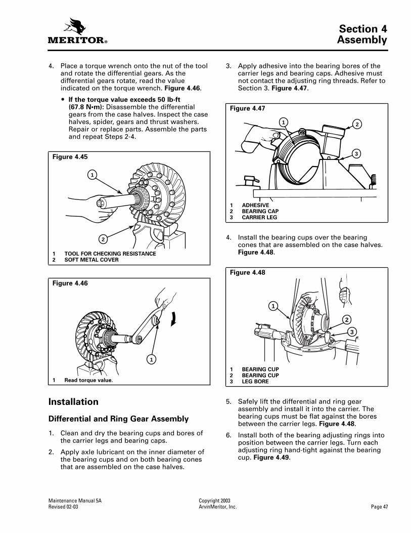
Section 4Assembly
Maintenance Manual 5A Copyright 2003Revised 02-03 ArvinMeritor, Inc. Page 47
4. Place a torque wrench onto the nut of the tool and rotate the differential gears. As the differential gears rotate, read the value indicated on the torque wrench.
Figure 4.46
.
O
If the torque value exceeds 50 lb-ft (67.8 N•m):
Disassemble the differential gears from the case halves. Inspect the case halves, spider, gears and thrust washers. Repair or replace parts. Assemble the parts and repeat Steps 2-4.
Installation
Differential and Ring Gear Assembly
1. Clean and dry the bearing cups and bores of the carrier legs and bearing caps.
2. Apply axle lubricant on the inner diameter of the bearing cups and on both bearing cones that are assembled on the case halves.
3. Apply adhesive into the bearing bores of the carrier legs and bearing caps. Adhesive must not contact the adjusting ring threads. Refer to Section 3.
Figure 4.47
.
4. Install the bearing cups over the bearingcones that are assembled on the case halves.
Figure 4.48
.
5. Safely lift the differential and ring gear assembly and install it into the carrier. The bearing cups must be flat against the bores between the carrier legs.
Figure 4.48
.
6. Install both of the bearing adjusting rings into position between the carrier legs. Turn each adjusting ring hand-tight against the bearing cup.
Figure 4.49
.
Figure 4.45
1 TOOL FOR CHECKING RESISTANCE2 SOFT METAL COVER
Figure 4.46
1 Read torque value.
1
2
1
Figure 4.47
1 ADHESIVE2 BEARING CAP3 CARRIER LEG
Figure 4.48
1 BEARING CUP2 BEARING CUP3 LEG BORE
1 2
3
1
2
3

Section 4Assembly
Copyright 2003 Maintenance Manual 5APage 48 ArvinMeritor, Inc. Revised 02-03
7. Install the bearing caps over the bearings and adjusting rings. Align the match marks you made when you removed the caps. Figure 4.50.
CAUTION
If bearing caps are not installed in correct locations, the bores and threads in caps will not match the carrier. You will have problems assembling the caps on the carrier and damage to parts can occur. Do not force the bearing caps into position.
8. Seat each bearing cap with a light leather, plastic or rubber mallet. The caps must fit easily against the bearings, adjusting rings and carrier. Do not force the bearing capsinto position.
O If bearing caps do not correctly fit into position: Check the alignment of match marks between caps and carrier. Remove the caps and repeat Steps 6-8.
9. Install the capscrews and washers that hold bearing caps to the carrier. Hand-tighten the capscrews four to six turns. Tighten the capscrews to the correct torque value. Refer to Section 7.
NOTE: Do not install the cotter keys, pins or lock plates, if equipped, that hold the bearing adjusting rings in position.
10. Adjust differential bearing preload and hypoid gear backlash. Check the tooth contact patterns.
Adjust Differential Bearing Preload
Method 1
1. Attach a dial indicator onto the carrier mounting flange so that the plunger or pointer is against the ring gear back surface. Figure 4.51.
Figure 4.49
1 ADJUSTING RING2 LEG
Figure 4.50
1 BEARING CAP2 MATCH MARKS
1
2
2
1
Differential Bearing Preload
All Carrier Models
15-35 lb-in (1.7-3.9 N•m)
Expansion between bearing caps
RS-140, RS-145 and RS-160 carrier models
0.002-0.009-inch (0.05-0.229 mm)
RS-120 and all other carrier models
0.006-0.013-inch (0.15-0.33 mm)
Figure 4.51
1 DIAL INDICATOR
1

Section 4Assembly
Maintenance Manual 5A Copyright 2003Revised 02-03 ArvinMeritor, Inc. Page 49
CAUTION
When you turn the adjusting rings, always use a tool that engages two or more opposite notches in the ring. A T-bar wrench can be used for this purpose. If the tool does not correctly fit into the notches, damage to the lugs will occur.
2. Use a T-bar wrench to loosen the bearing adjusting ring that is opposite the ring gear.A small amount of end play will show on the dial indicator. Figure 4.52.
3. Use one of the following methods to move the differential and ring gear to the left and right while you read the dial indicator.
A. Insert two pry bars between the bearing adjusting rings and ends of the differential case. The pry bars must not touch the differential bearings. Figure 4.53.
B. Insert two pry bars between the differential case or ring gear and the carrier at locations other than described in Step A. The pry bars must not touch the differential bearings. Figure 4.54.
4. Tighten the bearing adjusting ring until the dial indicator reads ZERO end play. Move the differential and ring gear to the left and right as needed. If necessary, repeat Step A or B.
5. Tighten each bearing adjusting ring one notch from ZERO.
6. Proceed to check ring gear runout.
Method 2
1. Hand-tighten both adjusting rings against the differential bearings.
2. Use a micrometer to measure distance X or Y between the opposite surfaces of the bearing caps. Figures 4.55 and 4.56. Record the measurement.
Figure 4.52
1 T-BAR WRENCH2 ADJUSTING RING OPPOSITE RING GEAR
1
2
Figure 4.53
1 Bars must not touch bearings.
Figure 4.54
1 Bars must not touch bearings.
1
1

Section 4Assembly
Copyright 2003 Maintenance Manual 5APage 50 ArvinMeritor, Inc. Revised 02-03
3. Tighten each bearing adjusting ring one notch.
4. Measure distance X or Y again. Compare the measurement with the one you obtained in Step 2. The difference between the two dimensions is the amount the bearing caps have expanded.
Example
O Measurements of RS-145 carrier
O Distance X or Y — before tightening adjusting rings =
13.927-inch (353.74 mm).
O Distance X or Y — after tightening adjusting rings =
13.936-inch (353.97 mm)
O 13.936-inch – 13.927-inch = 0.009-inch (0.23 mm) difference.
O If the dimension is within specifications: Continue by checking ring gear runout.
O If the dimension is less than specifications: Repeat Steps 3 and 4 as needed.
Check Ring Gear Runout
1. Attach a dial indicator onto the carrier mounting flange. Figure 4.57.
2. Adjust the dial indicator so that the plunger or pointer is against the back surface of the ring gear. Set the dial indicator to ZERO.
3. Rotate the differential and ring gear. Read the dial indicator. Runout must not exceed 0.008-inch (0.20 mm). Figure 4.57.
O If runout exceeds specifications: Remove the differential and ring gear assembly from the carrier. Refer to Differential and Ring Gear from the Carrier in Section 2 and Steps 4 and 5 below.
O If runout is within specifications: Proceed to Ring Gear Backlash Adjustment.
4. Check the differential parts including the carrier for wear and damage. Repair or replace parts.
5. Install the differential and ring gear into the carrier. Refer to Differential and Ring Gear Assembly in this section. Repeat preload adjustment of differential bearings.
Figure 4.55
Figure 4.56
1 MICROMETER
1
Figure 4.57
1 Rotate ring gear.2 DIAL INDICATOR
1
2

Section 4Assembly
Maintenance Manual 5A Copyright 2003Revised 02-03 ArvinMeritor, Inc. Page 51
Ring Gear Backlash Adjustment
Measure the outer diameter of ring gear for approximate pitch diameter. Figure 4.58.
O If the old gear set is installed: Adjust the backlash to the setting that was measured before the carrier was disassembled.
O If a new gear set is installed: Adjust the backlash to the correct specification for new gear sets.
After checking the tooth contact patterns, the backlash can be adjusted within specification limits, if needed. To change the location of the pattern use the following procedures.
1. Attach a dial indicator onto the mounting flange of the carrier. Figure 4.59.
2. Adjust the dial indicator so that the plungeror pointer is against the tooth surface. Figure 4.59.
3. Adjust the indicator dial to ZERO. Hold the drive pinion in position.
4. After reading the dial indicator, rotate the differential and ring gear a small amount in both directions against the drive pinion teeth.
O If the backlash reading is within specifications: Check the tooth contact patterns.
O If the backlash reading is not within specifications: Adjust backlash as needed.
5. Loosen one bearing adjusting ring one notch then tighten the opposite ring the same amount.
O To increase backlash: Move the ring gear away from the drive pinion. Figure 4.60.
O To decrease backlash: Move the ring gear toward the drive pinion. Figure 4.61.
Ring Gear Pitch Diameter
Range of Backlash Setting
Backlash Setting for New Gear Sets
Less than 17-inches (431.8 mm)
0.008-0.018-inch (0.20-0.46 mm)
0.012-inch(0.30 mm)
Greater than 17-inches(431.8 mm)
0.010-0.020-inch (0.25-0.51 mm)
0.015-inch(0.38 mm)
Figure 4.58
1 Measure outer diameter for approximate pitch diameter.
1
Figure 4.59
Figure 4.60
1 Tighten adjusting ring this side.2 Increase backlash.3 Loosen adjusting ring this side.
2
1
3

Section 4Assembly
Copyright 2003 Maintenance Manual 5APage 52 ArvinMeritor, Inc. Revised 02-03
NOTE: When you adjust backlash, move the ring gear only. Do not move the drive pinion.
6. Repeat Steps 2-5 until the backlash is within specifications.
Check Gear Set Tooth Contact Patterns (Backlash)
Some Meritor carriers have a generoid hypoid gear set. The tooth contact patterns for each type of gear set are different. Check the part numbers to determine what type of gear set is in the carrier. Refer to Figure 4.62 for the location of part numbers.
Examples
Part numbers for generoid gear sets
O 36786-K or 36786-K2 for the ring gear
O 36787-K or 36787-K2 for the drive pinion
In the following procedures, movement of the contact pattern in the length of the tooth is indicated as toward the heel or toe of the ring gear. Figure 4.63.
Always check tooth contact patterns on the drive side of the gear teeth. Figure 4.64.
1. Adjust the backlash of a new gear set to either 0.012-inch (0.305 mm) or 0.015-inch (0.380 mm) depending on the size of the ring gear. Adjust the backlash of an old gear set to the setting that you measured before the carrier was disassembled. Refer to Ring Gear Backlash Adjustment.
Figure 4.61
1 Loosen adjusting ring this side.2 Decrease backlash.3 Tighten adjusting ring this side.
Figure 4.62
1 PART NUMBER2 PART NUMBER3 PART NUMBER OPTION
2
1
3
12
3
Figure 4.63
1 HEEL2 TOE
Figure 4.64
1 DRIVE SIDE, CONVEX
1
2
1
1003091b

Section 4Assembly
Maintenance Manual 5A Copyright 2003Revised 02-03 ArvinMeritor, Inc. Page 53
2. Apply a marking compound onto approximately 12 gear teeth of the ring gear. Rotate the ring gear so that the 12 gear teeth are next to the drive pinion. Figure 4.65.
3. Rotate the ring gear forward and backward so that the 12 gear teeth go past the drive pinion six times to get the contact patterns. Repeat if needed to get a clearer pattern.
4. Look at the contact patterns on the ring gear teeth. Compare the patterns to Figures 4.66, 4.67 and 4.68.
The location of good hand-rolled contact patterns for new conventional and generoid gear sets is toward the toe of the gear tooth and in the center between the top and bottom of the tooth. Figure 4.66.
When the carrier is operated, a good pattern will extend approximately the full length of the gear tooth. The top of the pattern will be near the top of the gear tooth. Figure 4.69.
The location of a good hand-rolled contact pattern for an old gear set must match the wear pattern in the ring gear. The new contact pattern will be smaller in area than the old wear pattern.
A high contact pattern indicates that the drive pinion was not installed deep enough into the carrier. A low contact pattern indicates that the drive pinion was installed too deep in the carrier.
O If the contact patterns require adjustment: Continue by following Step 5 to move the contact patterns between the top and bottom of the gear teeth.
O If the contact patterns are in the center of the gear teeth: Continue by following Step 6.
Figure 4.65
Figure 4.66
GOOD HAND-ROLLED PATTERN, HYPOID GENEROID GEARS
Figure 4.67
HIGH PATTERN, HYPOID GENEROID GEARS
HIGH PATTERN

Section 4Assembly
Copyright 2003 Maintenance Manual 5APage 54 ArvinMeritor, Inc. Revised 02-03
5. Change the thickness of the shim pack under the bearing cage to move the contact patterns between the top and bottom of the gear teeth. Use the following procedure.
A. Remove the drive pinion and bearing cage from the carrier. Refer to Drive Pinion and Bearing Cage from the Carrier in Section 2.
O To correct a high contact pattern: Decrease the thickness of the shim pack under the bearing cage. When decreasing the thickness of the shim pack, the drive pinion will move toward the ring gear. Figure 4.70.
O To correct a low contact pattern: Increase the thickness of shim pack under the bearing cage. When increasing the thickness of the shim pack, the drive pinion will move away from the ring gear. Figure 4.71.
B. Install the drive pinion, bearing cage and shims into the carrier. Refer to Shim Pack Thickness for a New Drive Pinion in this section.
C. Repeat Steps 2-5 until the contact patterns are in the center between the top and bottom of the gear teeth.
Figure 4.68
LOW PATTERN, HYPOID GENEROID GEARS
Figure 4.69
GOOD PATTERN IN OPERATION, GENEROID GEARS
1001094a
1001095
Figure 4.70
1 Decrease shim pack.
Figure 4.71
1 Increase shim pack.
1
1003102b
1
1003101b

Section 4Assembly
Maintenance Manual 5A Copyright 2003Revised 02-03 ArvinMeritor, Inc. Page 55
6. Adjust backlash of the ring gear within the specification range to move the contact patterns to the correct location in the lengthof the gear teeth. Refer to Ring Gear Backlash Adjustment.
A. Decrease backlash to move the contact patterns toward the toe of the ring gear teeth. Figure 4.72.
B. Increase backlash to move the contact patterns toward the heel of the ring gear teeth. Figure 4.73.
C. Repeat Steps 2-4 and Step 6 until the contact patterns are at the correct location in the length of the gear teeth.
CAUTION
If the carrier has cotter keys, lock the adjusting rings only with cotter keys. If the carrier has roll pins, reuse the roll pins or lock the adjusting rings with cotter keys. Do not force a roll pin into a cotter key hole. Damage to components can result.
7. Install the cotter keys, pins, or lock plates, if equipped, that hold the two bearing adjusting rings in position. Use the following procedures.
A. Install cotter keys between the lugs of the adjusting ring and through the boss of the bearing cap. Bend the two ends of the cotter key around the boss. Figure 4.74.
B. Use a drift and hammer to install the pin through the boss of the bearing cap until the pin is between the lugs of the adjusting ring. Figure 4.74.
C. Install the lock plate on the bearing cap so that the tab is between the lugs of the adjusting ring. Install the two capscrews that hold the lock plate to the bearing cap. Tighten the capscrews to correct torque value. Refer to Section 7. Figure 4.74.
Figure 4.72
1 Move pattern toward toe, loosen adjusting ring this side.
2 Decrease backlash.3 Tighten adjusting ring.
Figure 4.73
1 Move pattern toward toe, loosen adjusting ring this side.
2 Decrease backlash.3 Loosen adjusting ring.
1
2
3
1003103b
1
2 3
1003104b
Figure 4.74
1 COTTER KEY2 PIN3 LOCK PLATE4 THREADED HOLES IN CAP WHEN LOCK PLATE IS
USED
1
2
3
4

Section 4Assembly
Copyright 2003 Maintenance Manual 5APage 56 ArvinMeritor, Inc. Revised 02-03
Installation
Adjust the Thrust Screw
1. Rotate the carrier in the repair stand until the back surface of ring gear is toward the top.
2. Install the jam nut on the thrust screw, if equipped, one half the distance between both ends. Figure 4.75.
3. Install the thrust screw. Clearance betweenthe thrust screw and the ring gear must be 0.025-0.045-inch (0.65-1.14 mm).
4. Loosen the thrust screw 1/2 turn, 180 degrees. Figure 4.76.
5. Tighten the jam nut, if equipped, to the correct torque value against the carrier. Refer to Section 7. Figure 4.77.
Figure 4.75
1 THRUST SCREW AND JAM NUT
Figure 4.76
1 Loosen thrust screw 1/2 turn.
1
Figure 4.77
1 Hold thrust screw in position.2 Tighten jam nut to correct torque value.
1
2

Section 4Assembly
Maintenance Manual 5A Copyright 2003Revised 02-03 ArvinMeritor, Inc. Page 57
Differential Carrier into Axle Housing
WARNING
When you apply some silicone gasket materials, a small amount of acid vapor is present. To prevent serious personal injury, ensure that the work area is well-ventilated. Read the manufacturer’s instructions before using a silicone gasket material, then carefully follow the instructions. If a silicone gasket material gets into your eyes, follow the manufacturer’s emergency procedures. Have your eyes checked by a physician as soon as possible.
Solvent cleaners can be flammable, poisonous and cause burns. Examples of solvent cleaners are carbon tetrachloride, and emulsion-type and petroleum-base cleaners. Read the manufacturer’s instructions before using a solvent cleaner, then carefully follow the instructions. Also follow the procedures below.
O Wear safe eye protection.
O Wear clothing that protects your skin.
O Work in a well-ventilated area.
O Do not use gasoline, or solvents that contain gasoline. Gasoline can explode.
O You must use hot solution tanks or alkaline solutions correctly. Read the manufacturer’s instructions before using hot solution tanks and alkaline solutions. Then carefully follow the instructions.
NOTE: To complete the assembly of axles equipped with driver-controlled main differential locks, refer to DCDL Assembly into Carrier in Section 5.
1. Use a cleaning solvent and rags to clean the inside of the axle housing and the carrier mounting surface. Refer to Section 3.
2. Inspect the axle housing for damage. Repair or replace the axle housing. Refer to Section 3.
3. Check for loose studs, if equipped, in the mounting surface of the housing where the carrier fastens. Remove and clean the studs that are loose.
4. Apply liquid adhesive to the threaded holes. Install the studs into axle housing. Refer to Section 3. Tighten the studs to correct torque value. Refer to Section 7.
5. Apply silicone gasket material to the mounting surface of the housing where the carrier fastens. Refer to Section 3. Figure 4.78.
CAUTION
Do not install the carriers using a hammer or mallet. A hammer or mallet will damage the mounting flange of carrier and cause oil leaks.
6. Use a hydraulic roller jack or a lifting tool to install the carrier into the axle housing.
7. Install nuts and washers or capscrews and washers, if equipped, in the four corner locations around the carrier and axle housing. Hand-tighten the fasteners. Figure 4.79.
8. Carefully push the carrier into position. Tighten the four fasteners two or three turns each in a pattern opposite each other. Figure 4.79.
9. Repeat Step 8 until the four fasteners are tightened to the correct torque value. Refer to Section 7.
T
Figure 4.78
1 0.125" (3 MM) DIA. SILICONE GASKET BEAD
Figure 4.79
1

Section 4Assembly
Copyright 2003 Maintenance Manual 5APage 58 ArvinMeritor, Inc. Revised 02-03
10. Install the other fasteners and washers that hold the carrier in the axle housing. Tighten fasteners to the correct torque value. Referto Section 7.
11. Connect the driveline universal joint to the pinion input yoke or flange on the carrier.
12. Install the gaskets and axle shafts into the axle housing and carrier. The gasket and flange of the axle shafts must fit flat against the wheel hub.
Figure 4.80
.
Straight Holes, Nuts and Hardened Washers
1. Clean the mating surfaces of the axle shaft and the wheel hub.
2. If silicone gasket material is used, apply a 0.125-inch (3 mm) diameter bead of the gasket material around the mating surface of the hub and around the edge of each fastener hole.
3. Install the gasket and the axle shaft into the housing. The gasket and the flange of the axle shaft must fit flat against the wheel hub.
Figure 4.80
.
4. Install the Grade 8 nuts and hardened washers on the stud. Lock washers are an acceptable alternative. Tighten the stud nuts to the torque specified in
Table E
.
Table E: Shaft-to-Hub Torque Fastener Chart — Non-Tapered Dowel Applications
Tapered Dowel, Hardened Washer and Hardened Nut
1. Clean the mating surfaces of the axle shaft and the wheel hub.
2. If silicone gasket material is used, apply a 0.125-inch (3 mm) diameter bead of the gasket material around the mating surface of the hub and around the edge of each fastener hole.
3. Install the gasket and the axle shaft into the housing. The gasket and the flange of the axle shaft must fit flat against the wheel hub.
Figure 4.80
.
4. Install solid tapered dowels over each stud and into the flange of the axle shaft. Use a punch or a drift and hammer, if necessary.
5. Install the Grade 8 nuts and hardened washers on the stud. Lock washers are an acceptable alternative. Tighten the stud nuts to the torque specified in
Table F
.
Table F: Shaft-to-Hub Torque Fastener Chart — Tapered Dowel Applications
Figure 4.80
1 TAPERED DOWEL RETENTION
2 STUD NUT3 WASHER4 TAPERED DOWEL5 GASKET6 STUD7 SHAFT HUB AXLE
8 AXLE SHAFT OR FLANGE
9 WASHER10 CAPSCREW11 NON-TAPERED
DOWEL RETENTION
4 56
78910
11
1
2 3
FastenerThread Size
Torque Value — Grade 8 Nuts lb-ft (N•m)
Plain Nut Lock Nut
Stud Nut, Axle Shaft
0.62-18 150-230(244-312)
130-190 (203-258)
0.75-16 310-400(420-542)
270-350 (366-475)
Studs All Install the course thread end of stud into hub and tighten to last thread.
FastenerThread Size
Torque Value — Grade 8 Nuts lb-ft (N•m)
Plain Nut Lock Nut
Stud Nut, Axle Shaft
0.44-20 50-75 (81-102) 40-65 (67-88)
0.50-20 75-115 (115-156) 65-100 (102-136)
0.56-18 110-165 (176-224) 100-145 (149-197)
0.62-18 150-230 (244-312) 130-190 (203-258)
Studs All Install the course thread end of stud into hub and tighten to last thread.

Section 5Driver-Controlled Main Differential Lock
Maintenance Manual 5A Copyright 2003Revised 02-03 ArvinMeritor, Inc. Page 59
Section 5Driver-Controlled Main Differential LockDriver-Controlled Main Differential Lock Assembly
Figure 5.1
1 LOCK NUT — SENSOR SWITCH2 SENSOR SWITCH3 SHIFT FORK4 SHIFT SHAFT SPRING5 SHIFT SHAFT6 SPRING RETAINING PIN7 FLAT WASHER, OR SILASTIC AS REQUIRED8 AIR CYLINDER TUBE9 SCREW-IN DIFFERENTIAL LOCK10 CYLINDER COVER11 CAPSCREW — MANUAL ACTUATION, STORAGE POSITION
12 WASHER, OPERATING POSITION13 PLUG GASKET, OPERATING POSITION14 COVER CAPSCREWS15 WASHERS16 PLUG GASKET, STORAGE POSITION17 COVER PLUG, STORAGE POSITION18 COVER COPPER GASKET19 PISTON O-RING20 PISTON21 SHIFT COLLAR22 SHIFT FORK ROLL PINS
1001107a
12 3
45
6
7
8
9 10
11
12
13
141516
171819
20
21
22
22

Section 5Driver-Controlled Main Differential Lock
Copyright 2003 Maintenance Manual 5APage 60 ArvinMeritor, Inc. Revised 02-03
WARNING
To prevent serious eye injury, always wear safe eye protection when you perform vehicle maintenance or service.
Some Meritor drive axle models have a DCDL or a driver-controlled main differential lock. This differential lock is operated by a carrier-mounted, air-actuated shift unit. When activated, the shift unit moves a sliding collar which is installed on the splines of the axle shaft. When engaged, the collar locks the axle shafts together with a second set of splines on the differential case. When the DCDL is engaged, there is no differential action. Figure 5.1.
NOTE: The Meritor carrier models with driver-controlled differential lock equipment are manufactured in metric dimensions and sizes. When these carriers are serviced, it is important to use the correct metric size tools on the fasteners. Refer to Section 7.
CAUTION
If the vehicle must be towed to a service facility with the drive axle wheels on the ground, remove the axle shafts before the vehicle is towed. Damage to components can result.
1. Remove the axle shafts before the vehicle is towed. Refer to Section 10.
2. Install the axle shafts after the vehicle is towed. Refer to Section 10.
3. If the differential carrier must be removed from the axle housing, use the following procedures.
Removal
Differential Carrier from Axle Housing
WARNING
Park the vehicle on a level surface. Block the wheels to prevent the vehicle from moving. Support the vehicle with safety stands. Do not work under a vehicle supported only by jacks. Jacks can slip and fall over. Serious personal injury and damage to components can result.
Before the differential carrier can be removed or installed, the differential lock must be shifted into and held in the locked or engaged position. The locked position gives enough clearance between the shift collar and the axle housing to permit the removal or installation of the carrier.
NOTE: If the axle shafts were removed for towing with the differential in the unlocked or disengaged position, install the right-hand axle shaft into the housing before removing the differential carrier. Refer to Section 10.
To shift into the locked position, refer to Manual Engaging Method in this section.
Axle Setup for DCDL Disassembly
1. Park the vehicle on a level surface. Block the wheels to prevent the vehicle from moving.
2. Remove the drain plug from the bottom of the housing and drain the lubricant.
WARNING
During DCDL disassembly, when the DCDL is in the locked or engaged position and the vehicle’s wheels are raised from the floor, do not start the engine and engage the transmission. The vehicle can move and cause serious personal injury. Damage to components can result.
3. Use a jack to raise the vehicle so that the wheels to be serviced are off the ground. Place a safety stand under the spring seats to hold the vehicle in the raised position.
4. Disconnect the driveline from the pinion input yoke.
5. Disconnect the vehicle air line from the differential lock actuator assembly.
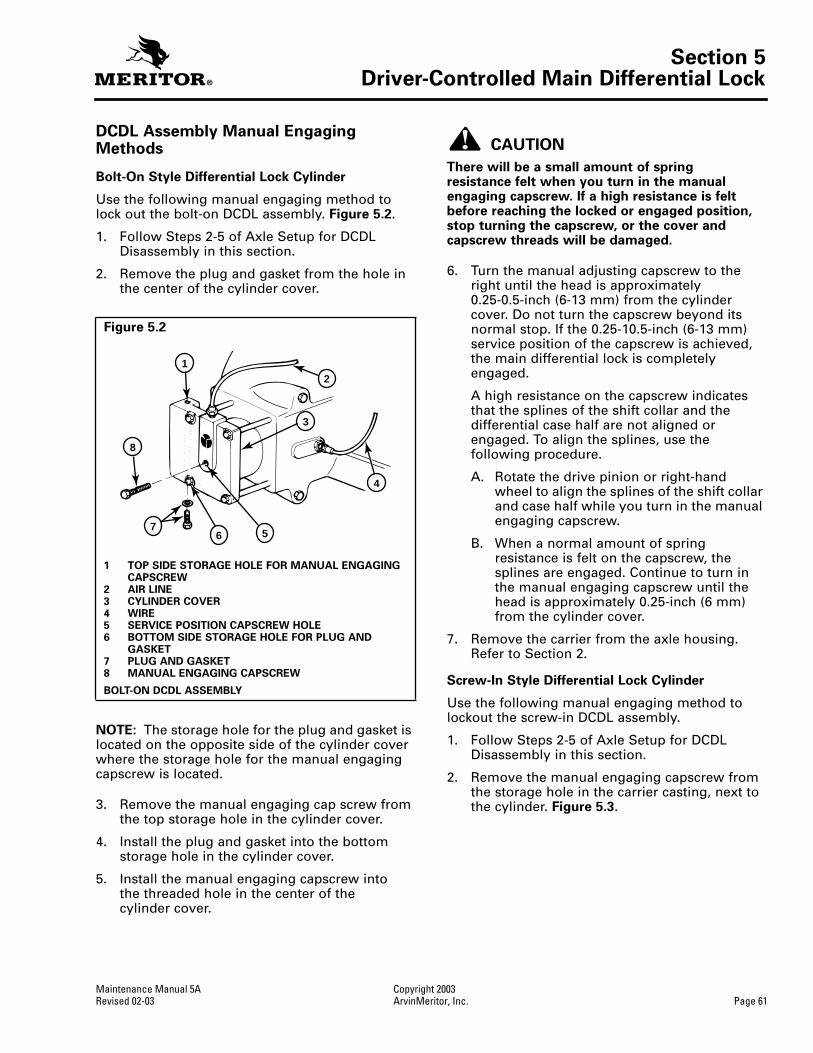
Section 5Driver-Controlled Main Differential Lock
Maintenance Manual 5A Copyright 2003Revised 02-03 ArvinMeritor, Inc. Page 61
DCDL Assembly Manual Engaging Methods
Bolt-On Style Differential Lock Cylinder
Use the following manual engaging method to lock out the bolt-on DCDL assembly. Figure 5.2.
1. Follow Steps 2-5 of Axle Setup for DCDL Disassembly in this section.
2. Remove the plug and gasket from the hole in the center of the cylinder cover.
NOTE: The storage hole for the plug and gasket is located on the opposite side of the cylinder cover where the storage hole for the manual engaging capscrew is located.
3. Remove the manual engaging cap screw from the top storage hole in the cylinder cover.
4. Install the plug and gasket into the bottom storage hole in the cylinder cover.
5. Install the manual engaging capscrew intothe threaded hole in the center of thecylinder cover.
CAUTION
There will be a small amount of spring resistance felt when you turn in the manual engaging capscrew. If a high resistance is felt before reaching the locked or engaged position, stop turning the capscrew, or the cover and capscrew threads will be damaged.
6. Turn the manual adjusting capscrew to the right until the head is approximately 0.25-0.5-inch (6-13 mm) from the cylinder cover. Do not turn the capscrew beyond its normal stop. If the 0.25-10.5-inch (6-13 mm) service position of the capscrew is achieved, the main differential lock is completely engaged.
A high resistance on the capscrew indicates that the splines of the shift collar and the differential case half are not aligned or engaged. To align the splines, use the following procedure.
A. Rotate the drive pinion or right-hand wheel to align the splines of the shift collar and case half while you turn in the manual engaging capscrew.
B. When a normal amount of spring resistance is felt on the capscrew, the splines are engaged. Continue to turn in the manual engaging capscrew until the head is approximately 0.25-inch (6 mm) from the cylinder cover.
7. Remove the carrier from the axle housing. Refer to Section 2.
Screw-In Style Differential Lock Cylinder
Use the following manual engaging method to lockout the screw-in DCDL assembly.
1. Follow Steps 2-5 of Axle Setup for DCDL Disassembly in this section.
2. Remove the manual engaging capscrew from the storage hole in the carrier casting, next to the cylinder. Figure 5.3.
Figure 5.2
1 TOP SIDE STORAGE HOLE FOR MANUAL ENGAGING CAPSCREW
2 AIR LINE3 CYLINDER COVER4 WIRE5 SERVICE POSITION CAPSCREW HOLE6 BOTTOM SIDE STORAGE HOLE FOR PLUG AND
GASKET7 PLUG AND GASKET8 MANUAL ENGAGING CAPSCREW
BOLT-ON DCDL ASSEMBLY
12
3
4
567
8

Section 5Driver-Controlled Main Differential Lock
Copyright 2003 Maintenance Manual 5APage 62 ArvinMeritor, Inc. Revised 02-03
3. Remove air line and fitting. Install the manual engaging capscrew into the threaded hole in the center of the cylinder cover.
4. Turn the manual adjusting capscrew to the right until the head is approximately 0.25-inch (6 mm) from the cylinder cover. Do not turn the capscrew beyond its normal stop. The capscrew is now in the service position and the main differential lock is completely engaged.
5. Remove the carrier from the axle housing. Refer to Section 2.
Differential and Gear Assembly
Differential Lock Sliding Collar
1. For carriers with roll pins, tap out the two retainer roll pins, if equipped, until they are level with the inner face of the shift fork. Release the differential lock if it is manually engaged. Figure 5.4.
2. For carriers without roll pins, snap out collar from fork.
3. If required, remove the DCDL assembly at this time.
Bolt-On Style Differential Lock Cylinder
NOTE: On some bolt-on assemblies, a roll pin is installed in the shift shaft and is used as a stop for the shift shaft spring. It is not necessary to remove this roll pin during a normal disassembly.
A. Remove the sensor switch and lock nut.
B. Remove the four capscrews and washers that hold the cylinder cover to carrier. Remove the cylinder cover and copper gasket. Figure 5.5.
C. Remove the shift unit-cylinder and piston. Remove the O-ring from the piston.
D. Remove the shift shaft from the shift fork. The shaft may be secured with liquid adhesive or pre-applied adhesive material. Refer to Section 3.
E. Remove the shift shaft spring and flat washer. Some models use silastic seal instead of the flat washer.
F. Remove the shift fork.
Figure 5.3
1 STORAGE HOLE2 CYLINDER
3 MANUAL ENGAGING CAPSCREW
4 AIR HOSE
THREADED SHIFT ASSEMBLY
1
3
42
Figure 5.4
1 SHIFT COLLAR2 SHIFT FORK
1
2

Section 5Driver-Controlled Main Differential Lock
Maintenance Manual 5A Copyright 2003Revised 02-03 ArvinMeritor, Inc. Page 63
Screw-In Style Differential Lock Cylinder
A. Remove the sensor switch.
B. Remove the cylinder by turning hex nut at the top of the cylinder with a wrench. The cylinder may be secured to the carrier casting with Loctite® adhesive or equivalent pre-applied liquid adhesive. Refer to Section 3.
C. Remove the shift shaft, spring and shift fork.
4. Remove the cotter keys, pins or lock plates, if equipped, that hold the two bearing adjusting rings in position. Use a small drift and hammer to remove pins. Each lock plate is held in position by two capscrews.
5. Mark one bearing cap and one carrier leg so that these parts will be assembled in the correct positions. Remove the bearing cap capscrews and washers, the bearing caps and the adjusting rings.
6. Lift the differential and gear assembly from the carrier. Tilt the assembly as required to permit the ring gear to clear the support for the pinion spigot bearing. Figure 5.6.
Further disassembly of these carriers is the same as axles without the driver-controlled main differential lock. To continue disassembly, follow the procedures in Section 2.
Installation
DCDL Assembly into Carrier
Bolt-On Style Differential Lock Assembly
Install the differential shift assembly after the differential carrier is assembled and the gear and bearing adjustments are completed.Figure 5.7.
Figure 5.5
1 CAPSCREW AND WASHER2 COVER, COPPER GASKET UNDER COVER
BOLT-ON SHIFT ASSEMBLY
1 2
Figure 5.6
Figure 5.7
1 FLAT WASHER OR SILASTIC AS REQUIRED
2 CYLINDER3 ELECTRIC CONNECTION
FOR SENSOR4 AIR LINE5 O-RING6 PISTON
7 DISENGAGED8 ENGAGED9 COPPER GASKET10 PIN11 SHIFT FORK12 COLLAR13 SHIFT SHAFT AND
SPRING
BOLT-ON STYLE
12 3
45
6
7
8
910
1112
13

Section 5Driver-Controlled Main Differential Lock
Copyright 2003 Maintenance Manual 5APage 64 ArvinMeritor, Inc. Revised 02-03
1. On carrier models with shift fork roll pins, install the two roll pins into the ends of the shift fork. Tap the pins into position until they are level with the inner yoke face.
Figure 5.8
. Do not install the pins completely at this time.
2. On models without roll pins, snap the fork into position.
WARNING
Take care when you use Loctite
®
adhesive to avoid serious personal injury. Read the manufacturer’s instructions before using this product. Follow the instructions carefully to prevent irritation to the eyes and skin.
3. Apply Loctite
®
222 threadlocker, Meritor part number 2297-B-6112, to the threads of the shift shaft.
4. Install the shift fork into its correct position in the carrier case.
Figure 5.9
.
5. Hold the shift fork in position. Install the shift shaft spring into the shift shaft opening in the carrier, through the shift fork bore and into the bore for the shift shaft spring.
Figure 5.10
.
6. Slide the shift shaft over the spring. Install the shaft into the shift fork. Tighten to 20-25 lb-ft (27-34 N•m).
7. Install the flat washer, when used, or apply silastic sealant, Meritor part number 1199-Q-2981, to the bottom of the cylinder bore.
Figure 5.11
.
8. Install the O-ring into its groove on the piston. Lubricate the O-ring with axle lubricant. Install the piston into the air cylinder.
Figure 5.11
.
Figure 5.8
1 SHIFT FORK2 ROLL PIN3 INNER YOKE FACES
12
3
T
Figure 5.9
Figure 5.10
1 Apply Loctite
®
222 threadlocker.
2 SPRING3 SHIFT SHAFT
1
2
3

Section 5Driver-Controlled Main Differential Lock
Maintenance Manual 5A Copyright 2003Revised 02-03 ArvinMeritor, Inc. Page 65
9. Install the cylinder into the housing bore. Verify that the pilot journal on the piston is against its bore on the shift shaft.
Figure 5.12
.
10. Install the copper gasket into its bore on the inside of the cylinder cover. Place the cover in position over the cylinder so that the air intake port will point up when the carrier is installed into the housing. Install the cover with the four attaching capscrews and washers. Tighten the capscrews to 7.4-8.9 lb-ft (10-12 N•m).
Figures 5.7 and 5.13
.
11. Slide the shift collar into the fork. Engage the shift collar splines with the splines of the differential case. Use the manual actuation capscrew to move the shift collar splines into the differential case splines. Refer to Manual Engaging Method in this section.
12. Hold the shift collar in the locked or engaged position. If employed, tap the two roll pins into the shift fork ends until they are level with the outer yoke faces.
Figure 5.14
.
13. While the shift collar is still in the locked position, place the sensor switch, with the jam nut loosely attached into its hole.
14. Connect a battery or bulb tester to the sensor switch. Rotate the switch into its hole until contact with the shift fork causes the testing light to go on. Turn the switch one additional revolution. Tighten the jam nut to26-33 lb-ft (34-45 N•m).
Figure 5.11
1 AIR CYLINDER2 PISTON AND O-RING3 Install flat washer or apply silastic sealant.4 SHIFT SHAFT
BOLT-ON STYLE
1
2
3
4
T
T
Figure 5.12
1 CYLINDER AND PISTON2 PILOT JOURNAL3 SHIFT SHAFT
BOLT-ON STYLE
Figure 5.13
1 CYLINDER COVER2 CAPSCREW 7.4-8.9 LB-FT (10-12 N•m)
BOLT-ON STYLE
Figure 5.14
1 SHIFT FORK2 SHIFT COLLAR3 MANUAL ACTUATION CAPSCREW
BOLT-ON STYLE
12
3
1
2
1
23

Section 5Driver-Controlled Main Differential Lock
Copyright 2003 Maintenance Manual 5APage 66 ArvinMeritor, Inc. Revised 02-03
Screw-In Style Differential Lock Assembly
Install the differential shift assembly after the differential carrier is assembled and the gear and bearing adjustments are completed.
Figure 5.15
.
1. Install the shift spring and fork into the correct position in the carrier case. Compress the spring slightly while installing the fork.
2. Install the shift shaft into the shaft bore of the carrier. Slide the shaft through the shift fork bore and shift spring inside diameter.
3. Inspect the piston O-ring. Replace the O-ring if there is any evidence of cuts, cracks, abrasion or wear.
4. Lightly lubricate the O-ring and DCDL cylinder bore with the same lubricant used in the axle housing.
5. Install the piston and O-ring assembly into the DCDL cylinder. Slide the piston to the port end of the cylinder.
6. Coat the DCDL cylinder threads with Loctite
®
518 Gasket Eliminator.
7. Screw the DCDL cylinder in place. Tightenthe cylinder to 80-100 lb-ft (109-136 N•m).
Figure 5.16
.
8. Snap the shift collar into the fork. Engage the shift collar splines with the splines of the differential case. Use the manual actuation capscrew to move the shift collar splines into the differential case splines. Refer to Manual Engaging Method in this section.
9. Install the sensor switch into its hole. Tighten the switch to 25-35 lb-ft (35-45 N•m).
10. Connect a battery or bulb tester to the sensor switch. With the DCDL engaged, the tester light should go on.
O
If the light does not go on:
Check the following.
A. Verify that the fork is aligned with the sensor switch when it is in the engaged position.
B. Check for a loose wiring connection. The connector must be tightly seated.
C. Verify that the sensor switch is fully seated against the carrier spotface.
O
If light fails to go on after these checks:
The sensor switch should be replaced.
Figure 5.15
1 SHIFT SHAFT AND SPRING2 ELECTRIC CONNECTION FOR SENSOR3 PISTON4 DISENGAGED5 ENGAGED6 CYLINDER7 O-RING8 SHIFT FORK9 COLLAR
SCREW-IN STYLE
12
3
4
5
678
Figure 5.16
1 MANUAL ACTUATION CAPSCREW2 SCREW-IN CYLINDER 80-100 LB-FT (109-136 N•m)
SCREW-IN STYLE
T
1
2
T
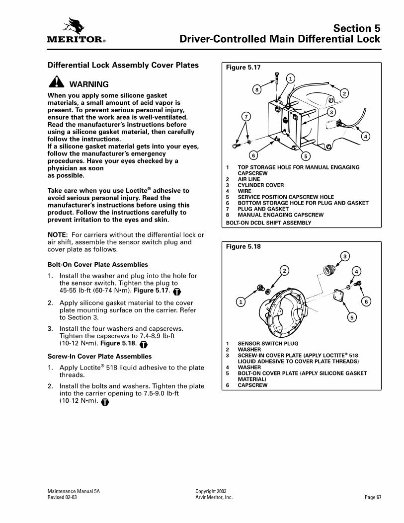
Section 5Driver-Controlled Main Differential Lock
Maintenance Manual 5A Copyright 2003Revised 02-03 ArvinMeritor, Inc. Page 67
Differential Lock Assembly Cover Plates
WARNING
When you apply some silicone gasket materials, a small amount of acid vapor is present. To prevent serious personal injury, ensure that the work area is well-ventilated. Read the manufacturer’s instructions before using a silicone gasket material, then carefully follow the instructions. If a silicone gasket material gets into your eyes, follow the manufacturer’s emergency procedures. Have your eyes checked by a physician as soon as possible.
Take care when you use Loctite
®
adhesive to avoid serious personal injury. Read the manufacturer’s instructions before using this product. Follow the instructions carefully to prevent irritation to the eyes and skin.
NOTE:
For carriers without the differential lock or air shift, assemble the sensor switch plug and cover plate as follows.
Bolt-On Cover Plate Assemblies
1. Install the washer and plug into the hole for the sensor switch. Tighten the plug to45-55 lb-ft (60-74 N•m).
Figure 5.17
.
2. Apply silicone gasket material to the cover plate mounting surface on the carrier. Refer to Section 3.
3. Install the four washers and capscrews. Tighten the capscrews to 7.4-8.9 lb-ft (10-12 N•m).
Figure 5.18
.
Screw-In Cover Plate Assemblies
1. Apply Loctite
®
518 liquid adhesive to the plate threads.
2. Install the bolts and washers. Tighten the plate into the carrier opening to 7.5-9.0 lb-ft (10-12 N•m).
T
T
T
Figure 5.17
1 TOP STORAGE HOLE FOR MANUAL ENGAGING CAPSCREW
2 AIR LINE3 CYLINDER COVER4 WIRE5 SERVICE POSITION CAPSCREW HOLE6 BOTTOM STORAGE HOLE FOR PLUG AND GASKET7 PLUG AND GASKET8 MANUAL ENGAGING CAPSCREW
BOLT-ON DCDL SHIFT ASSEMBLY
Figure 5.18
1 SENSOR SWITCH PLUG2 WASHER3 SCREW-IN COVER PLATE (APPLY LOCTITE
®
518 LIQUID ADHESIVE TO COVER PLATE THREADS)
4 WASHER5 BOLT-ON COVER PLATE (APPLY SILICONE GASKET
MATERIAL)6 CAPSCREW
1
2
3
4
56
7
8
1
2
3
4
5
6

Section 5Driver-Controlled Main Differential Lock
Copyright 2003 Maintenance Manual 5APage 68 ArvinMeritor, Inc. Revised 02-03
Install the Carrier into Axle Housing
WARNING
Solvent cleaners can be flammable, poisonous and cause burns. Examples of solvent cleaners are carbon tetrachloride, and emulsion-type and petroleum-base cleaners. Read the manufacturer’s instructions before using a solvent cleaner, then carefully follow the instructions. Also follow the procedures below.
O Wear safe eye protection.
O Wear clothing that protects your skin.
O Work in a well-ventilated area.
O Do not use gasoline, or solvents that contain gasoline. Gasoline can explode.
O You must use hot solution tanks or alkaline solutions correctly. Read the manufacturer’s instructions before using hot solution tanks and alkaline solutions. Then carefully follow the instructions.
1. Use a cleaning solvent and rags to clean the inside of the axle housing and the mounting surface. Blow dry the cleaned areas with compressed air. Refer to Section 3.
2. Inspect the axle housing for damage.If necessary, repair or replace the housing. Refer to Section 3.
3. Check for loose studs in the mounting surface of the housing where the carrier fastens. Remove and replace any studs where required.
4. Install the differential carrier into the housing, using the Manual Engaging Method.
Manual Engaging Method
1. Align the splines of the shift collar and the differential case half by hand or by installing the right-hand axle shaft through the shift collar and into the side gear.
2. Install the manual engaging capscrew into the threaded hole in the center of thecylinder cover.
CAUTION
There will be a small amount of spring resistance when you turn in the manual engaging capscrew. If a high resistance is felt before reaching the locked or engaged position, stop turning the capscrew. Damage to components can result.
3. Turn the manual adjusting capscrew to the right until the distance from the head of the capscrew is approximately 0.25-0.50-inch(6-13 mm) from the cylinder cover. Do not turn the capscrew beyond its normal stop. When the capscrew head is in the service position 0.25-0.50-inch (6-13 mm) from top of DCDL, the main differential lock is manually engaged.
A high resistance on the capscrew indicates that the splines of the shift collar and the differential case half are not aligned or engaged.
Lift the shift collar as required and rotate to align the splines of collar and case half while turning the manual engaging capscrew inward. When the normal amount of spring resistance is again felt on the capscrew, the splines are engaged. Continue to turn in the manual engaging capscrew until the0.25-0.50-inch (6-13 mm) service position is achieved.
4. Clean both the DCDL actuator and the housing mounting surfaces.
WARNING
When you apply some silicone gasket materials, a small amount of acid vapor is present. To prevent serious personal injury, ensure that the work area is well-ventilated. Read the manufacturer’s instructions before using a silicone gasket material, then carefully follow the instructions. If a silicone gasket material gets into your eyes, follow the manufacturer’s emergency procedures. Have your eyes checked by a physician as soon as possible.
5. Apply silicone gasket material to the cleaned housing surface for the DCDL actuator. Refer to Section 3.
6. Remove the short plug and gasket from the storage hole of the DCDL.
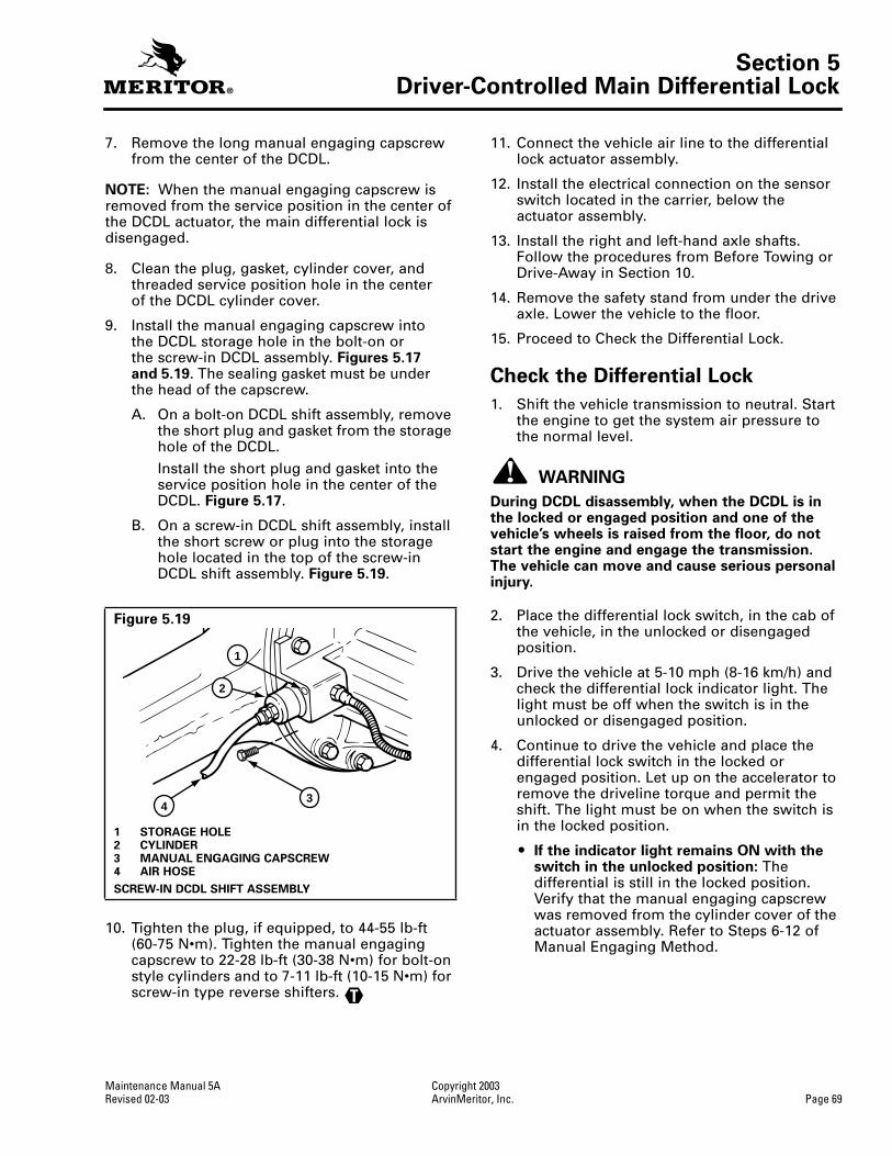
Section 5Driver-Controlled Main Differential Lock
Maintenance Manual 5A Copyright 2003Revised 02-03 ArvinMeritor, Inc. Page 69
7. Remove the long manual engaging capscrew from the center of the DCDL.
NOTE:
When the manual engaging capscrew is removed from the service position in the center of the DCDL actuator, the main differential lock is disengaged.
8. Clean the plug, gasket, cylinder cover, and threaded service position hole in the center of the DCDL cylinder cover.
9. Install the manual engaging capscrew intothe DCDL storage hole in the bolt-on or the screw-in DCDL assembly.
Figures 5.17 and 5.19
. The sealing gasket must be under the head of the capscrew.
A. On a bolt-on DCDL shift assembly, remove the short plug and gasket from the storage hole of the DCDL.
Install the short plug and gasket into the service position hole in the center of the DCDL.
Figure 5.17
.
B. On a screw-in DCDL shift assembly, install the short screw or plug into the storage hole located in the top of the screw-in DCDL shift assembly.
Figure 5.19
.
10. Tighten the plug, if equipped, to 44-55 lb-ft (60-75 N•m). Tighten the manual engaging capscrew to 22-28 lb-ft (30-38 N•m) for bolt-on style cylinders and to 7-11 lb-ft (10-15 N•m) for screw-in type reverse shifters.
11. Connect the vehicle air line to the differential lock actuator assembly.
12. Install the electrical connection on the sensor switch located in the carrier, below the actuator assembly.
13. Install the right and left-hand axle shafts. Follow the procedures from Before Towing or Drive-Away in Section 10.
14. Remove the safety stand from under the drive axle. Lower the vehicle to the floor.
15. Proceed to Check the Differential Lock.
Check the Differential Lock
1. Shift the vehicle transmission to neutral. Start the engine to get the system air pressure to the normal level.
WARNING
During DCDL disassembly, when the DCDL is in the locked or engaged position and one of the vehicle’s wheels is raised from the floor, do not start the engine and engage the transmission. The vehicle can move and cause serious personal injury.
2. Place the differential lock switch, in the cab of the vehicle, in the unlocked or disengaged position.
3. Drive the vehicle at 5-10 mph (8-16 km/h) and check the differential lock indicator light. The light must be off when the switch is in the unlocked or disengaged position.
4. Continue to drive the vehicle and place the differential lock switch in the locked or engaged position. Let up on the accelerator to remove the driveline torque and permit the shift. The light must be on when the switch is in the locked position.
O
If the indicator light remains ON with the switch in the unlocked position:
The differential is still in the locked position. Verify that the manual engaging capscrew was removed from the cylinder cover of the actuator assembly. Refer to Steps 6-12 of Manual Engaging Method.
Figure 5.19
1 STORAGE HOLE2 CYLINDER3 MANUAL ENGAGING CAPSCREW4 AIR HOSE
SCREW-IN DCDL SHIFT ASSEMBLY
1
43
2
1002870a
T

Section 5Driver-Controlled Main Differential Lock
Copyright 2003 Maintenance Manual 5APage 70 ArvinMeritor, Inc. Revised 02-03
Driver Caution Label
Verify that the driver caution label is installed in the vehicle cab. The caution label must be placed in a location that is easily visible to the driver. The recommended location is on the instrument panel, next to the differential lock switch and lock indicator light. Figure 5.20.
Driver caution labels, TP-86101, are available from ArvinMeritor’s Commercial Vehicle Aftermarket. To obtain labels, refer to the Service Notes page on the front inside cover of this manual.
Traction Control Videos
Traction Controls contains two videos — the all-new Splitting the Difference and Driver-Controlled, Full-Locking Main Differential. The videos are also available in CD format.
Driver-Controlled, Full-Locking Main Differential is one of the industry’s best videos on the operation of the main differential. The video explains in full detail how this system works and further discusses the advantages of Meritor’s unique traction control device — DCDL. Testimonials from a large North American fleet support the ease of use of the DCDL.
Also included are several technical pieces to supplement the videos by providing detailed instructions on operating the DCDL and IAD, driver instructions and the difference between the two systems.
To obtain these videos, refer to the Service Notes page on the front inside cover of this manual.
Figure 5.20
CAUTION
ENGAGE FULL LOCKING DIFFERENTIAL ONLYUNDER POOR TRACTION CONDITIONS.
DO NOT USE DURING DOWNHILL OPERATION.DO NOT USE AT SPEEDS ABOVE 25 M.P.H.
WHEN ENGAGED, YOUR VEHICLE’S STEERING CHARACTERISTICSWILL BE AFFECTED. THIS “UNDERSTEER” CONDITION REQUIRES
CAREFUL DRIVING PROCEDURES.
WHEN DISENGAGED, NORMAL VEHICLE HANDLING WILL RESUME.
TP-86101
For further information on this system, see your vehicle operator’s manual or Meritor Driver Instruction Kit TP-9646.
This vehicle is equipped with theMERITOR DRIVER CONTROLLED FULL LOCKING DIFFERENTIAL.

Section 6Lubrication
Maintenance Manual 5A Copyright 2003Revised 02-03 ArvinMeritor, Inc. Page 71
Section 6Lubrication
NOTE:
For complete information on lubricating drive axles and carriers, refer to Maintenance Manual 1, Lubrication. To obtain this publication, refer to the Service Notes page on the front inside cover of this manual.
Refer to
Table G
,
Table H
and
Table I
for standard information on lubricants, schedules and capacities.
Table G: Lubricant Cross Reference (Viscosity) and Temperature Chart
Table H: Oil Change Intervals and Specifications for All Front Drive and Rear Drive Axles
a
Meritor Lubricant Specification Description Cross Reference
Minimum Outside Temperature
Maximum Outside Temperature
O-76-A Hypoid Gear Oil GL-5, S.A.E. 85W/140 +10°F (–12.2°C) - - -*
O-76-B Hypoid Gear Oil GL-5, S.A.E. 80W/140 –15°F (–26.1°C) - - -*
O-76-D Hypoid Gear Oil GL-5, S.A.E. 80W/90 –15°F (–26.1°C) - - -*
O-76-E Hypoid Gear Oil GL-5, S.A.E. 75W/90 –40°F (–40°C) - - -*
O-76-J Hypoid Gear Oil GL-5, S.A.E. 75W –40°F (–40°C) +35°F (+1.6°C)
O-76-L Hypoid Gear Oil GL-5, S.A.E. 75W/140 –40°F (–40°C) - - -*
*There is no upper limit on these outside temperatures, but the axle sump temperature must never exceed 250°F (+121°C).
Vocation or Vehicle Operation
Linehaul Motorhome Intercity Coach
City Delivery School Bus Fire Truck
Construction Transit Bus Refuse Yard Tractor Logging Heavy HaulMiningOil FieldRescue
Initial Oil Change
No longer required as of January 1, 1993
Check Oil Level and Breather
Every 25,000 miles (40 000 km) or the fleet maintenance interval, whichever comes first
Every 10,000 miles (16 000 km), once a month or the fleet maintenance interval, whichever comes first
Every 5,000 miles (8000 km), once a month or the fleet maintenance interval, whichever comes first
b
Petroleum based oil change on axle WITH or WITHOUT pump and filter system
Every 100,000 miles (160 000 km) or annually, whichever comes first
Every 50,000 miles (80 000 km) or annually, whichever comes first
Every 25,000 miles (40 000 km) or annually, whichever comes first
Synthetic oil change on axle WITHOUT pump and filter system
c
Every 250,000 miles(400 000 km) or 3 years, whichever comes first
Every 100,000 miles (160 000 km) or annually, whichever comes first
Every 50,000 miles (80 000 km) or annually, whichever comes first
Synthetic oil change onaxle WITH pump and filter system
c
Every 500,000 miles (800 000 km)
Every 250,000 miles (400 000 km)
Every 100,000 miles (160 000 km)
Filter change on axle with pump and filter system
Every 100,000 miles (160 000 km)
Every 100,000 miles(160 000 km)
Every 100,000 miles (160 000 km)
a
If a No-Spin differential is installed, change the oil, petroleum or synthetic, at a minimum interval of 40,000 miles (64 000 km) or a maximum interval of 50,000 miles (80 000 km).
b
For continuous heavy-duty operation, check the oil level every 1,000 miles (1600 km). Add the correct type and amount of oil as required.
c
This interval applies to approved semi-synthetic and full synthetic oils only. For a list of approved extended-drain axle oils, refer to TP-9539, Approved Rear Drive Axle Lubricants. To obtain this publication, refer to the Service Notes page on the front inside cover of this manual.

Section 6Lubrication
Copyright 2003 Maintenance Manual 5APage 72 ArvinMeritor, Inc. Revised 02-03
Lubricant Capacities
Use the following lubricant capacities as a guide only. The capacities are measured with the drive pinion in the horizontal position. When the angle of the drive pinion changes, the lubricant capacity of the axle will change.
Table I
Axle Model
Capacity
U.S. Pints Liters*
Single Drive Axles
MX-10-120 16.0 7.6
MX-12-120 16.0 7.6
MX-14-120 16.0 7.6
MX-16-120 16.0 7.6
MX-21-160/160R 43.0 20.0
MX-23-160/160R 43.0 20.0
RF-7-120 15.3 7.2
RF-9-120 15.3 7.2
RF-12-120 15.3 7.2
RF-12-125 15.3 7.2
RF-16-145 36.4 17.2
RF-21-155 27.9 13.2
RF-21-156 27.9 13.2
RF-21-160 43.7 20.7
RF-21-185 39.3 18.6
RF-21-355 28.0 13.2
RF-22-166 43.7 20.7
RF-23-180 39.3 18.6
RF-23-185 39.3 18.6
RS-13-120 15.0 7.2
RS-15-120 15.0 7.2
RS-16-140 33.6 15.9
RS-16-141 33.6 15.9
RS-16-145 33.6 15.9
RS-17-140 32.0 15.4
RS-17-141 33.6 15.9
RS-17-144 32.3 15.3
RS-17-145 33.6 15.9
RS-19-144 32.3 15.3
RS-19-145 36.0 17.3
RS-21-145 35.0 16.9
RS-21-160 39.5 18.7
RS-23-160 43/41 20.7/19.5
RS-23-160A 39.5 18.7
RS-23-161/161A 37.2 17.6
RS-23-180 39.0 18.6
RS-23-185 39.0 18.6
RS-23-186 39.0 18.6
RS-25-160 39.0 18.6
Axle Model
Capacity
U.S. Pints Liters*
Single Drive Axles
RS-25-160A 37.2 17.6
RS-26-160 51.0 24.2
RS-26-180 38.0 18.3
RS-26-185 38.0 18.3
RS-30-180 38.0 18.3
RS-30-185 38.0 18.3
* Includes 1 pint (0.97 liter) for each wheel end and with drive pinion angle at 3°.
Axle Model
Capacity
U.S. Pints Liters
Rear Axle of Tandems
RT-34-140 (RR-17-140) 35.0 16.9
RT-34-144 25.8 12.2
RT-34-145 (RR-17-145 rear) 36.0 17.1
RT-34-145P 25.4 12.0
RT-34-146 25.4 12.0
RT-40-140 (RR-20-140) 35.0 16.9
RT-40-145/149 (RR-20-145 rear) 36.0 17.3
RT-40-145P 25.8 12.2
RT-40-146 25.8 12.2
RT-40-160 34.4 16.3
RT-40-169 34.4 16.3
RT-44-145 (RR-22-145 rear) 35.0 16.9
RT-44-145P 25.1 11.9
RT-46-160/169 (RR-23-160 rear) 43/41 20.7/19.5
RT-46-160A/160P 34.4 16.3
RT-46-164 33.2 15.7
RT-46-164EH/16HEH 33.2 15.7
RT-48-180 (RR-24-180 rear) 39.0 18.6
RT-50-160/160P 33.2 15.7
RT-52-160 (RR-26-160 rear) 51.0 24.2
RT-52-180/185 (RR-26-180 rear) 39.0 18.3
RT-58-180/185 (RR-29-180 rear) 39.0 18.3

Section 7Fastener Torque Information
Maintenance Manual 5A Copyright 2003Revised 02-03 ArvinMeritor, Inc. Page 73
Section 7Fastener Torque InformationTorque Values for Fasteners
General Information
1. The torque values in Table J are for fasteners that have a light application of oil on the threads.
O If the fasteners are dry: Increase the torque values by 10%.
O If the fasteners have a heavy application ofoil on the threads: Decrease the torque values by 10%.
2. If you do not know the size of the fastener that is being installed, measure the fastener. Use the following procedure.
American Standard Fasteners
A. Measure the diameter of the threads in inches, dimension X. Figure 7.1.
B. Count the amount of threads in 1-inch. Figure 7.1.
Example
O American Standard size fastener is 0.50-13.
— 0.50 is the diameter of the fastener in inches or dimension X.
— 13 is the amount of threads in 1-inch.
Metric Fasteners
A. Measure the diameter of the threads in millimeters (mm), dimension X. Figure 7.2.
B. Measure the distance of 10 threads, point to point in millimeters (mm), dimension Y. Make a note of dimension Y. Figure 7.2.
C. Divide dimension Y by 10. The result will be the distance between two threads or pitch.
Example
O Metric size fastener is M8 x 1.25.
— M8 is the diameter of the fastener in millimeters (mm) or dimension X.
— 1.25 is the distance between two threads or pitch.
3. Compare the size of fastener measured inStep 2 to the list of fasteners in Table J to find the correct torque value.
Figure 7.1
1 AMOUNT OF THREADS IN 1"2 1"3 X
X DIMENSION = EXAMPLE 1/2"
1
2
3
Figure 7.2
1 PITCH2 X3 Y
X DIMENSION = EXAMPLE M8 OR 8 MM
Y DIMENSION = DISTANCE OF 10 THREADS
2
3
1

Section 7Fastener Torque Information
Copyright 2003 Maintenance Manual 5APage 74 ArvinMeritor, Inc. Revised 02-03
Figure 7.3
4000262a
9
8
10
13
11
15
14
25
12
6
22
16
2624 18
19
21
21
23
20
17
10
7
1
2
3
4
5

Section 7Fastener Torque Information
Maintenance Manual 5A Copyright 2003Revised 02-03 ArvinMeritor, Inc. Page 75
Table J: Torque Chart
Fastener Thread Size Torque Value lb-ft (N•m)
1. Capscrew, Axle Shaft .31-24.50-13
18-2485-115
(24-33)(115-156)
2. Nut, Axle Shaft Stud Plain Nut.44-20.50-20.56-18.62-18Lock Nut.44-20.50-20.56-18.62-18
50-7575-115110-165150-230
40-6565-100100-145130-190
(68-102)(102-156)(149-224)(203-312)
(54-88)(88-136)(136-197)(176-258)
3. Breather .38-18 20 minimum (27 minimum)4. Plug, Oil Fill, Housing .75-14 35 minimum (47.5 minimum)5. Plug, Heat Indicator .50-14 25 minimum (34 minimum)6. Plug, Oil Drain .50-14 25 minimum (34 minimum)7. Capscrew, Differential Case
Grade 10.9 Flange HeadGrade 10.9 Standard Hex HeadGrade 12.9 Standard Hex HeadGrade 12.9 Flange HeadGrade 12.9 Standard Head
.38-16
.44-14
.50-13
.56-12
.62-11M12 x 1.75M12 x 1.75M12 x 1.75M16 x 2M16 x 2
35-5060-7585-115130-165180-23085-10374-96105-125203-251220-310
(48-68)(81-102)(115-156)(176-224)(244-312)(115-140)(100-130)(143-169)(275-340)(300-420)
8. Nut, Differential Case Bolt .50-13.50-20.62-11.62-18M12 x 1.75M16 x 2
75-10085-115150-190180-23074-96220-310
(102-136)(115-156)(203-258)(244-312)(100-130)(300-420)
9. Nut, Ring Gear Bolt
Flange HeadStandard Hex Head
.50-13
.50-20
.62-11
.62-18M12 x 1.25M12 x 1.75M16 x 1.5M16 x 1.5
75-10085-115150-190180-23066-8177-85192-214196-262
(102-136)(115-156)(203-258)(244-312)(90-110)(104-115)(260-190)(265-355)
10. Capscrew, Bearing Cap .56-12.62-11.75-10.88-14.88-9M16 x 2M20 x 2.5M22 x 2.5
110-145150-190270-350360-470425-550181-221347-431479-597
(149-197)(203-258)(366-475)(488-637)(576-746)(245-300)(470-585)(650-810)
11. Nut, Housing to Carrier Stud .44-20.50-20.56-18.62-18
50-7575-115110-165150-230
(68-102)(102-156)(149-224)(203-312)
12. Capscrew, Carrier to Housing .44-14.50-13.56-12.62-11.75-10M12 x 1.75M16 x 2
50-7575-115110-165150-230270-40074-89181-221
(68-102)(102-156)(149-224)(203-312)(366-542)(100-120)(245-300)

Section 7Fastener Torque Information
Copyright 2003 Maintenance Manual 5APage 76 ArvinMeritor, Inc. Revised 02-03
Table J: Torque Chart, Continued
Torque Values are for Carriers with Bolt-On Style Differential Lock Cylinders
Torque Values are for Carriers with Screw-In Style Differential Lock Cylinders
Table K: Input and Output Yoke Pinion Nut Fastener Torque Specifications
Single and Rear of Tandem Axles
Fastener Thread Size Torque Value lb-ft (N•m)
13. Jam Nut, Thrust Screw .75-16.88-141.12-16M22 x 1.5M30 x 1.5
150-190150-300150-190148-210236-295
(203-258)(203-407)(203-258)(200-285)(320-400)
14. Input Yoke-to-Input Shaft Nut Refer to
Table K
.
15. Capscrew, Bearing Cage .38-16.44-14.50-13.56-12.62-11M12 x 1.75
30-5050-7575-115110-165150-23070-110
(41-68)(68-102)(102-156)(149-224)(203-312)(90-150)
16. Plug, Oil Fill, Carrier .75-141.5-11.5M24 x 1.5
25 minimum (34 minimum)120 minimum (163 minimum)35 minimum (47 minimum)
17. Capscrew, Lock Plate .31-18M8 x 1.25
20-3021-26
(27-41)(28-35)
Fastener Thread Size Torque Value lb-ft (N•m)
18. Capscrew, Manual Actuation, Storage Position M10 x 1.5 15-25 (20-35)
19. Adapter, Air Cylinder M12 x 1.5 22-30 (30-40)
20. Capscrew, Air Cylinder Cover M6 x 1 7-12 (10-16)
21. Capscrew/Plug, Air Cylinder CoverOperating PositionStorage Position
M10 x 1.515-2515-25
(20-35)(20-35)
22. Lock Nut, Sensor Switch M16 x 1 25-35 (35-45)
Fastener Thread Size Torque Value lb-ft (N•m)
23. Capscrew, Manual Actuation, Storage Position M10 x 1.25 7-11 (10-15)
24. Air Cylinder M60 x 2.0 80-100 (109-136)
25. Sensor Switch M16 x 1.0 25-35 (35-45)
26. Screw-In DCDL Cylinder Plug or Cap M60 x 2.0 80-100 (109-136)
AxleModel
Pinion Nut Location
RS-120, RS-125, RS-140 RS-144/145
RF-166, RS-160, RS-161, RS-185, RS-186
RS-210, RS-220, RS-230 RS-240 RS-380
CarrierInput Yoke
Fastener Size
740-920 lb-ft (1000-1245 N•m)
M32 x 1.5
920-1130 lb-ft (1250-1535 N•m)
M39 x 1.5
1000-1230 lb-ft (1350-1670 N•m)
M45 x 1.5
740-920 lb-ft (1000-1245 N•m)
M32 x 1.5
740-920 lb-ft (1000-1245 N•m)
M39 x 1.5
800-1100 lb-ft (1085-1496 N•m)
1-1/2 - 12 UNF

Section 8Adjustments and Specifications
Maintenance Manual 5A Copyright 2003Revised 02-03 ArvinMeritor, Inc. Page 77
Section 8Adjustments and Specifications
Drive Pinion Bearings — Preload (Refer to Section 4)
Drive Pinion — Depth in Carrier (Refer to Section 4)
Hypoid Gear Set — Tooth Contact Patterns (Hand Rolled) (Refer to Section 4)
Main Differential Bearings — Preload (Refer to Section 4)
Main Differential Gears — Rotating Resistance (Refer to Section 4)
Specification
New bearings
15-25 lb-in (1.7-2.8 N•m)
Used bearings
5-25 lb-in (1.7-2.8 N•m)
Adjustment
Preload is controlled by the thickness of the spacer between bearings.
To increase preload, install a thinner spacer To decrease preload, install a thicker spacer
Specification
Install the correct amount of shims between the bearing cage and carrier. To calculate, use old shim pack thickness and new and old pinion cone numbers.
Adjustment
Change the thickness of the shim pack to get a good gear tooth contact pattern.
Specification
Conventional gear set
Toward the toe of the gear tooth and in the center between the top and bottom of the tooth
Generoid gear set
Between the center and toe of the tooth and in the center between the top and bottom of the tooth
Adjustment
Tooth contact patterns are controlled by the thickness of the shim pack between the pinion bearing cage and carrier and by ring gear backlash
To move the contact pattern lower, decrease the thickness of the shim pack under the pinion bearing cage
To move the contact pattern higher, increase the thickness of the shim pack under the pinion bearing cage
To move the contact pattern toward the toe of the tooth, decrease backlash of the ring gear
To move the contact pattern toward the heel of the tooth, increase backlash of the ring gear
Specification
15-35 lb-in (1.7-3.9 N•m)
or
Expansion between bearing caps
RS-140, RS-145 and RS-160 carrier models — 0.002-0.009-inch (0.05-0.229 mm)All other carrier models — 0.006-0.013-inch (0.15-0.33 mm)
Adjustment
Preload is controlled by tightening both adjusting rings after zero end play is reached
Specification
50 lb-ft (68 N•m) torque applied to one side gear

Section 8Adjustments and Specifications
Copyright 2003 Maintenance Manual 5APage 78 ArvinMeritor, Inc. Revised 02-03
Ring Gear — Backlash (Refer to Section 4)
Ring Gear — Runout (Refer to Section 4)
DCDL Sensor Switch — Installation (Refer to Section 4)
Spigot Bearing — Peening on the Drive Pinion (Refer to Section 5)
Specification Ring gears that have a pitch diameter of less than 17-inches (431.8 mm)
Range: 0.008-0.018-inch (0.20-0.46 mm) 0.012-inch (0.30 mm) for a new gear set
Ring gears that have a pitch diameter of 17-inches (431.8 mm) or greater
Range: 0.010-0.020-inch (0.25-0.51 mm) 0.015-inch (0.38 mm) for a new gear set
Adjustment Backlash is controlled by the position of the ring gear. Change backlash within specifications to get a good tooth contact pattern.
To increase backlash, move the ring gear away from the drive pinionTo decrease backlash, move the ring gear toward the drive pinion
Specification 0.008-inch (0.20 mm) maximum
Specification Shift the differential to the locked position. Tighten the sensor switch into the carrier until the test light comes on. Tighten the sensor switch one additional turn and tighten lock nut to correct torque value.
Specification Apply 6,614 lb (3000 kg) load on a 0.375-inch (10 mm) ball. Peen the end of the drive pinion at a minimum of five points. Softening of the pinion stem end by heating may be required.

Section 9Special Tools
Maintenance Manual 5A Copyright 2003Revised 02-03 ArvinMeritor, Inc. Page 79
Section 9Special ToolsCarrier Repair Stand Specifications
To obtain a repair stand, refer to the Service Notes page on the front inside cover of this manual.
Figure 9.1
1 PLATES 8’ LONG X 3/4” THICK X 1-1/4” WIDE WITH A TONGUE TO FIT SLOT IN BAR WELD PLATES TO BAR
2 HANDLE 7” LONG WITH SLOT IN ONE END TO FIT CLAMP SCREW3 BAR 2” DIAMETER X 9” LONG WITH ONE END SLOTTED TO FIT PLATE4 WELD ALL AROUND AFTER PRESSING PLUG IN PIPE5 WELD6 SHAPE AND SIZE OF HOLES TO FIT CARRIER7 23-1/2” CENTER TO CENTER OF PIPE8 CHAMFER END OF PIPE FOR WELDING9 4” DIAMETER PIPE10 PLUG 4” DIAMETER X 7” LONG WITH ONE END TURNED 3” LONG TO FIT PIPE. DRILL 2” HOLE
AND MILL 3/16” WIDE SLOT 2” FROM TOP11 SCREW 3-1/2” LONG X 5/8” DIAMETER WITH FLATS ON END TO FIT HANDLE AND 2-1/2” LENGTH
OF THREAD ON OTHER END12 DRILL 3/8” HOLE THROUGH HANDLE AND SCREW
2
1
4
3
6
5
8
7
10
9
12
11
SPX Kent-Moore
part number J-3409-D

Section 9Special Tools
Copyright 2003 Maintenance Manual 5APage 80 ArvinMeritor, Inc. Revised 02-03
How to Make a Yoke Bar
1. Measure dimensions A and B of the yoke you are servicing. Figure 9.2.
2. Calculate dimensions C and D of the yoke bar by adding 0.125-0.250-inch to dimensions A and B of the yoke. Figure 9.3.
WARNING
Wear safe clothing and eye protection when you use welding equipment. Welding equipment can burn you and cause serious personal injury. Follow the operating instructions and safety procedures recommended by the welding equipment manufacturer.
3. To make the box section, cut and weld 1.0-inch x 2.0-inch mild steel square stock according to dimensions C and D. Figure 9.3.
4. Cut a 4.0-foot x 1.25-inch piece of mild steel round stock to make the yoke bar handle. Center weld this piece to the box section. Figure 9.3.
O To increase yoke bar rigidity: Weld two angle pieces onto the handle. Figure 9.3.
Unitized Pinion Seals and Seal Drivers
Refer to Table L and Figure 9.4 for information on unitized pinion seals and seal drivers.
Figure 9.2
1 YOKE
A
B
1
Figure 9.3
1 YOKE BAR
Figure 9.4
1 SEAL DRIVER2 FASTENER HEADS3 SEAL DRIVER R4422401
C
D
1
Position the seal driver to prevent thedriver spokes from hitting the fastener heads
on the forward tandem output seals.
1
23

Section 9Special Tools
Maintenance Manual 5A Copyright 2003Revised 02-03 ArvinMeritor, Inc. Page 81
Table L: Unitized Pinion Seals and Seal Drivers
Single Models Tandem Models
Meritor Unitized Pinion Seal Seal Installation Location
Meritor Seal Driver
Yoke Seal Diameter Inches
MX-21-160
MX-23-160R
RF-16-145
RF-21-160
RF-22-166
RF-23-185
RS-17-145
RS-19-145
RS-21-145
RS-21-160
RS-23-160 /A
RS-23-161 /A
RS-25-160 /A
RS-23-186
RS-26-185
RS-30-185
RT-34-144 /P
RT-34-145 /P
RT-40-145 /A /P
RT-40-149 /A /P
RT-44-145 /P
RT-40-160 /A /P
RT-40-169 /A /P
RT-46-160 /A /P
RT-46-169 /A /P
RT-46-164EH /P
RT-46-16HEH /P
RT-50-160 /P
RT-52-185*
RT-58-185*
A-1205-R-2592 Tandem Forward Input — 145 models from 11-93 to present
R4422402 3.250
3.255
A-1205-P-2590 Tandem Forward Output — Tandem Forward Input 145 models before 11/93 with seal A-1205-F-2424
R4422401 3.000
3.005
A-1205-N-2588 Tandem and Single Rear Input —145 models
R4422401 3.000
3.005
A-1205-Q-2591 Tandem and Single Rear Input — 160/164/185 models
R4422402 3.250
3.255
To obtain Meritor seal driver KIT 4454, refer to the Service Notes page on the front inside cover of this manual.
* Forward and rear input only.

Section 10Vehicle Towing Instructions
Copyright 2003 Maintenance Manual 5APage 82 ArvinMeritor, Inc. Revised 02-03
Section 10Vehicle Towing InstructionsWARNING
To prevent serious eye injury, always wear safe eye protection when you perform vehicle maintenance or service.
Park the vehicle on a level surface. Block the wheels to prevent the vehicle from moving. Support the vehicle with safety stands. Do not work under a vehicle supported only by jacks. Jacks can slip and fall over. Serious personal injury and damage to components can result.
Before you service a spring chamber, carefully follow the manufacturer’s instructions to compress and lock the spring to completely release the brake. Verify that no air pressure remains in the service chamber before you proceed. Sudden release of compressed air can cause serious personal injury and damage to components.
Engage the parking brake to prevent the vehicle from moving before you begin maintenance or service procedures that require you to be under the vehicle. Serious personal injury can result.
CAUTION
If the vehicle is equipped with a front drive axle, tow the vehicle from the front, with the front wheels off the ground. If this is not possible, you must remove the front drive shaft before towing. Damage to components can result.
Do not use a chisel or wedge to loosen the axle shaft and tapered dowels. Using a chisel or wedge can result in damage to the axle shaft, the gasket and seal, and the axle hub.
NOTE: For complete towing information, refer to Technical Bulletin TP-9579, Driver Instruction Kit. To obtain this publication, refer to the Service Notes page on the front inside cover of this manual.
These instructions supersede all other instructions for the purpose of transporting vehicles for service or new vehicle drive-away dated before April 1995, including those contained in Meritor Maintenance Manuals.
When transporting a vehicle with the wheels of one or both drive axles on the road, it is possible to damage the axles if the wrong procedure is used before transporting begins. Meritor recommends that you use the following procedure.
Type of Axle
These instructions are for vehicles equipped with the following Meritor single or tandem rear drive axles.
O Single Axle, with Driver-Controlled Main Differential Lock (DCDL — Screw-In [threaded] shift assembly)
O Tandem Axle, with Driver-Controlled Main Differential Lock (DCDL — Screw-In [threaded] shift assembly) and with Inter-Axle Differential (IAD)
Before Towing or Drive-Away
1. Park the vehicle on a level surface. Block the wheels to prevent the vehicle from moving.
2. Apply the vehicle parking brakes using the switch inside the cab of the vehicle.
3. Shift the transmission into neutral and start the vehicle’s engine.
4. Shift the DCDL and the IAD to the unlocked or disengaged positions using the switches inside the cab of the vehicle. The indicator lights in the cab will go off.
5. Stop the engine.
NOTE: Remove only the axle shaft(s), shown in Table M at this time, from the axle(s) that will remain on the road when the vehicle is transported.
Table M
6. Remove the stud nuts or capscrews and the washers from the flange of the axle shaft. Figure 10.1.
Single Axles
Remove the left-hand (road side) axle shaft
Tandem AxlesForward Axle:Remove the right-hand (curb side) axle shaftRear Axle:Remove the left-hand (road side) axle shaft
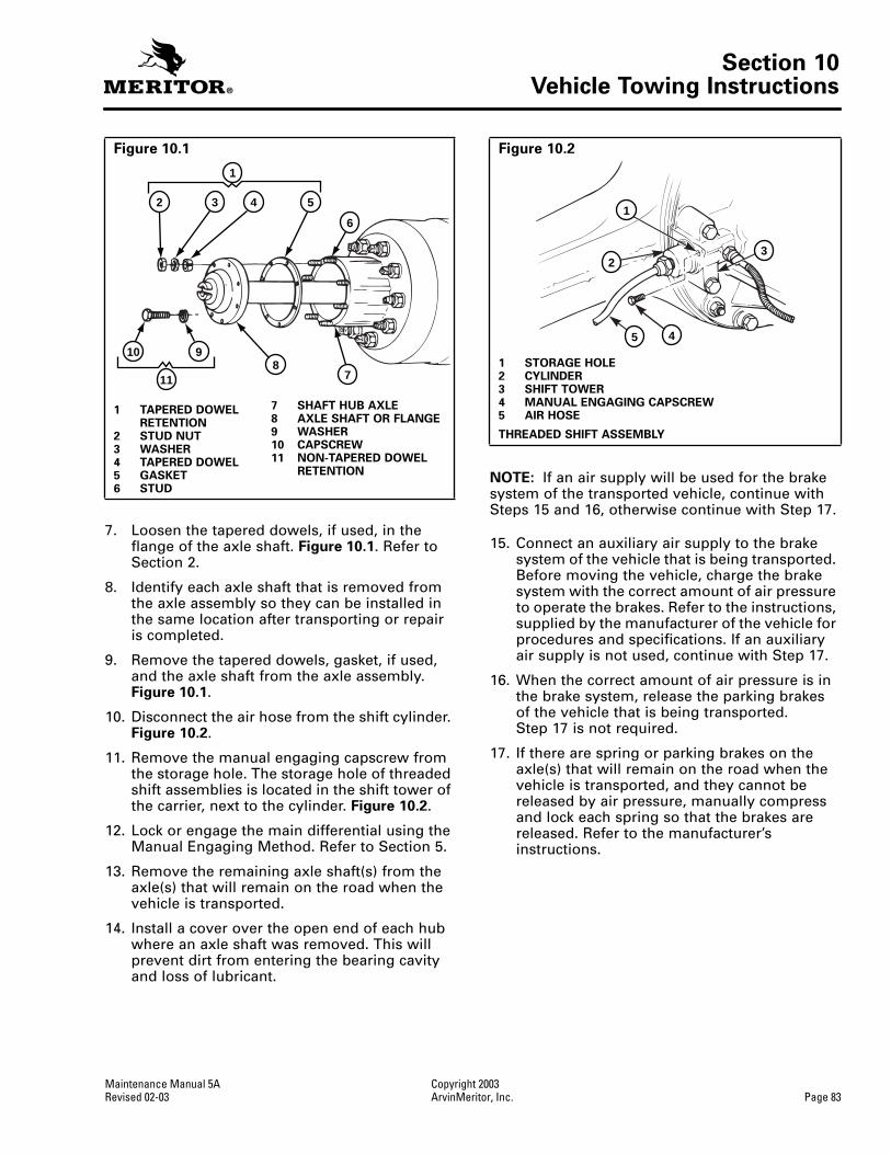
Section 10Vehicle Towing Instructions
Maintenance Manual 5A Copyright 2003Revised 02-03 ArvinMeritor, Inc. Page 83
7. Loosen the tapered dowels, if used, in the flange of the axle shaft. Figure 10.1. Refer to Section 2.
8. Identify each axle shaft that is removed from the axle assembly so they can be installed in the same location after transporting or repair is completed.
9. Remove the tapered dowels, gasket, if used, and the axle shaft from the axle assembly. Figure 10.1.
10. Disconnect the air hose from the shift cylinder. Figure 10.2.
11. Remove the manual engaging capscrew from the storage hole. The storage hole of threaded shift assemblies is located in the shift tower of the carrier, next to the cylinder. Figure 10.2.
12. Lock or engage the main differential using the Manual Engaging Method. Refer to Section 5.
13. Remove the remaining axle shaft(s) from the axle(s) that will remain on the road when the vehicle is transported.
14. Install a cover over the open end of each hub where an axle shaft was removed. This will prevent dirt from entering the bearing cavity and loss of lubricant.
NOTE: If an air supply will be used for the brake system of the transported vehicle, continue with Steps 15 and 16, otherwise continue with Step 17.
15. Connect an auxiliary air supply to the brake system of the vehicle that is being transported. Before moving the vehicle, charge the brake system with the correct amount of air pressure to operate the brakes. Refer to the instructions, supplied by the manufacturer of the vehicle for procedures and specifications. If an auxiliary air supply is not used, continue with Step 17.
16. When the correct amount of air pressure is in the brake system, release the parking brakes of the vehicle that is being transported. Step 17 is not required.
17. If there are spring or parking brakes on the axle(s) that will remain on the road when the vehicle is transported, and they cannot be released by air pressure, manually compress and lock each spring so that the brakes are released. Refer to the manufacturer’s instructions.
Figure 10.1
1 TAPERED DOWEL RETENTION
2 STUD NUT3 WASHER4 TAPERED DOWEL5 GASKET6 STUD
7 SHAFT HUB AXLE8 AXLE SHAFT OR FLANGE9 WASHER10 CAPSCREW11 NON-TAPERED DOWEL
RETENTION
1
2 3 4 5
6
78
910
11
Figure 10.2
1 STORAGE HOLE2 CYLINDER3 SHIFT TOWER4 MANUAL ENGAGING CAPSCREW5 AIR HOSE
THREADED SHIFT ASSEMBLY
1
3
45
2

Section 10Vehicle Towing Instructions
Copyright 2003 Maintenance Manual 5APage 84 ArvinMeritor, Inc. Revised 02-03
After Towing or Drive-Away
1. If an auxiliary air supply was used, apply the vehicle parking brakes using the switch inside the cab of the vehicle. If an auxiliary air supply was not used, begin with Step 2.
2. Apply the vehicle spring or parking brakes by manually releasing each spring that was compressed before transporting started. Refer to the manufacturer’s instructions.
3. Disconnect the auxiliary air supply, if used, from the brake system of the vehicle that was transported. Connect the vehicle’s air supply to the brake system.
4. Remove the covers from the hubs.
NOTE: Install only the axle s haft(s) shown in Table N at this time. These axle shafts have a double row of splines that engage with splines of the side gear and shift collar in the main differential. Figure 10.3.
Table N
5. Install the gasket, if used, and axle shaft into the axle housing and carrier in the same location. The gasket and flange of the axle shaft must be flat against the hub. Rotate the axle shaft or the driveline as necessary to align the splines and the holes in the flange with the studs in the hub. Figure 10.1.
6. Install the dowels, if used, over each stud and into the tapered holes of the flange.
7. Install the washers and capscrews or stud nuts. Determine the size of the fasteners and tighten the capscrews or nuts to the torque value shown in the following table.
Single Axles
Install the right-hand (curb side) axle shaft
Tandem AxlesForward Axle: Install the left-hand (road side) axle shaftRear Axle:Install the right-hand (curb side) axle shaft
Figure 10.3
1 LEFT-HAND, ROAD SIDE, AXLE SHAFT2 SHIFT ASSEMBLY3 SHIFT COLLAR4 RIGHT-HAND, CURB SIDE, AXLE SHAFT5 DOUBLE ROW OF SPLINES6 SHIFT COLLAR AND DIFFERENTIAL CASE SPLINES
ENGAGED OR LOCKED7 SIDE GEAR8 DIFFERENTIAL CASE
SINGLE AXLE OR REAR AXLE OF TANDEM SHOWN WITH SCREW-IN SHIFT ASSEMBLY AND IN THE LOCKED ORENGAGED POSITION
1
2
3
4
5
6
7
8

Section 10Vehicle Towing Instructions
Maintenance Manual 5A Copyright 2003Revised 02-03 ArvinMeritor, Inc. Page 85
8. Unlock or disengage the DCDL by removing the manual engaging capscrew from the shift assembly.
9. Install the manual engaging capscrew into the storage hole. The storage hole of threaded shift assemblies is located in the shift tower of the carrier next to the cylinder. Tighten the capscrew to 15-25 lb-ft (20-35 N•m).
Figure 10.2
.
10. Connect the air hose to the shift cylinder. Tighten the air hose to 22-30 lb-ft (30-40 N•m).
11. Install the remaining axle shaft into the axle housing and carrier.
12. Check the lubricant level in the axles and hubs where the axle shafts were removed. Add the correct type and amount of lubricant if necessary. Refer to Section 6.
Type of Axle
These instructions are for vehicles equipped with the following Meritor single or tandem rear drive axles.
O
Single Axle, with Driver-Controlled Main Differential Lock (DCDL — Bolt-On shift assembly)
O
Tandem Axle, with Driver-Controlled Main Differential Lock (DCDL — Bolt-On shift assembly) and with Inter-Axle Differential (IAD)
Before Towing or Drive-Away
1. Park the vehicle on a level surface. Block the wheels to prevent the vehicle from moving.
2. Apply the vehicle parking brakes using the switch inside the cab of the vehicle.
3. Shift the transmission into neutral and start the vehicle’s engine.
4. Shift the DCDL and the IAD to the unlocked or disengaged positions using the switches inside the cab of the vehicle. The indicator lights in the cab will go off.
5. Stop the engine.
NOTE:
Remove only the axle shaft(s), shown in
Table O
at this time, from the axle(s) that will remain on the road when the vehicle is transported.
Table O
6. Remove the stud nuts or capscrews and the washers from the flange of the axle shaft.
Figure 10.4
.
Fastener Thread SizeTorque Valuelb-ft (N•m)
Capscrews
0.31”-24 0.50”-13
18-24 (24-33) 85-115 (115-156)
Stud Nuts
plain nut 0.44”-200.50”-200.56”-180.62”-180.75”-16
50-75 (68-102)75-115 (102-156)
110-165 (149-224)150-230 (203-312)310-400 (420-542)
lock nut 0.44”-200.50”-200.56”-180.62”-180.75”-16
40-65 (54-88)65-100 (88-136)
100-145 (136-197)130-190 (176-258)270-350 (366-475)
T
T
Single Axles
Remove the left-hand (road side) axle shaft
Tandem Axles
Forward Axle:
Remove the right-hand (curb side) axle shaft
Rear Axle:
Remove the left-hand (road side) axle shaft
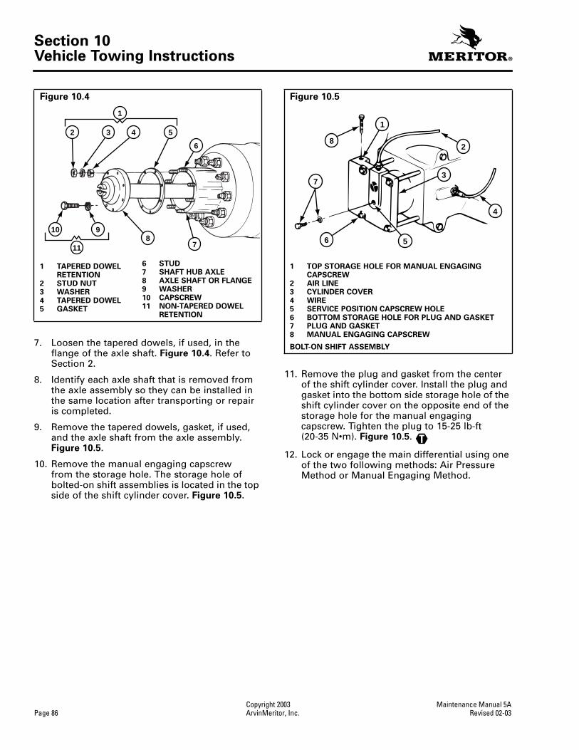
Section 10Vehicle Towing Instructions
Copyright 2003 Maintenance Manual 5APage 86 ArvinMeritor, Inc. Revised 02-03
7. Loosen the tapered dowels, if used, in the flange of the axle shaft.
Figure 10.4
. Refer to Section 2.
8. Identify each axle shaft that is removed from the axle assembly so they can be installed in the same location after transporting or repair is completed.
9. Remove the tapered dowels, gasket, if used, and the axle shaft from the axle assembly.
Figure 10.5
.
10. Remove the manual engaging capscrew from the storage hole. The storage hole of bolted-on shift assemblies is located in the top side of the shift cylinder cover.
Figure 10.5
.
11. Remove the plug and gasket from the center of the shift cylinder cover. Install the plug and gasket into the bottom side storage hole of the shift cylinder cover on the opposite end of the storage hole for the manual engaging capscrew. Tighten the plug to 15-25 lb-ft (20-35 N•m).
Figure 10.5
.
12. Lock or engage the main differential using one of the two following methods: Air Pressure Method or Manual Engaging Method.
Figure 10.4
1 TAPERED DOWEL RETENTION
2 STUD NUT3 WASHER4 TAPERED DOWEL5 GASKET
6 STUD7 SHAFT HUB AXLE8 AXLE SHAFT OR FLANGE9 WASHER10 CAPSCREW11 NON-TAPERED DOWEL
RETENTION
1
2 3 4 5
6
78
910
11
Figure 10.5
1 TOP STORAGE HOLE FOR MANUAL ENGAGING CAPSCREW
2 AIR LINE3 CYLINDER COVER4 WIRE5 SERVICE POSITION CAPSCREW HOLE6 BOTTOM STORAGE HOLE FOR PLUG AND GASKET7 PLUG AND GASKET8 MANUAL ENGAGING CAPSCREW
BOLT-ON SHIFT ASSEMBLY
1
2
3
4
56
7
8
T

Section 10Vehicle Towing Instructions
Maintenance Manual 5A Copyright 2003Revised 02-03 ArvinMeritor, Inc. Page 87
13. Lock or engage the main differential using the air pressure method.
A. Install the manual engaging capscrew into the threaded hole in the center of the cylinder cover. Turn the capscrew to the right three to five turns. Figure 10.7.
B. Shift the transmission into neutral and start the vehicle’s engine. Let the engine idle to increase the pressure in the air system. Do not release the parking brakes.
C. Shift the main differential to the locked or engaged position using the switch inside the cab of the vehicle. When the differential is locked, the indicator light in the cab will go on. If the light does not go on it will be necessary to rotate the main driveline or the IAD by hand until the main differential is locked and the indicator light goes on.
NOTE: When the shift collar is completely engaged with the splines of the main differential case, the differential is locked and the driveline cannot be rotated. Figure 10.6.
D. While the differential is held in the locked position by air pressure, turn the manual engaging capscrew to the right until you feel resistance against the piston. Stop turning the capscrew.
E. Place the main differential lock switch in the unlocked or disengaged position.
F. Stop the engine. Proceed to Step 15.
Figure 10.6
1 LEFT-HAND, ROAD SIDE, AXLE SHAFT2 SHIFT ASSEMBLY3 SHIFT COLLAR4 RIGHT-HAND, CURB SIDE, AXLE SHAFT5 DOUBLE ROW OF SPLINES6 SHIFT COLLAR AND DIFFERENTIAL CASE SPLINES
ENGAGED OR LOCKED7 SIDE GEAR8 DIFFERENTIAL CASE
SINGLE AXLE OR REAR AXLE OF TANDEM SHOWN WITH BOLTED-ON SHIFT ASSEMBLY AND SHOWN IN THE LOCKED OR ENGAGED POSITION
1
2
3
4
56
7
8

Section 10Vehicle Towing Instructions
Copyright 2003 Maintenance Manual 5APage 88 ArvinMeritor, Inc. Revised 02-03
14. Lock or engage the main differential using the manual engaging method.
CAUTION
When you turn the manual engaging capscrew and you feel a high resistance, stop turning the capscrew. A high resistance against the capscrew indicates that the splines of the shift collar and differential case are not aligned. Damage to the threads of the cylinder cover and capscrew will result.
A. Install the manual engaging capscrew into the threaded hole in the center of the cylinder cover. Figure 10.7.
B. Turn the capscrew to the right until the head is approximately 0.25-0.50-inch (6.4-12.7 mm) from the cylinder cover. The capscrew is now in the service position and the main differential is locked or engaged. Figure 10.8. When you turn the capscrew you will feel a small amount of resistance. This is normal.
O If you feel a high resistance before achieving the 0.25-0.50-inch (6.4-12.7 mm) distance between the capscrew head and cylinder: Stop turning the capscrew and continue with Steps C, D and E.
C. Rotate the main driveline or the IAD a small amount by hand.
D. Turn the manual engaging capscrew again to the right. If you still feel a high resistance, stop turning the capscrew.
E. Repeat Steps C and D until you feel a low resistance on the capscrew. Continue with Step B.
15. Remove the remaining axle shaft(s) from the axle(s) that will remain on the road when the vehicle is transported.
16. Install a cover over the open end of each hub where an axle shaft was removed. This will prevent dirt from entering the bearing cavity and loss of lubricant.
NOTE: If an air supply will be used for the brake system of the transported vehicle, continue with Steps 17 and 18. Otherwise continue with Step 19.
17. Connect an auxiliary air supply to the brake system of the vehicle that is being transported. Before moving the vehicle, charge the brake system with the correct amount of air pressure to operate the brakes. Refer to the instructions supplied by the manufacturer of the vehicle for procedures and specifications. If an auxiliary air supply is not used, continuewith Step 19.
18. When the correct amount of air pressure is in the brake system, release the parking brakes of the vehicle that is being transported. Step 19 is not required.
Figure 10.7
1 MANUAL ENGAGING CAPSCREW
BOLT-ON SHIFT ASSEMBLY
Figure 10.8
1 0.25-0.50” (6.4-12.7 MM)
1
1

Section 10Vehicle Towing Instructions
Maintenance Manual 5A Copyright 2003Revised 02-03 ArvinMeritor, Inc. Page 89
19. If there are spring or parking brakes on the axle(s) that will remain on the road when the vehicle is transported, and they cannot be released by air pressure, manually compress and lock each spring so that the brakes are released. Refer to the manufacturer’s instructions.
After Towing or Drive-Away
1. If an auxiliary air supply was used, apply the vehicle parking brakes using the switch inside the cab of the vehicle. If an auxiliary air supply was not used, begin with Step 2.
2. Apply the vehicle spring or parking brakes by manually releasing each spring that was compressed before transporting started. Refer to the manufacturer’s instructions.
3. Disconnect the auxiliary air supply, if used, from the brake system of the vehicle that was transported. Connect the vehicle’s air supply to the brake system.
4. Remove the covers from the hubs.
NOTE:
Install only the axle shaft(s) shown in
Table P
at this time. These axle shafts have a double row of splines that engage with splines of the side gear and shift collar in the main differential.
Figure 10.6
.
Table P
5. Install the gasket, if used, and axle shaft into the axle housing and carrier in the same location. The gasket and flange of the axle shaft must be flat against the hub. Rotate the axle shaft or the driveline as necessary to align the splines and the holes in the flange with the studs in the hub.
Figure 10.4
.
6. Install the dowels, if used, over each stud and into the tapered holes of the flange.
7. Install the washers and capscrews or stud nuts. Determine the size of the fasteners and tighten the capscrews or nuts to the torque value shown in the table below.
8. Unlock or disengage the DCDL by removing the manual engaging capscrew from the shift assembly.
9. Install the manual engaging capscrew into the storage hole. The storage hole of bolted-on shift assemblies is located in the top side of the shift cylinder cover. Tighten the capscrew to 15-25 lb-ft (20-35 N•m).
Figure 10.5
.
10. Remove the plug and gasket from the storage hole. Install the plug and gasket into the threaded hole in the center of the shift cylinder cover. Tighten the plug to 15-25 lb-ft (25-30 N•m).
11. Install the remaining axle shaft into the axle housing and carrier.
12. Check the lubricant level in the axles and hubs where the axle shafts were removed. Add the correct type and amount of lubricant if necessary. Refer to Section 6.
Single Axles
Install the right-hand (curb side) axle shaft
Tandem Axles
Forward Axle:
Install the left-hand (road side) axle shaft
Rear Axle:
Install the right-hand (curb side) axle shaft
Fastener Thread SizeTorque Valuelb-ft (N•m)
Capscrews
0.31”-24 0.50”-13
18-24 (24-33) 85-115 (115-156)
Stud Nuts
plain nut 0.44”-200.50”-200.56”-180.62”-180.75”-16
50-75 (68-102)75-115 (102-156)
110-165 (149-224)150-230 (203-312)310-400 (420-542)
lock nut 0.44”-200.50”-200.56”-180.62”-180.75”-16
40-65 (54-88)65-100 (88-136)
100-145 (136-197)130-190 (176-258)270-350 (366-475)
T
T

Section 10Vehicle Towing Instructions
Copyright 2003 Maintenance Manual 5APage 90 ArvinMeritor, Inc. Revised 02-03
Type of Axle
These instructions are for vehicles equipped with the following Meritor single or tandem rear drive axles.
O Single Axle, without Driver-Controlled Main Differential Lock (DCDL)
O Tandem Axle, without Driver-Controlled Main Differential Lock (DCDL), with Inter-Axle Differential (IAD)
Before Towing or Drive-Away
1. Park the vehicle on a level surface. Block the wheels to prevent the vehicle from moving.
2. Apply the vehicle parking brakes using the switch inside the cab of the vehicle.
NOTE: For a single axle, continue with Step 6. For a tandem axle, continue with Step 3.
3. Shift the transmission into neutral and start the vehicle’s engine.
4. Shift the IAD to the unlocked or disengaged position using the switch inside the cab of the vehicle. The indicator light in the cab will go off.
5. Stop the engine.
NOTE: Remove both axle shafts from the axle(s) that will remain on the road when the vehicle is transported.
6. Remove the stud nuts or capscrews and the washers from the flange of the axle shaft. Figure 10.9.
7. Loosen the tapered dowels, if used, in the flange of the axle shaft. Refer to Section 2. Figure 10.9.
8. Identify each axle shaft that is removed from the axle assembly so they can be installed in the same location after transporting or repair is completed.
9. Remove the tapered dowels, gasket, if used, and the axle shaft from the axle assembly. Figure 10.9.
10. Install a cover over the open end of each hub where an axle shaft was removed. This will prevent dirt from entering the bearing cavity and loss of lubricant.
NOTE: If an air supply will be used for the brake system of the transported vehicle, continue with Steps 11 and 12, otherwise continue with Step 13.
11. Connect an auxiliary air supply to the brake system of the vehicle that is being transported. Before moving the vehicle, charge the brake system with the correct amount of air pressure to operate the brakes. Refer to the instructions supplied by the manufacturer of the vehicle for procedures and specifications. If an auxiliary air supply is not used, continue with Step 13.
12. When the correct amount of air pressure is in the brake system, release the parking brakes of the vehicle that is being transported. Step 13 is not required.
Figure 10.9
1 TAPERED DOWEL RETENTION
2 STUD NUT3 WASHER4 TAPERED DOWEL5 GASKET6 STUD
7 SHAFT HUB AXLE8 AXLE SHAFT OR
FLANGE9 WASHER10 CAPSCREW11 NON-TAPERED DOWEL
RETENTION
1
2 3 4 5
6
78
910
11

Section 10Vehicle Towing Instructions
Maintenance Manual 5A Copyright 2003Revised 02-03 ArvinMeritor, Inc. Page 91
13. If there are spring or parking brakes on the axle(s) that will remain on the road when the vehicle is transported, and they cannot be released by air pressure, manually compress and lock each spring so that the brakes are released. Refer to the manufacturer’s instructions.
After Towing or Drive-Away
1. If an auxiliary air supply was used, apply the vehicle parking brakes using the switch inside the cab of the vehicle. If an auxiliary air supply was not used, begin with Step 2.
2. Apply the vehicle spring or parking brakes by manually releasing each spring that was compressed before transporting started. Refer to the manufacturer’s instructions.
3. Disconnect the auxiliary air supply, if used, from the brake system of the vehicle that was transported. Connect the vehicle’s air supply to the brake system.
4. Remove the covers from the hubs.
5. Install the gasket, if used, and axle shaft into the axle housing and carrier in the same location. The gasket and flange of the axle shaft must be flat against the hub. Rotate the axle shaft or the driveline as necessary to align the splines and the holes in the flange with the studs in the hub.
Figure 10.9
.
6. Install the dowels, if used, over each stud and into the tapered holes of the flange.
7. Install the washers and capscrews or stud nuts. Determine the size of the fasteners and tighten the capscrews or nuts to the torque value shown in the table below.
8. Check the lubricant level in the axles and hubs where the axle shafts were removed. Add the correct type and amount of lubricant if necessary. Refer to Section 6.
Fastener Thread SizeTorque Valuelb-ft (N•m)
Capscrews
0.31”-24 0.50”-13
18-24 (24-33) 85-115 (115-156)
Stud Nuts
plain nut 0.44”-200.50”-200.56”-180.62”-180.75”-16
50-75 (68-102)75-115 (102-156)
110-165 (149-224)150-230 (203-312)310-400 (420-542)
lock nut 0.44”-200.50”-200.56”-180.62”-180.75”-16
40-65 (54-88)65-100 (88-136)
100-145 (136-197)130-190 (176-258)270-350 (366-475)

Notes


Meritor Heavy Vehicle Systems, LLC2135 West Maple RoadTroy, MI 48084 USA800-535-5560arvinmeritor.com
Information contained in this publication was in effect at the time the publication was approved for printing and is subject to change without notice or liability. Meritor Heavy Vehicle Systems, LLC, reserves the right to revise the information presented or discontinue the production of parts described at any time.
Copyright 2003 Maintenance Manual 5AArvinMeritor, Inc. Revised 02-03All Rights Reserved Printed in the USA 16579/24240