single-phase command and control transformers
TRANSCRIPT
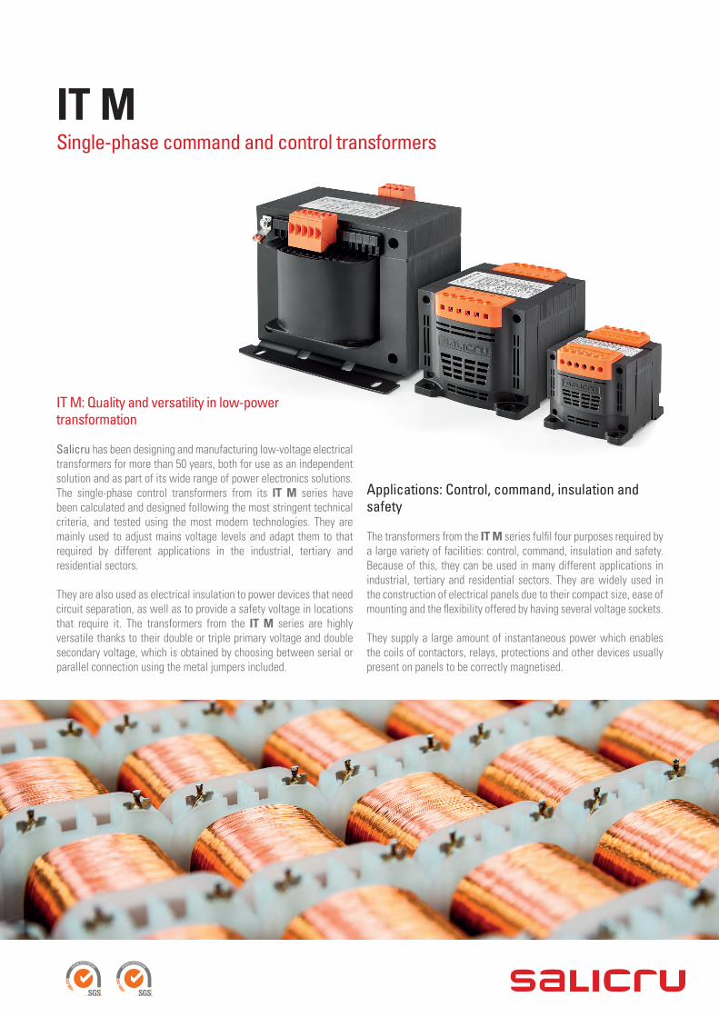
IT MSingle-phase command and control transformers
Applications: Control, command, insulation and safety
The transformers from the IT M series fulfil four purposes required by a large variety of facilities: control, command, insulation and safety. Because of this, they can be used in many different applications in industrial, tertiary and residential sectors. They are widely used in the construction of electrical panels due to their compact size, ease of mounting and the flexibility offered by having several voltage sockets.
They supply a large amount of instantaneous power which enables the coils of contactors, relays, protections and other devices usually present on panels to be correctly magnetised.
IT M: Quality and versatility in low-power transformation
Salicru has been designing and manufacturing low-voltage electrical transformers for more than 50 years, both for use as an independent solution and as part of its wide range of power electronics solutions. The single-phase control transformers from its IT M series have been calculated and designed following the most stringent technical criteria, and tested using the most modern technologies. They are mainly used to adjust mains voltage levels and adapt them to that required by different applications in the industrial, tertiary and residential sectors.
They are also used as electrical insulation to power devices that need circuit separation, as well as to provide a safety voltage in locations that require it. The transformers from the IT M series are highly versatile thanks to their double or triple primary voltage and double secondary voltage, which is obtained by choosing between serial or parallel connection using the metal jumpers included.
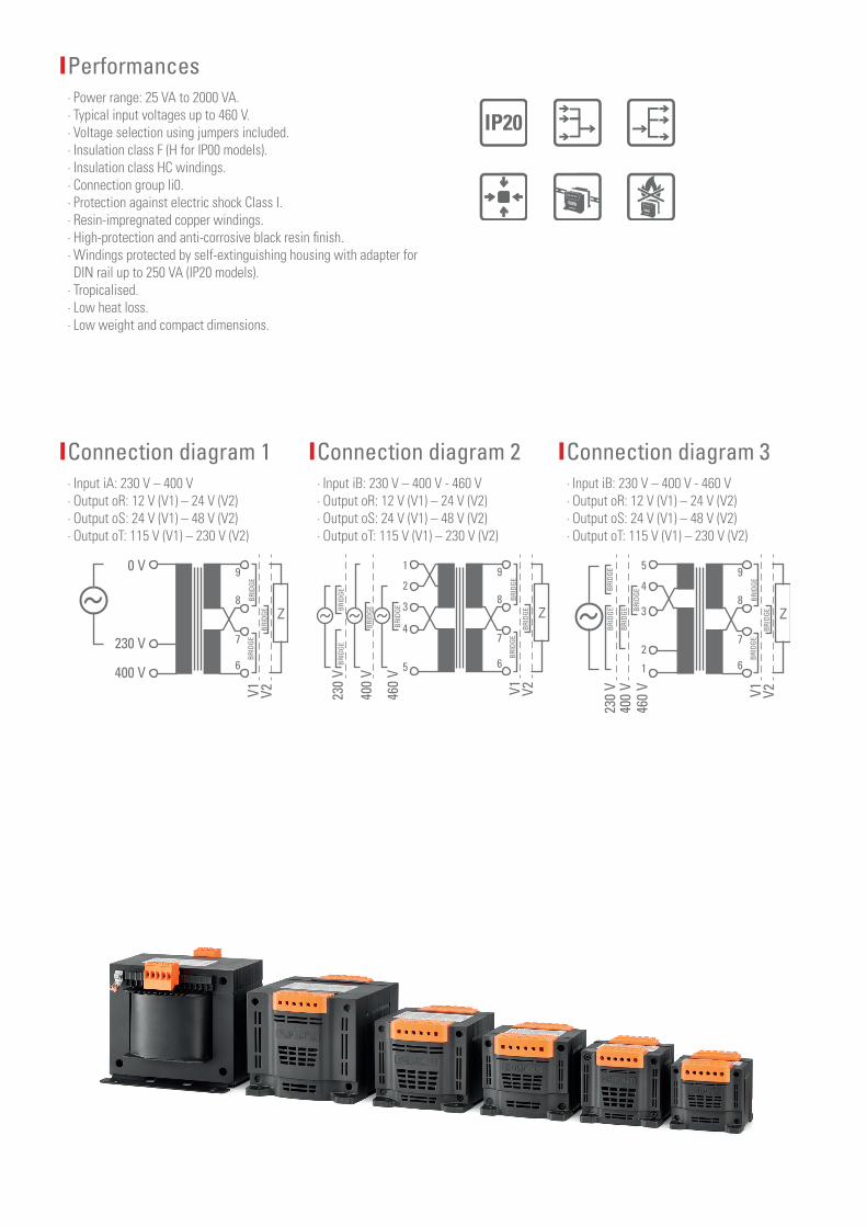
Connection diagram 1 ∙ Input iA: 230 V – 400 V ∙ Output oR: 12 V (V1) – 24 V (V2) ∙ Output oS: 24 V (V1) – 48 V (V2) ∙ Output oT: 115 V (V1) – 230 V (V2)
0 V
230 V
Z
9
8
7
6400 V
V1BR
IDGE
BRID
GE
BRID
GE
V2
Connection diagram 2 ∙ Input iB: 230 V – 400 V - 460 V ∙ Output oR: 12 V (V1) – 24 V (V2) ∙ Output oS: 24 V (V1) – 48 V (V2) ∙ Output oT: 115 V (V1) – 230 V (V2)
400
V
230
V
460
V
Z
91
2
3
4
5
8
7
6
V1BR
IDGE
BRID
GE
BRID
GE
BRID
GE
BRID
GEBRID
GEBR
IDGE
V2
Connection diagram 3 ∙ Input iB: 230 V – 400 V - 460 V ∙ Output oR: 12 V (V1) – 24 V (V2) ∙ Output oS: 24 V (V1) – 48 V (V2) ∙ Output oT: 115 V (V1) – 230 V (V2)
400
V23
0 V
460
V
5
4
3
2
1
BRID
GE
BRID
GE
BRID
GE
BRID
GE Z
9
8
7
6
V1BR
IDGE
BRID
GE
BRID
GE
V2
Performances ∙ Power range: 25 VA to 2000 VA. ∙ Typical input voltages up to 460 V. ∙ Voltage selection using jumpers included. ∙ Insulation class F (H for IP00 models). ∙ Insulation class HC windings. ∙ Connection group Ii0. ∙ Protection against electric shock Class I. ∙ Resin-impregnated copper windings. ∙ High-protection and anti-corrosive black resin finish. ∙ Windings protected by self-extinguishing housing with adapter for DIN rail up to 250 VA (IP20 models). ∙ Tropicalised. ∙ Low heat loss. ∙ Low weight and compact dimensions.
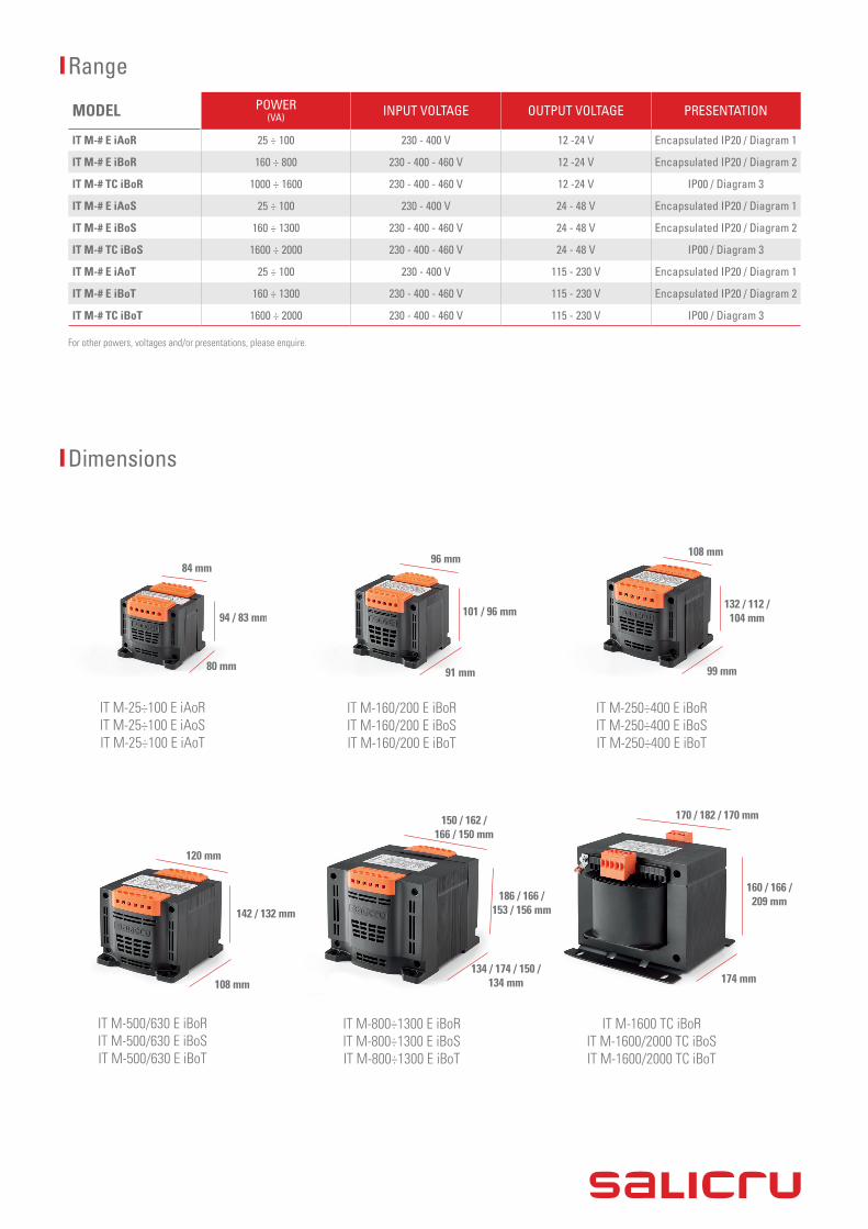
Dimensions
IT M-25÷100 E iAoR IT M-25÷100 E iAoS IT M-25÷100 E iAoT
IT M-500/630 E iBoR IT M-500/630 E iBoS IT M-500/630 E iBoT
84 mm
120 mm
94 / 83 mm
142 / 132 mm
80 mm
108 mm
IT M-160/200 E iBoR IT M-160/200 E iBoS IT M-160/200 E iBoT
IT M-800÷1300 E iBoR IT M-800÷1300 E iBoS IT M-800÷1300 E iBoT
96 mm
150 / 162 / 166 / 150 mm
101 / 96 mm
186 / 166 / 153 / 156 mm
91 mm
134 / 174 / 150 / 134 mm
IT M-250÷400 E iBoR IT M-250÷400 E iBoS IT M-250÷400 E iBoT
IT M-1600 TC iBoR IT M-1600/2000 TC iBoS IT M-1600/2000 TC iBoT
108 mm
170 / 182 / 170 mm
132 / 112 / 104 mm
160 / 166 / 209 mm
99 mm
174 mm
Range
MODEL POWER (VA) INPUT VOLTAGE OUTPUT VOLTAGE PRESENTATION
IT M-# E iAoR 25 ÷ 100 230 - 400 V 12 -24 V Encapsulated IP20 / Diagram 1
IT M-# E iBoR 160 ÷ 800 230 - 400 - 460 V 12 -24 V Encapsulated IP20 / Diagram 2
IT M-# TC iBoR 1000 ÷ 1600 230 - 400 - 460 V 12 -24 V IP00 / Diagram 3
IT M-# E iAoS 25 ÷ 100 230 - 400 V 24 - 48 V Encapsulated IP20 / Diagram 1
IT M-# E iBoS 160 ÷ 1300 230 - 400 - 460 V 24 - 48 V Encapsulated IP20 / Diagram 2
IT M-# TC iBoS 1600 ÷ 2000 230 - 400 - 460 V 24 - 48 V IP00 / Diagram 3
IT M-# E iAoT 25 ÷ 100 230 - 400 V 115 - 230 V Encapsulated IP20 / Diagram 1
IT M-# E iBoT 160 ÷ 1300 230 - 400 - 460 V 115 - 230 V Encapsulated IP20 / Diagram 2
IT M-# TC iBoT 1600 ÷ 2000 230 - 400 - 460 V 115 - 230 V IP00 / Diagram 3
For other powers, voltages and/or presentations, please enquire.

www.linkedin.com/company/salicruen/@salicru_en
AVDA. DE LA SERRA 100 · 08460 PALAUTORDERA · SPAIN · [email protected]+34 938 482 400 WWW.SALICRU.COM
REF. JJ033B01 CODE 401AB001056 ED. DECEMBER 2019 - TRANSFORMERS AND AUTOTRANSFORMERS
Technical specifications
MODEL IT MELECTRICAL Input/Output Single-phase
Power range 25 VA a 2000 VA
Power factor 1
Connection group Ii0 (with jumpers)
INPUT Single phase voltage Pow ≤ 100 VA: 230-400 V / Pow > 100 VA: 230-400-460 V
Rated frequency 50 / 60 Hz
OUTPUT Single phase rated voltage 12-24 V (separation of circuits and safety) / 24-48 V (separation of circuits and safety) / 115-230 V (separation of circuits)
Frequency 50 / 60 Hz
Single phase short-circuit voltage 25 VA: 6,7%; 100 VA: 5,9%; 250 VA: 4,9% 500 VA: 3,3%; 1000 VA: 2,7%; 2000VA: 2%
MANUFACTURE Insulators Insulation class F (140°C) Temp=40°C for models with protection rating IP20 Insulation class B (120°C) Temp=45°C for models with protection rating IP00
Windings Insulation class H (200ºC)
Windings material Copper
Impregnation Synthetic and polymerised resin
Ventilation ANAN
GENERAL Version Pow ≤ 1300 VA (≤ 800 VA for 12-24 V output): Windings protected by self-extingui-shing housing with adapter for DIN rail up to 250 VA.
Pow > 1300 VA (> 800 VA for 12-24 V output): Base plate according to DIN 41308. High-protection, anti-corrosive and tropicalised black resin finish.
Colour (box version) Black with orange terminals
Electrical protection Against electric shock Class I
Degree of protection IP20 for Pow ≤ 1300 VA (≤ 800 VA for 12-24 V output) / IP00 for Pow > 1300 VA (> 800 VA for 12-24 V output)
Test voltage 4.5 kV pri-sec - 2.5 kV sec-earth
Terminal type Screw terminals
STANDARDS Safety EN-61558- Directive 2006/95CEE UNE20324-EN60529
Quality and environmental management ISO 9001 & ISO 14001
Info
rmat
ion
subj
ect t
o ch
ange
with
out n
otic
e.