single expansion joints - hyspan
TRANSCRIPT

3"Single Expansion Joints
FMH EXPANSION JOINTS 1-800-359-4673 • (770) 493-1100 • Fax: (770) 493-1410 • E-mail: [email protected]
Standard materials of constructionBellows: A240 T321.Liners: A240 T304 (when liner is requested).Covers: Carbon Steel (when cover is requested).Flanges: 25 to 150 psig; 150# ANSI B16.5 RFSO (A105).
300 psig; 300# ANSI B16.5 RFSO (A105).Plate Flanges: 5/8" thick; 150# ANSI B16.5 drilling (A-36).Pipe: Standard Wt. (A53-B/A106-B).
*Hardware: Carbon Steel (Tie Rods, Hinges, Gimbals).
• Maximum Test Pressure is 1.5 X Rated Pressure.• Pressure Rating is based on a design temperature of
-20˚ F to 600˚ F. If forged flanged ends are specified, themaximum temperature rating for 150 psig design is 500˚F.
• Consult factory for temperature rating of plate flanges.• Maximum Axial Extension is 15% of Axial Compression
Value shown above.• Cycle Life = 3,000 minimum (EJMA).• Movements are non-concurrent.
* To obtain Bellows Only Overall Length, subtract 6" fromWS - WS length and add neck lengths.
* To obtain Banded Bellows Overall Length, subtract 31/2"from WS - WS length.
* Additional length is required for units with hardwareattached to weld ends (please consult factory).
PART NUMBER EXAMPLE:
This part number describes the unit pictured above.
STNEMEVOM)seerged()sehcni()sehcni(
SETARGNIRPS)ni/sbl()ni/sbl( )ged/bl.ni(
"8/1±SHTGNELLLAREVO*)sehcni(
LAIXA.PMOC LARETAL RALUGNA LAIXA LARETAL RALUGNA
RF-RFRV-RV
PF-PFPV-PV SW-SW
SW-RFSW-RV
SW-PFSW-PV
52gisp
84.0 50.0 01.41 046 0819 02 57.3 05.2 52.7 05.5 00.559.0 12.0 00.51 023 0511 01 00.5 57.3 05.8 57.6 52.6
34.1 64.0 00.51 012 043 01 52.6 00.5 57.9 00.8 05.7
07.11 20.2 39.0 00.51 051 021 01> 57.7 57.6 05.11 05.9 00.9
05gisp
63.0 40.0 86.01 057 00901 03 57.3 05.2 52.7 05.5 00.536.0 21.0 00.51 034 0302 01 57.4 05.3 52.8 05.6 00.6
19.0 42.0 00.51 003 007 01 05.5 05.4 52.9 05.7 57.6
78.11 81.1 14.0 00.51 032 023 01 05.6 05.5 52.01 52.8 57.7
051gisp
43.0 40.0 68.9 0461 06932 05 57.3 05.2 52.7 05.5 00.557.0 81.0 00.51 037 0012 02 52.5 52.4 00.9 00.7 05.6
97.0 72.0 00.51 0221 0961 04 05.6 05.5 52.01 52.8 57.7
99.11 30.1 74.0 00.51 039 067 03 57.7 57.6 05.11 05.9 00.9
003gisp
82.0 40.0 13.8 0023 08523 011 00.5 05.7 52.654.0 90.0 42.31 0102 0418 07 57.5 05.8 52.7
26.0 71.0 00.51 0641 0713 05 57.6 52.9 00.8
99.11 87.0 62.0 00.51 0511 0561 04 05.7 00.01 57.8
MONEZIS
TINUEPYT
TINUELYTS
NGISED.SSERP
LAIXA.PMOC
DNESGNITTIF
)01egaPeeS(
RENIL/W
L'TAM
REVOC/W
L'TAM
LLAREVOHTGNEL
SLAIRETAMLAICEPS
SWOLLEB DNE
L'TAM L'TAM
- - - - - - - -3 S 0 150 0.79 FR FR 61/2" B8
Nominal Diameter
UNIT TYPES = SINGLE
UNIT STYLEB = BELLOWS ONLYO = UNRESTRAINEDT = TIE RODS/LIMIT RODS/
CONTROL RODSH = HINGEG = GIMBAL
➢
➢
*
11

Single Expansion Joints
UNIT TYPES = SINGLE
UNIT STYLEB = BELLOWS ONLYO = UNRESTRAINEDT = TIE RODS/LIMIT RODS/
CONTROL RODSH = HINGEG = GIMBAL
Standard materials of constructionBellows: A240 T321.Liners: A240 T304 (when liner is requested).Covers: Carbon Steel (when cover is requested).Flanges: 25 to 150 psig; 150# ANSI B16.5 RFSO (A105).
300 psig; 300# ANSI B16.5 RFSO (A105).Plate Flanges: 5/8" thick; 150# ANSI B16.5 drilling (A-36).Pipe: Standard Wt. (A53-B/A106-B).
*Hardware: Carbon Steel (Tie Rods, Hinges, Gimbals).
• Maximum Test Pressure is 1.5 X Rated Pressure.• Pressure Rating is based on a design temperature of
-20˚ F to 600˚ F. If forged flanged ends are specified, themaximum temperature rating for 150 psig design is 500˚F.
• Consult factory for temperature rating of plate flanges.• Maximum Axial Extension is 15% of Axial Compression
Value shown above.• Cycle Life = 3,000 minimum (EJMA).• Movements are non-concurrent.
* To obtain Bellows Only Overall Length, subtract 6" fromWS - WS length and add neck lengths.
* To obtain Banded Bellows Overall Length, subtract 31/2"from WS - WS length.
* Additional length is required for units with hardwareattached to weld ends (please consult factory).
PART NUMBER EXAMPLE:
This part number describes the unit pictured above.
4"
STNEMEVOM)seerged()sehcni()sehcni(
SETARGNIRPS)ni/sbl()ni/sbl( )ged/bl.ni(
"8/1±SHTGNELLLAREVO*)sehcni(
LAIXA.PMOC LARETAL RALUGNA LAIXA LARETAL RALUGNA
RF-RFRV-RV
PF-PFPV-PV SW-SW
SW-RFSW-RV
SW-PFSW-PV
52gisp
76.0 80.0 00.51 073 0944 02 05.4 00.3 57.7 52.6 05.500.1 81.0 00.51 052 0331 01 52.5 00.4 57.8 00.7 52.6
05.1 93.0 00.51 061 093 01 57.6 52.5 00.01 52.8 57.7
25.91 38.1 95.0 00.51 031 022 01 05.7 52.6 00.11 52.9 05.8
05gisp
16.0 70.0 96.31 007 0778 04 05.4 00.3 57.7 52.6 05.512.1 82.0 00.51 053 0011 02 52.6 57.4 05.9 00.8 52.7
08.1 26.0 00.51 005 017 03 00.8 05.6 52.11 57.9 00.9
83.02 52.2 79.0 00.51 004 063 02 52.9 00.8 57.21 00.11 52.01
051gisp
34.0 50.0 27.9 0431 04961 08 05.4 00.3 57.7 52.6 05.557.0 51.0 00.51 077 0613 04 57.5 05.4 52.9 05.7 57.6
01.1 13.0 00.51 0811 0142 07 00.7 57.5 05.01 57.8 00.8
54.02 23.1 54.0 00.51 089 0041 06 00.8 05.6 52.11 57.9 00.9
003gisp
34.0 60.0 96.9 0314 08913 042 00.6 52.8 52.706.0 21.0 15.31 0692 06811 071 00.7 52.9 00.8
77.0 02.0 00.51 0032 0365 031 57.7 00.01 00.9
15.02 40.1 73.0 00.51 0271 0822 001 52.9 05.11 05.01
MONEZIS
TINUEPYT
TINUELYTS
NGISED.SSERP
LAIXA.PMOC
DNESGNITTIF
)01egaPeeS(
RENIL/W
L'TAM
REVOC/W
L'TAM
LLAREVOHTGNEL
SLAIRETAMLAICEPS
SWOLLEB DNE
L'TAM L'TAM
- - - - - - - -
FMH EXPANSION JOINTS 1-800-359-4673 • (770) 493-1100 • Fax: (770) 493-1410 • E-mail: [email protected]
4 S 0 150 1.10 WS WS 101/2" B1 E1
Nominal Diameter
➢
➢
*
12
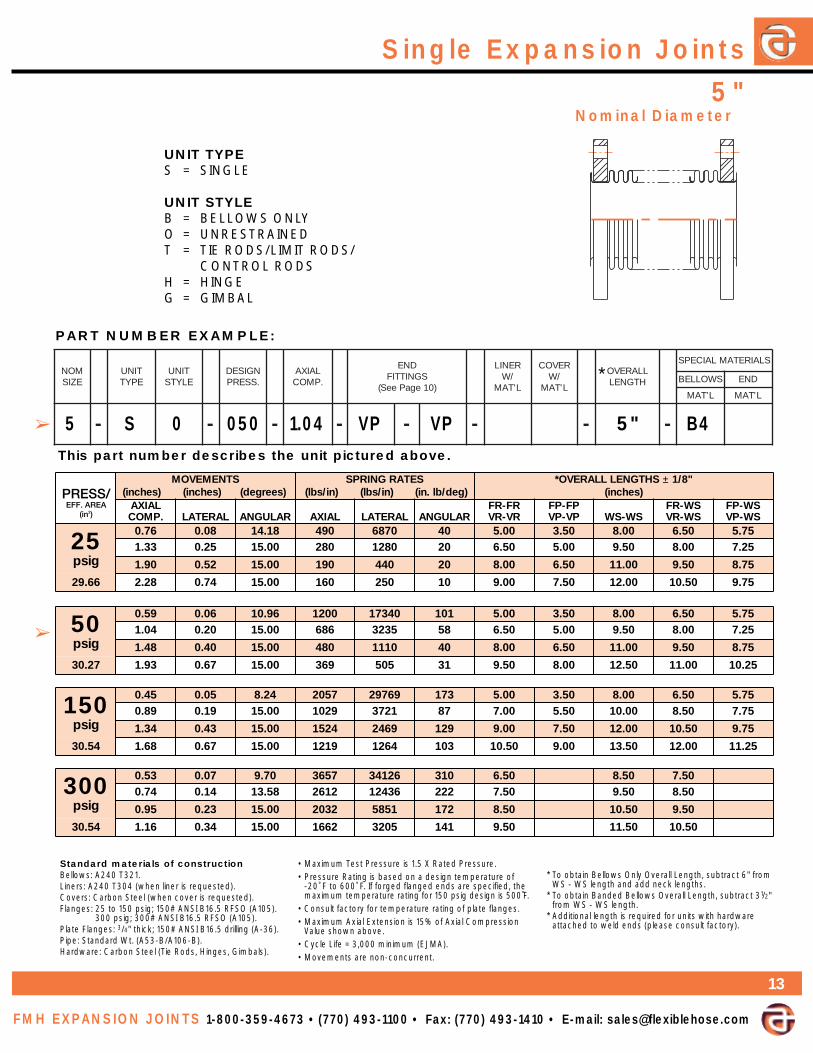
5"Single Expansion Joints
FMH EXPANSION JOINTS 1-800-359-4673 • (770) 493-1100 • Fax: (770) 493-1410 • E-mail: [email protected]
Standard materials of constructionBellows: A240 T321.Liners: A240 T304 (when liner is requested).Covers: Carbon Steel (when cover is requested).Flanges: 25 to 150 psig; 150# ANSI B16.5 RFSO (A105).
300 psig; 300# ANSI B16.5 RFSO (A105).Plate Flanges: 3/4" thick; 150# ANSI B16.5 drilling (A-36).Pipe: Standard Wt. (A53-B/A106-B).
*Hardware: Carbon Steel (Tie Rods, Hinges, Gimbals).
• Maximum Test Pressure is 1.5 X Rated Pressure.• Pressure Rating is based on a design temperature of
-20˚ F to 600˚ F. If forged flanged ends are specified, themaximum temperature rating for 150 psig design is 500˚F.
• Consult factory for temperature rating of plate flanges.• Maximum Axial Extension is 15% of Axial Compression
Value shown above.• Cycle Life = 3,000 minimum (EJMA).• Movements are non-concurrent.
* To obtain Bellows Only Overall Length, subtract 6" fromWS - WS length and add neck lengths.
* To obtain Banded Bellows Overall Length, subtract 31/2"from WS - WS length.
* Additional length is required for units with hardwareattached to weld ends (please consult factory).
PART NUMBER EXAMPLE:
This part number describes the unit pictured above.
STNEMEVOM)seerged()sehcni()sehcni(
SETARGNIRPS)ni/sbl()ni/sbl( )ged/bl.ni(
"8/1±SHTGNELLLAREVO*)sehcni(
LAIXA.PMOC LARETAL RALUGNA LAIXA LARETAL RALUGNA
RF-RFRV-RV
PF-PFPV-PV SW-SW
SW-RFSW-RV
SW-PFSW-PV
52gisp
67.0 80.0 81.41 094 0786 04 00.5 05.3 00.8 05.6 57.533.1 52.0 00.51 082 0821 02 05.6 00.5 05.9 00.8 52.7
09.1 25.0 00.51 091 044 02 00.8 05.6 00.11 05.9 57.8
66.92 82.2 47.0 00.51 061 052 01 00.9 05.7 00.21 05.01 57.9
05gisp
95.0 60.0 69.01 0021 04371 101 00.5 05.3 00.8 05.6 57.540.1 02.0 00.51 686 5323 85 05.6 00.5 05.9 00.8 52.7
84.1 04.0 00.51 084 0111 04 00.8 05.6 00.11 05.9 57.8
72.03 39.1 76.0 00.51 963 505 13 05.9 00.8 05.21 00.11 52.01
051gisp
54.0 50.0 42.8 7502 96792 371 00.5 05.3 00.8 05.6 57.598.0 91.0 00.51 9201 1273 78 00.7 05.5 00.01 05.8 57.7
43.1 34.0 00.51 4251 9642 921 00.9 05.7 00.21 05.01 57.9
45.03 86.1 76.0 00.51 9121 4621 301 05.01 00.9 05.31 00.21 52.11
003gisp
35.0 70.0 07.9 7563 62143 013 05.6 05.8 05.747.0 41.0 85.31 2162 63421 222 05.7 05.9 05.8
59.0 32.0 00.51 2302 1585 271 05.8 05.01 05.9
45.03 61.1 43.0 00.51 2661 5023 141 05.9 05.11 05.01
MONEZIS
TINUEPYT
TINUELYTS
NGISED.SSERP
LAIXA.PMOC
DNESGNITTIF
)01egaPeeS(
RENIL/W
L'TAM
REVOC/W
L'TAM
LLAREVOHTGNEL
SLAIRETAMLAICEPS
SWOLLEB DNE
L'TAM L'TAM
- - - - - - - -5 S 0 050 1.04 VP VP 5" B4
Nominal Diameter
UNIT TYPES = SINGLE
UNIT STYLEB = BELLOWS ONLYO = UNRESTRAINEDT = TIE RODS/LIMIT RODS/
CONTROL RODSH = HINGEG = GIMBAL
➢
➢
*
13

Single Expansion Joints
UNIT TYPES = SINGLE
UNIT STYLEB = BELLOWS ONLYO = UNRESTRAINEDT = TIE RODS/LIMIT RODS/
CONTROL RODSH = HINGEG = GIMBAL
Standard materials of constructionBellows: A240 T321.Liners: A240 T304 (when liner is requested).Covers: Carbon Steel (when cover is requested).Flanges: 25 to 150 psig; 150# ANSI B16.5 RFSO (A105).
300 psig; 300# ANSI B16.5 RFSO (A105).Plate Flanges: 3/4" thick; 150# ANSI B16.5 drilling (A-36).Pipe: Standard Wt. (A53-B/A106-B).
*Hardware: Carbon Steel (Tie Rods, Hinges, Gimbals).
• Maximum Test Pressure is 1.5 X Rated Pressure.• Pressure Rating is based on a design temperature of
-20˚ F to 600˚ F. If forged flanged ends are specified, themaximum temperature rating for 150 psig design is 500˚F.
• Consult factory for temperature rating of plate flanges.• Maximum Axial Extension is 15% of Axial Compression
Value shown above.• Cycle Life = 3,000 minimum (EJMA).• Movements are non-concurrent.
* To obtain Bellows Only Overall Length, subtract 7" fromWS - WS length and add neck lengths.
* To obtain Banded Bellows Overall Length, subtract 41/2"from WS - WS length.
* Additional length is required for units with hardwareattached to weld ends (please consult factory).
PART NUMBER EXAMPLE:
This part number describes the unit pictured above.
6"
STNEMEVOM)seerged()sehcni()sehcni(
SETARGNIRPS)ni/sbl()ni/sbl( )ged/bl.ni(
"8/1±SHTGNELLLAREVO*)sehcni(
LAIXA.PMOC LARETAL RALUGNA LAIXA LARETAL RALUGNA
RF-RFRV-RV
PF-PFPV-PV SW-SW
SW-RFSW-RV
SW-PFSW-PV
52gisp
67.0 70.0 90.21 055 06601 06 52.5 05.3 00.9 52.7 52.633.1 22.0 00.51 013 0991 04 57.6 00.5 05.01 57.8 57.7
09.1 44.0 00.51 022 086 02 52.8 05.6 00.21 52.01 52.9
08.04 82.2 36.0 00.51 081 093 02 52.9 05.7 00.31 52.11 52.01
05gisp
85.0 50.0 80.9 0141 05972 061 52.5 05.3 00.9 52.7 52.610.1 61.0 00.51 018 0225 09 57.6 00.5 05.01 57.8 57.7
85.1 04.0 00.51 015 0431 06 57.8 00.7 05.21 57.01 57.9
15.14 20.2 56.0 00.51 004 056 05 52.01 05.8 00.41 52.21 52.11
051gisp
44.0 40.0 19.6 0142 09384 082 52.5 05.3 00.9 52.7 52.688.0 61.0 28.31 0221 0506 041 52.7 05.5 00.11 52.9 52.8
23.1 63.0 00.51 018 0971 09 52.9 05.7 00.31 52.11 52.01
38.14 67.1 46.0 00.51 0631 0961 061 52.11 05.9 00.51 52.31 52.21
003gisp
74.0 60.0 43.7 0193 05543 054 52.7 00.01 57.807.0 41.0 00.11 0162 04201 003 57.8 05.11 52.01
39.0 62.0 76.41 0691 0234 032 52.01 00.31 57.11
56.14 90.1 53.0 00.51 0861 0272 091 52.11 00.41 57.21
MONEZIS
TINUEPYT
TINUELYTS
NGISED.SSERP
LAIXA.PMOC
DNESGNITTIF
)01egaPeeS(
RENIL/W
L'TAM
REVOC/W
L'TAM
LLAREVOHTGNEL
SLAIRETAMLAICEPS
SWOLLEB DNE
L'TAM L'TAM
- - - - - - - -
FMH EXPANSION JOINTS 1-800-359-4673 • (770) 493-1100 • Fax: (770) 493-1410 • E-mail: [email protected]
6 S 0 050 1.58 FP VP 7"
Nominal Diameter
➢
➢*
14

15
*
8"Single Expansion Joints
FMH EXPANSION JOINTS 1-800-359-4673 • (770) 493-1100 • Fax: (770) 493-1410 • E-mail: [email protected]
Standard materials of constructionBellows: A240 T321.Liners: A240 T304 (when liner is requested).Covers: Carbon Steel (when cover is requested).Flanges: 25 to 150 psig; 150# ANSI B16.5 RFSO (A105).
300 psig; 300# ANSI B16.5 RFSO (A105).Plate Flanges: 1" thick; 150# ANSI B16.5 drilling (A-36).Pipe: Standard Wt. (A53-B/A106-B).
*Hardware: Carbon Steel (Tie Rods, Hinges, Gimbals).
• Maximum Test Pressure is 1.5 X Rated Pressure.• Pressure Rating is based on a design temperature of
-20˚ F to 600˚ F. If forged flanged ends are specified, themaximum temperature rating for 150 psig design is 500˚F.
• Consult factory for temperature rating of plate flanges.• Maximum Axial Extension is 15% of Axial Compression
Value shown above.• Cycle Life = 3,000 minimum (EJMA).• Movements are non-concurrent.
* To obtain Bellows Only Overall Length, subtract 7" fromWS - WS length and add neck lengths.
* To obtain Banded Bellows Overall Length, subtract 41/2"from WS - WS length.
* Additional length is required for units with hardwareattached to weld ends (please consult factory).
PART NUMBER EXAMPLE:
This part number describes the unit pictured above.
STNEMEVOM)seerged()sehcni()sehcni(
SETARGNIRPS)ni/sbl()ni/sbl( )ged/bl.ni(
"8/1±SHTGNELLLAREVO*)sehcni(
LAIXA.PMOC LARETAL RALUGNA LAIXA LARETAL RALUGNA
RF-RFRV-RV
PF-PFPV-PV SW-SW
SW-RFSW-RV
SW-PFSW-PV
52gisp
69.0 90.0 57.11 063 0067 07 00.6 05.4 05.9 57.7 00.734.1 91.0 00.51 042 0522 05 52.7 57.5 57.01 00.9 52.8
51.2 34.0 00.51 061 076 03 52.9 57.7 57.21 00.11 52.01
58.86 26.2 46.0 00.51 031 073 03 05.01 00.9 00.41 52.21 05.11
05gisp
69.0 80.0 26.11 058 05281 071 00.6 05.4 05.9 57.7 00.744.1 91.0 00.51 075 0145 011 52.7 57.5 57.01 00.9 52.8
29.1 43.0 00.51 034 0822 08 05.8 00.7 00.21 52.01 05.9
52.07 04.2 35.0 00.51 043 0711 07 57.9 52.8 52.31 05.11 57.01
051gisp
55.0 50.0 26.6 0643 03447 086 00.6 05.4 05.9 57.7 00.769.0 51.0 95.11 0891 09831 093 00.8 05.6 05.11 57.9 00.9
73.1 03.0 00.51 0831 0674 072 57.9 52.8 52.31 05.11 57.01
34.07 87.1 15.0 00.51 0601 0712 012 57.11 52.01 52.51 05.31 57.21
003gisp
56.0 70.0 97.7 0716 00558 0121 00.8 52.01 52.930.1 81.0 64.21 0583 07802 067 00.01 00.21 00.11
24.1 43.0 00.51 0082 0308 055 57.11 00.41 00.31
09.07 18.1 55.0 00.51 0022 0093 034 57.31 57.51 57.41
MONEZIS
TINUEPYT
TINUELYTS
NGISED.SSERP
LAIXA.PMOC
DNESGNITTIF
)01egaPeeS(
RENIL/W
L'TAM
REVOC/W
L'TAM
LLAREVOHTGNEL
SLAIRETAMLAICEPS
SWOLLEB DNE
L'TAM L'TAM
- - - - - - - -8 S T 050 1.44 FP FP 53/4"
Nominal Diameter
UNIT TYPES = SINGLE
UNIT STYLEB = BELLOWS ONLYO = UNRESTRAINEDT = TIE RODS/LIMIT RODS/
CONTROL RODSH = HINGEG = GIMBAL
➢
➢
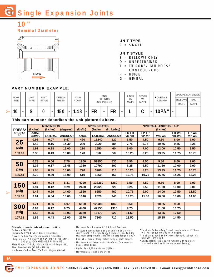
Single Expansion Joints
UNIT TYPES = SINGLE
UNIT STYLEB = BELLOWS ONLYO = UNRESTRAINEDT = TIE RODS/LIMIT RODS/
CONTROL RODSH = HINGEG = GIMBAL
Standard materials of constructionBellows: A240 T321.Liners: A240 T304 (when liner is requested).Covers: Carbon Steel (when cover is requested).Flanges: 25 to 150 psig; 150# ANSI B16.5 RFSO (A105).
300 psig; 300# ANSI B16.5 RFSO (A105).Plate Flanges: 1" thick; 150# ANSI B16.5 drilling (A-36).Pipe: Standard Wt. (A53-B/A106-B).
*Hardware: Carbon Steel (Tie Rods, Hinges, Gimbals).
• Maximum Test Pressure is 1.5 X Rated Pressure.• Pressure Rating is based on a design temperature of
-20˚ F to 600˚ F. If forged flanged ends are specified, themaximum temperature rating for 150 psig design is 500˚F.
• Consult factory for temperature rating of plate flanges.• Maximum Axial Extension is 15% of Axial Compression
Value shown above.• Cycle Life = 3,000 minimum (EJMA).• Movements are non-concurrent.
* To obtain Bellows Only Overall Length, subtract 7" fromWS - WS length and add neck lengths.
* To obtain Banded Bellows Overall Length, subtract 41/2"from WS - WS length.
* Additional length is required for units with hardwareattached to weld ends (please consult factory).
PART NUMBER EXAMPLE:
This part number describes the unit pictured above.
10"
STNEMEVOM)seerged()sehcni()sehcni(
SETARGNIRPS)ni/sbl()ni/sbl( )ged/bl.ni(
"8/1±SHTGNELLLAREVO*)sehcni(
LAIXA.PMOC LARETAL RALUGNA LAIXA LARETAL RALUGNA
RF-RFRV-RV
PF-PFPV-PV SW-SW
SW-RFSW-RV
SW-PFSW-PV
52gisp
69.0 70.0 75.9 024 04231 021 05.6 05.4 05.9 00.8 00.734.1 61.0 03.41 082 0293 08 57.7 57.5 57.01 52.9 52.8
19.1 82.0 00.51 012 0561 06 00.9 00.7 00.21 05.01 05.9
76.301 83.2 34.0 00.51 071 058 05 52.01 52.8 52.31 57.11 57.01
05gisp
87.0 60.0 07.7 0081 05875 035 05.6 05.4 05.9 00.8 00.763.1 71.0 84.31 0301 09701 003 52.8 05.6 05.11 00.01 00.9
59.1 53.0 00.51 027 0073 012 52.01 52.8 52.31 57.11 57.01
44.501 37.2 96.0 00.51 015 0531 051 57.21 57.01 57.51 52.41 52.31
051gisp
45.0 40.0 13.5 0924 063831 0621 05.6 05.4 05.9 00.8 00.749.0 21.0 92.9 0542 02852 027 52.8 05.6 05.11 00.01 00.9
84.1 92.0 06.41 0651 0566 064 57.01 00.9 00.41 05.21 05.11
85.501 10.2 45.0 00.51 0411 0262 043 52.31 05.11 05.61 00.51 00.41
003gisp
17.0 60.0 79.6 0616 083921 0481 05.8 52.01 05.999.0 21.0 57.9 0044 05174 0131 57.9 05.11 57.01
24.1 52.0 39.31 0803 07161 029 05.11 52.31 05.21
13.701 58.1 34.0 00.51 0732 0637 017 05.31 52.51 05.41
MONEZIS
TINUEPYT
TINUELYTS
NGISED.SSERP
LAIXA.PMOC
DNESGNITTIF
)01egaPeeS(
RENIL/W
L'TAM
REVOC/W
L'TAM
LLAREVOHTGNEL
SLAIRETAMLAICEPS
SWOLLEB DNE
L'TAM L'TAM
- - - - - - - -
FMH EXPANSION JOINTS 1-800-359-4673 • (770) 493-1100 • Fax: (770) 493-1410 • E-mail: [email protected]
10 S 0 150 1.48 FR FR L C 103/4"
Nominal Diameter
➢
➢
*
16
Flow

12"Single Expansion Joints
FMH EXPANSION JOINTS 1-800-359-4673 • (770) 493-1100 • Fax: (770) 493-1410 • E-mail: [email protected]
Standard materials of constructionBellows: A240 T321.Liners: A240 T304 (when liner is requested).Covers: Carbon Steel (when cover is requested).Flanges: 25 to 150 psig; 150# ANSI B16.5 RFSO (A105).
300 psig; 300# ANSI B16.5 RFSO (A105).Plate Flanges: 1" thick; 150# ANSI B16.5 drilling (A-36).Pipe: Standard Wt. (A53-B/A106-B).
*Hardware: Carbon Steel (Tie Rods, Hinges, Gimbals).
• Maximum Test Pressure is 1.5 X Rated Pressure.• Pressure Rating is based on a design temperature of
-20˚ F to 600˚ F. If forged flanged ends are specified, themaximum temperature rating for 150 psig design is 500˚F.
• Consult factory for temperature rating of plate flanges.• Maximum Axial Extension is 15% of Axial Compression
Value shown above.• Cycle Life = 3,000 minimum (EJMA).• Movements are non-concurrent.
* To obtain Bellows Only Overall Length, subtract 8" fromWS - WS length and add neck lengths.
* To obtain Banded Bellows Overall Length, subtract 51/2"from WS - WS length.
* Additional length is required for units with hardwareattached to weld ends (please consult factory).
PART NUMBER EXAMPLE:
This part number describes the unit pictured above.
STNEMEVOM)seerged()sehcni()sehcni(
SETARGNIRPS)ni/sbl()ni/sbl( )ged/bl.ni(
"8/1±SHTGNELLLAREVO*)sehcni(
LAIXA.PMOC LARETAL RALUGNA LAIXA LARETAL RALUGNA
RF-RFRV-RV
PF-PFPV-PV SW-SW
SW-RFSW-RV
SW-PFSW-PV
52gisp
41.1 80.0 36.9 035 08361 012 05.7 00.5 00.11 52.9 00.827.1 91.0 44.41 053 0584 041 00.9 05.6 05.21 57.01 05.9
92.2 43.0 00.51 062 0502 011 05.01 00.8 00.41 52.21 00.11
56.541 68.2 25.0 00.51 012 0501 09 00.21 05.9 05.51 57.31 05.21
05gisp
40.1 80.0 27.8 0831 03134 065 05.7 00.5 00.11 52.9 00.838.1 32.0 00.51 097 0508 023 57.9 52.7 52.31 05.11 52.01
16.2 84.0 00.51 055 0672 032 00.21 05.9 05.51 57.31 05.21
66.741 31.3 86.0 00.51 064 0061 091 05.31 00.11 00.71 52.51 00.41
051gisp
85.0 40.0 88.4 0246 017102 0462 05.7 00.5 00.11 52.9 00.871.1 71.0 57.9 0123 01252 0231 05.01 00.8 00.41 52.21 00.11
57.1 83.0 36.41 0412 0747 088 05.31 00.11 00.71 52.51 00.41
00.841 43.2 86.0 00.51 0161 0513 066 05.61 00.41 00.02 52.81 00.71
003gisp
86.0 60.0 07.5 06511 026332 0874 05.9 57.11 57.0132.1 02.0 52.01 0246 06004 0562 05.21 57.41 57.31
87.1 24.0 18.41 0444 09231 0481 05.51 57.71 57.61
78.841 91.2 46.0 00.51 0163 0317 0941 57.71 00.02 00.91
MONEZIS
TINUEPYT
TINUELYTS
NGISED.SSERP
LAIXA.PMOC
DNESGNITTIF
)01egaPeeS(
RENIL/W
L'TAM
REVOC/W
L'TAM
LLAREVOHTGNEL
SLAIRETAMLAICEPS
SWOLLEB DNE
L'TAM L'TAM
- - - - - - - -12 S T 150 1.75 WS WS 22"
Nominal Diameter
UNIT TYPES = SINGLE
UNIT STYLEB = BELLOWS ONLYO = UNRESTRAINEDT = TIE RODS/LIMIT RODS/
CONTROL RODSH = HINGEG = GIMBAL
➢
➢
*
17

Single Expansion Joints
UNIT TYPES = SINGLE
UNIT STYLEB = BELLOWS ONLYO = UNRESTRAINEDT = TIE RODS/LIMIT RODS/
CONTROL RODSH = HINGEG = GIMBAL
Standard materials of constructionBellows: A240 T321.Liners: A240 T304 (when liner is requested).Covers: Carbon Steel (when cover is requested).Flanges: 25 to 150 psig; 150# ANSI B16.5 RFSO (A105).
300 psig; 300# ANSI B16.5 RFSO (A105).Plate Flanges: 1" thick; 150# ANSI B16.5 drilling (A-36).Pipe: Standard Wt. (A53-B/A106-B).
*Hardware: Carbon Steel (Tie Rods, Hinges, Gimbals).
• Maximum Test Pressure is 1.5 X Rated Pressure.• Pressure Rating is based on a design temperature of
-20˚ F to 600˚ F. If forged flanged ends are specified, themaximum temperature rating for 150 psig design is 500˚F.
• Consult factory for temperature rating of plate flanges.• Maximum Axial Extension is 15% of Axial Compression
Value shown above.• Cycle Life = 3,000 minimum (EJMA).• Movements are non-concurrent.
* To obtain Bellows Only Overall Length, subtract 8" fromWS - WS length and add neck lengths.
* To obtain Banded Bellows Overall Length, subtract 51/2"from WS - WS length.
* Additional length is required for units with hardwareattached to weld ends (please consult factory).
PART NUMBER EXAMPLE:
This part number describes the unit pictured above.
14"
STNEMEVOM)seerged()sehcni()sehcni(
SETARGNIRPS)ni/sbl()ni/sbl( )ged/bl.ni(
"8/1±SHTGNELLLAREVO*)sehcni(
LAIXA.PMOC LARETAL RALUGNA LAIXA LARETAL RALUGNA
RF-RFRV-RV
PF-PFPV-PV SW-SW
SW-RFSW-RV
SW-PFSW-PV
52gisp
41.1 80.0 67.8 0711 09234 075 05.7 00.5 00.11 52.9 00.882.2 13.0 00.51 085 0145 082 05.01 00.8 00.41 52.21 00.11
24.3 96.0 00.51 093 0061 091 05.31 00.11 00.71 52.51 00.41
35.471 82.4 80.1 00.51 013 028 051 57.51 52.31 52.91 05.71 52.61
05gisp
30.1 70.0 29.7 0051 01165 037 05.7 00.5 00.11 52.9 00.818.1 12.0 58.31 068 07401 024 57.9 52.7 52.31 05.11 52.01
85.2 34.0 00.51 006 0953 092 00.21 05.9 05.51 57.31 05.21
18.571 01.3 26.0 00.51 005 0802 042 05.31 00.11 00.71 52.51 00.41
051gisp
06.0 40.0 16.4 0986 073912 0733 57.7 52.5 52.11 05.9 52.812.1 71.0 22.9 0443 02472 0961 00.11 05.8 05.41 57.21 05.11
18.1 93.0 38.31 0032 0218 0211 52.41 57.11 57.71 00.61 57.41
91.671 14.2 07.0 00.51 0271 0343 048 05.71 00.51 00.12 52.91 00.81
003gisp
86.0 60.0 91.5 06621 094403 0326 57.9 57.11 57.0122.1 81.0 43.9 0307 01225 0643 57.21 57.41 57.31
36.1 33.0 54.21 0725 03022 0952 00.51 00.71 00.61
31.771 71.2 85.0 00.51 0693 0929 0591 00.81 00.02 00.91
MONEZIS
TINUEPYT
TINUELYTS
NGISED.SSERP
LAIXA.PMOC
DNESGNITTIF
)01egaPeeS(
RENIL/W
L'TAM
REVOC/W
L'TAM
LLAREVOHTGNEL
SLAIRETAMLAICEPS
SWOLLEB DNE
L'TAM L'TAM
- - - - - - - -
FMH EXPANSION JOINTS 1-800-359-4673 • (770) 493-1100 • Fax: (770) 493-1410 • E-mail: [email protected]
14 S 0 300 1.22 FR WS L2 133/4" B2 E2
Nominal Diameter
➢
➢
*
18
Flow

16"Single Expansion Joints
FMH EXPANSION JOINTS 1-800-359-4673 • (770) 493-1100 • Fax: (770) 493-1410 • E-mail: [email protected]
Standard materials of constructionBellows: A240 T321.Liners: A240 T304 (when liner is requested).Covers: Carbon Steel (when cover is requested).Flanges: 25 to 150 psig; 150# ANSI B16.5 RFSO (A105).
300 psig; 300# ANSI B16.5 RFSO (A105).Plate Flanges: 1" thick; 150# ANSI B16.5 drilling (A-36).Pipe: Standard Wt. (A53-B/A106-B).
*Hardware: Carbon Steel (Tie Rods, Hinges, Gimbals).
• Maximum Test Pressure is 1.5 X Rated Pressure.• Pressure Rating is based on a design temperature of
-20˚ F to 600˚ F. If forged flanged ends are specified, themaximum temperature rating for 150 psig design is 500˚F.
• Consult factory for temperature rating of plate flanges.• Maximum Axial Extension is 15% of Axial Compression
Value shown above.• Cycle Life = 3,000 minimum (EJMA).• Movements are non-concurrent.
* To obtain Bellows Only Overall Length, subtract 8" fromWS - WS length and add neck lengths.
* To obtain Banded Bellows Overall Length, subtract 51/2"from WS - WS length.
* Additional length is required for units with hardwareattached to weld ends (please consult factory).
PART NUMBER EXAMPLE:
This part number describes the unit pictured above.
STNEMEVOM)seerged()sehcni()sehcni(
SETARGNIRPS)ni/sbl()ni/sbl( )ged/bl.ni(
"8/1±SHTGNELLLAREVO*)sehcni(
LAIXA.PMOC LARETAL RALUGNA LAIXA LARETAL RALUGNA
RF-RFRV-RV
PF-PFPV-PV SW-SW
SW-RFSW-RV
SW-PFSW-PV
52gisp
33.1 90.0 59.8 019 03223 075 05.8 05.5 05.11 00.01 05.833.2 82.0 00.51 025 0106 033 52.11 52.8 52.41 57.21 52.11
33.3 75.0 00.51 063 0602 032 57.31 57.01 57.61 52.51 57.31
48.722 99.3 28.0 00.51 003 0911 091 05.51 05.21 05.81 00.71 05.51
05gisp
11.1 80.0 34.7 0832 02658 0351 05.8 05.5 05.11 00.01 05.859.1 32.0 10.31 0631 08951 078 52.11 52.8 52.41 57.21 52.11
87.2 74.0 00.51 059 0845 016 57.31 57.01 57.61 52.51 57.31
91.132 26.3 08.0 00.51 037 0942 074 05.61 05.31 05.91 00.81 05.61
051gisp
30.1 70.0 58.6 0315 096581 0133 05.8 05.5 05.11 00.01 05.808.1 12.0 99.11 0392 05643 0981 52.11 52.8 52.41 57.21 52.11
75.2 44.0 00.51 0502 08811 0231 57.31 57.01 57.61 52.51 57.31
60.232 43.3 47.0 00.51 0851 0145 0201 05.61 05.31 05.91 00.81 05.61
003gisp
69.0 80.0 24.6 0128 084091 0035 00.11 05.21 57.1153.1 61.0 89.8 0785 02496 0973 57.21 52.41 05.31
39.1 33.0 38.21 0114 01832 0562 52.51 57.61 00.61
94.232 05.2 55.0 00.51 0613 04801 0402 00.81 05.91 57.81
MONEZIS
TINUEPYT
TINUELYTS
NGISED.SSERP
LAIXA.PMOC
DNESGNITTIF
)01egaPeeS(
RENIL/W
L'TAM
REVOC/W
L'TAM
LLAREVOHTGNEL
SLAIRETAMLAICEPS
SWOLLEB DNE
L'TAM L'TAM
- - - - - - - -16 S B 025 2.33 75/8"
Nominal Diameter
UNIT TYPES = SINGLE
UNIT STYLEB = BELLOWS ONLYO = UNRESTRAINEDT = TIE RODS/LIMIT RODS/
CONTROL RODSH = HINGEG = GIMBAL
➢
➢
*
19

Single Expansion Joints
UNIT TYPES = SINGLE
UNIT STYLEB = BELLOWS ONLYO = UNRESTRAINEDT = TIE RODS/LIMIT RODS/
CONTROL RODSH = HINGEG = GIMBAL
Standard materials of constructionBellows: A240 T321.Liners: A240 T304 (when liner is requested).Covers: Carbon Steel (when cover is requested).Flanges: 25 to 150 psig; 150# ANSI B16.5 RFSO (A105).
300 psig; 300# ANSI B16.5 RFSO (A105).Plate Flanges: 11/16" thick; 150# ANSI B16.5 drilling (A-36).Pipe: Standard Wt. (A53-B/A106-B).
*Hardware: Carbon Steel (Tie Rods, Hinges, Gimbals).
• Maximum Test Pressure is 1.5 X Rated Pressure.• Pressure Rating is based on a design temperature of
-20˚ F to 600˚ F. If forged flanged ends are specified, themaximum temperature rating for 150 psig design is 500˚F.
• Consult factory for temperature rating of plate flanges.• Maximum Axial Extension is 15% of Axial Compression
Value shown above.• Cycle Life = 3,000 minimum (EJMA).• Movements are non-concurrent.
* To obtain Bellows Only Overall Length, subtract 10"from WS - WS length and add neck lengths.
* To obtain Banded Bellows Overall Length, subtract 71/2"from WS - WS length.
* Additional length is required for units with hardwareattached to weld ends (please consult factory).
PART NUMBER EXAMPLE:
This part number describes the unit pictured above.
18"
STNEMEVOM)seerged()sehcni()sehcni(
SETARGNIRPS)ni/sbl()ni/sbl( )ged/bl.ni(
"8/1±SHTGNELLLAREVO*)sehcni(
LAIXA.PMOC LARETAL RALUGNA LAIXA LARETAL RALUGNA
RF-RFRV-RV
PF-PFPV-PV SW-SW
SW-RFSW-RV
SW-PFSW-PV
52gisp
33.1 80.0 10.8 0001 04444 097 00.9 57.5 05.31 52.11 05.933.2 52.0 20.41 075 0928 054 05.11 05.8 52.61 00.41 52.21
33.3 15.0 00.51 004 0482 023 52.41 00.11 57.81 05.61 57.41
94.482 23.4 68.0 00.51 013 0921 042 57.61 57.31 05.12 52.91 05.71
05gisp
01.1 70.0 06.6 0662 075911 0312 00.9 57.5 05.31 52.11 05.939.1 12.0 45.11 0251 01322 0221 05.11 05.8 52.61 00.41 52.21
67.2 24.0 00.51 0601 0567 058 52.41 00.11 57.81 05.61 52.41
32.882 85.3 17.0 00.51 028 0843 066 57.61 57.31 05.12 52.91 05.71
051gisp
20.1 60.0 90.6 0575 002952 0264 00.9 00.6 05.31 52.11 05.997.1 91.0 76.01 0923 06384 0462 05.11 57.8 52.61 00.41 52.21
55.2 93.0 00.51 0032 09561 0581 52.41 52.11 57.81 05.61 57.41
02.982 60.3 65.0 00.51 0291 0069 0451 00.61 00.31 05.02 52.81 05.61
003gisp
69.0 70.0 07.5 0129 001662 0147 05.11 05.41 00.3143.1 41.0 89.7 0856 08969 0925 52.31 52.61 57.41
19.1 92.0 04.11 0064 06233 0073 57.51 57.81 52.71
86.982 84.2 94.0 28.41 0453 04151 0582 05.81 05.12 00.02
MONEZIS
TINUEPYT
TINUELYTS
NGISED.SSERP
LAIXA.PMOC
DNESGNITTIF
)01egaPeeS(
RENIL/W
L'TAM
REVOC/W
L'TAM
LLAREVOHTGNEL
SLAIRETAMLAICEPS
SWOLLEB DNE
L'TAM L'TAM
- - - - - - - -
FMH EXPANSION JOINTS 1-800-359-4673 • (770) 493-1100 • Fax: (770) 493-1410 • E-mail: [email protected]
18 S 0 150 1.79 WS WS L4 C 161/4" B4
Nominal Diameter
➢
➢
*
20
Flow

21
*
20"Single Expansion Joints
FMH EXPANSION JOINTS 1-800-359-4673 • (770) 493-1100 • Fax: (770) 493-1410 • E-mail: [email protected]
Standard materials of constructionBellows: A240 T321.Liners: A240 T304 (when liner is requested).Covers: Carbon Steel (when cover is requested).Flanges: 25 to 150 psig; 150# ANSI B16.5 RFSO (A105).
300 psig; 300# ANSI B16.5 RFSO (A105).Plate Flanges: 11/8" thick; 150# ANSI B16.5 drilling (A-36).Pipe: Standard Wt. (A53-B/A106-B).
*Hardware: Carbon Steel (Tie Rods, Hinges, Gimbals).
• Maximum Test Pressure is 1.5 X Rated Pressure.• Pressure Rating is based on a design temperature of
-20˚ F to 600˚ F. If forged flanged ends are specified, themaximum temperature rating for 150 psig design is 500˚F.
• Consult factory for temperature rating of plate flanges.• Maximum Axial Extension is 15% of Axial Compression
Value shown above.• Cycle Life = 3,000 minimum (EJMA).• Movements are non-concurrent.
* To obtain Bellows Only Overall Length, subtract 10"from WS - WS length and add neck lengths.
* To obtain Banded Bellows Overall Length, subtract 71/2"from WS - WS length.
* Additional length is required for units with hardwareattached to weld ends (please consult factory).
PART NUMBER EXAMPLE:
This part number describes the unit pictured above.
STNEMEVOM)seerged()sehcni()sehcni(
SETARGNIRPS)ni/sbl()ni/sbl( )ged/bl.ni(
"8/1±SHTGNELLLAREVO*)sehcni(
LAIXA.PMOC LARETAL RALUGNA LAIXA LARETAL RALUGNA
RF-RFRV-RV
PF-PFPV-PV SW-SW
SW-RFSW-RV
SW-PFSW-PV
52gisp
25.1 01.0 82.8 0112 09678 0402 57.9 52.6 00.41 00.21 52.0166.2 03.0 94.41 0121 06361 0711 57.21 52.9 00.71 00.51 52.31
08.3 06.0 00.51 058 0165 028 57.51 52.21 00.02 00.81 52.61
86.743 49.4 20.1 00.51 056 0552 036 57.81 52.51 00.32 00.12 52.91
05gisp
73.1 90.0 04.7 0412 05909 0212 57.9 52.6 00.41 00.21 52.0104.2 62.0 49.21 0221 07961 0121 57.21 52.9 00.71 00.51 52.31
34.3 45.0 00.51 068 0285 058 57.51 52.21 00.02 00.81 52.61
37.553 21.4 77.0 00.51 017 0733 017 57.71 52.41 00.22 00.02 52.81
051gisp
62.1 80.0 08.6 0954 025591 0554 57.9 52.6 00.41 00.21 52.0112.2 42.0 09.11 0262 08463 0062 57.21 52.9 00.71 00.51 52.31
61.3 94.0 00.51 0481 01521 0281 57.51 52.21 00.02 00.81 52.61
08.653 97.3 17.0 00.51 0351 0427 0251 57.71 52.41 00.22 00.02 52.81
003gisp
69.0 80.0 71.5 01741 003204 03641 05.21 00.51 57.3153.1 51.0 42.7 01501 016641 05401 05.41 00.71 57.51
39.1 03.0 53.01 0537 09205 0137 05.71 00.02 57.81
00.853 13.2 34.0 24.21 0316 00192 0906 05.91 00.22 57.02
MONEZIS
TINUEPYT
TINUELYTS
NGISED.SSERP
LAIXA.PMOC
DNESGNITTIF
)01egaPeeS(
RENIL/W
L'TAM
REVOC/W
L'TAM
LLAREVOHTGNEL
SLAIRETAMLAICEPS
SWOLLEB DNE
L'TAM L'TAM
- - - - - - - -20 S T 150 2.21 FR FR 123/4"
Nominal Diameter
UNIT TYPES = SINGLE
UNIT STYLEB = BELLOWS ONLYO = UNRESTRAINEDT = TIE RODS/LIMIT RODS/
CONTROL RODSH = HINGEG = GIMBAL
➢
➢

Single Expansion Joints
UNIT TYPES = SINGLE
UNIT STYLEB = BELLOWS ONLYO = UNRESTRAINEDT = TIE RODS/LIMIT RODS/
CONTROL RODSH = HINGEG = GIMBAL
Standard materials of constructionBellows: A240 T321.Liners: A240 T304 (when liner is requested).Covers: Carbon Steel (when cover is requested).Flanges: 25 to 150 psig; 150# ANSI B16.5 RFSO (A105).
300 psig; 300# ANSI B16.5 RFSO (A105).Plate Flanges: 13/16" thick. 150# ANSI B16.5 drilling (A-36).Pipe: 25 to 150 psig; Std. Wt. pipe (A53-B/A106-B).
300 psig; 0.5" wall (A106-B/A516-70).*Hardware: Carbon Steel (Tie Rods, Hinges, Gimbals).
• Maximum Test Pressure is 1.5 X Rated Pressure.• Pressure Rating is based on a design temperature of
-20˚ F to 600˚ F. If forged flanged ends are specified, themaximum temperature rating for 150 psig design is 500˚F.
• Consult factory for temperature rating of plate flanges.• Maximum Axial Extension is 15% of Axial Compression
Value shown above.• Cycle Life = 3,000 minimum (EJMA).• Movements are non-concurrent.
* To obtain Bellows Only Overall Length, subtract 10"from WS - WS length and add neck lengths.
* To obtain Banded Bellows Overall Length, subtract 71/2"from WS - WS length.
* Additional length is required for units with hardwareattached to weld ends (please consult factory).
PART NUMBER EXAMPLE:
This part number describes the unit pictured above.
22"
STNEMEVOM)seerged()sehcni()sehcni(
SETARGNIRPS)ni/sbl()ni/sbl( )ged/bl.ni(
"8/1±SHTGNELLLAREVO*)sehcni(
LAIXA.PMOC LARETAL RALUGNA LAIXA LARETAL RALUGNA
RF-RFRV-RV
PF-PFPV-PV SW-SW
SW-RFSW-RV
SW-PFSW-PV
52gisp
25.1 90.0 25.7 0561 09728 0391 52.01 05.6 00.41 52.21 52.0166.2 72.0 61.31 049 05451 0011 52.31 05.9 00.71 52.51 52.31
08.3 55.0 00.51 0601 0658 0421 52.61 05.21 00.02 52.81 52.61
64.124 49.4 29.0 00.51 015 0142 095 52.91 05.51 00.32 52.12 52.91
05gisp
63.1 80.0 17.6 0532 032911 0772 52.01 05.6 00.41 52.21 52.0193.2 42.0 57.11 0431 05222 0951 52.31 05.9 00.71 52.51 52.31
14.3 94.0 00.51 049 0367 0111 52.61 05.21 00.02 52.81 52.61
37.524 90.4 07.0 00.51 087 0244 029 52.81 05.41 00.22 52.02 52.81
051gisp
62.1 70.0 71.6 0305 052652 0695 52.01 05.6 00.41 52.21 52.0102.2 22.0 08.01 0782 01874 0143 52.31 05.9 00.71 52.51 52.31
41.3 54.0 00.51 0102 00461 0932 52.61 05.21 00.02 52.81 52.61
09.624 77.3 56.0 00.51 0861 0949 0991 52.81 05.41 00.22 52.02 52.81
003gisp
69.0 70.0 07.4 04161 019725 00291 00.31 00.51 00.4143.1 31.0 85.6 03511 093291 01731 00.51 00.71 00.61
29.1 72.0 04.9 0708 09956 0069 00.81 00.02 00.91
22.824 03.2 93.0 82.11 0276 09183 0008 00.02 00.22 00.12
MONEZIS
TINUEPYT
TINUELYTS
NGISED.SSERP
LAIXA.PMOC
DNESGNITTIF
)01egaPeeS(
RENIL/W
L'TAM
REVOC/W
L'TAM
LLAREVOHTGNEL
SLAIRETAMLAICEPS
SWOLLEB DNE
L'TAM L'TAM
- - - - - - - -
FMH EXPANSION JOINTS 1-800-359-4673 • (770) 493-1100 • Fax: (770) 493-1410 • E-mail: [email protected]
22 S O 150 2.20 FP FP 91/2"
Nominal Diameter
➢
➢
*
22

23
*
24"Single Expansion Joints
FMH EXPANSION JOINTS 1-800-359-4673 • (770) 493-1100 • Fax: (770) 493-1410 • E-mail: [email protected]
Standard materials of constructionBellows: A240 T321.Liners: A240 T304 (when liner is requested).Covers: Carbon Steel (when cover is requested).Flanges: 25 to 150 psig; 150# ANSI B16.5 RFSO (A105).
300 psig; 300# ANSI B16.5 RFSO (A105).Plate Flanges: 11/4" thick. 150# ANSI B16.5 drilling (A-36).Pipe: 25 to 150 psig; Std. Wt. pipe (A53-B/A106-B).
300 psig; 0.5" wall (A106-B/A516-70).*Hardware: Carbon Steel (Tie Rods, Hinges, Gimbals).
• Maximum Test Pressure is 1.5 X Rated Pressure.• Pressure Rating is based on a design temperature of
-20˚ F to 600˚ F. If forged flanged ends are specified, themaximum temperature rating for 150 psig design is 500˚F.
• Consult factory for temperature rating of plate flanges.• Maximum Axial Extension is 15% of Axial Compression
Value shown above.• Cycle Life = 3,000 minimum (EJMA).• Movements are non-concurrent.
* To obtain Bellows Only Overall Length, subtract 10"from WS - WS length and add neck lengths.
* To obtain Banded Bellows Overall Length, subtract 71/2"from WS - WS length.
* Additional length is required for units with hardwareattached to weld ends (please consult factory).
PART NUMBER EXAMPLE:
This part number describes the unit pictured above.
STNEMEVOM)seerged()sehcni()sehcni(
SETARGNIRPS)ni/sbl()ni/sbl( )ged/bl.ni(
"8/1±SHTGNELLLAREVO*)sehcni(
LAIXA.PMOC LARETAL RALUGNA LAIXA LARETAL RALUGNA
RF-RFRV-RV
PF-PFPV-PV SW-SW
SW-RFSW-RV
SW-PFSW-PV
52gisp
25.1 80.0 98.6 0231 02497 0581 05.01 05.6 00.41 52.21 52.0166.2 52.0 50.21 067 02841 0601 05.31 05.9 00.71 52.51 52.31
08.3 05.0 00.51 035 0805 047 05.61 05.21 00.02 52.81 52.61
33.205 49.4 58.0 00.51 055 0113 067 05.91 05.51 00.32 52.12 52.91
05gisp
63.1 70.0 41.6 0552 018251 0653 05.01 05.6 00.41 52.21 52.0173.2 22.0 57.01 0641 01582 0302 05.31 05.9 00.71 52.51 52.31
93.3 54.0 00.51 0201 0879 0241 05.61 05.21 00.02 52.81 52.61
10.205 70.4 46.0 00.51 058 0665 0911 05.81 05.41 00.22 52.02 52.81
051gisp
52.1 70.0 56.5 0745 033823 0467 05.01 05.6 00.41 52.21 52.0181.2 02.0 88.9 0213 06216 0734 05.31 05.9 00.71 52.51 52.31
21.3 14.0 11.41 0912 01012 0603 05.61 05.21 00.02 52.81 52.61
82.305 47.3 95.0 00.51 0281 06121 0552 05.81 05.41 00.22 52.02 52.81
003gisp
59.0 60.0 13.4 06571 061776 02642 05.31 00.51 52.4133.1 21.0 30.6 04521 087642 09571 05.51 00.71 52.61
19.1 52.0 16.8 0878 04648 01321 05.81 00.02 52.91
27.405 92.2 63.0 33.01 0237 08984 06201 05.02 00.22 52.12
MONEZIS
TINUEPYT
TINUELYTS
NGISED.SSERP
LAIXA.PMOC
DNESGNITTIF
)01egaPeeS(
RENIL/W
L'TAM
REVOC/W
L'TAM
LLAREVOHTGNEL
SLAIRETAMLAICEPS
SWOLLEB DNE
L'TAM L'TAM
- - - - - - - -24 S O 150 2.18 VR VR 131/2"
Nominal Diameter
UNIT TYPES = SINGLE
UNIT STYLEB = BELLOWS ONLYO = UNRESTRAINEDT = TIE RODS/LIMIT RODS/
CONTROL RODSH = HINGEG = GIMBAL
➢
➢

Single Expansion Joints
UNIT TYPES = SINGLE
UNIT STYLEB = BELLOWS ONLYO = UNRESTRAINEDT = TIE RODS/LIMIT RODS/
CONTROL RODSH = HINGEG = GIMBAL
Standard materials of constructionBellows: A240 T321.Liners: A240 T304 (when liner is requested).Covers: Carbon Steel (when cover is requested).Flanges: 25 & 50 psig; 125# LW F.F.S.O. (A105).
Customer to advise flange specification for 150 psig design.
Plate Flanges: Are available upon request and withdimensional information provided by customer.
Pipe: 25 to 150 psig; Std. Wt.(3/8" wall)(A53-B/A106-B/A-36/A516-70).
*Hardware: Carbon Steel (Tie Rods, Hinges, Gimbals).
• Maximum Test Pressure is 1.5 X Rated Pressure.• Pressure Rating is based on a design temperature of
-20˚ F to 600˚ F. If flanged ends are required, please consult factory for maximum temperature rating.
• Maximum Axial Extension is 15% of Axial CompressionValue shown above.
• Cycle Life = 3,000 minimum (EJMA).• Movements are non-concurrent.• 300 psig designs can be provided upon request.
* To obtain Bellows Only Overall Length, subtract 12"from WS - WS length and add neck lengths.
* To obtain Banded Bellows Overall Length, subtract 91/2"from WS - WS length.
* Additional length is required for units with hardwareattached to weld ends (please consult factory).
PART NUMBER EXAMPLE:
This part number describes the unit pictured above.
26"
STNEMEVOM)seerged()sehcni()sehcni(
SETARGNIRPS)ged/bl.ni()ni/sbl()ni/sbl(
"8/1±SHTGNELLLAREVO*)sehcni(
LAIXA.PMOC LARETAL RALUGNA LAIXA LARETAL RALUGNA
RF-RFRV-RV
PF-PFPV-PV SW-SW
SW-RFSW-RV
SW-PFSW-PV
52gisp
25.1 70.0 83.6 0642 015171 0993 05.7 00.61 57.11
66.2 32.0 71.11 0041 00023 0822 05.01 00.91 57.41
08.3 64.0 00.51 089 08901 0061 05.31 00.22 57.71
72.585 49.4 87.0 00.51 067 0005 0321 05.61 00.52 57.02
05gisp
53.1 70.0 66.5 0572 031291 0744 05.7 00.61 57.11
63.2 02.0 09.9 0751 05853 0552 05.01 00.91 57.41
73.3 14.0 51.41 0011 00321 0971 05.31 00.22 57.71
85.485 40.4 95.0 00.51 029 0217 0941 05.51 00.42 57.91
051gisp
42.1 60.0 02.5 0095 027214 0069 00.61
71.2 91.0 11.9 0733 01077 0945 00.91
01.3 83.0 10.31 0632 01462 0483 00.22
59.585 27.3 45.0 00.51 0791 09251 0023 00.42
MONEZIS
TINUEPYT
TINUELYTS
NGISED.SSERP
LAIXA.PMOC
DNESGNITTIF
)01egaPeeS(
RENIL/W
L'TAM
REVOC/W
L'TAM
LLAREVOHTGNEL
SLAIRETAMLAICEPS
SWOLLEB DNE
L'TAM L'TAM
- - - - - - - -
FMH EXPANSION JOINTS 1-800-359-4673 • (770) 493-1100 • Fax: (770) 493-1410 • E-mail: [email protected]
26 S O 050 2.36 FR FR 101/2"
Nominal Diameter
➢
➢
*
24
Customer
to specify
Plate Flange
Dimensions
Customer
to specify
Plate Flange
Dimensions
Customer
to specify
Plate Flange
Dimensions
Customer
to specify
Plate Flange
Dimensions
Customer
to advise
Flange
Specification
Customer
to specify
Plate Flange
Dimensions
Customer
to advise
Flange
Specification
Customer
to specify
Plate Flange
Dimensions

28"Single Expansion Joints
FMH EXPANSION JOINTS 1-800-359-4673 • (770) 493-1100 • Fax: (770) 493-1410 • E-mail: [email protected]
Standard materials of constructionBellows: A240 T321.Liners: A240 T304 (when liner is requested).Covers: Carbon Steel (when cover is requested).Flanges: 25 & 50 psig; 125# LW F.F.S.O. (A105).
Customer to advise flange specification for 150 psig design.
Plate Flanges: Are available upon request and withdimensional information provided by customer.
Pipe: 25 to 150 psig; Std. Wt.(3/8" wall)(A53-B/A106-B/A-36/A516-70).
*Hardware: Carbon Steel (Tie Rods, Hinges, Gimbals).
• Maximum Test Pressure is 1.5 X Rated Pressure.• Pressure Rating is based on a design temperature of
-20˚ F to 600˚ F. If flanged ends are required, please consult factory for maximum temperature rating.
• Maximum Axial Extension is 15% of Axial CompressionValue shown above.
• Cycle Life = 3,000 minimum (EJMA).• Movements are non-concurrent.• 300 psig designs can be provided upon request.
* To obtain Bellows Only Overall Length, subtract 12"from WS - WS length and add neck lengths.
* To obtain Banded Bellows Overall Length, subtract 91/2"from WS - WS length.
* Additional length is required for units with hardwareattached to weld ends (please consult factory).
PART NUMBER EXAMPLE:
This part number describes the unit pictured above.
STNEMEVOM)seerged()sehcni()sehcni(
SETARGNIRPS)ged/bl.ni()ni/sbl()ni/sbl(
"8/1±SHTGNELLLAREVO*)sehcni(
LAIXA.PMOC LARETAL RALUGNA LAIXA LARETAL RALUGNA
RF-RFRV-RV
PF-PFPV-PV SW-SW
SW-RFSW-RV
SW-PFSW-PV
52gisp
25.1 70.0 59.5 0362 049112 0394 05.7 00.61 57.11
66.2 12.0 04.01 0051 05593 0282 05.01 00.91 57.41
08.3 34.0 68.41 0501 06531 0791 05.31 00.22 57.71
71.476 49.4 37.0 00.51 018 0716 0251 05.61 00.52 57.02
05gisp
43.1 60.0 52.5 0692 046732 0355 05.7 00.61 57.11
53.2 91.0 81.9 0961 04344 0613 05.01 00.91 57.41
53.3 83.0 21.31 0811 01251 0122 05.31 00.22 57.71
34.376 20.4 55.0 00.51 099 0088 0481 05.51 00.42 57.91
051gisp
32.1 60.0 28.4 0436 093015 08811 57.71
61.2 71.0 44.8 0263 03259 0976 57.02
90.3 53.0 60.21 0352 06623 0574 57.32
09.476 07.3 15.0 74.41 0112 00981 0693 57.52
MONEZIS
TINUEPYT
TINUELYTS
NGISED.SSERP
LAIXA.PMOC
DNESGNITTIF
)01egaPeeS(
RENIL/W
L'TAM
REVOC/W
L'TAM
LLAREVOHTGNEL
SLAIRETAMLAICEPS
SWOLLEB DNE
L'TAM L'TAM
- - - - - - - -28 S O 050 2.35 WS WS L 19" B3
Nominal Diameter
UNIT TYPES = SINGLE
UNIT STYLEB = BELLOWS ONLYO = UNRESTRAINEDT = TIE RODS/LIMIT RODS/
CONTROL RODSH = HINGEG = GIMBAL
➢
➢
*
25
Customer
to specify
Plate Flange
Dimensions
Customer
to specify
Plate Flange
Dimensions
Customer
to specify
Plate Flange
Dimensions
Customer
to specify
Plate Flange
Dimensions
Customer
to advise
Flange
Specification
Customer
to specify
Plate Flange
Dimensions
Customer
to advise
Flange
Specification
Customer
to specify
Plate Flange
Dimensions
Flow

Single Expansion Joints
UNIT TYPES = SINGLE
UNIT STYLEB = BELLOWS ONLYO = UNRESTRAINEDT = TIE RODS/LIMIT RODS/
CONTROL RODSH = HINGEG = GIMBAL
Standard materials of constructionBellows: A240 T321.Liners: A240 T304 (when liner is requested).Covers: Carbon Steel (when cover is requested).Flanges: 25 & 50 psig; 125# LW F.F.S.O. (A105).
Customer to advise flange specification for 150 psig design.
Plate Flanges: Are available upon request and withdimensional information provided by customer.
Pipe: 25 to 150 psig; Std. Wt.(3/8" wall)(A53-B/A106-B/A-36/A516-70).
*Hardware: Carbon Steel (Tie Rods, Hinges, Gimbals).
• Maximum Test Pressure is 1.5 X Rated Pressure.• Pressure Rating is based on a design temperature of
-20˚ F to 600˚ F. If flanged ends are required, please consult factory for maximum temperature rating.
• Maximum Axial Extension is 15% of Axial CompressionValue shown above.
• Cycle Life = 3,000 minimum (EJMA).• Movements are non-concurrent.• 300 psig designs can be provided upon request.
* To obtain Bellows Only Overall Length, subtract 12"from WS - WS length and add neck lengths.
* To obtain Banded Bellows Overall Length, subtract 91/2"from WS - WS length.
* Additional length is required for units with hardwareattached to weld ends (please consult factory).
PART NUMBER EXAMPLE:
This part number describes the unit pictured above.
30"
STNEMEVOM)seerged()sehcni()sehcni(
SETARGNIRPS)ged/bl.ni()ni/sbl()ni/sbl(
"8/1±SHTGNELLLAREVO*)sehcni(
LAIXA.PMOC LARETAL RALUGNA LAIXA LARETAL RALUGNA
RF-RFRV-RV
PF-PFPV-PV SW-SW
SW-RFSW-RV
SW-PFSW-PV
52gisp
25.1 60.0 75.5 0182 032852 0106 05.7 00.61 57.11
66.2 02.0 47.9 0161 08184 0343 05.01 00.91 57.41
08.3 04.0 19.31 0211 03561 0042 05.31 00.22 57.71
72.585 49.4 86.0 00.51 078 0257 0581 05.61 00.52 57.02
05gisp
33.1 60.0 98.4 0613 097982 0476 05.7 00.61 57.11
43.2 71.0 65.8 0181 07045 0583 05.01 00.91 57.41
43.3 63.0 32.21 0621 05581 0072 05.31 00.22 57.71
85.485 00.4 15.0 76.41 0501 03701 0522 05.51 00.42 57.91
051gisp
32.1 50.0 05.4 0776 082226 08441 00.61
51.2 61.0 78.7 0783 011611 0728 00.91
70.3 33.0 42.11 0172 03893 0975 00.22
59.585 96.3 74.0 94.31 0622 05032 0384 00.42
MONEZIS
TINUEPYT
TINUELYTS
NGISED.SSERP
LAIXA.PMOC
DNESGNITTIF
)01egaPeeS(
RENIL/W
L'TAM
REVOC/W
L'TAM
LLAREVOHTGNEL
SLAIRETAMLAICEPS
SWOLLEB DNE
L'TAM L'TAM
- - - - - - - -
FMH EXPANSION JOINTS 1-800-359-4673 • (770) 493-1100 • Fax: (770) 493-1410 • E-mail: [email protected]
30 S O 025 2.66 BB BB 91/2"
Nominal Diameter
➢
➢
*
26
Customer
to specify
Plate Flange
Dimensions
Customer
to specify
Plate Flange
Dimensions
Customer
to specify
Plate Flange
Dimensions
Customer
to specify
Plate Flange
Dimensions
Customer
to advise
Flange
Specification
Customer
to specify
Plate Flange
Dimensions
Customer
to advise
Flange
Specification
Customer
to specify
Plate Flange
Dimensions

32" and 34"Single Expansion Joints
FMH EXPANSION JOINTS 1-800-359-4673 • (770) 493-1100 • Fax: (770) 493-1410 • E-mail: [email protected]
Standard materials of constructionBellows: A240 T321.Liners: A240 T304 (when liner is requested).Covers: Carbon Steel (when cover is requested).Flanges: 25 & 50 psig; 125# LW F.F.S.O. (A105).Plate Flanges: Are available upon request and with
dimensional information provided by customer.Pipe: 25 & 50 psig; Std. Wt.(3/8" wall)
(A53-B/A106-B/A-36/A516-70).Hardware: Carbon Steel (Tie Rods, Hinges, Gimbals).
• Maximum Test Pressure is 1.5 X Rated Pressure.• Pressure Rating is based on a design temperature of
-20˚ F to 600˚ F. If flanged ends are required, please consult factory for maximum temperature rating.
• Maximum Axial Extension is 15% of Axial CompressionValue shown above.
• Cycle Life = 3,000 minimum (EJMA).• Movements are non-concurrent.• 150 and 300 psig designs can be provided upon request
* To obtain Bellows Only Overall Length, subtract 12"from WS - WS length and add neck lengths.
* To obtain Banded Bellows Overall Length, subtract 91/2"from WS - WS length.
* Additional length is required for units with hardwareattached to weld ends (please consult factory).
PART NUMBER EXAMPLE:
This part number describes the unit pictured above.
"23STNEMEVOM
)seerged()sehcni()sehcni(SETARGNIRPS
)ged/bl.ni()ni/sbl()ni/sbl("8/1±SHTGNELLLAREVO*
)sehcni(LAIXA.PMOC LARETAL RALUGNA LAIXA LARETAL RALUGNA
RF-RFRV-RV
PF-PFPV-PV SW-SW
SW-RFSW-RV
SW-PFSW-PV
52gisp
25.1 60.0 32.5 0992 077013 0327 05.7 00.61 57.1166.2 91.0 51.9 0171 09975 0314 05.01 00.91 57.4108.3 83.0 80.31 0021 09891 0982 05.31 00.22 57.71
28.078 49.4 46.0 00.51 029 0509 0322 05.61 00.52 57.02
05gisp
33.1 50.0 85.4 0633 020943 0218 05.7 00.61 57.1133.2 61.0 10.8 0291 02156 0464 05.01 00.91 57.4123.3 33.0 54.11 0431 04322 0523 05.31 00.22 57.71
89.968 99.3 84.0 37.31 0211 03921 0172 05.51 00.42 57.91
"43
52gisp
25.1 60.0 39.4 0713 069963 0168 05.7 00.61 57.1166.2 81.0 46.8 0181 03096 0294 05.01 00.91 57.4108.3 63.0 43.21 0721 08632 0443 05.31 00.22 57.71
75.879 49.4 16.0 00.51 079 08701 0562 05.61 00.52 57.02
05gisp
23.1 50.0 03.4 0653 087514 0869 05.7 00.61 57.1123.2 51.0 35.7 0402 08577 0355 05.01 00.91 57.4113.3 13.0 67.01 0341 01662 0783 05.31 00.22 57.71
86.779 13.4 35.0 99.31 0011 01121 0892 05.61 00.52 57.02
MONEZIS
TINUEPYT
TINUELYTS
NGISED.SSERP
LAIXA.PMOC
DNESGNITTIF
)01egaPeeS(
RENIL/W
L'TAM
REVOC/W
L'TAM
LLAREVOHTGNEL
SLAIRETAMLAICEPS
SWOLLEB DNE
L'TAM L'TAM
- - - - - - - -34 S O 025 2.66 FR WS L4 143/4"
Nominal Diameter
UNIT TYPES = SINGLE
UNIT STYLEB = BELLOWS ONLYO = UNRESTRAINEDT = TIE RODS/LIMIT RODS/
CONTROL RODSH = HINGEG = GIMBAL
➢
➢
*
27
Customer
to specify
Plate Flange
Dimensions
Customer
to specify
Plate Flange
Dimensions
Customer
to specify
Plate Flange
Dimensions
Customer
to specify
Plate Flange
Dimensions
Customer
to specify
Plate Flange
Dimensions
Customer
to specify
Plate Flange
Dimensions
Customer
to specify
Plate Flange
Dimensions
Customer
to specify
Plate Flange
Dimensions
Flow

Single Expansion Joints
UNIT TYPES = SINGLE
UNIT STYLEB = BELLOWS ONLYO = UNRESTRAINEDT = TIE RODS/LIMIT RODS/
CONTROL RODSH = HINGEG = GIMBAL
Standard materials of constructionBellows: A240 T321.Liners: A240 T304 (when liner is requested).Covers: Carbon Steel (when cover is requested).Flanges: 25 & 50 psig; 125# LW F.F.S.O. (A105).Plate Flanges: Are available upon request and with
dimensional information provided by customer.Pipe: 25 & 50 psig; Std. Wt.(3/8" wall)
(A53-B/A106-B/A-36/A516-70).Hardware: Carbon Steel (Tie Rods, Hinges, Gimbals).
• Maximum Test Pressure is 1.5 X Rated Pressure.• Pressure Rating is based on a design temperature of
-20˚ F to 600˚ F. If flanged ends are required, please consult factory for maximum temperature rating.
• Maximum Axial Extension is 15% of Axial CompressionValue shown above.
• Cycle Life = 3,000 minimum (EJMA).• Movements are non-concurrent.• 150 and 300 psig designs can be provided upon request.
* To obtain Bellows Only Overall Length, subtract 12"from WS - WS length and add neck lengths.
* To obtain Banded Bellows Overall Length, subtract 91/2"from WS - WS length.
* Additional length is required for units with hardwareattached to weld ends (please consult factory).
PART NUMBER EXAMPLE:
This part number describes the unit pictured above.
36" and 38"
"63STNEMEVOM
)seerged()sehcni()sehcni(SETARGNIRPS
)ged/bl.ni()ni/sbl()ni/sbl("8/1±SHTGNELLLAREVO*
)sehcni(LAIXA.PMOC LARETAL RALUGNA LAIXA LARETAL RALUGNA
RF-RFRV-RV
PF-PFPV-PV SW-SW
SW-RFSW-RV
SW-PFSW-PV
52gisp
66.1 60.0 90.5 0252 066672 0077 00.8 05.61 52.2159.2 02.0 20.9 0441 04205 0934 52.11 57.91 05.5181.4 14.0 08.21 0101 08471 0803 05.41 00.32 57.81
49.9901 40.5 95.0 00.51 048 03001 0652 57.61 52.52 00.12
05gisp
82.1 50.0 19.3 0165 028156 02171 57.7 52.61 00.2182.2 61.0 79.6 0713 087011 0869 52.11 57.91 05.5142.3 23.0 39.9 0222 06583 0976 05.41 00.32 57.81
74.9901 09.3 64.0 39.11 0581 02122 0565 57.61 52.52 00.12
"83
52gisp
26.1 60.0 96.4 0762 038443 0609 57.7 52.61 00.2159.2 91.0 65.8 0151 08685 0315 52.11 57.91 05.5181.4 93.0 51.21 0601 02402 0953 05.41 00.32 57.81
56.0221 40.5 65.0 46.41 088 02711 0992 57.61 52.52 00.12
05gisp
82.1 50.0 17.3 0985 025067 08991 57.7 52.61 00.2172.2 51.0 06.6 0433 025921 01311 52.11 57.91 05.5132.3 03.0 93.9 0432 09054 0497 05.41 00.32 57.81
51.0221 88.3 44.0 92.11 0591 07852 0166 57.61 52.52 00.12
MONEZIS
TINUEPYT
TINUELYTS
NGISED.SSERP
LAIXA.PMOC
DNESGNITTIF
)01egaPeeS(
RENIL/W
L'TAM
REVOC/W
L'TAM
LLAREVOHTGNEL
SLAIRETAMLAICEPS
SWOLLEB DNE
L'TAM L'TAM
- - - - - - - -
FMH EXPANSION JOINTS 1-800-359-4673 • (770) 493-1100 • Fax: (770) 493-1410 • E-mail: [email protected]
38 S O 050 2.27 WS WS 193/4"
Nominal Diameter
➢
➢
*
28
Customer
to specify
Plate Flange
Dimensions
Customer
to specify
Plate Flange
Dimensions
Customer
to specify
Plate Flange
Dimensions
Customer
to specify
Plate Flange
Dimensions
Customer
to specify
Plate Flange
Dimensions
Customer
to specify
Plate Flange
Dimensions
Customer
to specify
Plate Flange
Dimensions
Customer
to specify
Plate Flange
Dimensions
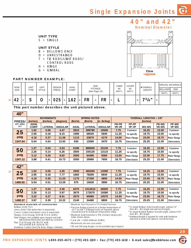
40" and 42"Single Expansion Joints
FMH EXPANSION JOINTS 1-800-359-4673 • (770) 493-1100 • Fax: (770) 493-1410 • E-mail: [email protected]
Standard materials of constructionBellows: A240 T321.Liners: A240 T304 (when liner is requested).Covers: Carbon Steel (when cover is requested).Flanges: 25 & 50 psig; 125# LW F.F.S.O. (A105).Plate Flanges: Are available upon request and with
dimensional information provided by customer.Pipe: 25 & 50 psig; Std. Wt.(3/8" wall)
(A53-B/A106-B/A-36/A516-70).Hardware: Carbon Steel (Tie Rods, Hinges, Gimbals).
• Maximum Test Pressure is 1.5 X Rated Pressure.• Pressure Rating is based on a design temperature of
-20˚ F to 600˚ F. If flanged ends are required, please consult factory for maximum temperature rating.
• Maximum Axial Extension is 15% of Axial CompressionValue shown above.
• Cycle Life = 3,000 minimum (EJMA).• Movements are non-concurrent.• 150 and 300 psig designs can be provided upon request.
* To obtain Bellows Only Overall Length, subtract 12"from WS - WS length and add neck lengths.
* To obtain Banded Bellows Overall Length, subtract 91/2"from WS - WS length.
* Additional length is required for units with hardwareattached to weld ends (please consult factory).
PART NUMBER EXAMPLE:
This part number describes the unit pictured above.
"04STNEMEVOM
)seerged()sehcni()sehcni(SETARGNIRPS
)ged/bl.ni()ni/sbl()ni/sbl("8/1±SHTGNELLLAREVO*
)sehcni(LAIXA.PMOC LARETAL RALUGNA LAIXA LARETAL RALUGNA
RF-RFRV-RV
PF-PFPV-PV SW-SW
SW-RFSW-RV
SW-PFSW-PV
52gisp
26.1 60.0 74.4 0182 087993 00501 57.7 52.61 00.2159.2 81.0 51.8 0951 02086 0495 52.11 57.91 05.5181.4 73.0 65.11 0111 07632 0714 05.41 00.32 57.81
46.7431 40.5 45.0 39.31 039 08531 0743 57.61 52.52 00.12
05gisp
72.1 40.0 35.3 0816 006088 03132 57.7 52.61 00.2162.2 41.0 62.6 0053 021051 01131 52.11 57.91 05.5121.3 52.0 26.8 0052 09346 0639 05.31 00.22 57.71
21.7431 88.3 14.0 37.01 0502 08992 0567 57.61 52.52 00.12
"24
52gisp
26.1 50.0 62.4 0492 062064 09021 57.7 52.61 00.2159.2 81.0 77.7 0661 09287 0486 52.11 57.91 05.5181.4 53.0 30.11 0711 05272 0084 05.41 00.32 57.81
29.0841 40.5 15.0 92.31 079 03651 0993 57.61 52.52 00.12
05gisp
72.1 40.0 63.3 0746 0162101 00662 57.7 52.61 00.2162.2 31.0 79.5 0763 076271 08051 52.11 57.91 05.5122.3 72.0 15.8 0752 08006 07501 05.41 00.32 57.81
73.0841 78.3 93.0 22.01 0412 08443 0088 57.61 52.52 00.12
MONEZIS
TINUEPYT
TINUELYTS
NGISED.SSERP
LAIXA.PMOC
DNESGNITTIF
)01egaPeeS(
RENIL/W
L'TAM
REVOC/W
L'TAM
LLAREVOHTGNEL
SLAIRETAMLAICEPS
SWOLLEB DNE
L'TAM L'TAM
- - - - - - - -42 S O 025 1.62 FR FR L 73/4"
Nominal Diameter
UNIT TYPES = SINGLE
UNIT STYLEB = BELLOWS ONLYO = UNRESTRAINEDT = TIE RODS/LIMIT RODS/
CONTROL RODSH = HINGEG = GIMBAL
➢
➢
*
29
Customer
to specify
Plate Flange
Dimensions
Customer
to specify
Plate Flange
Dimensions
Customer
to specify
Plate Flange
Dimensions
Customer
to specify
Plate Flange
Dimensions
Customer
to specify
Plate Flange
Dimensions
Customer
to specify
Plate Flange
Dimensions
Customer
to specify
Plate Flange
Dimensions
Customer
to specify
Plate Flange
Dimensions
Flow

Single Expansion Joints
UNIT TYPES = SINGLE
UNIT STYLEB = BELLOWS ONLYO = UNRESTRAINEDT = TIE RODS/LIMIT RODS/
CONTROL RODSH = HINGEG = GIMBAL
Standard materials of constructionBellows: A240 T321.Liners: A240 T304 (when liner is requested).Covers: Carbon Steel (when cover is requested).Flanges: 25 & 50 psig; 125# LW F.F.S.O. (A105).Plate Flanges: Are available upon request and with
dimensional information provided by customer.Pipe: 25 & 50 psig; Std. Wt.(3/8" wall)
(A53-B/A106-B/A-36/A516-70).Hardware: Carbon Steel (Tie Rods, Hinges, Gimbals).
• Maximum Test Pressure is 1.5 X Rated Pressure.• Pressure Rating is based on a design temperature of
-20˚ F to 600˚ F. If flanged ends are required, please consult factory for maximum temperature rating.
• Maximum Axial Extension is 15% of Axial CompressionValue shown above.
• Cycle Life = 3,000 minimum (EJMA).• Movements are non-concurrent.• 150 and 300 psig designs can be provided upon request.
* To obtain Bellows Only Overall Length, subtract 12"from WS - WS length and add neck lengths.
* To obtain Banded Bellows Overall Length, subtract 91/2"from WS - WS length.
* Additional length is required for units with hardwareattached to weld ends (please consult factory).
PART NUMBER EXAMPLE:
This part number describes the unit pictured above.
44" and 46"
"44STNEMEVOM
)seerged()sehcni()sehcni(SETARGNIRPS
)ged/bl.ni()ni/sbl()ni/sbl("8/1±SHTGNELLLAREVO*
)sehcni(LAIXA.PMOC LARETAL RALUGNA LAIXA LARETAL RALUGNA
RF-RFRV-RV
PF-PFPV-PV SW-SW
SW-RFSW-RV
SW-PFSW-PV
52gisp
26.1 50.0 70.4 0703 015625 03831 57.8 52.61 05.2159.2 71.0 34.7 0471 04598 0287 52.21 57.91 00.6181.4 43.0 55.01 0221 06113 0845 05.51 00.32 52.91
84.0261 40.5 94.0 07.21 0101 08871 0754 57.71 52.52 05.12
05gisp
72.1 40.0 12.3 0676 0217511 00403 57.8 52.61 05.2162.2 31.0 07.5 0383 053791 04271 52.21 57.91 00.6122.3 62.0 31.8 0962 06686 08021 05.51 00.32 52.91
09.9161 78.3 83.0 77.9 0422 01493 06001 57.71 52.52 05.12
"64
52gisp
26.1 50.0 09.3 0123 008895 03751 57.8 52.61 05.2159.2 61.0 21.7 0181 028101 0988 52.21 57.91 00.6181.4 23.0 01.01 0721 04453 0426 05.51 00.32 52.91
23.6671 40.5 74.0 71.21 0601 03302 0915 57.71 52.52 05.12
05gisp
72.1 40.0 70.3 0407 0764131 04543 57.8 52.61 05.2162.2 21.0 64.5 0993 072422 09591 52.21 57.91 00.6122.3 52.0 87.7 0082 02087 03731 05.51 00.32 52.91
27.5671 78.3 63.0 53.9 0332 08744 03411 57.71 52.52 05.12
MONEZIS
TINUEPYT
TINUELYTS
NGISED.SSERP
LAIXA.PMOC
DNESGNITTIF
)01egaPeeS(
RENIL/W
L'TAM
REVOC/W
L'TAM
LLAREVOHTGNEL
SLAIRETAMLAICEPS
SWOLLEB DNE
L'TAM L'TAM
- - - - - - - -
FMH EXPANSION JOINTS 1-800-359-4673 • (770) 493-1100 • Fax: (770) 493-1410 • E-mail: [email protected]
44 S O 050 2.26 WS WS 193/4"
Nominal Diameter
➢
➢
*
30
Customer
to specify
Plate Flange
Dimensions
Customer
to specify
Plate Flange
Dimensions
Customer
to specify
Plate Flange
Dimensions
Customer
to specify
Plate Flange
Dimensions
Customer
to specify
Plate Flange
Dimensions
Customer
to specify
Plate Flange
Dimensions
Customer
to specify
Plate Flange
Dimensions
Customer
to specify
Plate Flange
Dimensions

48", 50" & 52"Single Expansion Joints
FMH EXPANSION JOINTS 1-800-359-4673 • (770) 493-1100 • Fax: (770) 493-1410 • E-mail: [email protected]
Standard materials of constructionBellows: A240 T321.Liners: A240 T304 (when liner is requested).Covers: Carbon Steel (when cover is requested).Flanges: 125# LW F.F.S.O. (A105).Plate Flanges: Are available upon request and with
dimensional information provided by customer.Pipe: Std. Wt. (3/8" Wall) (A53-B/A106-B/A-36/A516-70).
*Hardware: Carbon Steel (Tie Rods, Hinges, Gimbals).
• Maximum Test Pressure is 1.5 X Rated Pressure.• Pressure Rating is based on a design temperature of
-20˚ F to 600˚ F. If flanged ends are required, please consult factory for maximum temperature rating.
• Maximum Axial Extension is 15% of Axial CompressionValue shown above.
• Cycle Life = 3,000 minimum (EJMA).• Movements are non-concurrent.• 50 psig designs can be provided upon request.
* To obtain Bellows Only Overall Length, subtract 12"from WS - WS length and add neck lengths.
* To obtain Banded Bellows Overall Length, subtract 91/2"from WS - WS length.
* Additional length is required for units with hardwareattached to weld ends (please consult factory).
PART NUMBER EXAMPLE:
This part number describes the unit pictured above.
"84STNEMEVOM
)seerged()sehcni()sehcni(SETARGNIRPS
)ged/bl.ni()ni/sbl()ni/sbl("8/1±SHTGNELLLAREVO*
)sehcni(LAIXA.PMOC LARETAL RALUGNA LAIXA LARETAL RALUGNA
RF-RFRV-RV
PF-PFPV-PV SW-SW
SW-RFSW-RV
SW-PFSW-PV
52gisp
16.1 50.0 47.3 0208 0918261 07724 52.9 52.61 57.2178.2 51.0 56.6 0454 002772 02242 57.21 57.91 52.61
90.4 03.0 74.9 0813 00569 08961 00.61 00.32 05.91
96.9191 19.4 44.0 83.11 0562 06355 04141 52.81 52.52 57.12
"05
52gisp
16.1 40.0 95.3 0338 0850381 09084 52.9 52.61 57.2168.2 41.0 83.6 0274 088113 05272 57.21 57.91 52.61
80.4 92.0 90.9 0133 035801 00191 00.61 00.32 05.91
51.8702 09.4 24.0 39.01 0572 08226 00951 52.81 52.52 57.12
"25
52gisp
17.1 50.0 36.3 0254 093379 07682 05.9 05.61 00.3158.2 31.0 50.6 0172 052012 00271 05.21 05.91 00.61
99.3 62.0 84.8 0491 02667 09221 05.51 05.22 00.91
50.5822 31.5 34.0 09.01 0151 05063 0659 05.81 05.52 00.22
MONEZIS
TINUEPYT
TINUELYTS
NGISED.SSERP
LAIXA.PMOC
DNESGNITTIF
)01egaPeeS(
RENIL/W
L'TAM
REVOC/W
L'TAM
LLAREVOHTGNEL
SLAIRETAMLAICEPS
SWOLLEB DNE
L'TAM L'TAM
- - - - - - - -50 S O 025 2.86 FR FR 123/4"
Nominal Diameter
UNIT TYPES = SINGLE
UNIT STYLEB = BELLOWS ONLYO = UNRESTRAINEDT = TIE RODS/LIMIT RODS/
CONTROL RODSH = HINGEG = GIMBAL
➢
➢
*
31
Customer
to specify
Plate Flange
Dimensions
Customer
to specify
Plate Flange
Dimensions
Customer
to specify
Plate Flange
Dimensions
Customer
to specify
Plate Flange
Dimensions
Customer
to specify
Plate Flange
Dimensions
Customer
to specify
Plate Flange
Dimensions

Single Expansion Joints
UNIT TYPES = SINGLE
UNIT STYLEB = BELLOWS ONLYO = UNRESTRAINEDT = TIE RODS/LIMIT RODS/
CONTROL RODSH = HINGEG = GIMBAL
Standard materials of constructionBellows: A240 T321.Liners: A240 T304 (when liner is requested).Covers: Carbon Steel (when cover is requested).Flanges: 125# LW F.F.S.O. (54" Nom. Dia. Only) (A105).Plate Flanges: Are available upon request and with
dimensional information provided by customer.Pipe: 3/8" Wall (A-36/A516-70).
*Hardware: Carbon Steel (Tie Rods, Hinges, Gimbals).
• Maximum Test Pressure is 1.5 X Rated Pressure.• Pressure Rating is based on a design temperature of
-20˚ F to 600˚ F. If flanged ends are required, please consult factory for maximum temperature rating.
• Maximum Axial Extension is 15% of Axial CompressionValue shown above.
• Cycle Life = 3,000 minimum (EJMA).• Movements are non-concurrent.• 50 psig designs can be provided upon request.
* To obtain Bellows Only Overall Length, subtract 12"from WS - WS length and add neck lengths.
* To obtain Banded Bellows Overall Length, subtract 91/2"from WS - WS length.
* Additional length is required for units with hardwareattached to weld ends (please consult factory).
PART NUMBER EXAMPLE:
This part number describes the unit pictured above.
54",56" & 58"
"45STNEMEVOM
)seerged()sehcni()sehcni(SETARGNIRPS
)ged/bl.ni()ni/sbl()ni/sbl("8/1±SHTGNELLLAREVO*
)sehcni(LAIXA.PMOC LARETAL RALUGNA LAIXA LARETAL RALUGNA
RF-RFRV-RV
PF-PFPV-PV SW-SW
SW-RFSW-RV
SW-PFSW-PV
52gisp
17.1 50.0 05.3 0864 0605801 06913 05.9 05.61 00.3158.2 31.0 48.5 0182 073432 07191 05.21 05.91 00.61
99.3 52.0 71.8 0102 01458 00731 05.51 05.22 00.91
56.7542 31.5 14.0 15.01 0651 09104 05601 05.81 05.52 00.22
"65
52gisp
17.1 40.0 83.3 0584 0194021 09453 05.6158.2 21.0 46.5 0192 062062 09212 05.91
99.3 42.0 98.7 0802 05849 01251 05.22
35.6362 31.5 04.0 51.01 0261 03644 03811 05.52
"85
52gisp
17.1 40.0 72.3 0105 0323331 07293 05.6158.2 21.0 54.5 0103 089782 06532 05.91
99.3 32.0 36.7 0512 059401 03861 05.22
96.1282 31.5 93.0 18.9 0761 08394 09031 05.52
MONEZIS
TINUEPYT
TINUELYTS
NGISED.SSERP
LAIXA.PMOC
DNESGNITTIF
)01egaPeeS(
RENIL/W
L'TAM
REVOC/W
L'TAM
LLAREVOHTGNEL
SLAIRETAMLAICEPS
SWOLLEB DNE
L'TAM L'TAM
- - - - - - - -
FMH EXPANSION JOINTS 1-800-359-4673 • (770) 493-1100 • Fax: (770) 493-1410 • E-mail: [email protected]
58 S O 025 1.71 WS WS 161/2"
Nominal Diameter
➢
➢
*
32
Customer
to specify
Plate Flange
Dimensions
Customer
to specify
Plate Flange
Dimensions
Customer
to specify
Plate Flange
Dimensions
125# LW
Flanges are
not available
in this size
125# LW
Flanges are
not available
in this size
125# LW
Flanges are
not available
in this size
125# LW
Flanges are
not available
in this size
Customer
to specify
Plate Flange
Dimensions
Customer
to specify
Plate Flange
Dimensions
Customer
to specify
Plate Flange
Dimensions

60",66" & 72"Single Expansion Joints
FMH EXPANSION JOINTS 1-800-359-4673 • (770) 493-1100 • Fax: (770) 493-1410 • E-mail: [email protected]
Standard materials of constructionBellows: A240 T321.Liners: A240 T304 (when liner is requested).Covers: Carbon Steel (when cover is requested).Flanges: 125# LW F.F.S.O. (A105).Plate Flanges: Are available upon request and with
dimensional information provided by customer.Pipe: 3/8" Wall (A-36/A516-70).
*Hardware: Carbon Steel (Tie Rods, Hinges, Gimbals).
• Maximum Test Pressure is 1.5 X Rated Pressure.• Pressure Rating is based on a design temperature of
-20˚ F to 600˚ F. If flanged ends are required, please consult factory for maximum temperature rating.
• Maximum Axial Extension is 15% of Axial CompressionValue shown above.
• Cycle Life = 3,000 minimum (EJMA).• Movements are non-concurrent.• 50 psig designs can be provided upon request.
* To obtain Bellows Only Overall Length, subtract 12"from WS - WS length and add neck lengths.
* To obtain Banded Bellows Overall Length, subtract 91/2"from WS - WS length.
* Additional length is required for units with hardwareattached to weld ends (please consult factory).
PART NUMBER EXAMPLE:
This part number describes the unit pictured above.
"06STNEMEVOM
)seerged()sehcni()sehcni(SETARGNIRPS
)ged/bl.ni()ni/sbl()ni/sbl("8/1±SHTGNELLLAREVO*
)sehcni(LAIXA.PMOC LARETAL RALUGNA LAIXA LARETAL RALUGNA
RF-RFRV-RV
PF-PFPV-PV SW-SW
SW-RFSW-RV
SW-PFSW-PV
52gisp
17.1 40.0 61.3 0715 0130741 00334 00.01 05.61 52.3158.2 21.0 72.5 0013 095713 08952 00.31 05.91 52.61
99.3 32.0 83.7 0222 047511 06581 00.61 05.22 52.91
41.3103 31.5 73.0 94.9 0271 06445 03441 00.91 05.52 52.22
"66
52gisp
17.1 40.0 88.2 0765 0496391 05075 00.01 05.61 52.3158.2 01.0 18.4 0043 083814 03243 00.31 05.91 52.61
99.3 12.0 37.6 0342 074251 05442 00.61 05.22 52.91
81.5263 31.5 43.0 56.8 0981 04717 02091 00.91 05.52 52.22
"27
52gisp
17.1 30.0 56.2 0616 0262942 01437 00.01 05.61 52.3158.2 01.0 24.4 0963 014835 05044 00.31 05.91 52.61
99.3 91.0 81.6 0462 012691 06413 00.61 05.22 52.91
67.3924 31.5 13.0 59.7 0502 02329 07442 00.91 05.52 52.22
MONEZIS
TINUEPYT
TINUELYTS
NGISED.SSERP
LAIXA.PMOC
DNESGNITTIF
)01egaPeeS(
RENIL/W
L'TAM
REVOC/W
L'TAM
LLAREVOHTGNEL
SLAIRETAMLAICEPS
SWOLLEB DNE
L'TAM L'TAM
- - - - - - - -60 S O 025 1.71 BB BB 7"
Nominal Diameter
UNIT TYPES = SINGLE
UNIT STYLEB = BELLOWS ONLYO = UNRESTRAINEDT = TIE RODS/LIMIT RODS/
CONTROL RODSH = HINGEG = GIMBAL
➢
➢
*
33
Customer
to specify
Plate Flange
Dimensions
Customer
to specify
Plate Flange
Dimensions
Customer
to specify
Plate Flange
Dimensions
Customer
to specify
Plate Flange
Dimensions
Customer
to specify
Plate Flange
Dimensions
Customer
to specify
Plate Flange
Dimensions

Single Expansion Joints
UNIT TYPES = SINGLE
UNIT STYLEB = BELLOWS ONLYO = UNRESTRAINEDT = TIE RODS/LIMIT RODS/
CONTROL RODSH = HINGEG = GIMBAL
Standard materials of constructionBellows: A240 T321.Liners: A240 T304 (when liner is requested).Covers: Carbon Steel (when cover is requested).Flanges: 125# LW F.F.S.O. (84" Nom. Dia. Only) (A105).Plate Flanges: Are available upon request and with
dimensional information provided by customer.Pipe: 3/8" Wall (A-36/A516-70).
*Hardware: Carbon Steel (Tie Rods, Hinges, Gimbals).
• Maximum Test Pressure is 1.5 X Rated Pressure.• Pressure Rating is based on a design temperature of
-20˚ F to 600˚ F. If flanged ends are required, please consult factory for maximum temperature rating.
• Maximum Axial Extension is 15% of Axial CompressionValue shown above.
• Cycle Life = 3,000 minimum (EJMA).• Movements are non-concurrent.• 50 psig designs can be provided upon request.
* To obtain Bellows Only Overall Length, subtract 12"from WS - WS length and add neck lengths.
* To obtain Banded Bellows Overall Length, subtract 91/2"from WS - WS length.
* Additional length is required for units with hardwareattached to weld ends (please consult factory).
PART NUMBER EXAMPLE:
This part number describes the unit pictured above.
78",84" & 90"
"87STNEMEVOM
)seerged()sehcni()sehcni(SETARGNIRPS
)ged/bl.ni()ni/sbl()ni/sbl("8/1±SHTGNELLLAREVO*
)sehcni(LAIXA.PMOC LARETAL RALUGNA LAIXA LARETAL RALUGNA
RF-RFRV-RV
PF-PFPV-PV SW-SW
SW-RFSW-RV
SW-PFSW-PV
52gisp
17.1 30.0 54.2 0466 0605413 03629 05.6158.2 90.0 90.4 0993 033976 08555 05.91
99.3 71.0 27.5 0582 075742 00793 05.22
09.8105 31.5 92.0 53.7 0122 084611 08803 05.52
"48
52gisp
17.1 30.0 82.2 0317 0191093 029411 05.01 05.61 05.3158.2 80.0 08.3 0824 018248 05986 05.31 05.91 05.61
99.3 61.0 23.5 0603 051703 05294 05.61 05.22 05.91
85.0085 31.5 72.0 48.6 0832 025441 01383 05.91 05.52 05.22
"09
52gisp
17.1 30.0 31.2 0267 0650774 005041 05.6158.2 80.0 55.3 0754 0440301 00348 05.91
99.3 51.0 79.4 0723 025573 02206 05.22
18.8366 31.5 52.0 93.6 0452 096671 03864 05.52
MONEZIS
TINUEPYT
TINUELYTS
NGISED.SSERP
LAIXA.PMOC
DNESGNITTIF
)01egaPeeS(
RENIL/W
L'TAM
REVOC/W
L'TAM
LLAREVOHTGNEL
SLAIRETAMLAICEPS
SWOLLEB DNE
L'TAM L'TAM
- - - - - - - -
FMH EXPANSION JOINTS 1-800-359-4673 • (770) 493-1100 • Fax: (770) 493-1410 • E-mail: [email protected]
84 S O 025 2.85 FR WS 161/2" B9
Nominal Diameter
➢
➢
*
34
Customer
to specify
Plate Flange
Dimensions
Customer
to specify
Plate Flange
Dimensions
Customer
to specify
Plate Flange
Dimensions
125# LW
Flanges are
not available
in this size
125# LW
Flanges are
not available
in this size
125# LW
Flanges are
not available
in this size
125# LW
Flanges are
not available
in this size
Customer
to specify
Plate Flange
Dimensions
Customer
to specify
Plate Flange
Dimensions
Customer
to specify
Plate Flange
Dimensions

96", 102" &120"Single Expansion Joints
FMH EXPANSION JOINTS 1-800-359-4673 • (770) 493-1100 • Fax: (770) 493-1410 • E-mail: [email protected]
Standard materials of constructionBellows: A240 T321.Liners: A240 T304 (when liner is requested).Covers: Carbon Steel (when cover is requested).Flanges: 125# LW F.F.S.O. (96" Nom. Dia. Only) (A105).Plate Flanges: Are available upon request and with
dimensional information provided by customer.Pipe: 3/8" Wall (A-36/A516-70).
*Hardware: Carbon Steel (Tie Rods, Hinges, Gimbals).
• Maximum Test Pressure is 1.5 X Rated Pressure.• Pressure Rating is based on a design temperature of
-20˚ F to 600˚ F. If flanged ends are required, please consult factory for maximum temperature rating.
• Maximum Axial Extension is 15% of Axial CompressionValue shown above.
• Cycle Life = 3,000 minimum (EJMA).• Movements are non-concurrent.• 50 psig designs can be provided upon request.
* To obtain Bellows Only Overall Length, subtract 12"from WS - WS length and add neck lengths.
* To obtain Banded Bellows Overall Length, subtract 91/2"from WS - WS length.
* Additional length is required for units with hardwareattached to weld ends (please consult factory).
PART NUMBER EXAMPLE:
This part number describes the unit pictured above.
"69STNEMEVOM
)seerged()sehcni()sehcni(SETARGNIRPS
)ged/bl.ni()ni/sbl()ni/sbl("8/1±SHTGNELLLAREVO*
)sehcni(LAIXA.PMOC LARETAL RALUGNA LAIXA LARETAL RALUGNA
RF-RFRV-RV
PF-PFPV-PV SW-SW
SW-RFSW-RV
SW-PFSW-PV
52gisp
17.1 30.0 00.2 0908 0307475 062961 00.11 05.61 57.3158.2 70.0 33.3 0584 0631421 065101 00.41 05.91 57.61
99.3 41.0 76.4 0743 093254 04527 00.71 05.22 57.91
95.3357 31.5 42.0 00.6 0072 058212 02465 00.02 05.52 57.22
"201
52gisp
17.1 20.0 98.1 0658 0167486 086102 05.6158.2 70.0 41.3 0315 0809741 010121 05.91
99.3 31.0 04.4 0763 030935 03468 05.22
29.4848 31.5 22.0 66.5 0582 026352 03276 05.52
"021
52gisp
17.1 20.0 06.1 0225 0721975 075071 05.6158.2 60.0 76.2 0313 0190521 043201 05.91
00.4 11.0 47.3 0422 078554 00137 05.22
71.47711 41.5 91.0 18.4 0471 094412 06865 05.52
MONEZIS
TINUEPYT
TINUELYTS
NGISED.SSERP
LAIXA.PMOC
DNESGNITTIF
)01egaPeeS(
RENIL/W
L'TAM
REVOC/W
L'TAM
LLAREVOHTGNEL
SLAIRETAMLAICEPS
SWOLLEB DNE
L'TAM L'TAM
- - - - - - - -102 S O 025 3.99 WS WS 221/2"
Nominal Diameter
UNIT TYPES = SINGLE
UNIT STYLEB = BELLOWS ONLYO = UNRESTRAINEDT = TIE RODS/LIMIT RODS/
CONTROL RODSH = HINGEG = GIMBAL
➢
➢
*
35
Customer
to specify
Plate Flange
Dimensions
Customer
to specify
Plate Flange
Dimensions
Customer
to specify
Plate Flange
Dimensions
125# LW
Flanges are
not available
in this size
125# LW
Flanges are
not available
in this size
125# LW
Flanges are
not available
in this size
125# LW
Flanges are
not available
in this size
Customer
to specify
Plate Flange
Dimensions
Customer
to specify
Plate Flange
Dimensions
Customer
to specify
Plate Flange
Dimensions