single event latch-up characterization of the radiation...
TRANSCRIPT

SEL Characterization Report 10-xxx 100429 R1.0
An ISO 9001:2008 and DSCC Certified Company
1
Radiation Assured Devices5017 N. 30th Street Colorado Springs, CO 80919 (719) 531-0800
Single Event Latch-Up Characterization of the Radiation Assured Devices RAD1419 14-Bit, 800ksps Sampling A/D Converter with Shutdown
Customer: Radiation Assured Devices RAD Job Number: 10-xxx Part Type Tested/SMD: Radiation Assured Devices RAD1419 14-Bit, 800ksps Sampling A/D Converter with Shutdown Traceability Information: Wafer Lot: W0945251-05, Wafer 3, Lot Date code: 1012; see Appendix A for a photograph of a sample unit-under-test. Referenced Test Standard(s): ASTM F1192, EIA/JESD57 Electrical Test Conditions: During the beam run, the units were biased with a static split 5.5V potential on AVDD, DVDD and VSS. The memories were tested until a total fluence of 1E7ion/cm2 or until a latch-up event was detected. The supply current was monitored and recorded during exposure. See Appendix B for the details of the bias conditions. Test Software / Hardware: ICC.XLS, See Appendix C, Table C.3 for a list of test equipment and calibration dates. Ion Energy and LET Ranges: 10MeV/n Xe and Kr beams with effective LETs from 43MeV-cm2/mg to 80MeV-cm2/mg. The 10MeV/n Xe beam had a minimum range of 50μm in silicon to the Bragg Peak. Heavy Ion Flux and Maximum Fluence Levels: Flux of approximately 2ions/cm2–s to 5E5ions/cm2-s. Minimum of 1E7ions/cm2 per unit tested or until a latch-up event was detected. Facility and/or Radiation Source: Lawrence Berkeley National Laboratories (LBNL) Berkeley, CA (10MeV/n beam). Irradiation Temperature: 85°C case temperature as specified as the typical high-temperature use condition.
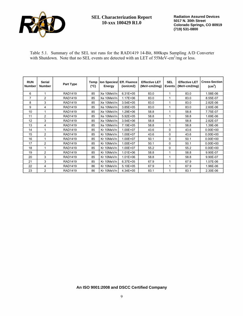
The units-under-test did not exhibit latch-up at any LETs of 55MeV-cm2/mg or lower. SEL events were recorded and characterized using LETs from 58MeV-cm2/mg to 83MeV-cm2/mg. The SEL events were non-destructive and have a very low limiting cross-section of <3E-06cm2/device. Therefore the RAD1419
14-Bit ADC has a “worst-case” geosynchronous SEL rate of <8E-08 events/device-day or an MTBF of 12.5-million days. An equivalent failure in
time (FIT) rate is approximately 3 failures/billion device-hours

SEL Characterization Report 10-xxx 100429 R1.0
An ISO 9001:2008 and DSCC Certified Company
2
Radiation Assured Devices5017 N. 30th Street Colorado Springs, CO 80919 (719) 531-0800
1.0. Overview and Background It is well known that heavy ion exposure can cause single event effects that can lead to temporary and/or permanent damage in electronic devices. The events can occur through various mechanisms including single event latch-up (SEL), single event burnout (SEB) and single event gate rupture (SEGR). An SEL event occurs when a parasitic npnp feedback latch structure becomes biased into the on state due to a dense track of electron-hole pairs created along the heavy ion path in silicon. This latch-up is self-sustaining since there is a positive feedback path created and requires a power cycle to reset. A single event latch-up can non-destructive or destructive. A non-destructive SEL event occurs if the latch-up event is “self-limiting” while a destructive SEL event occurs if the current draw from the SEL event is sufficient to damage the junction and/or bond wire. The damage can become worse and/or becomes evident with increasing linear energy transfer (LET) and fluence. The two test standards most frequently used to govern this testing are ASTM F1192 and EIA/JESD57. Single event latch-up testing is usually performed at the maximum datasheet voltage and temperature to a total fluence of not less than 1E7ion/cm2. 2.0. Single Event Latch-Up Test Apparatus The single event latch-up testing described in this final report was performed at the Lawrence Berkeley National Laboratories (LBNL) using the 88-Inch Cyclotron. The 88-Inch Cyclotron is operated by the University of California for the US Department of Energy (DOE) and is a K=140 sector-focused cyclotron with both light- and heavy-ion capabilities. Protons and other light-ions are available at high intensities (10-20pμA) up to maximum energies of 55 MeV (protons), 65 MeV (deuterons), 135 MeV (3He) and 140 MeV (4He). Most heavy ions through uranium can be accelerated to maximum energies, which vary with the mass and charge state. For the SEL testing described in this final report the devices were placed in the Cave 4B vacuum chamber aligned with the heavy ion beam line. The test platter in the vacuum chamber has full x and y alignment capabilities along with 2-dimensional rotation, allowing for a variety of effective LETs for each ion. For SEE testing Lawrence Berkeley Laboratories provides the dosimetry via a local control computer running a Lab View based program. Each ion is calibrated just prior to use using five photomultiplier tubes (PMTs). Four of the five PMTS are used during the test to provide the beam statistics, while the center PMT is removed following calibration. Figure 2.1 shows an illustration of the LBL facility; including the location of Cave 4B, where the heavy ion SEE testing took place.

SEL Characterization Report 10-xxx 100429 R1.0
An ISO 9001:2008 and DSCC Certified Company
3
Radiation Assured Devices5017 N. 30th Street Colorado Springs, CO 80919 (719) 531-0800
Figure 2.1. Map of 88-Inch Cyclotron Facility showing the location of Cave 4B, where the SEE testing wasperformed.

SEL Characterization Report 10-xxx 100429 R1.0
An ISO 9001:2008 and DSCC Certified Company
4
Radiation Assured Devices5017 N. 30th Street Colorado Springs, CO 80919 (719) 531-0800
3.0. Radiation Test Conditions
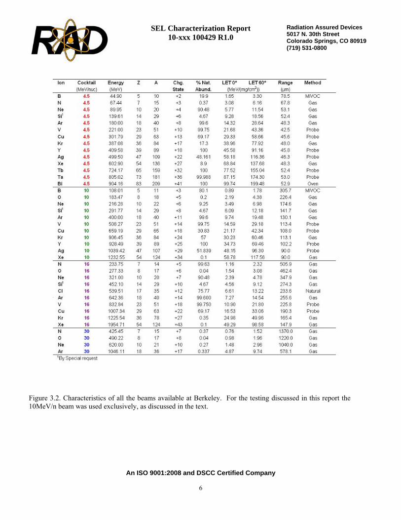
The RAD1419 14-Bit, 800ksps Sampling A/D Converter with Shutdown described in this final report was irradiated using Kr and Xe with a split positive supply potential of 5.5V and at a maximum case temperature of 85°C. See the Bias Table in Appendix B for the specific details of the bias conditions. The 10MeV/n beam was used to provide sufficient range in silicon while meeting the maximum LET requirements of the program. The other beams available at Berkeley are the 4.5MeV/n beam and the 16MeV/n beam. The 4.5MeV/n beam does not provide sufficient range for destructive SEE testing while the 16MeV/n beam provides a much smaller selection of ions. Figure 3.1 shows the 10MeV/n beam characteristics for Xe. As seen in the figure, the range to the Bragg Peak is approximately 60μm while the surface LET is approximately 58MeV-cm2/mg. Note that the units were decapsulated prior to testing and all exposures took place from the top surface providing a distance to the active layer in Silicon of approximately 5 to 10μm. Figure 3.2 shows the characteristics for all the beams available at Berkeley. The devices were irradiated to a minimum fluence of 1E7ion/cm2 for each run or until a latch-up event was detected. The flux varied somewhat during the testing, but was consistently targeted to approximately to between 2E5ion/cm2-s and 5E5ion/cm2-s. As noted, the irradiation of the units-under-test continued until either the minimum fluence was reached or a latchup event was observed. For the elevated temperature required for single event latch-up testing an aluminum plate heater fixed to the back of the board and was used to heat the device-under-test (DUT) with an RTD used to monitor the temperature. The case temperature of the DUT was calibrated prior to the testing to the RTD with a thermocouple, allowing the RTD to provide feedback and maintain a calibrated 85°C case temperature throughout the testing. The data monitored during the test (case temperature, supply voltage and supply current) was routed to the control room (approximately 20-feet away) using shielded coaxial cable.

SEL Characterization Report 10-xxx 100429 R1.0
An ISO 9001:2008 and DSCC Certified Company
5
Radiation Assured Devices5017 N. 30th Street Colorado Springs, CO 80919 (719) 531-0800
Figure 3.1. Range of the 10MeV/n Kr and Xe beam into silicon. The range to the Bragg Peak is approximately80μm and 60μm while the surface LET is approximately 32MeV-cm2/mg and 58MeV-cm2/mg for Kr and Xe,respectively.
0.0
10.0
20.0
30.0
40.0
50.0
60.0
70.0
80.0
0 20 40 60 80 100 120
Depth in Si (micron)
LET
(MeV
/mg/
cm2)
86Kr
136Xe
SEL Characterization Report 10-xxx 100429 R1.0
An ISO 9001:2008 and DSCC Certified Company
6
Radiation Assured Devices5017 N. 30th Street Colorado Springs, CO 80919 (719) 531-0800
Figure 3.2. Characteristics of all the beams available at Berkeley. For the testing discussed in this report the10MeV/n beam was used exclusively, as discussed in the text.

SEL Characterization Report 10-xxx 100429 R1.0
An ISO 9001:2008 and DSCC Certified Company
7
Radiation Assured Devices5017 N. 30th Street Colorado Springs, CO 80919 (719) 531-0800
4.0. Tested Parameters During heavy ion exposure, the supply current to the unit-under-test was measured and recorded in approximately 1-second increments. A plot of supply current versus time/fluence for each of the heavy ion exposures is included in this final report. In addition to recording the supply current, the gross functionality of the device was monitored following the exposure and before power was cycled when the units under test did not latch-up. A full parametric test was also performed on all four SEL test units using the RAD1419 production test program approximately 3-days following the SEL testing. In general the following two criteria must be met for a device to pass SEL testing: 1) SEL “immunity” to a minimum specified LET. This test is characterized by a heavy ion exposure to the minimum LET specified, typically 40MeV-cm2/mg to 80MeV-cm2/mg where the supply current must remain within the unit’s pre-exposure supply specification limits without cycling power, the unit-under-test must remain functional following the radiation exposure also without the need to cycle power. Finally, the SEL test units under test must pass a parametric test at some point following the SEL exposure to ensure no significant degradation occurred due to undetected events; or 2) SEL “characterization”. SEL characterization establishes the LET threshold and limiting cross-section, determines if the SEL events are destructive or non-destructive by verifying gross functionality immediately following a power cycle. These units also must pass a parametric test at some point following the SEL exposure to ensure no significant degradation occurred due to the detected or undetected SEL events. Once the characterization is complete the SEL threshold and cross-section data is used with a space radiation modeling code (such as CREME96) to determine if the SEL rate is acceptable for the mission application. If any of these conditions are not satisfied following the heavy ion testing, then the units (from the lot date code tested) could be logged as an SEL failure and may not be suitable for space flight application. Note that during heavy ion testing a substantial amount of total dose can be absorbed by the units-under-test. If a functional or parameter failure occurs during or following the SEL testing, it is important to separate TID failures from destructive single event effects. 5.0. Single Event Latch-Up Test Results The RAD1419 14-Bit, 800ksps Sampling A/D Converter with Shutdown SEL test units-under-test did not exhibit latch-up at any LETs of 55MeV-cm2/mg or lower. SEL events were recorded and characterized using LETs from 58MeV-cm2/mg to 83MeV-cm2/mg. The SEL events were non-destructive and have a very low limiting cross-section of <3E-06cm2/device. The SEL events were considered non-destructive by verifying gross functionality at the beam facility and then by running a full parametric characterization approximately 3-days later. Using CREME96 we can calculate SEL event rate for a “worst-case” geosynchronous orbit to determine if these units are suitable for space flight applications. Based on the SEL characterization data shown in this report and CREME96, the RAD1419 14-Bit ADC has a “worst-case” geosynchronous SEL rate of <8E-08 events/device-day or an MTBF of 12.5-million days. An equivalent failure in time (FIT) rate is approximately 3 failures/billion device-hours. See Appendix D for the output of the CREME96 run for

SEL Characterization Report 10-xxx 100429 R1.0
An ISO 9001:2008 and DSCC Certified Company
8
Radiation Assured Devices5017 N. 30th Street Colorado Springs, CO 80919 (719) 531-0800
the details of the orbit parameters used in the above calculations. Note that the overall reliability of space flight electronics due to failure from random defects in the material is on the order of 10 to 100 FITs. Therefore the probability of an SEL event is much lower than the probability of a random failure of the components in the system. Also note that the code was run for a geosynchronous orbit. Running the code at lower orbit altitudes will cause the FIT rate to drop substantially. Table 5.1 shows a summary of the single event latch-up data acquired. The table shows the run number, the serial number of the part irradiated, the ion species, the effective LET of the irradiating particle, the case temperature during testing, the number of SEL events observed during the run, the effective fluence and the SEL cross-section. Figure 5.1 shows a plot of the SEL characterization data (solid diamonds) and a Weibull fit to the data. As seen in this figure the units-under-test exhibit a relatively high LET threshold and a very low SEL cross-section per device at the highest LET test of 80MeV-cm2/mg. Figures 5.2 through 5.15 show the supply current data during the SEL runs. In these figures the supply current is plotted as a function of time and the total fluence for each run can be found in Table 5.1. As seen in these figure, when an SEL event occurs the supply current for each supply jumps to approximately 300mA for each supply (+5V nominal supply and the –5V nominal supply). This current is “self regulating”, that is there was no current limiting resistor inline with the power supply pins and the power supply was set to a compliance of 1A. In all cases, the supply current and gross functionality of the device were restored following a power cycle to the unit-under-test.
SEL Characterization Report 10-xxx 100429 R1.0
An ISO 9001:2008 and DSCC Certified Company
9
Radiation Assured Devices5017 N. 30th Street Colorado Springs, CO 80919 (719) 531-0800
RUNNumber
SerialNumber Part Type Temp
(°C)Ion Species/
EnergyEff. Fluence
(ion/cm2)Effective LET(MeV-cm2/mg)
SEL Events
Effective LET(MeV-cm2/mg)
Cross-Section(cm2)
6 1 RAD1419 85 Xe 10MeV/n 6.31E+05 83.0 1 83.0 1.58E-067 2 RAD1419 85 Xe 10MeV/n 1.17E+06 83.0 1 83.0 8.55E-078 3 RAD1419 85 Xe 10MeV/n 3.54E+05 83.0 1 83.0 2.82E-069 4 RAD1419 85 Xe 10MeV/n 3.85E+05 83.0 1 83.0 2.60E-0610 1 RAD1419 85 Xe 10MeV/n 1.29E+06 58.8 1 58.8 7.75E-0711 2 RAD1419 85 Xe 10MeV/n 5.92E+05 58.8 1 58.8 1.69E-0612 3 RAD1419 85 Xe 10MeV/n 3.54E+06 58.8 1 58.8 2.82E-0713 4 RAD1419 85 Xe 10MeV/n 7.19E+05 58.8 1 58.8 1.39E-0614 1 RAD1419 85 Kr 10MeV/n 1.00E+07 43.6 0 43.6 0.00E+0015 2 RAD1419 85 Kr 10MeV/n 1.00E+07 43.6 0 43.6 0.00E+0016 1 RAD1419 85 Kr 10MeV/n 1.00E+07 50.1 0 50.1 0.00E+0017 2 RAD1419 85 Kr 10MeV/n 1.00E+07 50.1 0 50.1 0.00E+0018 1 RAD1419 85 Kr 10MeV/n 1.00E+07 55.2 0 55.2 0.00E+0019 2 RAD1419 85 Kr 10MeV/n 1.01E+06 58.8 1 58.8 9.90E-0720 3 RAD1419 85 Kr 10MeV/n 1.01E+06 58.8 1 58.8 9.90E-0721 3 RAD1419 85 Kr 10MeV/n 6.37E+05 67.9 1 67.9 1.57E-0622 4 RAD1419 86 Kr 10MeV/n 5.10E+05 67.9 1 67.9 1.96E-0623 2 RAD1419 86 Kr 10MeV/n 4.34E+05 83.1 1 83.1 2.30E-06
Table 5.1. Summary of the SEL test runs for the RAD1419 14-Bit, 800ksps Sampling A/D Converterwith Shutdown. Note that no SEL events are detected with an LET of 55MeV-cm2/mg or less.

SEL Characterization Report 10-xxx 100429 R1.0
An ISO 9001:2008 and DSCC Certified Company
10
Radiation Assured Devices5017 N. 30th Street Colorado Springs, CO 80919 (719) 531-0800
1.00E-08
1.00E-07
1.00E-06
1.00E-05
1.00E-04
0 10 20 30 40 50 60 70 80 90
LET (MeV-cm2/mg)
SEL
Cro
ss S
ectio
n (c
m2/
devi
ce)
Figure 5.1. SEL cross-section (cm2/device) versus LET for the RAD1419 ADC tested at 85°C and at the worst-case supply potential of ±5.5V. As seen in this figure the units are susceptible to SEL events with a relativelyhigh onset LET of greater than 55MeV-cm2/mg and a very low SEL cross-section per device of approximately3E-6cm2/device at the maximum tested LET of approximately 80MeV-cm2/mg. Note that this is not the limitingor saturated cross-section since the cross-section may not have fully saturated with increasing LET.

SEL Characterization Report 10-xxx 100429 R1.0
An ISO 9001:2008 and DSCC Certified Company
11
Radiation Assured Devices5017 N. 30th Street Colorado Springs, CO 80919 (719) 531-0800
Figure 5.2. Supply current versus time for the RAD1419 14-Bit ADC serial numbers 1 and 2. The units were tested with ±5.5V on the VS+ and VS- lines and at a case temperature of 85°C. The total fluence to the devicecan be found in Table 5.1 and was 1E7ions/cm2 for all the runs shown in this figure since no SEL was observed.The data in this figure shows that the units-under-test are SEL “immune” at an effective LET of 55MeV-cm2/mg and lower when tested to a total fluence of 1E7ions/cm2. As noted in the text of this report the units remained functional following each run without cycling power and a verification of full parametric performance wasperformed approximately 3-days following the SEL testing, with all parts passing.
0 20 40 60 80 100 120 1400mA
20mA
40mA
60mA
80mA
+5V -5V LET 44 44 50 50 55
BeamOn
RAD1419 SN 1, T=85C, Runs 14-18
Supp
ly C
urre
nt
Time (Seconds)
SEL Characterization Report 10-xxx 100429 R1.0
An ISO 9001:2008 and DSCC Certified Company
12
Radiation Assured Devices5017 N. 30th Street Colorado Springs, CO 80919 (719) 531-0800
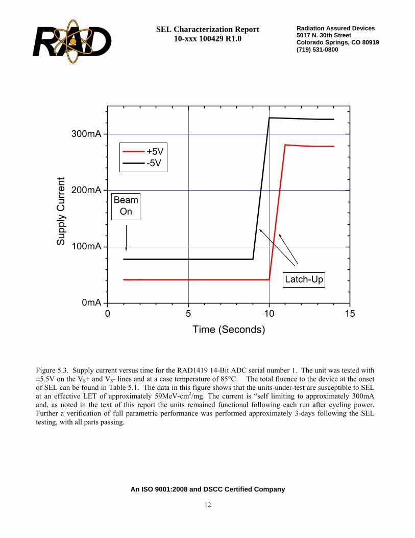
Figure 5.3. Supply current versus time for the RAD1419 14-Bit ADC serial number 1. The unit was tested with±5.5V on the VS+ and VS- lines and at a case temperature of 85°C. The total fluence to the device at the onsetof SEL can be found in Table 5.1. The data in this figure shows that the units-under-test are susceptible to SELat an effective LET of approximately 59MeV-cm2/mg. The current is “self limiting to approximately 300mAand, as noted in the text of this report the units remained functional following each run after cycling power.Further a verification of full parametric performance was performed approximately 3-days following the SELtesting, with all parts passing.
0 5 10 150mA
100mA
200mA
300mA
+5V -5V
Latch-Up
BeamOn
RAD1419 SN 1, T=85C, LET=59, Run 10
Supp
ly C
urre
nt
Time (Seconds)

SEL Characterization Report 10-xxx 100429 R1.0
An ISO 9001:2008 and DSCC Certified Company
13
Radiation Assured Devices5017 N. 30th Street Colorado Springs, CO 80919 (719) 531-0800
Figure 5.4. Supply current versus time for the RAD1419 14-Bit ADC serial number 2. The unit was tested with ±5.5V on the VS+ and VS- lines and at a case temperature of 85°C. The total fluence to the device at the onsetof SEL can be found in Table 5.1. The data in this figure shows that the units-under-test are susceptible to SEL at an effective LET of approximately 59MeV-cm2/mg. The current is “self limiting to approximately 300mAand, as noted in the text of this report the units remained functional following each run after cycling power.Further a verification of full parametric performance was performed approximately 3-days following the SEL testing, with all parts passing.
0 5 100mA
100mA
200mA
300mA
+5V -5V
Latch-Up
BeamOn
RAD1419 SN 1, T=85C, LET=59, Run 11
Supp
ly C
urre
nt
Time (Seconds)

SEL Characterization Report 10-xxx 100429 R1.0
An ISO 9001:2008 and DSCC Certified Company
14
Radiation Assured Devices5017 N. 30th Street Colorado Springs, CO 80919 (719) 531-0800
Figure 5.5. Supply current versus time for the RAD1419 14-Bit ADC serial number 3. The unit was tested with±5.5V on the VS+ and VS- lines and at a case temperature of 85°C. The total fluence to the device at the onsetof SEL can be found in Table 5.1. The data in this figure shows that the units-under-test are susceptible to SELat an effective LET of approximately 59MeV-cm2/mg. The current is “self limiting to approximately 300mAand, as noted in the text of this report the units remained functional following each run after cycling power.Further a verification of full parametric performance was performed approximately 3-days following the SELtesting, with all parts passing.
0 5 10 15 20 25 300mA
100mA
200mA
300mA +5V -5V
Latch-Up
BeamOn
RAD1419 SN 1, T=85C, LET=59, Run 12
Supp
ly C
urre
nt
Time (Seconds)
SEL Characterization Report 10-xxx 100429 R1.0
An ISO 9001:2008 and DSCC Certified Company
15
Radiation Assured Devices5017 N. 30th Street Colorado Springs, CO 80919 (719) 531-0800
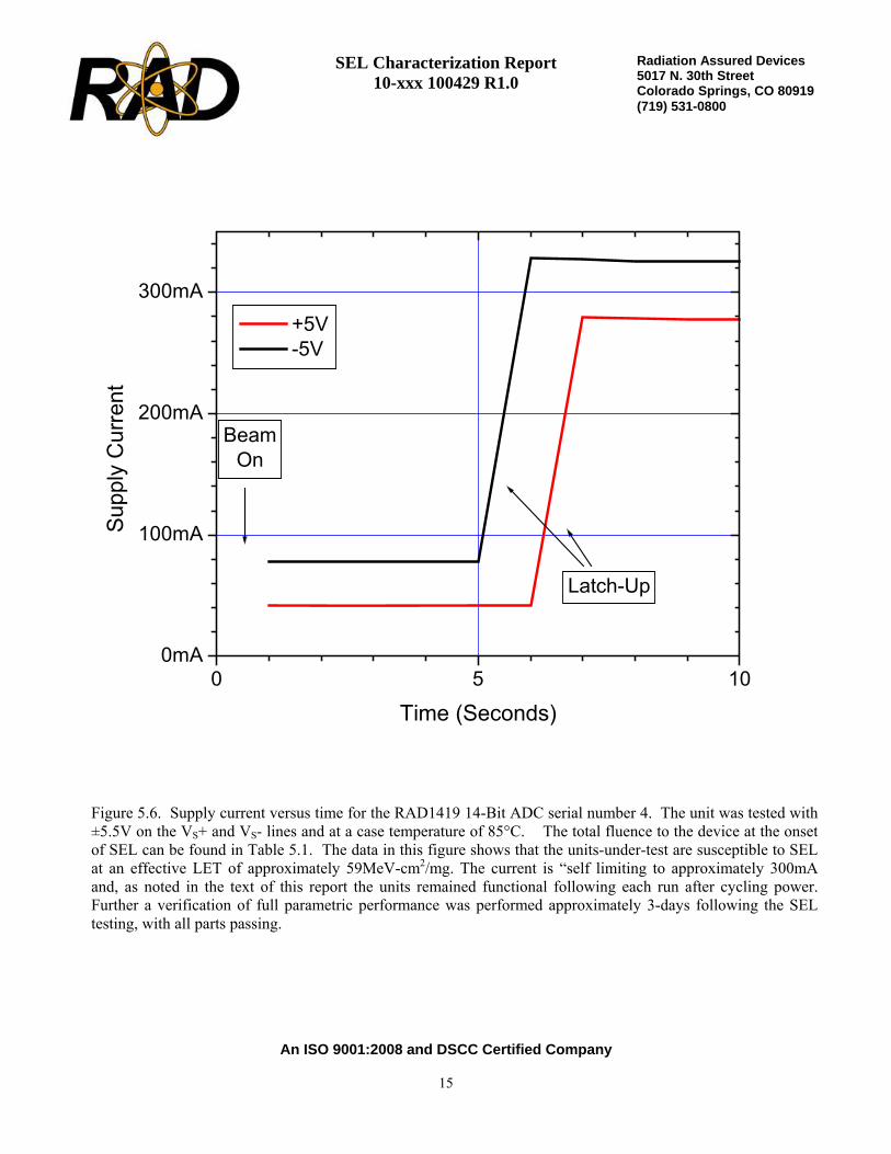
Figure 5.6. Supply current versus time for the RAD1419 14-Bit ADC serial number 4. The unit was tested with ±5.5V on the VS+ and VS- lines and at a case temperature of 85°C. The total fluence to the device at the onsetof SEL can be found in Table 5.1. The data in this figure shows that the units-under-test are susceptible to SEL at an effective LET of approximately 59MeV-cm2/mg. The current is “self limiting to approximately 300mAand, as noted in the text of this report the units remained functional following each run after cycling power. Further a verification of full parametric performance was performed approximately 3-days following the SEL testing, with all parts passing.
0 5 100mA
100mA
200mA
300mA +5V -5V
Latch-Up
BeamOn
RAD1419 SN 1, T=85C, LET=59, Run 13
Supp
ly C
urre
nt
Time (Seconds)

SEL Characterization Report 10-xxx 100429 R1.0
An ISO 9001:2008 and DSCC Certified Company
16
Radiation Assured Devices5017 N. 30th Street Colorado Springs, CO 80919 (719) 531-0800
Figure 5.7. Supply current versus time for the RAD1419 14-Bit ADC serial number 2. The unit was tested with ±5.5V on the VS+ and VS- lines and at a case temperature of 85°C. The total fluence to the device at the onset of SEL can be found in Table 5.1. The data in this figure shows that the units-under-test are susceptible to SEL at an effective LET of approximately 59MeV-cm2/mg. The current is “self limiting to approximately 300mAand, as noted in the text of this report the units remained functional following each run after cycling power.Further a verification of full parametric performance was performed approximately 3-days following the SEL testing, with all parts passing.
0 5 10 15 200mA
100mA
200mA
300mA
Latch-Up
+5V -5V
BeamOn
RAD1419 SN 2, T=85C, LET=59, Run 19
Supp
ly C
urre
nt
Time (Seconds)

SEL Characterization Report 10-xxx 100429 R1.0
An ISO 9001:2008 and DSCC Certified Company
17
Radiation Assured Devices5017 N. 30th Street Colorado Springs, CO 80919 (719) 531-0800
Figure 5.8. Supply current versus time for the RAD1419 14-Bit ADC serial number 3. The unit was tested with±5.5V on the VS+ and VS- lines and at a case temperature of 85°C. The total fluence to the device at the onsetof SEL can be found in Table 5.1. The data in this figure shows that the units-under-test are susceptible to SELat an effective LET of approximately 59MeV-cm2/mg. The current is “self limiting to approximately 300mAand, as noted in the text of this report the units remained functional following each run after cycling power.Further a verification of full parametric performance was performed approximately 3-days following the SELtesting, with all parts passing.
0 5 10 15 200mA
100mA
200mA
300mA
Latch-Up
+5V -5V
BeamOn
RAD1419 SN 2, T=85C, LET=59, Run 20
Supp
ly C
urre
nt
Time (Seconds)

SEL Characterization Report 10-xxx 100429 R1.0
An ISO 9001:2008 and DSCC Certified Company
18
Radiation Assured Devices5017 N. 30th Street Colorado Springs, CO 80919 (719) 531-0800
Figure 5.9. Supply current versus time for the RAD1419 14-Bit ADC serial number 3. The unit was tested with±5.5V on the VS+ and VS- lines and at a case temperature of 85°C. The total fluence to the device at the onsetof SEL can be found in Table 5.1. The data in this figure shows that the units-under-test are susceptible to SELat an effective LET of approximately 68MeV-cm2/mg. The current is “self limiting to approximately 300mAand, as noted in the text of this report the units remained functional following each run after cycling power.Further a verification of full parametric performance was performed approximately 3-days following the SELtesting, with all parts passing.
0 5 100mA
100mA
200mA
300mA
Latch-Up
+5V -5V
BeamOn
RAD1419 SN 2, T=85C, LET=68, Run 21
Supp
ly C
urre
nt
Time (Seconds)

SEL Characterization Report 10-xxx 100429 R1.0
An ISO 9001:2008 and DSCC Certified Company
19
Radiation Assured Devices5017 N. 30th Street Colorado Springs, CO 80919 (719) 531-0800
Figure 5.10. Supply current versus time for the RAD1419 14-Bit ADC serial number 4. The unit was tested with ±5.5V on the VS+ and VS- lines and at a case temperature of 85°C. The total fluence to the device at theonset of SEL can be found in Table 5.1. The data in this figure shows that the units-under-test are susceptible to SEL at an effective LET of approximately 68MeV-cm2/mg. The current is “self limiting to approximately 300mA and, as noted in the text of this report the units remained functional following each run after cycling power. Further a verification of full parametric performance was performed approximately 3-days following the SEL testing, with all parts passing.
0 5 10 15 200mA
100mA
200mA
300mA
Latch-Up
+5V -5V
BeamOn
RAD1419 SN 2, T=85C, LET=68, Run 22
Supp
ly C
urre
nt
Time (Seconds)

SEL Characterization Report 10-xxx 100429 R1.0
An ISO 9001:2008 and DSCC Certified Company
20
Radiation Assured Devices5017 N. 30th Street Colorado Springs, CO 80919 (719) 531-0800
Figure 5.11. Supply current versus time for the RAD1419 14-Bit ADC serial number 1. The unit was tested with ±5.5V on the VS+ and VS- lines and at a case temperature of 85°C. The total fluence to the device at theonset of SEL can be found in Table 5.1. The data in this figure shows that the units-under-test are susceptible to SEL at an effective LET of approximately 83MeV-cm2/mg. The current is “self limiting to approximately 300mA and, as noted in the text of this report the units remained functional following each run after cyclingpower. Further a verification of full parametric performance was performed approximately 3-days following the SEL testing, with all parts passing.
0 5 10 15 200mA
100mA
200mA
300mA
+5V -5V
Latch-Up
BeamOn
RAD1419 SN 1, T=85C, LET=83, Run 6
Supp
ly C
urre
nt
Time (Seconds)

SEL Characterization Report 10-xxx 100429 R1.0
An ISO 9001:2008 and DSCC Certified Company
21
Radiation Assured Devices5017 N. 30th Street Colorado Springs, CO 80919 (719) 531-0800
Figure 5.12. Supply current versus time for the RAD1419 14-Bit ADC serial number 2. The unit was tested with ±5.5V on the VS+ and VS- lines and at a case temperature of 85°C. The total fluence to the device at the onset of SEL can be found in Table 5.1. The data in this figure shows that the units-under-test are susceptible to SEL at an effective LET of approximately 83MeV-cm2/mg. The current is “self limiting to approximately 300mA and, as noted in the text of this report the units remained functional following each run after cyclingpower. Further a verification of full parametric performance was performed approximately 3-days following the SEL testing, with all parts passing.
0 5 10 15 20 250mA
100mA
200mA
300mA
+5V -5V
Latch-Up
BeamOn
RAD1419 SN 1, T=85C, LET=83, Run 7
Supp
ly C
urre
nt
Time (Seconds)

SEL Characterization Report 10-xxx 100429 R1.0
An ISO 9001:2008 and DSCC Certified Company
22
Radiation Assured Devices5017 N. 30th Street Colorado Springs, CO 80919 (719) 531-0800
Figure 5.13. Supply current versus time for the RAD1419 14-Bit ADC serial number 3. The unit was tested with ±5.5V on the VS+ and VS- lines and at a case temperature of 85°C. The total fluence to the device at the onset of SEL can be found in Table 5.1. The data in this figure shows that the units-under-test are susceptible to SEL at an effective LET of approximately 83MeV-cm2/mg. The current is “self limiting to approximately 300mA and, as noted in the text of this report the units remained functional following each run after cyclingpower. Further a verification of full parametric performance was performed approximately 3-days following the SEL testing, with all parts passing.
0 5 10 15 20 250mA
100mA
200mA
300mA
+5V -5V
Latch-Up
BeamOn
RAD1419 SN 1, T=85C, LET=83, Run 8
Supp
ly C
urre
nt
Time (Seconds)
SEL Characterization Report 10-xxx 100429 R1.0
An ISO 9001:2008 and DSCC Certified Company
23
Radiation Assured Devices5017 N. 30th Street Colorado Springs, CO 80919 (719) 531-0800
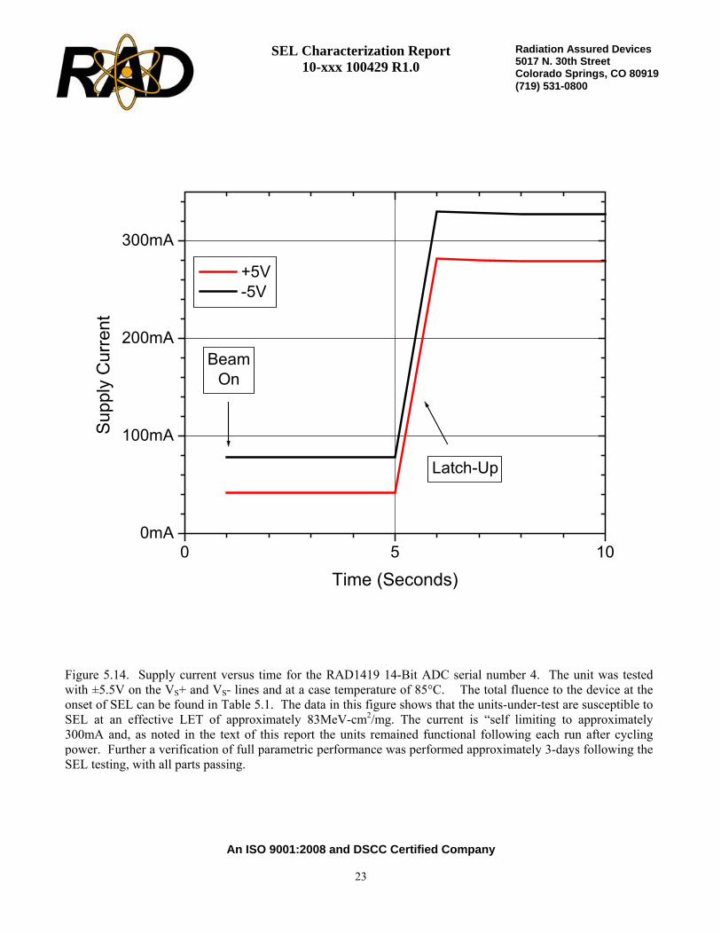
Figure 5.14. Supply current versus time for the RAD1419 14-Bit ADC serial number 4. The unit was tested with ±5.5V on the VS+ and VS- lines and at a case temperature of 85°C. The total fluence to the device at the onset of SEL can be found in Table 5.1. The data in this figure shows that the units-under-test are susceptible to SEL at an effective LET of approximately 83MeV-cm2/mg. The current is “self limiting to approximately 300mA and, as noted in the text of this report the units remained functional following each run after cyclingpower. Further a verification of full parametric performance was performed approximately 3-days following the SEL testing, with all parts passing.
0 5 100mA
100mA
200mA
300mA
+5V -5V
Latch-Up
BeamOn
RAD1419 SN 1, T=85C, LET=83, Run 9
Supp
ly C
urre
nt
Time (Seconds)

SEL Characterization Report 10-xxx 100429 R1.0
An ISO 9001:2008 and DSCC Certified Company
24
Radiation Assured Devices5017 N. 30th Street Colorado Springs, CO 80919 (719) 531-0800
Figure 5.15. Supply current versus time for the RAD1419 14-Bit ADC serial number 2. The unit was testedwith ±5.5V on the VS+ and VS- lines and at a case temperature of 85°C. The total fluence to the device at theonset of SEL can be found in Table 5.1. The data in this figure shows that the units-under-test are susceptible toSEL at an effective LET of approximately 83MeV-cm2/mg. The current is “self limiting to approximately300mA and, as noted in the text of this report the units remained functional following each run after cyclingpower. Further a verification of full parametric performance was performed approximately 3-days following theSEL testing, with all parts passing.
0 5 100mA
100mA
200mA
300mA
Latch-Up
+5V -5V
BeamOn
RAD1419 SN 2, T=85C, LET=83, Run 23
Supp
ly C
urre
nt
Time (Seconds)

SEL Characterization Report 10-xxx 100429 R1.0
An ISO 9001:2008 and DSCC Certified Company
25
Radiation Assured Devices5017 N. 30th Street Colorado Springs, CO 80919 (719) 531-0800
6.0. Summary/Conclusions The single event latch-up testing described in this final report was performed at the Lawrence Berkeley National Laboratories (LBNL) using the 88-Inch Cyclotron. The 88-Inch Cyclotron is operated by the University of California for the US Department of Energy (DOE) and is a K=140 sector-focused cyclotron with both light- and heavy-ion capabilities. Protons and other light-ions are available at high intensities (10-20pμA) up to maximum energies of 55 MeV (protons), 65 MeV (deuterons), 135 MeV (3He) and 140 MeV (4He). Most heavy ions through uranium can be accelerated to maximum energies, which vary with the mass and charge state. The RAD1419 14-Bit, 800ksps Sampling A/D Converter with Shutdown described in this final report was irradiated using Kr and Xe with a split positive supply potential of 5.5V and at a maximum case temperature of 85°C. The 10MeV/n beam was used to provide sufficient range in silicon while meeting the maximum LET requirements of the program. The devices were irradiated to a minimum fluence of 1E7ion/cm2 for each run or until a latch-up event was detected. The flux varied somewhat during the testing, but was consistently targeted to between 2E5ion/cm2-s and 5E5ion/cm2-s. The RAD1419 14-Bit, 800ksps Sampling A/D Converter SEL test units-under-test did not exhibit latch-up at any LETs of 55MeV-cm2/mg or lower. SEL events were recorded and characterized using LETs from 58MeV-cm2/mg to 83MeV-cm2/mg. The SEL events were non-destructive and have a very low limiting cross-section of <3E-06cm2/device. The SEL events were considered non-destructive by verifying gross functionality at the beam facility and then by running a full parametric characterization approximately 3-days later. Using CREME96 we can calculate the SEL event rate for a “worst-case” geosynchronous orbit to determine if these units are suitable for space flight applications. Based on the SEL characterization data shown in this report and CREME96, the RAD1419 14-Bit ADC has a “worst-case” geosynchronous SEL rate of <8E-08 events/device-day or an MTBF of 12.5-million days. An equivalent failure in time (FIT) rate is approximately 3 failures/billion device-hours. Note that the overall reliability of space flight electronics due to failure from random defects in the material is on the order of 10 to 100 FITs. Therefore the probability of an SEL event is much lower than the probability of a random failure of the components in the system. Also note that the code was run for a geosynchronous orbit. Running the code at lower orbit altitudes will cause the FIT rate to drop substantially.

SEL Characterization Report 10-xxx 100429 R1.0
An ISO 9001:2008 and DSCC Certified Company
26
Radiation Assured Devices5017 N. 30th Street Colorado Springs, CO 80919 (719) 531-0800
Appendix A: Photograph of Sample Unit-Under-Test to Show Device Traceability

SEL Characterization Report 10-xxx 100429 R1.0
An ISO 9001:2008 and DSCC Certified Company
27
Radiation Assured Devices5017 N. 30th Street Colorado Springs, CO 80919 (719) 531-0800
Appendix B: SEL Bias Connections
Biased Samples:
FUNCTION PIN NUMBER BIAS CONNECTIONS DURING IRRADIATION
+AIN 1 +2.5V, 1000pF Ceramic to -AIN -AIN 2 GND VREF 3 10μF Ceramic to GND
REFCOMP 4 10μF Ceramic to GND AGND 5 GND
D13 (MSB) 6 Open D12 7 Open D11 8 Open D10 9 Open D9 10 Open D8 11 Open D7 12 Open D6 13 Open
DGND 14 GND D5 15 Open D4 16 Open D3 17 Open D2 18 Open D1 19 Open D0 20 Open
SHDN/ 21 +5.5 V ± 0.15 V RD/ 22 GND
CONVST/ 23 500 kHz Square Wave @ 5 % Duty Cycle CS/ 24 GND
BUSY/ 25 Open VSS 26 -5.5 V ± 0.15 V, 10μF Ceramic to GND
DVDD 27 Pin 28 AVDD 28 +5.5 V ± 0.15 V, 10μF Ceramic to GND

SEL Characterization Report 10-xxx 100429 R1.0
An ISO 9001:2008 and DSCC Certified Company
28
Radiation Assured Devices5017 N. 30th Street Colorado Springs, CO 80919 (719) 531-0800
Figure B.1. RAD1419 28-Pin Flat pack package drawing (for reference only).

SEL Characterization Report 10-xxx 100429 R1.0
An ISO 9001:2008 and DSCC Certified Company
29
Radiation Assured Devices5017 N. 30th Street Colorado Springs, CO 80919 (719) 531-0800
Appendix C: Post-SEL Electrical Test Parameters and Conditions All electrical tests for this device are performed on one of Radiation Assured Device’s LTS2020 Test Systems. The LTS2020 Test System is a programmable parametric tester that provides parameter measurements for a variety of digital, analog and mixed signal products including voltage regulators, voltage comparators, D to A and A to D converters. The LTS2020 Test System achieves accuracy and sensitivity through the use of software self-calibration and an internal relay matrix with separate family boards and custom personality adapter boards. The tester uses this relay matrix to connect the required test circuits, select the appropriate voltage / current sources and establish the needed measurement loops for all the tests performed. The measured parameters and test conditions are shown in Table C.1. A listing of the measurement precision/resolution for each parameter is shown in Table C.2. The precision/resolution values were obtained either from test data or from the DAC resolution of the LTS-2020. To generate the precision/resolution shown in Table C.2, one of the units-under-test was tested repetitively (a total of 10-times with re-insertion between tests) to obtain the average test value and standard deviation. Using this test data MIL-HDBK-814 90/90 KTL statistics were applied to the measured standard deviation to generate the final measurement range. This value encompasses the precision/resolution of all aspects of the test system, including the LTS2020 mainframe, family board, socket assembly and DUT board as well as insertion error. In some cases, the measurement resolution is limited by the internal DACs, which results in a measured standard deviation of zero. In these instances the precision/resolution will be reported back as the LSB of the DAC.

SEL Characterization Report 10-xxx 100429 R1.0
An ISO 9001:2008 and DSCC Certified Company
30
Radiation Assured Devices5017 N. 30th Street Colorado Springs, CO 80919 (719) 531-0800
Parameter Test Condition
Power Supply Current SHDN=VCC, CS=0 Power Supply Current, Nap Mode SHDN=0 CS=0 Power Supply Current, Sleep Mode SHDN=0 CS=1 Power Supply Current SHDN=1 CS=0 Power Supply Current, Nap Mode SHDN=0 CS=0 Power Supply Current, Sleep Mode SHDN=0 CS=1 VREF IOUT = 0 VOL D0-D13 IOUT = 1.6mA VOH D0-D13 IOUT = –200μA VOH0p2MA_BUSY IOUT = –200μA IOZH D0-D13 VOUT=5V, CS/ = High IOZLVO D0-13 VOUT=0V, CS/ = High IIL CS VIN=0V IIL RD VIN=0V IIL SHDN VIN=0V IIL CONVST VIN=0V IIH CS VIN=5V IIH RD VIN=5V IIH SHDN VIN=5V IIH CONVST VIN=5V +Analog Input Leakage Current VIN=2.5V -Analog Input Leakage Current VIN=-2.5V Bipolar Offset VDD = 5V, VSS = – 5V Bipolar Gain (Full Scale) Error VDD = 5V, VSS = – 5V Integral Linearity Error-Positive VDD = 5V, VSS = – 5V Integral Linearity Error-Negative VDD = 5V, VSS = – 5V Differential Linearity Error-Long VDD = 5V, VSS = – 5V Differential Linearity Error-Short VDD = 5V, VSS = – 5V SFDR 100kHz Input Signal THD 100kHz Input Signal, First 5 Harmonics SINAD 100kHz Input Signal
Table C.1. Measured post-SEL parameters and test conditions for the RAD1419.

SEL Characterization Report 10-xxx 100429 R1.0
An ISO 9001:2008 and DSCC Certified Company
31
Radiation Assured Devices5017 N. 30th Street Colorado Springs, CO 80919 (719) 531-0800
Parameter Spec Min Spec Max Precision (stdev*2.065)
ICCSHDN=1CS=0 2.00E-02 ±6.14E-05 ICCSHDN=0CS=0 3.00E-03 ±8.71E-06 ICCSHDN=0CS=1 3.00E-03 ±1.07E-05 IEESHDN=1CS=0 -3.00E-02 ±5.40E-05 IEESHDN=0CS=0 -5.00E-04 ±8.26E-06 IEESHDN=0CS=1 -1.00E-04 ±1.81E-07 VREF 2.48E+00 2.52E+00 ±9.67E-16 VOL1p6MA_D0 4.00E-01 ±1.63E-03 VOL1p6MA_D1 4.00E-01 ±1.46E-03 VOL1p6MA_D2 4.00E-01 ±1.75E-03 VOL1p6MA_D3 4.00E-01 ±1.63E-03 VOL1p6MA_D4 4.00E-01 ±1.17E-03 VOL1p6MA_D5 4.00E-01 ±1.63E-03 VOL1p6MA_D6 4.00E-01 ±1.39E-03 VOL1p6MA_D7 4.00E-01 ±1.52E-03 VOL1p6MA_D8 4.00E-01 ±1.17E-03 VOL1p6MA_D9 4.00E-01 ±1.52E-03 VOL1p6MA_D10 4.00E-01 ±1.52E-03 VOL1p6MA_D11 4.00E-01 ±1.31E-03 VOL1p6MA_D12 4.00E-01 ±1.17E-03 VOL1p6MA_D13 4.00E-01 ±1.52E-03 VOH0p2MA_D0 4.00E+00 ±4.27E-03 VOH0p2MA_D1 4.00E+00 ±3.99E-03 VOH0p2MA_D2 4.00E+00 ±4.35E-03 VOH0p2MA_D3 4.00E+00 ±3.99E-03 VOH0p2MA_D4 4.00E+00 ±3.99E-03 VOH0p2MA_D5 4.00E+00 ±3.48E-03 VOH0p2MA_D6 4.00E+00 ±4.27E-03 VOH0p2MA_D7 4.00E+00 ±3.48E-03 VOH0p2MA_D8 4.00E+00 ±3.48E-03 VOH0p2MA_D9 4.00E+00 ±4.27E-03 VOH0p2MA_D10 4.00E+00 ±2.61E-03 VOH0p2MA_D11 4.00E+00 ±1.00E-03 VOH0p2MA_D12 4.00E+00 ±1.00E-03 VOH0p2MA_BUSY 4.00E+00 ±1.00E-03
Table C.2. Measured post-SEL parameters, pre-irradiation specifications and measurementresolution/precision for the RAD1419.

SEL Characterization Report 10-xxx 100429 R1.0
An ISO 9001:2008 and DSCC Certified Company
32
Radiation Assured Devices5017 N. 30th Street Colorado Springs, CO 80919 (719) 531-0800
VOH0p2MA_D13 4.00E+00 ±3.48E-03 IOZHVO=5V_D0 -1.00E-05 1.00E-05 ±2.95E-09 IOZHVO=5V_D1 -1.00E-05 1.00E-05 ±5.22E-09 IOZHVO=5V_D2 -1.00E-05 1.00E-05 ±3.54E-09 IOZHVO=5V_D3 -1.00E-05 1.00E-05 ±3.52E-09 IOZHVO=5V_D4 -1.00E-05 1.00E-05 ±3.92E-09 IOZHVO=5V_D5 -1.00E-05 1.00E-05 ±4.89E-09 IOZHVO=5V_D6 -1.00E-05 1.00E-05 ±4.87E-09 IOZHVO=5V_D7 -1.00E-05 1.00E-05 ±5.08E-09 IOZHVO=5V_D8 -1.00E-05 1.00E-05 ±6.06E-09 IOZHVO=5V_D9 -1.00E-05 1.00E-05 ±5.78E-09 IOZHVO=5V_D10 -1.00E-05 1.00E-05 ±3.65E-09 IOZHVO=5V_D11 -1.00E-05 1.00E-05 ±5.06E-09 IOZHVO=5V_D12 -1.00E-05 1.00E-05 ±4.27E-09 IOZHVO=5V_D13 -1.00E-05 1.00E-05 ±4.91E-09 IOZLVO=0V_D0 -1.00E-05 1.00E-05 ±3.48E-09 IOZLVO=0V_D1 -1.00E-05 1.00E-05 ±4.89E-09 IOZLVO=0V_D2 -1.00E-05 1.00E-05 ±3.89E-09 IOZLVO=0V_D3 -1.00E-05 1.00E-05 ±3.43E-09 IOZLVO=0V_D4 -1.00E-05 1.00E-05 ±4.27E-09 IOZLVO=0V_D5 -1.00E-05 1.00E-05 ±3.26E-09 IOZLVO=0V_D6 -1.00E-05 1.00E-05 ±3.57E-09 IOZLVO=0V_D7 -1.00E-05 1.00E-05 ±2.27E-09 IOZLVO=0V_D8 -1.00E-05 1.00E-05 ±2.58E-09 IOZLVO=0V_D9 -1.00E-05 1.00E-05 ±3.43E-09 IOZLVO=0V_D10 -1.00E-05 1.00E-05 ±3.40E-09 IOZLVO=0V_D11 -1.00E-05 1.00E-05 ±2.39E-09 IOZLVO=0V_D12 -1.00E-05 1.00E-05 ±2.83E-09 IOZLVO=0V_D13 -1.00E-05 1.00E-05 ±3.65E-09 IIL0V_CS -1.00E-05 1.00E-05 ±3.48E-09 IIL0V_RD -1.00E-05 1.00E-05 ±2.76E-09 IIL0V_SHDN -1.00E-05 1.00E-05 ±3.38E-09 IIL0V_CONVST -1.00E-05 1.00E-05 ±1.63E-09 IIH5V_CS -1.00E-05 1.00E-05 ±1.63E-09 IIH5V_RD -1.00E-05 1.00E-05 ±2.93E-09 IIH5V_SHDN -1.00E-05 1.00E-05 ±1.44E-09 IIH5V_CONVST -1.00E-05 1.00E-05 ±3.62E-09 IINp2p5VAIN -1.00E-06 1.00E-06 ±4.65E-08 IINm2p5VAIN -1.00E-06 1.00E-06 ±4.15E-08 BIPOLAROFFSET -2.00E+01 2.00E+01 ±1.65E-01 BIPOLARGAINERROR -6.00E+01 6.00E+01 ±2.43E-01 INT(p)NONmLIN 2.00E+00 ±1.79E-01 INT(m)NONmLIN -2.00E+00 ±1.34E-01

SEL Characterization Report 10-xxx 100429 R1.0
An ISO 9001:2008 and DSCC Certified Company
33
Radiation Assured Devices5017 N. 30th Street Colorado Springs, CO 80919 (719) 531-0800
CODEWIDTH(DNL)LONG 1.00E+00 2.50E+00 ±2.04E-01 CODEWIDTH(DNL)SHORT -5.00E+00 1.00E+00 ±9.99E-02 SFDR 8.60E+01 ±3.96E+00 THD -8.60E+01 ±4.10E-01 SINAD 7.80E+01 ±1.14E-01
Appendix D: CREME96 Orbit Definition Output File Created by CREME96:HI_UPSET_DRIVER Version 200 on 01-May-10 at 20:37:01 Input Integral LET Spectrum File: GEOSYNC.LET Created by CREME96:LETSPEC_DRIVER Version 200 on 18-Dec-07 at 22:15:43 ZMIN = 1 ZMAX = 92 LETMIN = 1.00E+00 LETMAX = 1.10E+05 MeV-cm2/g LBINS = 1002 EMINCUT = 1.00E-01 MeV/nuc TARGET MATERIAL = SILICON Input File to LETSPEC_DRIVER: GEOSYNC.TFX Created by CREME96:TRANSPORT_DRIVER Version 200 on 18-Dec-07 at 22:15:41 ZMIN = 1 ZMAX = 92 EMIN = 1.0000E-01 EMAX = 1.0000E+05 MeV/nuc MBINS = 1002 Thickness = 100.0000 mils ALUMINUM Input File to TRANSPORT_DRIVER: GEOSYNC.FLX Created by CREME96:FLUX_DRIVER Version 200 on 18-Dec-07 at 22:15:39 ZMIN = 1 ZMAX = 92 IMODE = 0 SOLAR-QUIET MODE: YEAR = 1977.0000 ITRANS = 0 GEOSYNCH/NEAR-EARTH INTERPLANETARY FLUXES