single drive converter cabinet units 55kw~500kw catalog ... · pdf filesinamics v50 single...
TRANSCRIPT

Single Drive Converter Cabinet Units
55KW~500KWCatalog D11.5﹒2008
SINAMICS V50
Catalog
D11.5﹒2008V1.0
The products and system described in this catalog are produced / distributed in accordance with the requirements of a quality management system which has been certified to DIN EN ISO 9001.
The certificate is recognized in all EQ Net countries.
1
Converter cabinet unitsapplications
FeaturesCabinet units
More standard configuration
Customer terminal blockCommunicationControl methodMore circumspect consideration
Technical dataSoftware and protection
2Selection and ordering data
Cabinet units
Options
3
Dimension drawings
55KW~90KW
110KW~250KW
315KW~500KW
5
AppendixEnvironment, resources and recycling
ISO 9001, ISO 14001
4
Engineering information
Customer terminal block
Technical data
Line-side components
Load-side components
Max. connectable cable length
Conductor cross-section and connection
Grounding
Motors
1
Overview
Application
Benefits
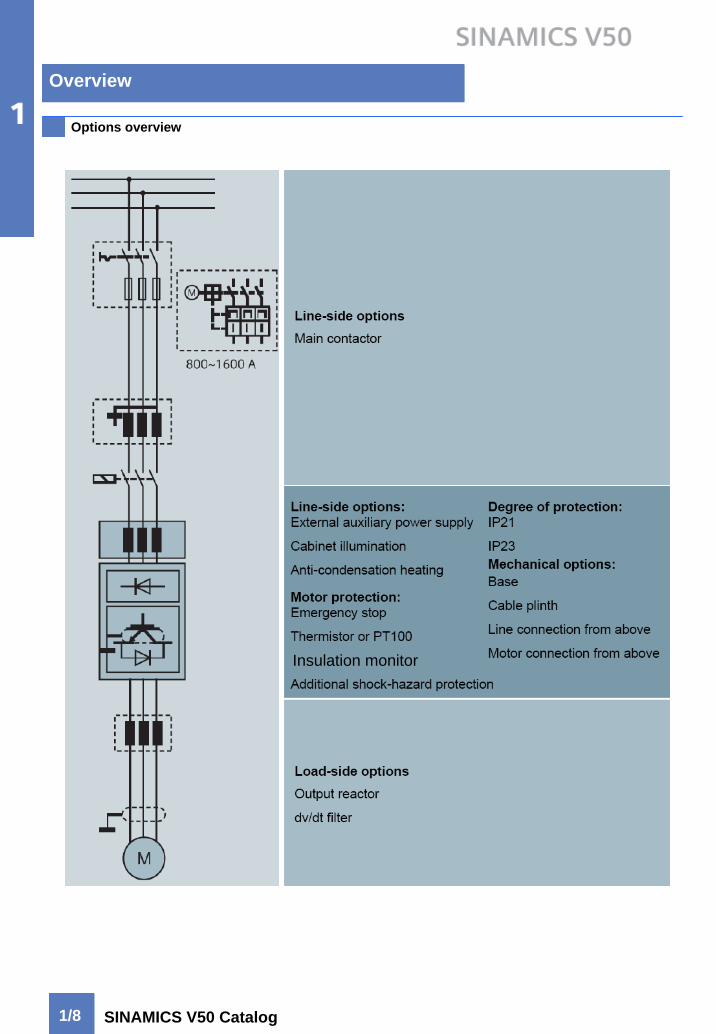
Options overview
Single Drive Converter Cabinet Units
SINAMICS V50Design
Functions
Technical data
OverviewSINAMICS V50
Application
Benefits
Design
Options overview
1/2
1/5
1/8
1/9
Functions
Technical data
Overview
1/2 SINAMICS V50 Catalog
Application
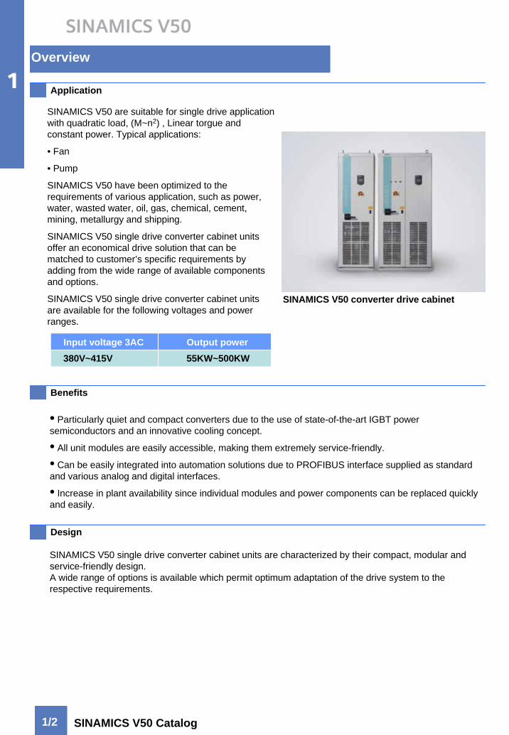
SINAMICS V50 are suitable for single drive application with quadratic load, (M~n2) , Linear torgue and constant power. Typical applications:
• Fan
• Pump
SINAMICS V50 have been optimized to the requirements of various application, such as power, water, wasted water, oil, gas, chemical, cement, mining, metallurgy and shipping.
SINAMICS V50 single drive converter cabinet units offer an economical drive solution that can be matched to customer’s specific requirements by adding from the wide range of available components and options.
SINAMICS V50 single drive converter cabinet units are available for the following voltages and power ranges.
Input voltage 3AC Output power380V~415V 55KW~500KW
SINAMICS V50 converter drive cabinet
• Particularly quiet and compact converters due to the use of state-of-the-art IGBT power semiconductors and an innovative cooling concept.
• All unit modules are easily accessible, making them extremely service-friendly.
• Can be easily integrated into automation solutions due to PROFIBUS interface supplied as standard and various analog and digital interfaces.
• Increase in plant availability since individual modules and power components can be replaced quickly and easily.
SINAMICS V50 single drive converter cabinet units are characterized by their compact, modular and service-friendly design.A wide range of options is available which permit optimum adaptation of the drive system to the respective requirements.
Benefits
Design

Overview
1/3SINAMICS V50 Catalog
Design
Input reactor
Switch with fuses
Customer terminal block
Line connection
Control unit
Power block
Cooling fan
Motor connection
SINAMICS V50 structure SINAMICS V50 standard configuration
Line connection
Main switch
Fuses
Main contactor (option)
Input reactor Uk=2%
Rectifier
Voltage DC link
Inverter
Motor connection
SINAMICS V50 basic design SINAMICS V50 connection diagram
More standard configuration• 8MF cabinet
• Degree of protection IP20 as standard
• Operation panel BOP2 as standard
• Input line connection terminal
• Output motor connection terminal
• Standard main switch with fuses
• Input reactor as standard
• EMC filter (2nd class)
• Power block
• cooling fan
• control board
• RS485 interface
• Analog/digital terminal interface block
• Protection cover
Overview
1/4 SINAMICS V50 Catalog
Design
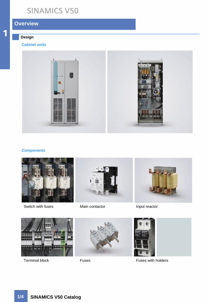
Switch with fuses Main contactor Input reactor
Terminal block Fuses Fuses with holders
Components
Cabinet units
Overview
1/5SINAMICS V50 Catalog
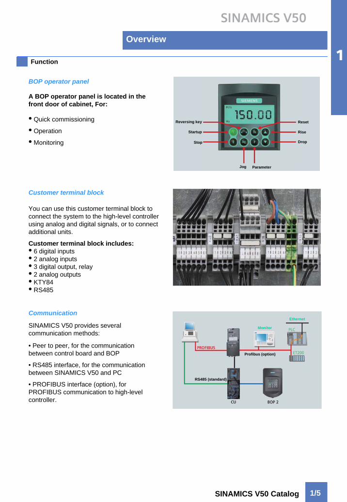
Function
• Quick commissioning
• Operation
• Monitoring
A BOP operator panel is located in the front door of cabinet, For:
BOP operator panel
Customer terminal block
You can use this customer terminal block to connect the system to the high-level controller using analog and digital signals, or to connect additional units.
Customer terminal block includes:• 6 digital inputs• 2 analog inputs• 3 digital output, relay• 2 analog outputs• KTY84• RS485
Communication
SINAMICS V50 provides several communication methods:
• Peer to peer, for the communication between control board and BOP
• RS485 interface, for the communication between SINAMICS V50 and PC
• PROFIBUS interface (option), for PROFIBUS communication to high-level controller.
RS485 (standard)
Profibus (option)
Monitor
Ethernet
Reversing key
Startup
Stop
Jog Parameter
Reset
Rise
Drop

Overview
1/6 SINAMICS V50 Catalog
Function (continued)
Control methods
Various control modes:
•V/F curved control
• V2/F
• Multiple-point V/F
• FCC
EMC filter as standard
SINAMICS V50 are equipped as standard with a EMC filter in accordance with the limit values specified in category C3, and passed the tests in accordance with EN61800-3 category C3.
Square torque linear torque Constant power

Overview
1/7SINAMICS V50 Catalog
Function (continued)
Software and protection functions
Software functions available as standard are described below:
Setpoint input The setpoint can be defined internally and externally, internally as fixed or motorized potentiometer or jog setpoints, externally via the communications interface or an analog input on the customer’s terminal block. The internal fixed setpoint and the motorized potentiometer setpoint can be switched over or adjusted usingcontrol commands via all interfaces.
Motor identification Automatic motor identification permits fast and simple commissioning and optimization of the drive control.
Ramp-function generator A user-friendly ramp-function generator with separately adjustable ramp-up and ramp-down times, together with adjustable rounding times in the lower and upper speed ranges, improves the control response and therefore prevents mechanical overloading of the drive train. The ramp-down ramps can be parameterized separately for emergency stop.
Vdc max controller The Vdc max controller automatically prevents overvoltages in the DC link if the set ramp-down ramp is tooshort, for example. This may also extend the set ramp-down time.
Flying restart The flying restart permits bumpless connection of the converter to a rotating motor.
Automatic restart The automatic restart switches the drive on again when the power is restored after a power failure, and ramps up to the current speed setpoint.
Technology controller The technology controller is designed as a PID controller. The P, I, and D components can be set separately.
I2t detection for motor protection
The motor temperature is calculated in a motor model stored in the converter software. The Motor protection is possible by means of connecting KTY84 or PTC sensors in the motor winding to converter.
Motor blocking prote A blocked motor is recognized and protected against thermal overloading by shutting down.
Ground fault monitoring Power unit protection
Electronic short-circuit Power unit protection
Thermal overload protection Power unit protection
Over current protection Power unit protection
Over voltage protection Power unit protection
Low voltage protection Power unit protection
Phase loss protection Power unit protection
Power unit protection
Overview
1/8 SINAMICS V50 Catalog
Options overview
Insulation monitor

Overview
1/9SINAMICS V50 Catalog
Technical data
Note: Value differences from the standard is underlined.
Electrical data
Line Voltage and power ranges 380V~415V 3AC,±10%(-15%<1 min)55kW~500kW
Input frequency 47~63Hz
Output frequency 0Hz~100Hz
Converter efficiency >98%
Skipped speed ranges 4, parameterizable
Setpoint resolution 0.001 rpm digital (via BOP)12 bit analog
Sound pressure level Lpa (1m) ≤72 dB at 50 Hz line frequency
Shock protection BGV A3
Cabinet system 8MF
Paint finish RAL 7035 (indoor requirements)
IEC 61800-5-1;IEC 60721-3;IEC 60068-2-6;IEC 60664-1;BS EN 50178;DIN 0106 part 100
CE marking In accordance with EMC directive No. 89/336/EC and low-voltage directive No. 73/23/EC
RI suppression In accordance with EMC product standard for variable-speed drivesnEN61800-3
Operation Storage Transport
0ºC~+40ºC -25ºC~+55ºC -25ºC~+70ºC
5%~95%Class 3K3 to EN 60721-3-3
5%~95%Class 1K4 to EN 60721-3-1
5%~95%,40°CClass 2K3 to EN 60721-3-2
Class 3C2 to EN 60721-3-3 Class 1C2 to EN 60721-3-1 Class 2C2 to EN 60721-3-2
Class 3B1 to EN 60721-3-3 Class 1B1 to EN 60721-3-1 Class 2B1 to EN 60721-3-2
0.075 mm, 10Hz~58Hz9.8m/s2, > 58Hz~200 Hz
1.5 mm, 5Hz~9Hz5m/s2, > 9Hz~200 Hz
3.1 mm, 5Hz~9Hz10m/s2, > 9Hz~200 Hz
Class 1M2 to EN 60721-3-1 Class 2M2 to EN 60721-3-2
100 m/s2 at 11 msClass 3M4 to EN 60721-3-3
40 m/s2 at 22 msClass 1M2 to EN 60721-3-1
100 m/s2 at 11 msClass 2M2 to EN 60721-3-2
Environmental class/harmful chemical substances
Biological influence
Installation altitude Up to 1000 m (55KW~90KW)/2000 m (110KW~500KW) above sea level without derating
Vibratory load-Deflection-Acceleration
Ambient conditions
Ambient temperature
Shock load-Acceleration
Relative humidity(non-condensing)
GB/T 12668.2(IEC 61800-2);GB/T 12668.3(IEC 61800-3);GB 4208(IEC 60529)Standards
Compliance with standard
Mechanical data
Degree of protection IP20 (higher degrees of protection up to IP23 optional)
Cooling method Forced air ventilation (refer to dimension diagram)
Strain resistance
Control method V/f characteristic
Power factor-Fundamental mode-Total
>0.980.93 - 0.96
Overview
1/10 SINAMICS V50 Catalog
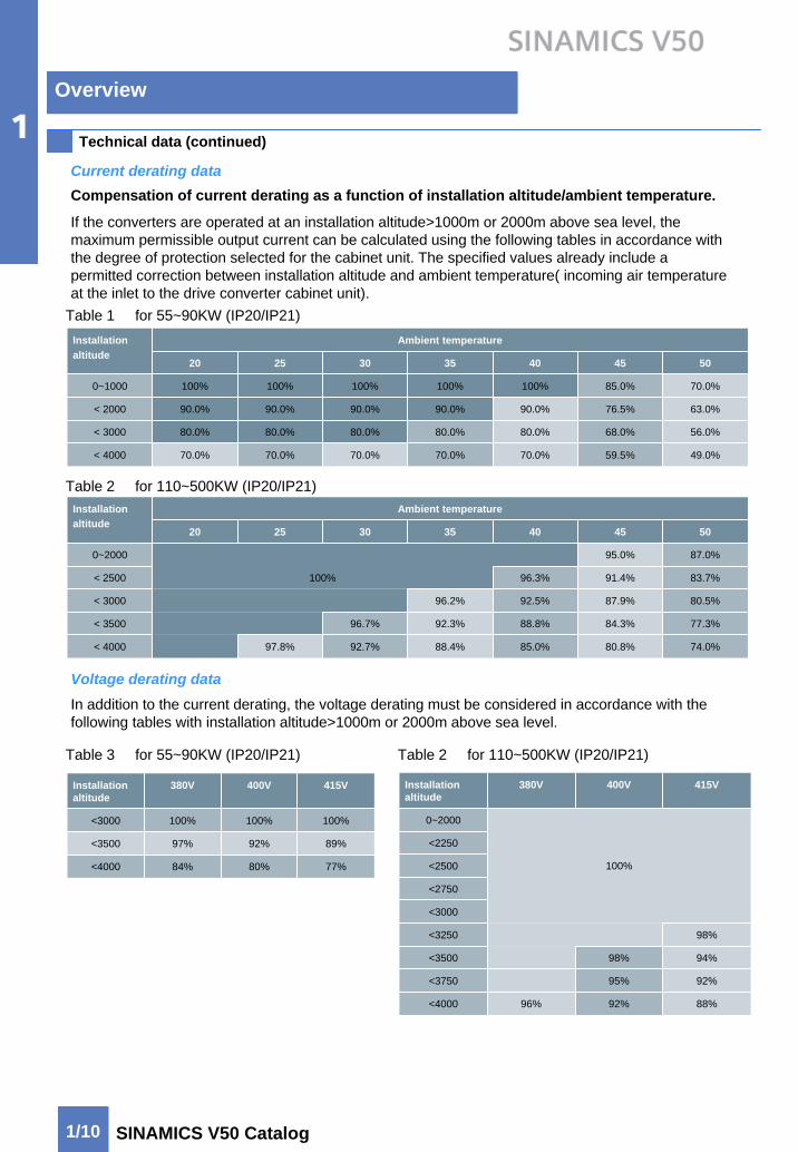
Technical data (continued)
Compensation of current derating as a function of installation altitude/ambient temperature.
If the converters are operated at an installation altitude>1000m or 2000m above sea level, the maximum permissible output current can be calculated using the following tables in accordance with the degree of protection selected for the cabinet unit. The specified values already include a permitted correction between installation altitude and ambient temperature( incoming air temperature at the inlet to the drive converter cabinet unit).
Table 1 for 55~90KW (IP20/IP21)
Current derating data
Table 2 for 110~500KW (IP20/IP21)
Voltage derating dataIn addition to the current derating, the voltage derating must be considered in accordance with the following tables with installation altitude>1000m or 2000m above sea level.
Table 3 for 55~90KW (IP20/IP21) Table 2 for 110~500KW (IP20/IP21)
Ambient temperatureInstallationaltitude
20 25 30 35 40 45 50
0~1000 100% 100% 100% 100% 100% 85.0% 70.0%
< 2000 90.0% 90.0% 90.0% 90.0% 90.0% 76.5% 63.0%
< 3000 80.0% 80.0% 80.0% 80.0% 80.0% 68.0% 56.0%
70.0% 70.0% 70.0% 70.0% 49.0%59.5%< 4000 70.0%
77.3%84.3%88.8%92.3%96.7%< 3500
80.5%87.9%92.5%96.2%< 3000
83.7%91.4%96.3%100%< 2500
87.0%95.0%0~2000
50454035302520
74.0%85.0%92.7% 80.8%97.8%
Ambient temperature
88.4%< 4000
Installationaltitude
77%80%84%<4000
89%92%97%<3500
100%100%100%<3000
415V400V380VInstallation altitude
92%95%<3750
98%<3250
94%98%<3500
<3000
<2750
<2500
88%92%96%<4000
<2250
100%
0~2000
415V400V380VInstallation altitude

Overview
1/11SINAMICS V50 Catalog
Technical data
Overload capacity
The overload capacity of SINAMICS V50 is defined as follows:
Using 500s as duty cycle, overload can be 110% of rated current Ie for 60s.
Converter current
Short-time current
Rated current
EMC guidelines
The electromagnetic compatibility describes – in accordance with the definition of the EMC directive – “the capability of a device to work satisfactorily in the electromagnetic environment without itself causing electromagnetic interference which are unacceptable for other devices present in the environment”. To guarantee that the appropriate EMC directives are observed, the devices must demonstrate a sufficiently high noise immunity, and also the emitted interference must be limited to acceptable values.
The EMC requirements for “Variable-speed drive system” are described in the product standard EN61800-3. A variable-speed drive system (or power drive system, PDS) consists of the drive converter and the electric motor including cables. The driven machine is not part of the drive system.
EN61800-3 defines different limits depending on the location of the drive system, referred to as the first and second environment.
The first environment: Living accommodation or locations where the drive system is directly connected to the public low-voltage network without an intermediate transformer.
The second environment: All locations outside living area. These are basically industrial areas which are powered from the medium-voltage network via their own transformers.
Four difference categories are defined in EN61800-3 Ed.2 depending on the location and the power of the drive:
Category 1: Drive systems for rated voltages<1000V for unlimited use in the first environment.
Category 2: Stationary systems for rated voltages<1000V for use in the second environment. Use in first environment is possible if the system is installed and used by qualified personnel. The warning and installation information supplied by the manufacturer must be observed.
Category 3: Drive systems for rated voltages<1000V for exclusive use in the second environment.
Category 4: Drive systems for rated voltages≥1000V or rated current ≥400A for use in complex systems in the second environment.
The following graphic shows the assignment of the four categories to the first and second environment.
SINAMICS V50 drive converter cabinet units fulfill the requirements for noise immunity defined in EN 61800-3 for the second environment.
Selection and ordering dataSINAMICS V50
Cabinet units2/2
Options2/5

Selection and ordering data
2/2 SINAMICS V50 Catalog
SINAMICS V50 converter cabinet selection data
SINAMICS V50 converter cabinet units selection data
Technical data is applicable to standard unit without options.
Technical data is applicable to standard unit without options.
SINAMICS V50Converter cabinet
Rated input currentA
Rated output currentA
Rated Power
KW
Power loss
KW
Cooling airRequirementm3/s
Sound pressurelevel at 50/60Hz
dB (A)
Line voltage 3AC 380~415V
6SL3710-1BD31-0AA0 110 108 55 1.6 0.15 67/68
6SL3710-1BD31-5AA0 147 147 75 2.1 0.15 67/68
6SL3710-1BD31-7AA0 175 175 90 2.5 0.15 67/68
6SL3710-1BD32-1AA0 233 211 110 2.9 0.17 69/73
6SL3710-1BD32-5AA0 277 252 132 3.8 0.23 69/73
6SL3710-1BD33-0AA0 334 302 160 4.4 0.36 69/73
6SL3710-1BD33-8AA0 396 377 200 5.3 0.36 69/73
6SL3710-1BD34-5AA0 468 446 250 6.4 0.36 69/73
6SL3710-1BD35-7AA0 596 567 315 8.2 0.36 70/73
6SL3710-1BD36-4AA0 676 641 355 8.9 0.78 70/73
6SL3710-1BD37-2AA0 761 725 400 9.6 0.78 70/73
13.1 70/736SL3710-1BD41-0AA0 936 893 500 1.48
13 ~ 161200 x 2000 x 6008604006SL3710-1BD37-2AA0
9 ~ 121200 x 2000 x 6008603556SL3710-1BD36-4AA0
9 ~ 121200 x 2000 x 6008603156SL3710-1BD35-7AA0
5 ~ 8900 x 2000 x 6003902506SL3710-1BD34-5AA0
5 ~ 8900 x 2000 x 6003902006SL3710-1BD33-8AA0
5 ~ 8900 x 2000 x 6003901606SL3710-1BD33-0AA0
5 ~ 8900 x 2000 x 6003201326SL3710-1BD32-5AA0
5 ~ 8900 x 2000 x 6003201106SL3710-1BD32-1AA0
1 ~ 4600 x 2000 x 600240906SL3710-1BD31-7AA0
1 ~ 4600 x 2000 x 600240756SL3710-1BD31-5AA0
1 ~ 4600 x 2000 x 600240556SL3710-1BD31-0AA0
Line voltage 3AC 380V~415V
17 ~ 201600 x 2000 x 60010005006SL3710-1BD41-0AA0
Frame sizeDimension of cabinetW×H×Dmm
Weight
Kg
Rated power
KW
SINAMICS V50Converter cabinet

Selection and ordering data
2/3SINAMICS V50 Catalog
SINAMICS V50 converter cabinet selection data
The table below show the recommended or maximum possible cable connection on the line and motor sides. The recommended cross-sections are based on the listed fuses and single routing of the three-wire cables at an ambition temperature of 40℃.
In the case of different conditions (cable routing, cable grouding, ambition temperature), the configuration instructions for routing the cables must be taken into account.
Power
KWRecommended cross-section
DIN VDE
Maximum conductor cross-section
DIN VDE
Line connectionMounting screw M12
(No. of holes)
Motor connection Cabinet grouding
Recommended cross-section
DIN VDE
Maximum conductor cross-section
DIN VDE
Mounting screw M12
(No. of holes)
Mounting screw M12
(No. of holes)
Comment
Line voltage 3AC 380V~415V
Selection and ordering data
2/4 SINAMICS V50 Catalog
Options
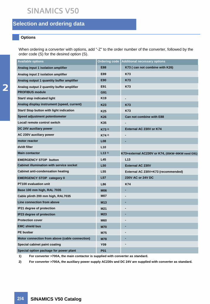
When ordering a converter with options, add ”-Z” to the order number of the converter, followed by the order code (S) for the desired option (S).
Analog input 1 isolation amplifier
PROFIBUS module
Start/ stop indicated light
Analog display instrument (speed, current)
Start/ Stop button with light indication
Speed adjustment potentiometer
Local/ remote control switch
DC 24V auxiliary power
AC 230V auxiliary power
motor reactor
dv/dt filter
Main contactor
EMERGENCY STOP buttonCabinet illumination with service socket
Cabinet anti-condensation heating
PT100 evaluation unit
Base 100 mm high, RAL 7035
Cable plinth 200 mm high, RAL7035
Line connection from above
IP21 degree of protection
IP23 degree of protection
Protection cover
EMC shield bus
PE busbar
Motor connection from above (cable connection)
Special cabinet paint coating
Special option package for power plant
K73 ( can not combine with K26)
-
K73
Can not combine with E88
-
External AC 230V or K74
-
-
K73+external AC230V or K74, (55KW~90KW need G91)
L13
External AC 230V
External AC 230V+K73 (recommended)
K74
-
-
-
-
-
-
-
-
-
Available options Ordering code Additional necessary options
E88
Analog input 2 isolation amplifier K73E89
Analog output 1 quantity buffer amplifier K73E90
Analog output 2 quantity buffer amplifier K73E91
G91
K19
K73K23
K25
K26
K35
K73 2)
K74 2)
L08
L10
L13 1)
L45
L50
L55
L86
M06M07
M13
M21
M23
M60
M70
M75
M78
Y09
P011) For converter >700A, the main contactor is supplied with converter as standard.
2) For converter >700A, the auxiliary power supply AC230v and DC 24V are supplied with converter as standard.
-
EMERGENCY STOP category 0 230V AC or 24V DCL57

Selection and ordering data
2/5SINAMICS V50 Catalog
Options
Option selection Matrix
E GE88~91 Analog input/output isolation amplifierIsolation amplifiers for analog inputs/outputs isolate the different reference potentials of the signals between the unit electronics and the higher-level controller and also increase electrical immunity to interference.
If this option is chosen, the option K73 has to be chosen as well.
E88 Analog input 1 isolation amplifierInput: 0 (4) mA~20mA, or 0V~10V
Output: 0 (4) mA~20mA, or 0V~10V
E89 Analog input 2 isolation amplifierInput: 0 (4) mA~20mA, or 0V~10V
Output: 0 (4) mA~20mA, or 0V~10V
E90 Analog output 1 isolation amplifierInput: 0V~10V, or 0 (4) mA~20mAOutput: 0V~10V, or 0 (4) mA~20mA
E91 Analog output 2 isolation amplifierInput: 0V~10V, or 0 (4) mA~20mAOutput: 0V~10V, or 0 (4) mA~20mA
G91 PROFIBUS moduleFor a complete PROFIBUSconnection with up to12 Mbaud. Remote controlof the inverter is possible withthe PROFIBUS module. Remotecontrol and operation atthe inverter can be combinedusing an operator panelplugged onto the PROFIBUSmodule. The PROFIBUS modulecan be supplied by an external24 V DC power supplyand is thus also active whenthe inverter is disconnectedfrom the power supply.Connection by means of a9-pin Sub-D connector (availableas an option).
KK19 Start/ Stop indicated lightStart (green) and Stop (red) are mounted in the cabinet front door.K23 Analog display instrument (speed, current)Analog meters for speed and current are mounted in the cabinet front door.
1) For converter >700A, L13 need to be selected.

Selection and ordering data
2/6 SINAMICS V50 Catalog
K
K25 Start/ Stop button with light indicationStart (green) and Stop (red) button are mounted in the cabinet front door. These two button can be the local On/Off command source.
K26 Speed adjustment potentiometerSpeed adjustment potentiometer is mounted in the cabinet front door. It can be used as analog speed setpoint.
K35 Local/ remote control switchLocal/ remote control switch switches control mode between local and remote.
L
K73 DC 24V auxiliary powerThe auxiliary power supply provides 24 V DC power for the electronics and inverter options. The auxiliary power supply is fed via the external AC 230V or K74.For converter 400KW~500KW, option K73 is supplied with converter as standard.K74 AC 230V auxiliary powerThe auxiliary power supply is via the mains supply by means of a control transformer.For converter 400KW~500KW, option K73 is supplied with converter as standard.
L08 motor reactormotor reactors limit the capacitive charge/discharge currents of motor supply cables, thus enabling the operation of motors connected via long cable lengths. With motor reactor, the Maximum output frequency is 100Hz.
Notice: L08 can not be used combine with M78 (Motor connection from above).
Cable length should be determined according to the line voltage, the table shows the maximum connectable motor cable lengths, with or without motor reactor.
Selection and ordering data
2/7SINAMICS V50 Catalog
L
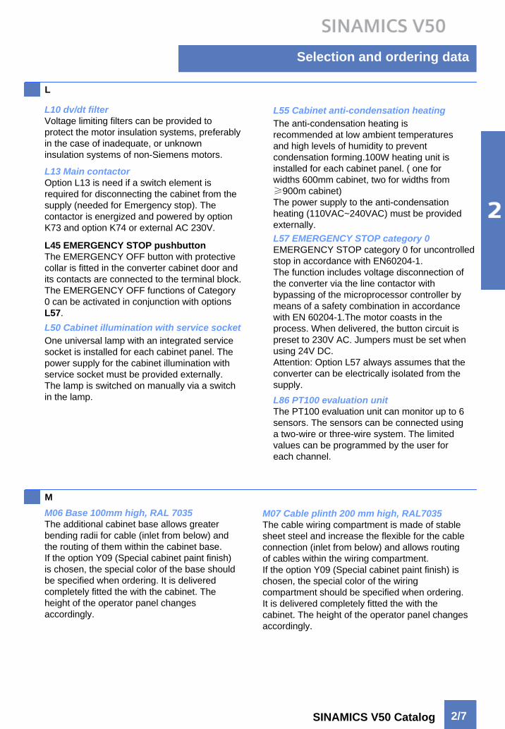
L10 dv/dt filterVoltage limiting filters can be provided to protect the motor insulation systems, preferably in the case of inadequate, or unknown insulation systems of non-Siemens motors.
L13 Main contactorOption L13 is need if a switch element is required for disconnecting the cabinet from the supply (needed for Emergency stop). The contactor is energized and powered by option K73 and option K74 or external AC 230V.
L45 EMERGENCY STOP pushbuttonThe EMERGENCY OFF button with protective collar is fitted in the converter cabinet door and its contacts are connected to the terminal block. The EMERGENCY OFF functions of Category 0 can be activated in conjunction with options L57.L50 Cabinet illumination with service socketOne universal lamp with an integrated service socket is installed for each cabinet panel. The power supply for the cabinet illumination with service socket must be provided externally. The lamp is switched on manually via a switch in the lamp.
L55 Cabinet anti-condensation heatingThe anti-condensation heating is recommended at low ambient temperatures and high levels of humidity to prevent condensation forming.100W heating unit is installed for each cabinet panel. ( one for widths 600mm cabinet, two for widths from ≥900m cabinet)The power supply to the anti-condensation heating (110VAC~240VAC) must be provided externally.
L86 PT100 evaluation unitThe PT100 evaluation unit can monitor up to 6 sensors. The sensors can be connected using a two-wire or three-wire system. The limited values can be programmed by the user for each channel.
MM06 Base 100mm high, RAL 7035The additional cabinet base allows greater bending radii for cable (inlet from below) and the routing of them within the cabinet base.If the option Y09 (Special cabinet paint finish) is chosen, the special color of the base should be specified when ordering. It is delivered completely fitted the with the cabinet. The height of the operator panel changes accordingly.
M07 Cable plinth 200 mm high, RAL7035The cable wiring compartment is made of stable sheet steel and increase the flexible for the cable connection (inlet from below) and allows routing of cables within the wiring compartment.If the option Y09 (Special cabinet paint finish) is chosen, the special color of the wiring compartment should be specified when ordering. It is delivered completely fitted the with the cabinet. The height of the operator panel changes accordingly.
L57 EMERGENCY STOP category 0EMERGENCY STOP category 0 for uncontrolled stop in accordance with EN60204-1.The function includes voltage disconnection of the converter via the line contactor with bypassing of the microprocessor controller by means of a safety combination in accordance with EN 60204-1.The motor coasts in the process. When delivered, the button circuit is preset to 230V AC. Jumpers must be set when using 24V DC.Attention: Option L57 always assumes that the converter can be electrically isolated from the supply.

Selection and ordering data
2/8 SINAMICS V50 Catalog
M PM13 Line connection from aboveThe control cabinet is provided with an additional hood in the case of a line connection from above.
P01 Special option package for power plantSpecially for power plant application includes:
Lamp, button and switch• Start/ stop indicated light• Power supply indicated light• Fault indicated light• Start/ Stop button with light• Testing light button with light• Fault reset button with light• EMERGENCY STOP pushbutton• Local/Remote control switch• Speed reverse switch • Speed adjustment potentiometer
Project• Line connection from above• External power supply AC 230 V• motor reactor• Output switch (motor connection)
Special design • SINAMICS V50 label
Y
Y09 Special cabinet paint coatingThe drive converter cabinet units are colored RAL 7035 as standard. The special color must be specified in plain text when ordering. All RAL colors can be selected which are available as powdered coatings. If options such as cable compartment (M06 or M07), top covers or canopies (M21), hoods (M23) are required for the cabinet, these are provided in the ordered cabinet color.The molded plastic parts (such as ventilation grille) can not be painted.
M21 IP21 degree of protectioncabinet version in IP20, but with additional top cover or canopy. The cabinet height is then increased by 250mm. For transport reason, the top cover or canopy are delivered separately and must be fitted on site. M23 IP23 degree of protectionDrive converter cabinet units with degree of protection IP23 are supplied with additional hoods and plastic ventilation grilles in the air inlet and outlet. The cabinet height is increased by 400mm.For transport reason, the top cover or canopy are delivered separately and must be fitted on site. M60 Protection coverOption M60 provides the protection covers for hazardous voltage area and power block. M70 EMC shield busThe EMC shield bus is used to connect shielded power cables for line and motor infeed cable. M75 PE busbarThe PE busbar is used to run the PE conductor for the supply and motor infeed cables. M78 Motor connection from aboveThe control cabinet is provided with an additional hood in the case of a motor connection from above. Within the hood, there are the connection lugs for the power cable and the cable-clamping bar for the mechanical attachment of the cable, an EMC shield bus and a PE busbar.
Dimension drawingSINAMICS V50
55KW~90KW3/2110KW~250KW3/6315KW~500KW3/10

Dimension drawing
SINAMICS V50 Catalog
Converter cabinet units
Dimension drawing 1: 380v~415V 55KW~90KW
Line and motor connection from below1) The minimum height of the installation room
2) Ventilation grille
3) Air outlet
4) Air inlet
5) Cable routes within the shaded area
6) Main switch, can be locked with normal lock
7a) Line connection terminal
7b) Motor connection terminal
8) Options, degree of protection
9) Degree of protection
IP20
IP21
Option M21
IP23
Option M23
10) Transport parts
* Options are shown in gray.
Degree of protection
3/2

Dimension drawing
3/3SINAMICS V50 Catalog
Converter cabinet units (continued)
Dimension drawing 2: 380v~415V 55KW~90KW
Line and motor connection from below
Degree of protection
1) The minimum height of the installation room
2) Ventilation grille
3) Air outlet
4) Air inlet
5) Cable routes within the shaded area
6) Main switch, can be locked with normal lock
7a) Line connection terminal
7b) Motor connection terminal
8) Options, degree of protection
9) Degree of protection
IP20
IP21
Option M21
IP23
Option M23
10) Transport parts
* Options are shown in gray.
Dimension drawing
3/4 SINAMICS V50 Catalog
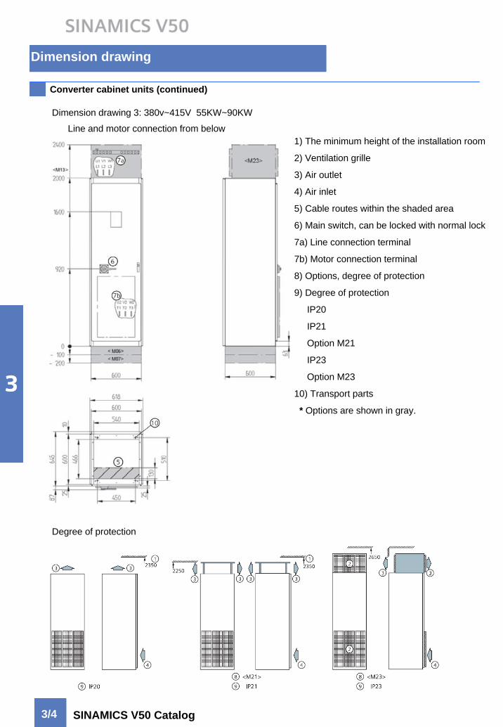
Converter cabinet units (continued)
Dimension drawing 3: 380v~415V 55KW~90KW
Line and motor connection from below1) The minimum height of the installation room
2) Ventilation grille
3) Air outlet
4) Air inlet
5) Cable routes within the shaded area
6) Main switch, can be locked with normal lock
7a) Line connection terminal
7b) Motor connection terminal
8) Options, degree of protection
9) Degree of protection
IP20
IP21
Option M21
IP23
Option M23
10) Transport parts
* Options are shown in gray.
Degree of protection

Dimension drawing
3/5SINAMICS V50 Catalog
Converter cabinet units (continued)
Dimension drawing 4: 380v~415V 55KW~90KW
Line and motor connection from below1) The minimum height of the installation room
2) Ventilation grille
3) Air outlet
4) Air inlet
5) Cable routes within the shaded area
6) Main switch, can be locked with normal lock
7a) Line connection terminal
7b) Motor connection terminal
8) Options, degree of protection
9) Degree of protection
IP20
IP21
Option M21
IP23
Option M23
10) Transport parts
* Options are shown in gray.
Degree of protection

Dimension drawing
3/6 SINAMICS V50 Catalog
Converter cabinet units (continued)
Dimension drawing 5: 380v~415V 110KW~250KW
Line and motor connection from below1) The minimum height of the installation room
2) Ventilation grille
3) Air outlet
4) Air inlet
5) Cable routes within the shaded area
6) Main switch, can be locked with normal lock
7a) Line connection terminal
7b) Motor connection terminal
8) Options, degree of protection
9) Degree of protection
IP20
IP21
Option M21
IP23
Option M23
10) Transport parts
* Options are shown in gray.
Degree of protection
Dimension drawing
3/7SINAMICS V50 Catalog
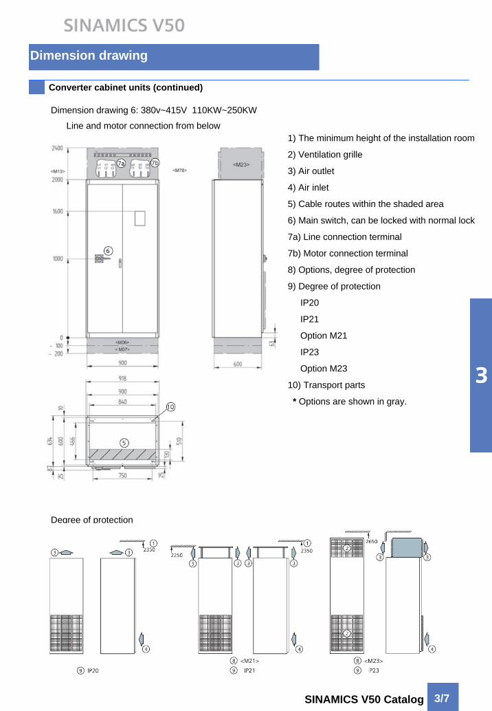
Converter cabinet units (continued)
Dimension drawing 6: 380v~415V 110KW~250KW
Line and motor connection from below1) The minimum height of the installation room
2) Ventilation grille
3) Air outlet
4) Air inlet
5) Cable routes within the shaded area
6) Main switch, can be locked with normal lock
7a) Line connection terminal
7b) Motor connection terminal
8) Options, degree of protection
9) Degree of protection
IP20
IP21
Option M21
IP23
Option M23
10) Transport parts
* Options are shown in gray.
Degree of protection

Dimension drawing
3/8 SINAMICS V50 Catalog
Converter cabinet units (continued)
Dimension drawing 7: 380v~415V 110KW~250KW
Line and motor connection from below1) The minimum height of the installation room
2) Ventilation grille
3) Air outlet
4) Air inlet
5) Cable routes within the shaded area
6) Main switch, can be locked with normal lock
7a) Line connection terminal
7b) Motor connection terminal
8) Options, degree of protection
9) Degree of protection
IP20
IP21
Option M21
IP23
Option M23
10) Transport parts
* Options are shown in gray.
Degree of protection
Dimension drawing
3/9SINAMICS V50 Catalog
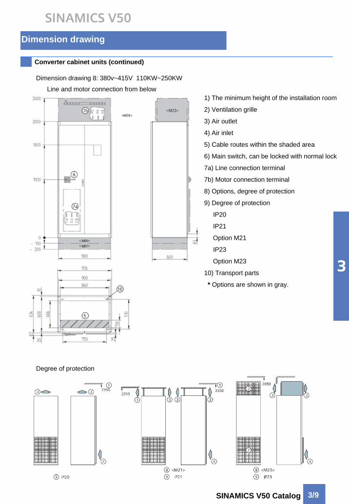
Converter cabinet units (continued)
Dimension drawing 8: 380v~415V 110KW~250KW
Line and motor connection from below1) The minimum height of the installation room
2) Ventilation grille
3) Air outlet
4) Air inlet
5) Cable routes within the shaded area
6) Main switch, can be locked with normal lock
7a) Line connection terminal
7b) Motor connection terminal
8) Options, degree of protection
9) Degree of protection
IP20
IP21
Option M21
IP23
Option M23
10) Transport parts
* Options are shown in gray.
Degree of protection

Dimension drawing
3/10 SINAMICS V50 Catalog
Converter cabinet units (continued)
Dimension drawing 9: 380v~415V 315KW~355KW
Line and motor connection from below1) The minimum height of the installation room
2) Ventilation grille
3) Air outlet
4) Air inlet
5) Cable routes within the shaded area
6) Main switch, can be locked with normal lock
7a) Line connection terminal
7b) Motor connection terminal
8) Options, degree of protection
9) Degree of protection
IP20
IP21
Option M21
IP23
Option M23
10) Transport parts
* Options are shown in gray.
Degree of protection

Dimension drawing
3/11SINAMICS V50 Catalog
Converter cabinet units (continued)
Dimension drawing 10: 380v~415V 315KW~355KW
Line and motor connection from below1) The minimum height of the installation room
2) Ventilation grille
3) Air outlet
4) Air inlet
5) Cable routes within the shaded area
6) Main switch, can be locked with normal lock
7a) Line connection terminal
7b) Motor connection terminal
8) Options, degree of protection
9) Degree of protection
IP20
IP21
Option M21
IP23
Option M23
10) Transport parts
* Options are shown in gray.
Degree of protection
Dimension drawing
3/12 SINAMICS V50 Catalog
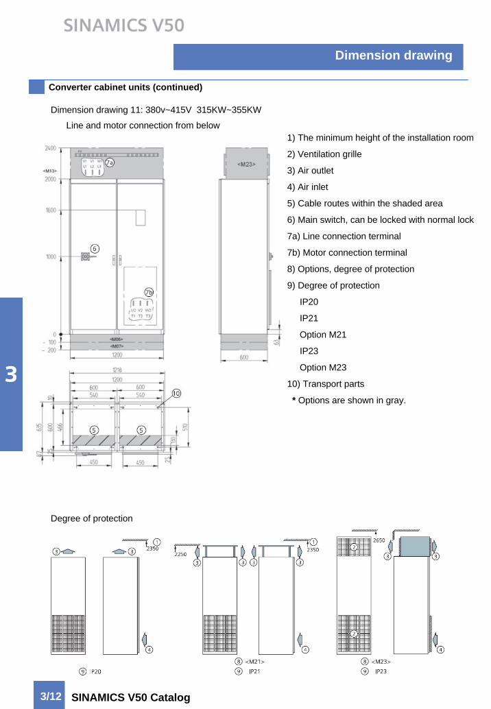
Converter cabinet units (continued)
Dimension drawing 11: 380v~415V 315KW~355KW
Line and motor connection from below1) The minimum height of the installation room
2) Ventilation grille
3) Air outlet
4) Air inlet
5) Cable routes within the shaded area
6) Main switch, can be locked with normal lock
7a) Line connection terminal
7b) Motor connection terminal
8) Options, degree of protection
9) Degree of protection
IP20
IP21
Option M21
IP23
Option M23
10) Transport parts
* Options are shown in gray.
Degree of protection
Dimension drawing
3/13SINAMICS V50 Catalog
Converter cabinet units (continued)
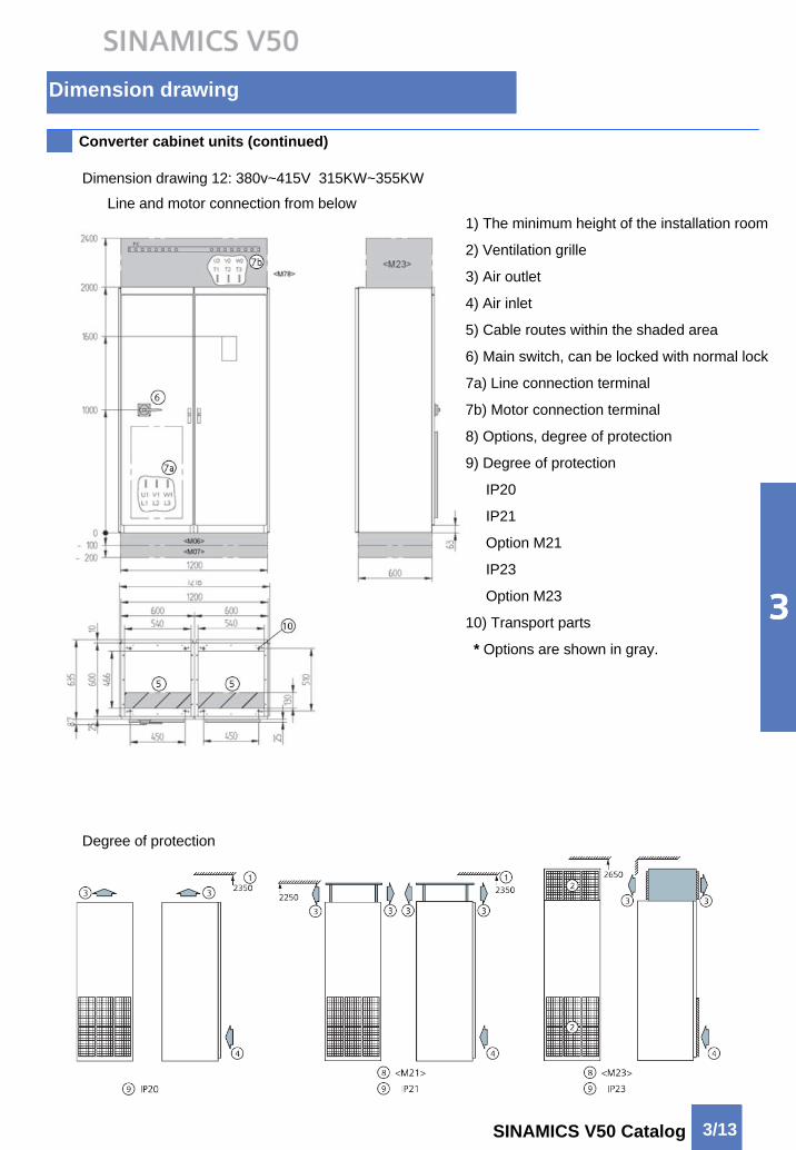
Dimension drawing 12: 380v~415V 315KW~355KW
Line and motor connection from below1) The minimum height of the installation room
2) Ventilation grille
3) Air outlet
4) Air inlet
5) Cable routes within the shaded area
6) Main switch, can be locked with normal lock
7a) Line connection terminal
7b) Motor connection terminal
8) Options, degree of protection
9) Degree of protection
IP20
IP21
Option M21
IP23
Option M23
10) Transport parts
* Options are shown in gray.
Degree of protection
Dimension drawing
3/14 SINAMICS V50 Catalog
Converter cabinet units (continued)
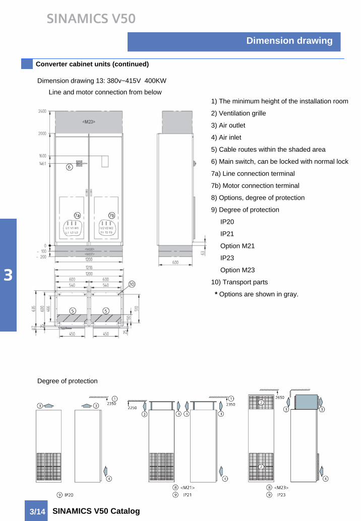
Dimension drawing 13: 380v~415V 400KW
Line and motor connection from below1) The minimum height of the installation room
2) Ventilation grille
3) Air outlet
4) Air inlet
5) Cable routes within the shaded area
6) Main switch, can be locked with normal lock
7a) Line connection terminal
7b) Motor connection terminal
8) Options, degree of protection
9) Degree of protection
IP20
IP21
Option M21
IP23
Option M23
10) Transport parts
* Options are shown in gray.
Degree of protection
Dimension drawing
3/15SINAMICS V50 Catalog
Converter cabinet units (continued)
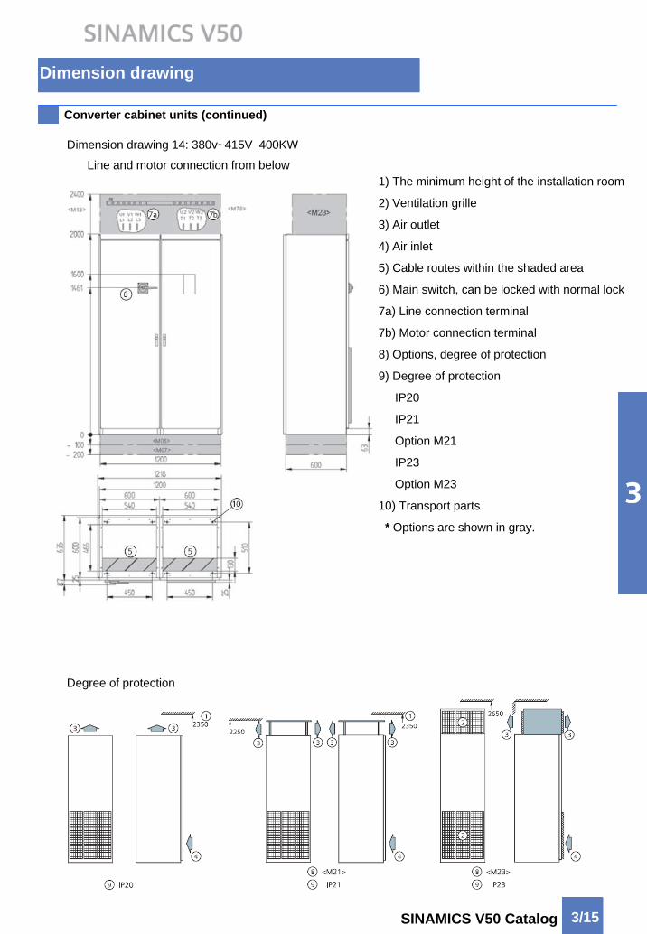
Dimension drawing 14: 380v~415V 400KW
Line and motor connection from below1) The minimum height of the installation room
2) Ventilation grille
3) Air outlet
4) Air inlet
5) Cable routes within the shaded area
6) Main switch, can be locked with normal lock
7a) Line connection terminal
7b) Motor connection terminal
8) Options, degree of protection
9) Degree of protection
IP20
IP21
Option M21
IP23
Option M23
10) Transport parts
* Options are shown in gray.
Degree of protection
Dimension drawing
3/16 SINAMICS V50 Catalog
Converter cabinet units (continued)
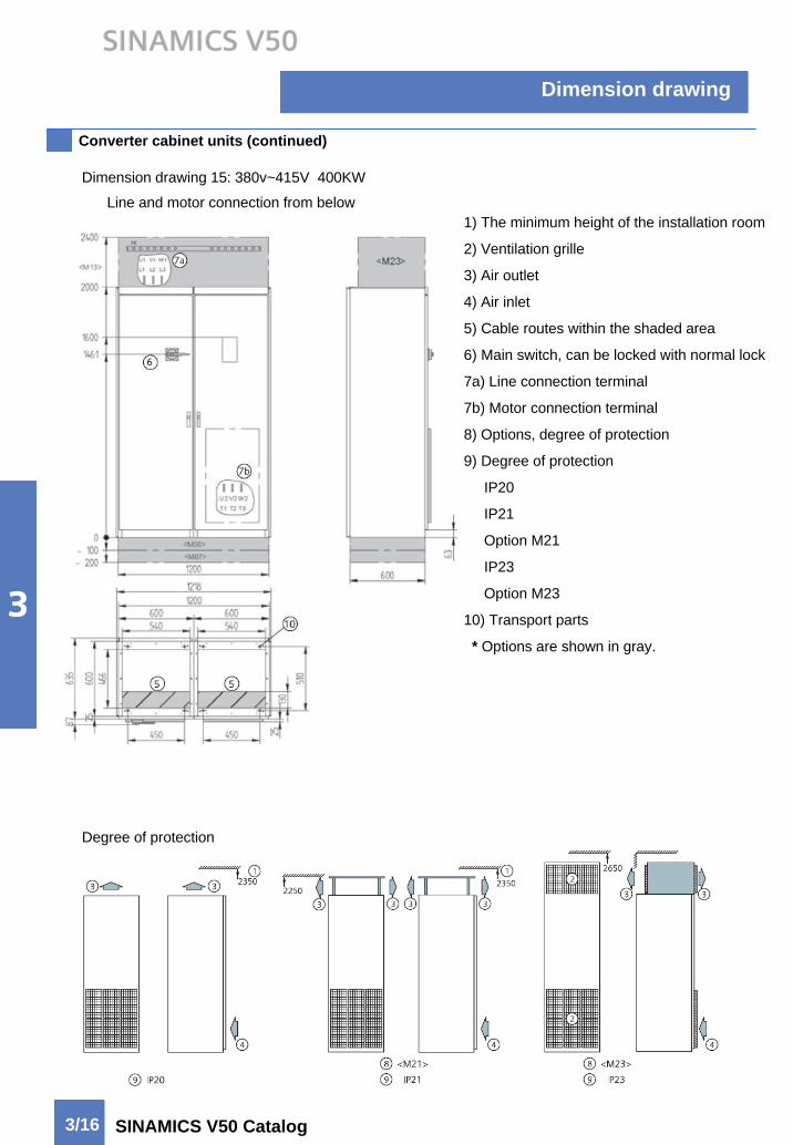
Dimension drawing 15: 380v~415V 400KW
Line and motor connection from below1) The minimum height of the installation room
2) Ventilation grille
3) Air outlet
4) Air inlet
5) Cable routes within the shaded area
6) Main switch, can be locked with normal lock
7a) Line connection terminal
7b) Motor connection terminal
8) Options, degree of protection
9) Degree of protection
IP20
IP21
Option M21
IP23
Option M23
10) Transport parts
* Options are shown in gray.
Degree of protection

Dimension drawing
3/17SINAMICS V50 Catalog
Converter cabinet units (continued)
Dimension drawing 16: 380v~415V 400KW
Line and motor connection from below1) The minimum height of the installation room
2) Ventilation grille
3) Air outlet
4) Air inlet
5) Cable routes within the shaded area
6) Main switch, can be locked with normal lock
7a) Line connection terminal\
7b) Motor connection terminal
8) Options, degree of protection
9) Degree of protection
IP20
IP21
Option M21
IP23
Option M23
10) Transport parts
* Options are shown in gray.
Degree of protection

Dimension drawing
3/18 SINAMICS V50 Catalog
Converter cabinet units (continued)
Dimension drawing 17: 380v~415V 500KW
Line and motor connection from below1) The minimum height of the installation room
2) Ventilation grille
3) Air outlet
4) Air inlet
5) Cable routes within the shaded area
6) Main switch, can be locked with normal lock
7a) Line connection terminal
7b) Motor connection terminal
8) Options, degree of protection
9) Degree of protection
IP20
IP21
Option M21
IP23
Option M23
10) Transport parts
* Options are shown in gray.
Degree of protection

Dimension drawing
3/19SINAMICS V50 Catalog
Converter cabinet units (continued)
Dimension drawing 18: 380v~415V 500KW
Line and motor connection from below1) The minimum height of the installation room
2) Ventilation grille
3) Air outlet
4) Air inlet
5) Cable routes within the shaded area
6) Main switch, can be locked with normal lock
7a) Line connection terminal
7b) Motor connection terminal
8) Options, degree of protection
9) Degree of protection
IP20
IP21
Option M21
IP23
Option M23
10) Transport parts
* Options are shown in gray.
Degree of protection

Dimension drawing
3/20 SINAMICS V50 Catalog
Converter cabinet units (continued)
Dimension drawing 19: 380v~415V 500KW
Line and motor connection from below1) The minimum height of the installation room
2) Ventilation grille
3) Air outlet
4) Air inlet
5) Cable routes within the shaded area
6) Main switch, can be locked with normal lock
7a) Line connection terminal
7b) Motor connection terminal
8) Options, degree of protection
9) Degree of protection
IP20
IP21
Option M21
IP23
Option M23
10) Transport parts
* Options are shown in gray.
Degree of protection
Dimension drawing
3/21SINAMICS V50 Catalog
Converter cabinet units (continued)
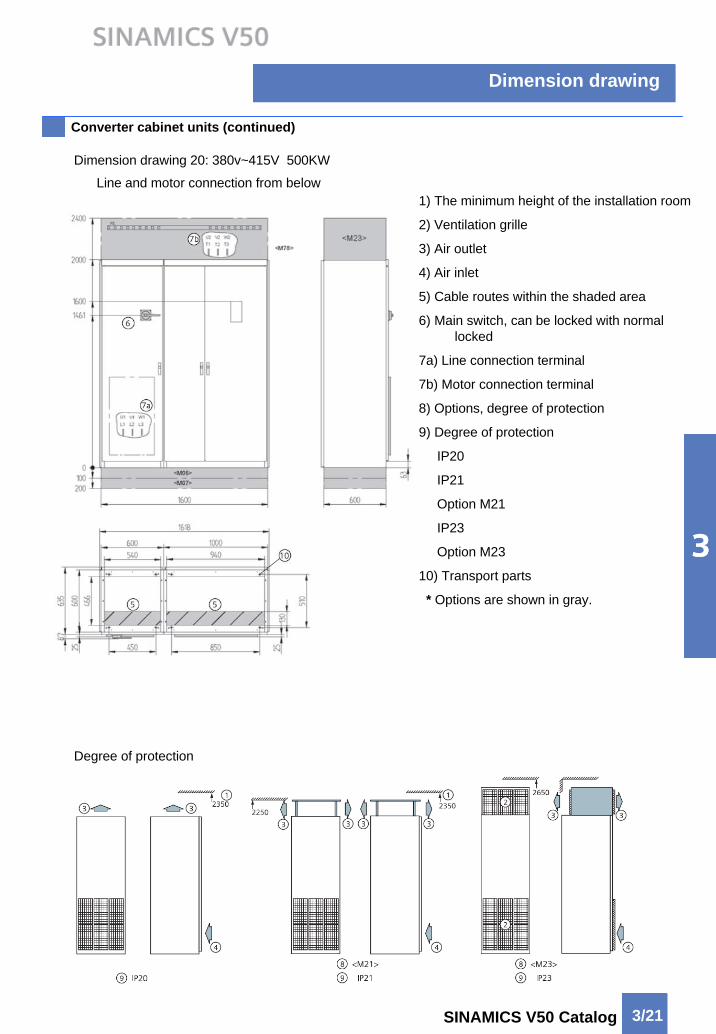
Dimension drawing 20: 380v~415V 500KW
Line and motor connection from below1) The minimum height of the installation room
2) Ventilation grille
3) Air outlet
4) Air inlet
5) Cable routes within the shaded area
6) Main switch, can be locked with normal locked
7a) Line connection terminal
7b) Motor connection terminal
8) Options, degree of protection
9) Degree of protection
IP20
IP21
Option M21
IP23
Option M23
10) Transport parts
* Options are shown in gray.
Degree of protection
Engineering informationSINAMICS V50
4/2
4/8
4/9
Customer’s terminal block
EMERGENCY STOP functions
Line-side components
Load-side components
Max. connectable cable length
Conductor cross-section and connection
Grounding
Motors
Motor Engineering information
Converter and Motor
4/5
4/6
4/7
Dimensioning drives
Engineering information
4/2 SINAMICS V50 Catalog
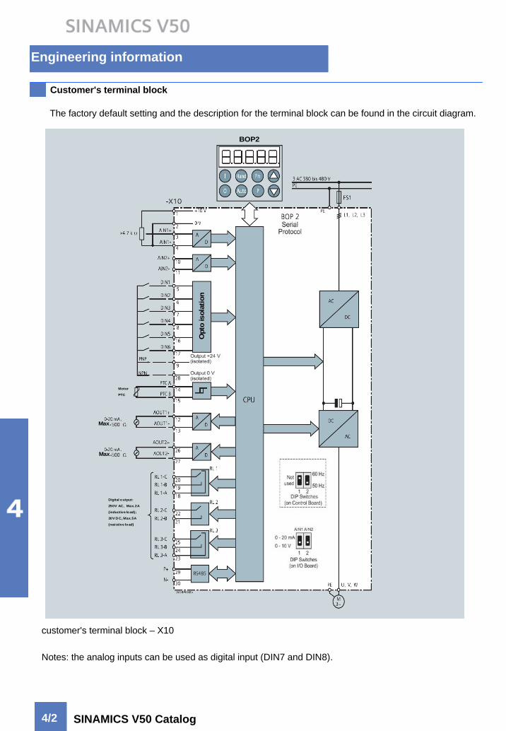
Customer's terminal block
Opt
ois
olat
ion
BOP2
Max.
Max.
Digital o utput:
250V AC, Max.2A
(inductive lo ad);
30V D C, Max.5A
(resistive load)
Motor
PTC
Opt
ois
olat
ion
BOP2
Max.Max.
Max.Max.
Digital o utput:
250V AC, Max.2A
(inductive lo ad);
30V D C, Max.5A
(resistive load)
Motor
PTC
Motor
PTC
customer's terminal block – X10
The factory default setting and the description for the terminal block can be found in the circuit diagram.
Notes: the analog inputs can be used as digital input (DIN7 and DIN8).

Engineering information
4/3SINAMICS V50 Catalog
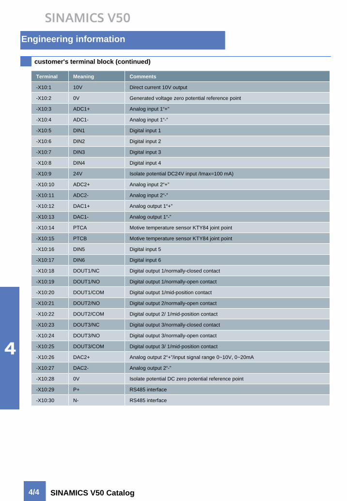
Customer's terminal block (continued)
The analog inputs can be used as digital input (DIN7 and DIN8).
When an analog input is configured as a digital input, the threshold value are as follows:
1.75V DC = off
3.7V DC = on
Engineering information
4/4 SINAMICS V50 Catalog
customer's terminal block (continued)
Terminal Meaning Comments
-X10:1 10V Direct current 10V output
-X10:2 0V Generated voltage zero potential reference point
-X10:3 ADC1+ Analog input 1“+”
-X10:4 ADC1- Analog input 1“-”
-X10:5 DIN1 Digital input 1
-X10:10 ADC2+ Analog input 2“+”
-X10:16 DIN5 Digital input 5
-X10:28 0V Isolate potential DC zero potential reference point
-X10:29 P+ RS485 interface
-X10:17 DIN6 Digital input 6
-X10:18 DOUT1/NC Digital output 1/normally-closed contact
-X10:19 DOUT1/NO Digital output 1/normally-open contact
-X10:20 DOUT1/COM Digital output 1/mid-position contact
-X10:21 DOUT2/NO Digital output 2/normally-open contact
-X10:22 DOUT2/COM Digital output 2/ 1/mid-position contact
-X10:23 DOUT3/NC Digital output 3/normally-closed contact
-X10:24 DOUT3/NO Digital output 3/normally-open contact
-X10:25 DOUT3/COM Digital output 3/ 1/mid-position contact
-X10:26 DAC2+ Analog output 2“+”/input signal range 0~10V, 0~20mA
-X10:27 DAC2- Analog output 2“-”
-X10:11 ADC2- Analog input 2“-”
-X10:12 DAC1+ Analog output 1“+”
-X10:13 DAC1- Analog output 1“-”
-X10:14 PTCA Motive temperature sensor KTY84 joint point
-X10:15 PTCB Motive temperature sensor KTY84 joint point
-X10:6 DIN2 Digital input 2
-X10:7 DIN3 Digital input 3
-X10:8 DIN4 Digital input 4
-X10:9 24V Isolate potential DC24V input /Imax=100 mA)
-X10:30 N- RS485 interface

Engineering information
4/5SINAMICS V50 Catalog
EMERGENCY STOP functions
To achieve this, the drives can be roughly divided into the following group.
Case A:
Drives that are quickly braked to zero speed by the connected load when they are shut down.
Typical example: pumps
For these, an EMERGENCY STOP with category 0 is sufficient.
Case B:
Drives with larger rotating masses that are braked to zero seed by the connected load when they are shut down.
Typical example: fans
For these, an EMERGENCY STOP with category o is sufficient if the coasting time can be tolerated. If, however, a shutdown within a specific time is required for the EMERGENCY STOP case, a category 1 EMERGENCY STOP may be required. In certain circumstances this can require a braking facility, even when this is not required for the actual drive application.
Notes:
For SINAMICS V50, a EMERGENCY STOP with category 0 is sufficient.
EMERGENCY STOP functions may be essential for certain drive applications. In accordance with EN 60204, an EMERGENCY STOP must be designed as a category 0 or category 1 stop.
Stop of category 0:
Uncontrolled shutdown by immediately switching off the power supply. Motor coasts. This corresponds to immediate stopping of the inverter, in association with intrinsically-safe disconnection of the main contactors or – for greater power ranges –of the circuit breaker.
Stop of category 1:
Controlled shutdown, where the power supply is retained until standstill is reached. This can be implemented by means of a rapid stop in association with intrinsically-safe disconnection of the main contactors or the circuit breaker.
Comment:Only a category 0 stop is sensible for converters that do not have braking facilities. An EMERGENCY STOP with a category 1 stop generally requires a braking facilities (braking unit or converter with regenerative feedback).
The category selection must be based on the risk evaluation of the drive unit.
Engineering information
4/6 SINAMICS V50 Catalog
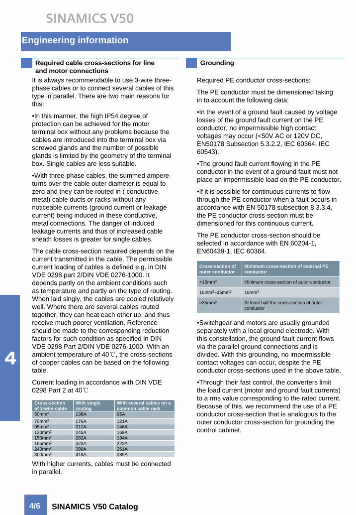
Required cable cross-sections for line and motor connections
It is always recommendable to use 3-wire three-phase cables or to connect several cables of this type in parallel. There are two main reasons for this:
•In this manner, the high IP54 degree of protection can be achieved for the motor terminal box without any problems because the cables are introduced into the terminal box via screwed glands and the number of possible glands is limited by the geometry of the terminal box. Single cables are less suitable.
•With three-phase cables, the summed ampere-turns over the cable outer diameter is equal to zero and they can be routed in ( conductive, metal) cable ducts or racks without any noticeable currents (ground current or leakage current) being induced in these conductive, metal connections. The danger of induced leakage currents and thus of increased cable sheath losses is greater for single cables.
The cable cross-section required depends on the current transmitted in the cable. The permissible current loading of cables is defined e.g. in DIN VDE 0298 part 2/DIN VDE 0276-1000. It depends partly on the ambient conditions such as temperature and partly on the type of routing. When laid singly, the cables are cooled relatively well. Where there are several cables routed together, they can heat each other up, and thus receive much poorer ventilation. Reference should be made to the corresponding reduction factors for such condition as specified in DIN VDE 0298 Part 2/DIN VDE 0276-1000. With an ambient temperature of 40℃, the cross-sections of copper cables can be based on the following table.
Current loading in accordance with DIN VDE 0298 Part 2 at 40℃
Grounding
Required PE conductor cross-sections:
The PE conductor must be dimensioned taking in to account the following data:
•In the event of a ground fault caused by voltage losses of the ground fault current on the PE conductor, no impermissible high contact voltages may occur (<50V AC or 120V DC, EN50178 Subsection 5.3.2.2, IEC 60364, IEC 60543).
•The ground fault current flowing in the PE conductor in the event of a ground fault must not place an impermissible load on the PE conductor.
•If it is possible for continuous currents to flow through the PE conductor when a fault occurs in accordance with EN 50178 subsection 8.3.3.4, the PE conductor cross-section must be dimensioned for this continuous current.
The PE conductor cross-section should be selected in accordance with EN 60204-1, EN60439-1, IEC 60364.
•Switchgear and motors are usually grounded separately with a local ground electrode. With this constellation, the ground fault current flows via the parallel ground connections and is divided. With this grounding, no impermissible contact voltages can occur, despite the PE conductor cross-sections used in the above table.
•Through their fast control, the converters limit the load current (motor and ground fault currents) to a rms value corresponding to the rated current. Because of this, we recommend the use of a PE conductor cross-section that is analogous to the outer conductor cross-section for grounding the control cabinet.
With higher currents, cables must be connected in parallel.
Cross-section of 3-wire cable
With single routing
With several cables on a common cable rack
50mm2 138A 95A121A
95mm2 212A 146A120mm2 245A 169A150mm2 282A 194A185mm2 323A 222A240mm2 380A 261A
289A
70mm2 176A
300mm2 418A
Cross-section of outer conductor
Minimum cross-section of external PE conductor
<16mm2 Minimum cross-section of outer conductor
16mm2~35mm2 16mm2
>35mm2 At least half the cross-section of outer conductor

Engineering information
4/7SINAMICS V50 Catalog
Line-side components
Line fuses
In SINAMICS V50, the SIEMENS fuses (3NA3) are installed as standard for protecting the line side of the converter.
•Superfast
•Low arc voltage
•Improved current limiting
Line reactor
A line reactor is required for high system short-circuit power, partly to protect the converter against excessive harmonic currents, and thus against overload, and partly to limit the harmonic effects on the system to the permissible values. The harmonic current are limited by the complete inductance comprising the line reactor and main power input inductance.
The SINAMICS V50 cabinet units are equipped with a 2% line reactor as standard.
Load-side componentsmotor reactor (L08)
IGBT-converter switching frequencies result in high voltage rises dv/dt at the converter output. If long motor cables are used, this leads to an additional current load on the converter due to capacitive charge/discharge currents.
In addition to, the high voltage rises, and the resulting voltage peaks at the motor terminals, cause the motor’s electrical winding load to increase in comparison to direct on-line operation.
The motor reactor (L08) can limit the voltage rise dv/dt and the voltage peak at the motor terminal.
dv/dt filter plus VPL (L10)
The dv/dt filter plus VPL is used for the non-SIEMEN motors which the voltage endurance of the insulation system is unknown or insufficient.
The dv/dt filter plus VPL limit the rate of voltage rise to <500V/µs and the typical voltage peaks at rated line voltages to the thevalue <1000V.
Max. connectable motor cable length
Refer to page 2/6
Connection point of converter
Main power input inductance
Line reactor
Line Converter

Engineering information
4/8 SINAMICS V50 Catalog
Dimensioning drives
Typical curve of the permisible torque with self-ventilated motors (e.g. 1LA) with a rated frequency of 50Hz
Drives with quadratic load torque
Drives with a quadratic load toque(M~n2), such as drives for pumps and fans, require the full torque at the rated speed.
Increased starting torques or high load surges do not usually occur. It is therefore unnecessary to provide a higher overload capability for the converter.
The following applies to selection of a suitable converter for drives with a quadratic load torque:
The rated current of the converter must be at least as large as the motor current at full torque in the required load point.
When using standard 1LG4/1LG6 and 1LA8 motors, these motors can also be loaded with the full rated power even in converter mode. They are then utilized to full advantage in accordance with temperature class F. However, if the motors may only be utilized to full advantage in accordance with temperature class B, the motor power must be reduced by 10%.
Rated current-permissible and non-permissible motor/converter combinations
Drives with a quadratic load torque(M~n2),such as drives for pumps and fans, require the full torque at the rated speed.The rated current of the converter must be at least as large as the motor current at full torque in the required load point.
Motor rated current greater than converter rated current
If a motor is used whose rated current is greater than the rated converter current, this means that the motor can only be operated at partial load. The following limit must be observed.
The maximum possible converter current (overload current) should be greater than or equal to the rated current of the connected motor.
If this dimensioning is not observed, current peaks which can either lead to switching-off or can cause a continuous reduction in power by the internal protection circuit can occur as a result of the low leakage inductance of larger motors.
Rated motor current much smaller than converter rated current
The rated motor current for the sensorless Vector Control used must be at least ¼ of the rated converter current. With smaller motor currents, operation using the V/f control mode is possible.

Engineering information
4/9SINAMICS V50 Catalog
Motors
Other motorsIn addition to the 1LA and 1LG motors, the 1PH7/1PL6 compact asynchronous motors can also be used. These are recommended for:Large speed range with high maximum speeds.Limited mounting space.1PH7/1PL6 motors are on average 1 to 2 shaft heights smaller than comparable standard asynchronous motors with the same rated output.
Line voltages>500V for 1LA/1LG motorsThe standard insulation of the 1LA and 1LG motors is designed such that operation without limitation is only possible on the converter at line voltages of 500V+10%.At higher voltages, the motor require greater insulation resistance.1LA8/1PQ8 and 1LG6 motors are also available with a higher insulation resistance for converter-fed operation with voltages up to 690V;no filters are required in the case. These motors are identified by an “M” as the 10th digit of the Order No.(e.g.1LA8315-2PM).With the reinforced insulation system, there is less space in the grooves for the same number of windings compared to the normal version, which slightly reduces the rated output of these motors.
Motor protectionA motor protection function can be implemented using the I2t detection present in the converter software.If precise motor protection is required, this can be afforded by direct temperature measurement using KTY84 sensors or PTC thermistors in the motor winding.When using the KTY84 sensors, motor option A23 must be specified when ordering 1LA8 and 1LG4/1LG6 motors. With 1PH7 and 1PL6 motors, the sensors are fitted as standard.If PTC thermistors are required, motor option A11 or A12 must be specified when ordering 1LG4/1LG6 motors. With 1LA8/1PQ8 motors, the sensors are fitted as standard.The KTY84 sensor and PTC thermistor can be evaluated by connecting.• to the customer's terminal block in the converter (SINAMICS G150)• to the –X41 terminal of the Power Module (SINAMICS G130)
The 1LG4/1LG6 and 1LA8 motors are self-ventilated motors with IP55 degree of protection.Both the internal and external fans (which are fitted in each motor) have a fixed connection to the shaft.The cooling effect is therefore directly dependent on the motor speed.
1LA and 1LG motorIt is generally recommendable to use the standard Siemens motors 1LA and 1LG.With regard to the voltage stress, the standard insulation of the motors is designed such that operation on the converter is possible without limitation at voltages V≤500V.For detailed data about motor types, please refer to catalog M11.
Self-ventilated, IP55 (1LG4/1LG6 and 1LA8)
Engineering information
4/10 SINAMICS V50 Catalog
Motors (continued)
PT100 temperature sensors (resistance thermometers) are alternatively possible for the 1LA8 and 1LG4/1LG6 motors for monitoring the motor winding temperature. When ordering the motor, either option A60(3×PT100) or A61(6×PT100) must be selected.A separate evaluation unit is available (option L86) for evaluation of the PT100 temperature sensors in the SINAMICS G150 drive converter cabinet unit.
Bearing currentsIn order to apply currents to the motor which are sinusoidal as far as possible (smooth running, oscillation torques stray losses), a high clock frequency is required for the converter’s output voltage. The rated (Very steep) switching edges of the converter output voltage (and also, therefore, of the common-mode voltage) cause correspondingly high capacitive currents and voltages on the machine’s internal capacitances.This physical effect, which occurs in isolated cases, has mostly been observed in connection with large motors.
The most important measures for reducing bearing currents:
• Insulated motor bearing at the non-drive end. The insulated bearing is standard for all 1LA8 motors designated for converter operation.
• Use of motor reactors (option L08)
Operation of motors with type of protection ”d”1MJ asynchronous motors can be connected as explosion-proof motors with flameproof enclosure EEx de llC both to the line and the converter.In accordance with the test guidelines, the motors of the 1MJ series must be equipped with PTC thermistors.If 1MJ motors are connected to converters, their maximum permissible torque must be reduced, depending on the load characteristic, when utilized in accordance with temperature class B, just like the motors of the 1LA series with the same power.1MJ motors have a terminal box with increased safety EEx ell as standard. No.(e.g.1LA8315-2PM).

AppendixSINAMICS V50
5/2 Environment, resourcesand recycling
5/3 ISO 9001, ISO 14001

Appendix
5/2 SINAMICS V50 Catalog
Environment, resources and recycling
Siemens AG feels a responsibility to play a role in protecting our environment and saving our valuable natural resources. This is true for both our production and our products. Even during development, we consider any possible environmental impact of future products/systems. Our aim is to prevent harmful environmental effects or at least to reduce them to an absolute minimum –beyond present regulations and legislation.
The most important activities for protecting our environment are as follows:
We are constantly endeavoring to reduce the environmental impact of our products as well as their consumption of energy and resources over and above the statutory environmental protection regulations.
We take every possible step to prevent damage to the environment.
Environmental impact is assessed and considered at the earliest possible stage of product and process planning.
Our optimized environmental management strategy ensures that our environmental policy is put into practice effectively. The necessary technical and organizational procedures are reviewed at regular intervals and continuously updated.
An awareness for environmental problems is expected of all our employees. Establishing and furthering a sense of responsibility for the environment on all levels represents a permanent challenge for the corporate management.
We urge our business partners to act according to the same environmental principles as ourselves. We cooperate with the responsible public authorities.
We inform interested members of the public about the consequences of our corporate policies for the environment as well as our achievements to the benefit of the environment.
Our complete documentation is printed on chlorinefree bleached paper.

Appendix
5/3SINAMICS V50 Catalog
ISO 9001, ISO 14001