single buoy mooring system for handling...
TRANSCRIPT

Single Buoy Mooring System for Handling Oil

SPM Terminals at Vadinar
SPM I
SPM II6.3 km
2.1 km5.3 km
5.7 km
VADINAR
JAMNAGAR SURENDRANAGAR
VIRAMGAM
RAJKOT
SIDHPUR
ABUROADKOT
KANTALIYA SENDRA
RAMSAR
CHAKSU – 6 tanks
REWARI
MATHURA
PANIPAT
MATHURA REFINERY
Tank Farm – 9 tanks
Tank Farm – 13 tanks
GUJARAT REFINERY
Pipeline dia from both SPMsto tank farm at Vadinar is 42”
BAREJA
MainlineLoop Line
Single Point Mooring (SPM)What is an SPM?
A complete, self-contained single point offshore terminal facility which provides the means for both mooring and transferring cargo of very large crude oil carriers (VLCC) or floating offshore facilities.
Why an SPM is required?VLCC and ULCC have significant cost-advantages, they need very high draft (more than 20 metres) for movement which is mostly not available near shores. SPM systems are regarded as instant port since they can be installed in deeper areas without any need for construction of jetties.SPM system facilitate faster turnaround of vessels.When production facilities are into deep sea, an SPM is best wayfor cargo transfers via vessels.

Single Point Mooring : FeaturesSalient Features of an SPM System• All SPMs moor a vessel to a single point and allow the vessel to
weathervane about that point, in response to dynamic sea environment of varying sea current and wind.
• SPM systems are designed not to be rigid and contains energy absorption means such as stretchable mooring ropes and anchor chains catenaries.
• All SPMs have a floating buoy anchored to seabed through anchor chains secured on piles. This buoy has a floating hose system for cargo transport, comprising of floating hoses and sub-sea hoses. The floating hoses connect between the buoy and the vessel whereas the sub-sea hoses connect between buoy and the sub-sea pipeline.

Types of Single Point Mooring SystemsTypes of Single Point Mooring Systems
CALM (Catenary Anchor Leg Mooring)• It consists of a buoy anchored by 4 or more chains extending in
catenaries to anchor points on sea floor. SALM (Single Anchor Leg Mooring)
• It consists of a buoy which is anchored to a base on sea floor through a pre-tensioned single anchor leg consisting of a pipe riser pivoted on universal joint and a short anchor chain with a chainswivel.
VALM (Vertical Anchor Leg Mooring)• It consists of a buoy with 3 or more vertical pre-tensioned chains
anchored on seabed.SPMT (Single Point Mooring Tower)
• It consists of a rigid structure erected on seabed and extended uptoabove water surface with a mounted turret on a swivel.

SPM : An Overview
SALM Buoy
Chain
Chain Universal Joint
Swivel
Mooring Base
Riser Universal Jt.Pipeline on Sea-bed
VALM Buoy
Pre-tensioned Chains
Sea-bed Anchor Pile
Swivel
Platform
Riser
Single Point Mooring Tower
Sub-sea line
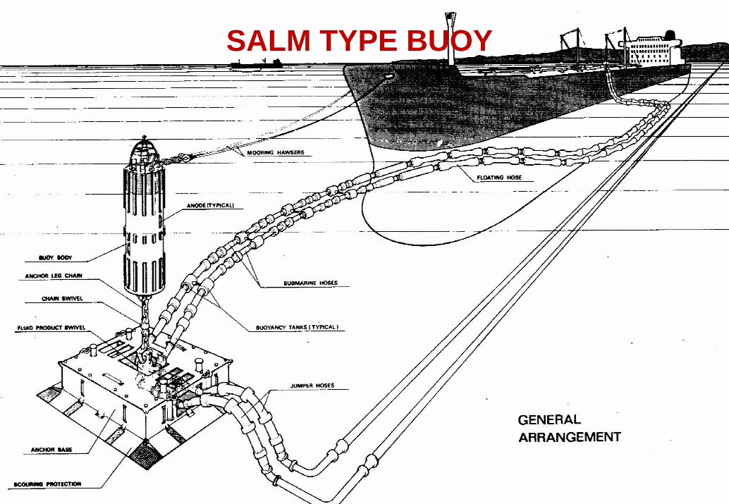
SALM TYPE BUOY
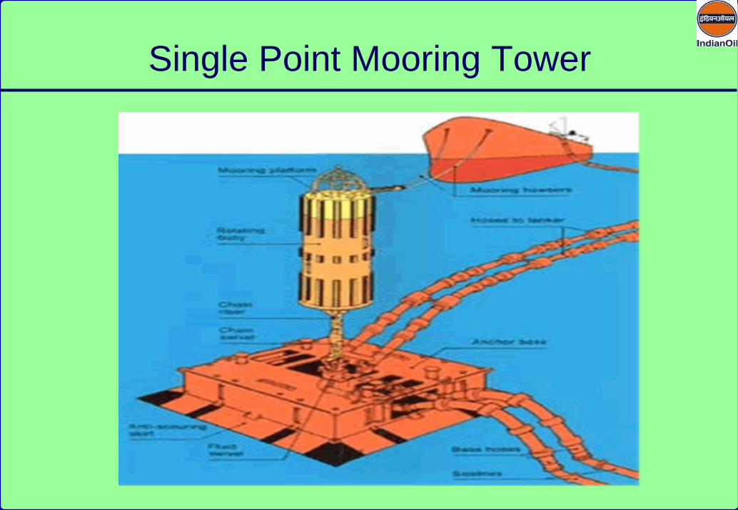
Single Point Mooring Tower
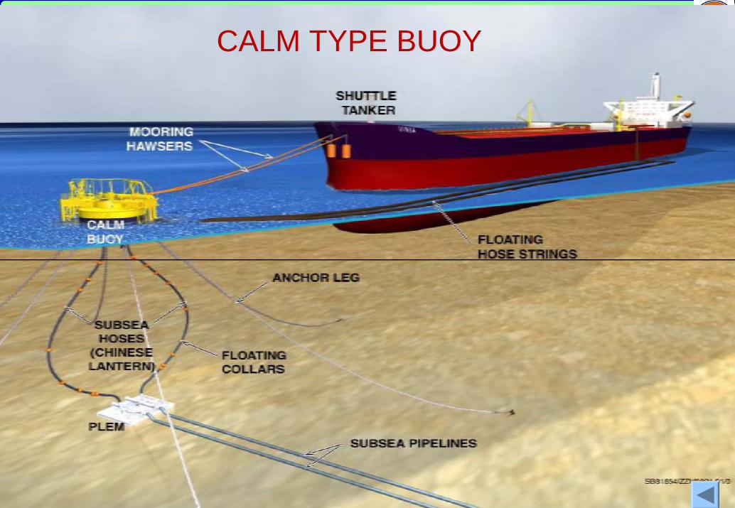
CALM TYPE BUOY
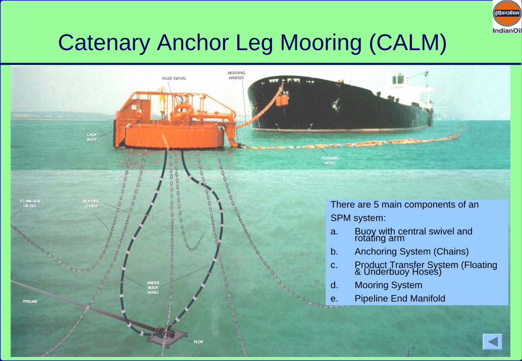
Catenary Anchor Leg Mooring (CALM)
There are 5 main components of an SPM system:a. Buoy with central swivel and
rotating armb. Anchoring System (Chains)c. Product Transfer System (Floating
& Underbuoy Hoses)d. Mooring Systeme. Pipeline End Manifold

Buoy
Anchoring System (Buoy Mooring system)
Mooring System (Tanker Mooring system)
Product Transfer system
Support & Safety Equipments
Major Components of an SPM System
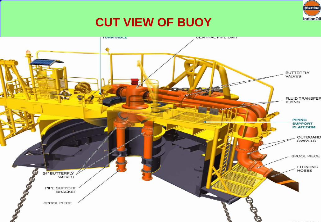
CUT VIEW OF BUOY

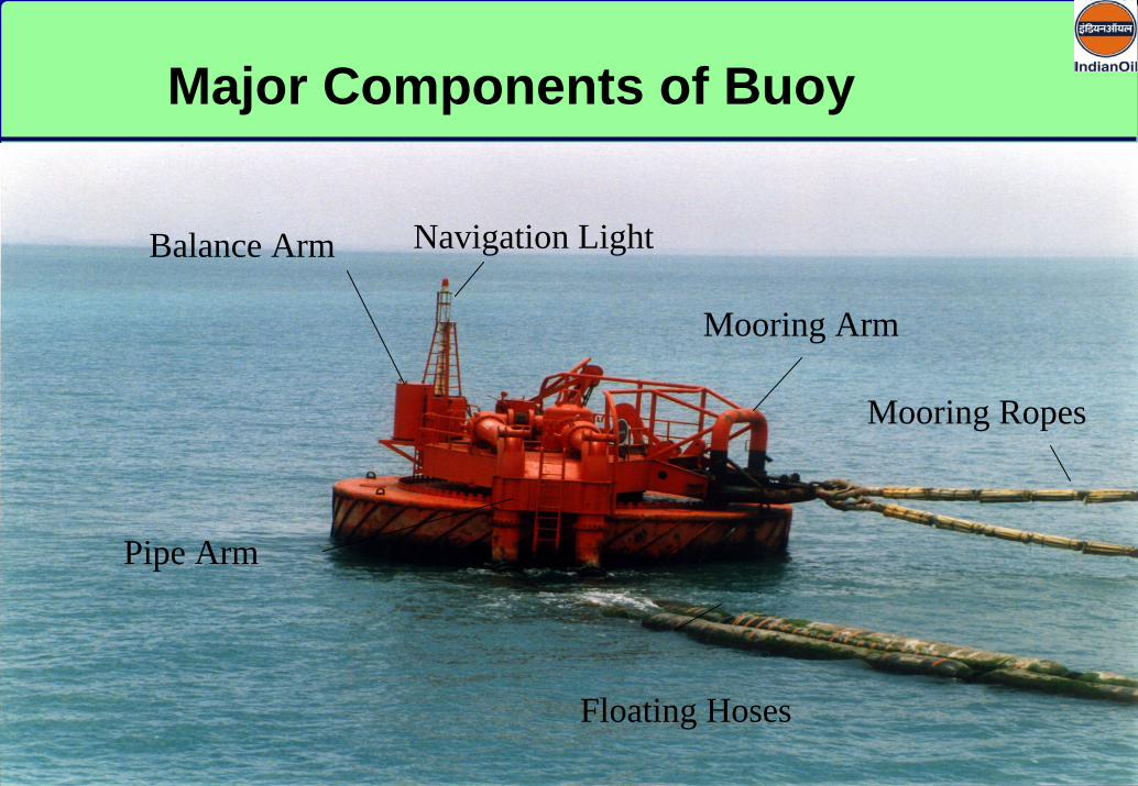
Major componentsFloating BuoyTurntablea) Mooring Armb) Pipe Armc) Balance ArmPDU
Major Components of Buoy

Floating Hoses
Mooring Ropes
Pipe Arm
Mooring Arm
Balance Arm Navigation Light
Major Components of Buoy
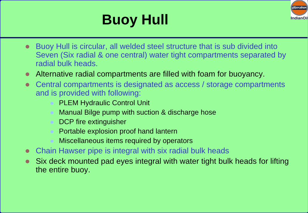
Buoy Hull is circular, all welded steel structure that is sub divided into Seven (Six radial & one central) water tight compartments separated by radial bulk heads.Alternative radial compartments are filled with foam for buoyancy.Central compartments is designated as access / storage compartments and is provided with following:
PLEM Hydraulic Control UnitManual Bilge pump with suction & discharge hoseDCP fire extinguisherPortable explosion proof hand lanternMiscellaneous items required by operators
Chain Hawser pipe is integral with six radial bulk heads Six deck mounted pad eyes integral with water tight bulk heads for lifting the entire buoy.
Buoy Hull
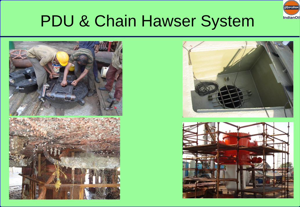
PDU & Chain Hawser System

Turn table on Central Swivel BearingTurn table rotates on central bearing. Wear and tear due to rotation of turn table is less. However, if bearing fails, insitu replacement is not possible. Requires to be changed during dry dock only.
Turn table on Bogey WheelsTurn table is mounted on bogey wheels moving on lower deck of Buoy.Due to wear on bogey wheels, replacement of the same are required at frequent intervals. Wear on buoy body necessitates dry docking at frequent intervals.
Turn table on Wheels & Rail TrackTurn table is mounted on wheels moving on rail track which is positioned on the deck of Buoy.
Types of Turn table
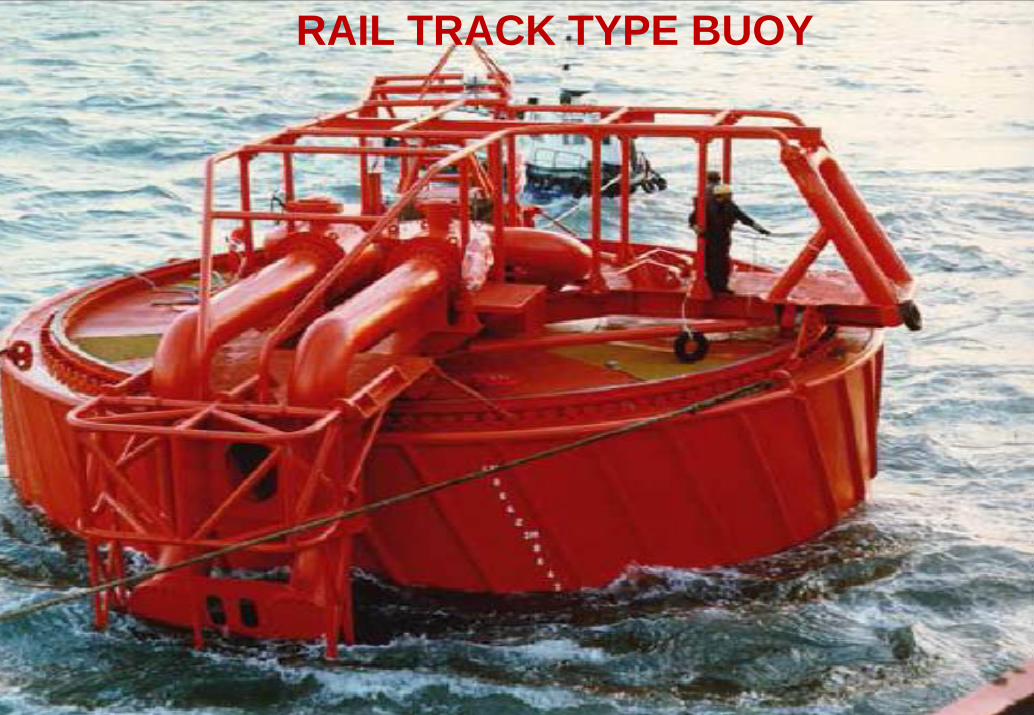
RAIL TRACK TYPE BUOY

RAIL TRCAK & MAIN BERING TYPE BUOYS
RAIL TRACK & MAIN BEARING TYPE BUOYS
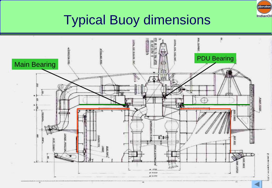
Typical Buoy dimensions
Main BearingPDU Bearing

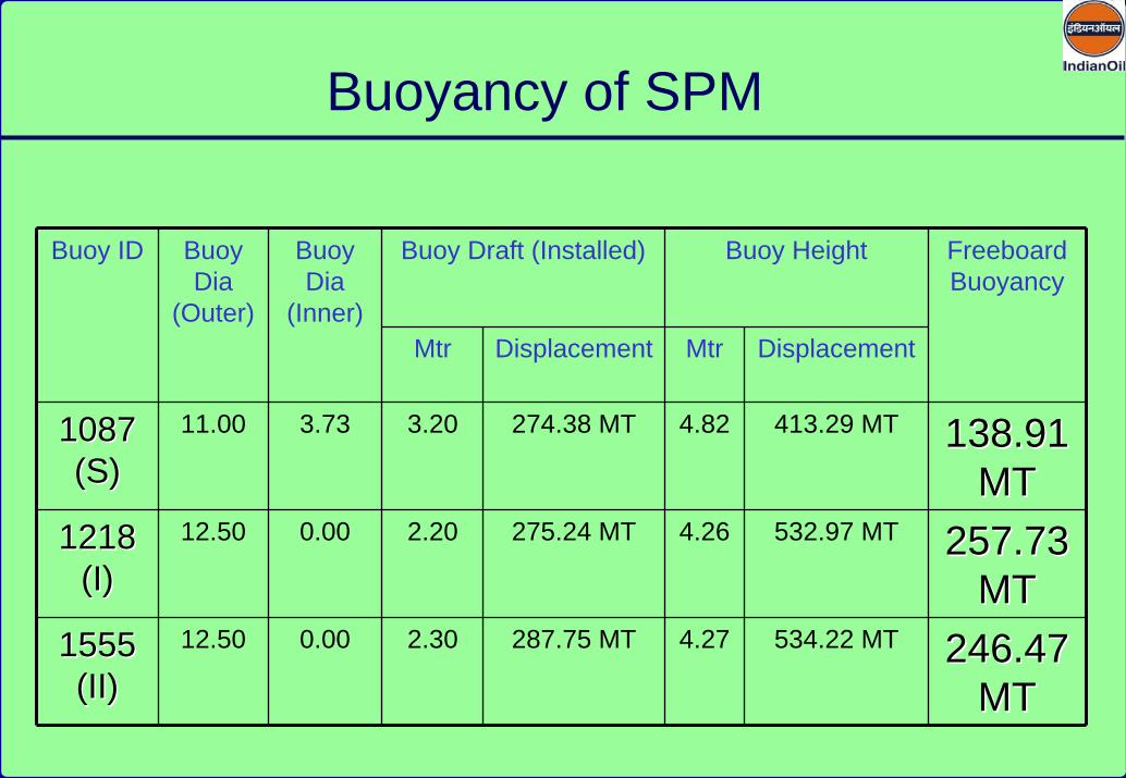
Buoyancy of SPM
Buoy Draft (Installed) Buoy HeightBuoy ID Buoy Dia
(Outer)
Buoy Dia
(Inner)Mtr Displacement Mtr Displacement
Freeboard Buoyancy
1087 1087 (S)(S)
11.00 3.73 3.20 274.38 MT 4.82 413.29 MT 138.91 138.91 MTMT
1218 1218 (I)(I)
12.50 0.00 2.20 275.24 MT 4.26 532.97 MT 257.73 257.73 MTMT
1555 1555 (II)(II)
12.50 0.00 2.30 287.75 MT 4.27 534.22 MT 246.47 246.47 MTMT


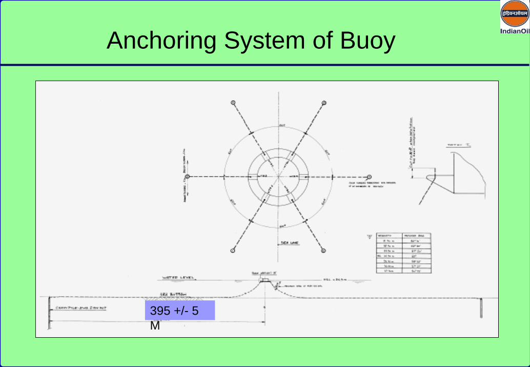
395 +/- 5 M
Anchoring System of Buoy

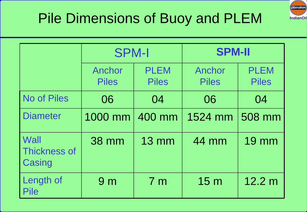
SPM-I SPM-IIAnchor Piles
PLEM Piles
Anchor Piles
PLEM Piles
No of Piles 06 04 06 04Diameter 1000 mm 400 mm 1524 mm 508 mm
Wall Thickness of Casing
38 mm 13 mm 44 mm 19 mm
Length of Pile
9 m 7 m 15 m 12.2 m
Pile Dimensions of Buoy and PLEM

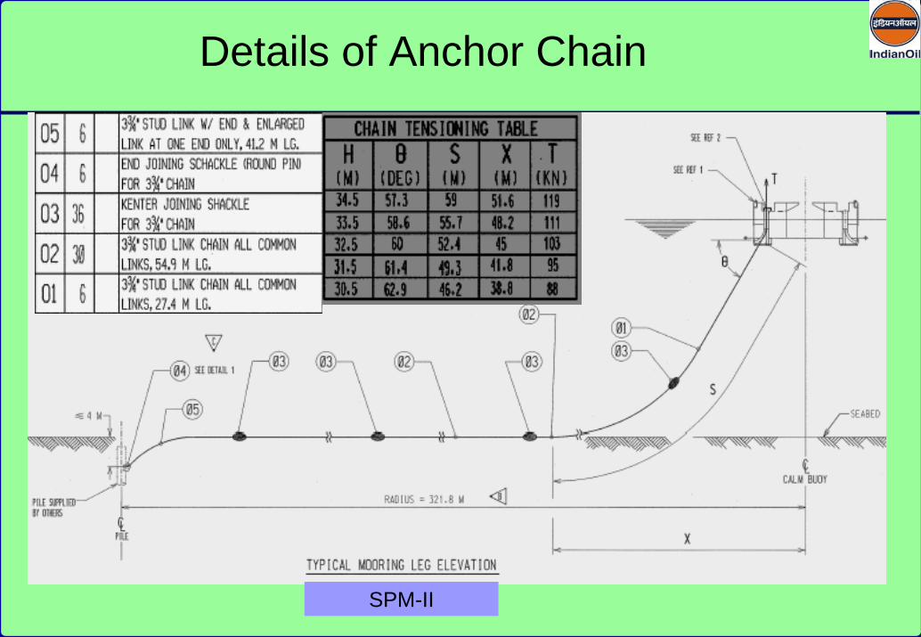
SPM-II
Details of Anchor Chain

Major componentsFloating BuoyTurntablea) Mooring Armb) Pipe Armc) Balance ArmPDU
Major Components of Buoy
Floating Hoses
Mooring Ropes
Pipe Arm
Mooring Arm
Balance Arm Navigation Light
Major Components of Buoy

Buoy Hull is circular, all welded steel structure that is sub divided into Seven (Six radial & one central) water tight compartments separated by radial bulk heads.Alternative radial compartments are filled with foam for buoyancy.Central compartments is designated as access / storage compartments and is provided with following:
PLEM Hydraulic Control UnitManual Bilge pump with suction & discharge hoseDCP fire extinguisherPortable explosion proof hand lanternMiscellaneous items required by operators
Chain Hawser pipe is integral with six radial bulk heads Six deck mounted pad eyes integral with water tight bulk heads for lifting the entire buoy.
Buoy Hull

PDU & Chain Hawser System

Turn table on Central Swivel BearingTurn table rotates on central bearing. Wear and tear due to rotation of turn table is less. However, if bearing fails, insitu replacement is not possible. Requires to be changed during dry dock only.
Turn table on Bogey WheelsTurn table is mounted on bogey wheels moving on lower deck of Buoy.Due to wear on bogey wheels, replacement of the same are required at frequent intervals. Wear on buoy body necessitates dry docking at frequent intervals.
Turn table on Wheels & Rail TrackTurn table is mounted on wheels moving on rail track which is positioned on the deck of Buoy.
Types of Turn table

RAIL TRACK TYPE BUOY

RAIL TRCAK & MAIN BERING TYPE BUOYS
RAIL TRACK & MAIN BEARING TYPE BUOYS

Typical Buoy dimensions
Main BearingPDU Bearing
Buoyancy of SPM
Buoy Draft (Installed) Buoy HeightBuoy ID Buoy Dia
(Outer)
Buoy Dia
(Inner)Mtr Displacement Mtr Displacement
Freeboard Buoyancy
1087 1087 (S)(S)
11.00 3.73 3.20 274.38 MT 4.82 413.29 MT 138.91 138.91 MTMT
1218 1218 (I)(I)
12.50 0.00 2.20 275.24 MT 4.26 532.97 MT 257.73 257.73 MTMT
1555 1555 (II)(II)
12.50 0.00 2.30 287.75 MT 4.27 534.22 MT 246.47 246.47 MTMT

395 +/- 5 M
Anchoring System of Buoy
SPM-I SPM-IIAnchor Piles
PLEM Piles
Anchor Piles
PLEM Piles
No of Piles 06 04 06 04Diameter 1000 mm 400 mm 1524 mm 508 mm
Wall Thickness of Casing
38 mm 13 mm 44 mm 19 mm
Length of Pile
9 m 7 m 15 m 12.2 m
Pile Dimensions of Buoy and PLEM
SPM-II
Details of Anchor Chain


1. 110 t shackles
2. Mooring Chain
3. Mooring Hawser
4. Antichaffing Chains
5. Support Buoy
6. Wire Pendent
7. Messenger Rope
8. Pickup Rope
9. Pick Up buoy
Components of Tanker Mooring System

Supporting buoy – net buoyancy-2170 KG
Mooring Rope- 14” Cir.
ANTI CHAFFING CHAIN
110 t shackle
Thimble
Tanker Mooring Arrangement
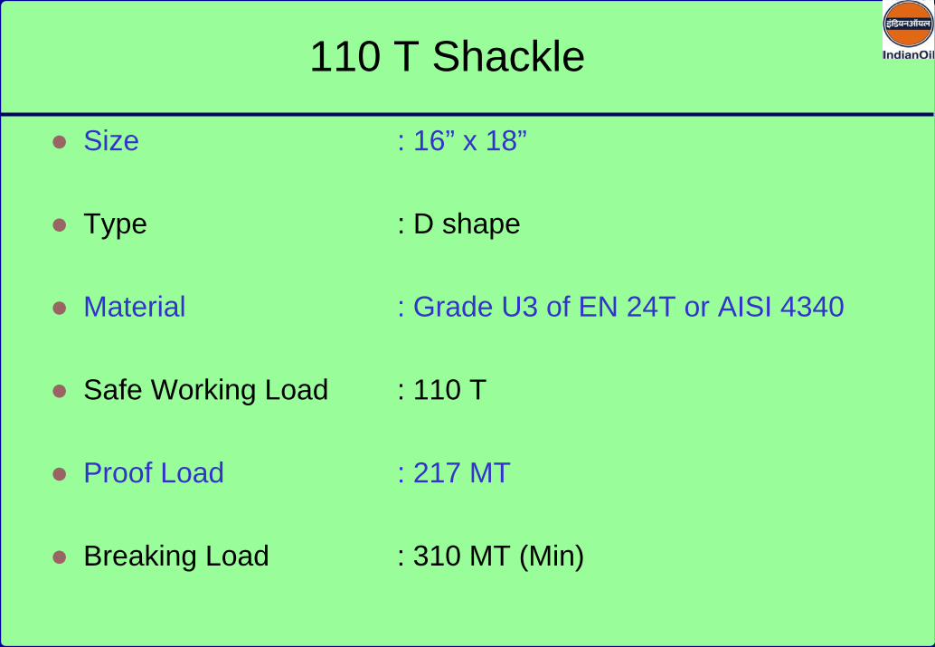
Size : 16” x 18”
Type : D shape
Material : Grade U3 of EN 24T or AISI 4340
Safe Working Load : 110 T
Proof Load : 217 MT
Breaking Load : 310 MT (Min)
110 T Shackle

Designation SO 1087
IM 1555
IM 1218
Hawser arrangement Twin lines
Twin lines
Twin lines
Material Nylon Nylon Nylon
Hawser length (m/feet) 54.8 / 180
54.8 / 180
54.8 / 180
Dyn. design mooring force (tonnes)
250 270 220
Mooring Hawser
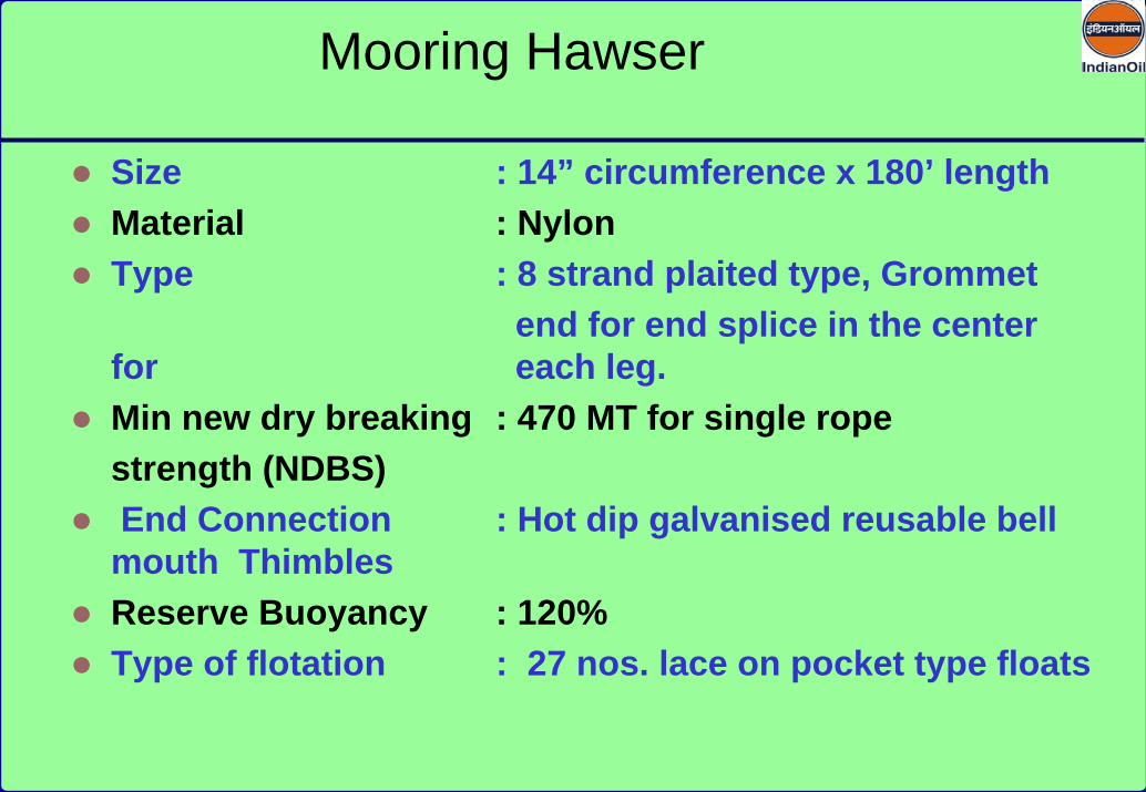
Size : 14” circumference x 180’ lengthMaterial : Nylon Type : 8 strand plaited type, Grommet
end for end splice in the center for each leg.Min new dry breaking : 470 MT for single rope strength (NDBS)End Connection : Hot dip galvanised reusable bell mouth ThimblesReserve Buoyancy : 120%Type of flotation : 27 nos. lace on pocket type floats
Mooring Hawser

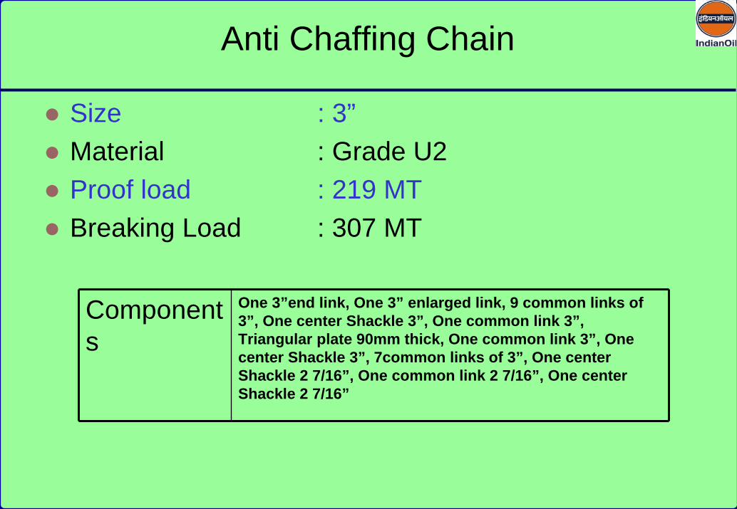
Size : 3”Material : Grade U2Proof load : 219 MTBreaking Load : 307 MT
Components
One 3”end link, One 3” enlarged link, 9 common links of 3”, One center Shackle 3”, One common link 3”, Triangular plate 90mm thick, One common link 3”, One center Shackle 3”, 7common links of 3”, One center Shackle 2 7/16”, One common link 2 7/16”, One center Shackle 2 7/16”
Anti Chaffing Chain

Over all length : 2.3 M to 2.7 MLength of Floatation : 1.7 M to 2.0 MDia. Of Floatation : 1.3 M to 1.5 MNet Buoyancy : 2.2 TCore : Polyethylene Foam (special close cell ,
low density, low water absorbent)Skin : 12 mm Polyurethane elastomerSwivel assembly : 16 T proof loadSwivel finish : Hot dip galvanised Carbon steelCentral steel work : Carbon Steel
Support Buoy
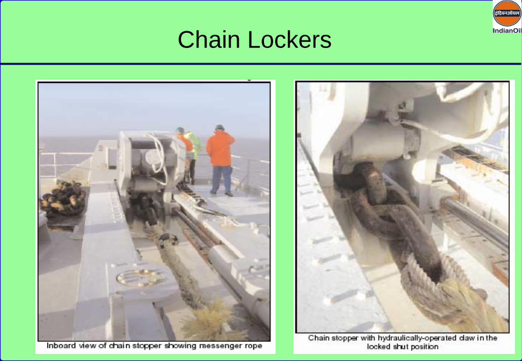
Chain Lockers


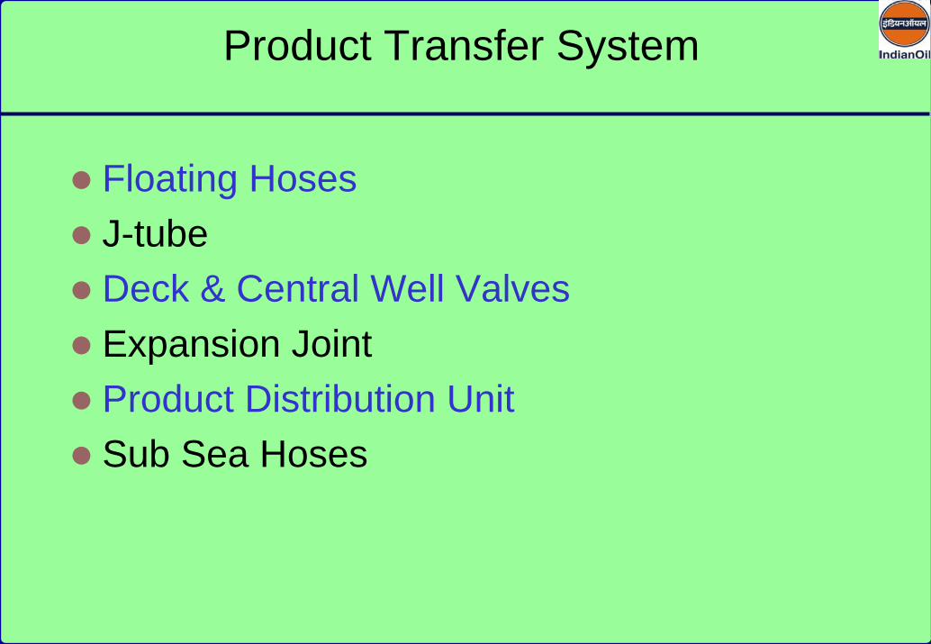
Floating HosesJ-tubeDeck & Central Well ValvesExpansion JointProduct Distribution UnitSub Sea Hoses
Product Transfer System
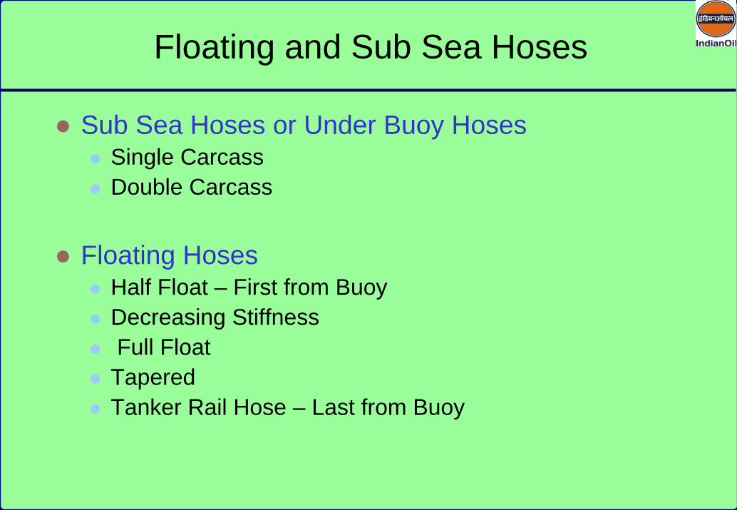
Sub Sea Hoses or Under Buoy HosesSingle CarcassDouble Carcass
Floating HosesHalf Float – First from BuoyDecreasing StiffnessFull Float TaperedTanker Rail Hose – Last from Buoy
Floating and Sub Sea Hoses

Floating Hose String
Floating hose string consists of hoses of varying degrees of stiffness to help transition stress from the start of the floating hoses to the ship’s manifold.Decreasing stiffness hoses is provided after first hose off the buoy.Tapered hoses as well as metallic reducers with built-in flotation are also used.At the end of the tanker rail hose , the thickness of the foam layer is increased to compensate for the weight of butterfly valve , spool piece, blind flange etc. The total no. of electrical discontinuous hose sections depend on the maximum free-board of the tankers using the SPM.

Hose to Buoy Connection
Responses of buoy and the hose to wave , wind and current stress are different .The environment forces create cyclic bending moments & tension ,compression and torsional loadings.Due to this problem arise in the first and second hose off the buoy.These problems can be reduced by::
Maintaining the centre of the hose/overboard pipe connection apprx. At mean sea level.
The face of the flange of vertical pipe is kept at 150 with the vertical.
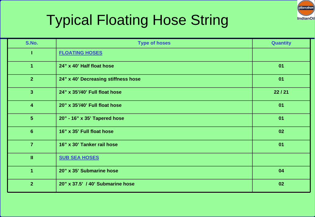
S.No. Type of hoses Quantity
I FLOATING HOSES
1 24” x 40’ Half float hose 01
2 24” x 40’ Decreasing stiffness hose 01
3 24” x 35’/40’ Full float hose 22 / 21
4 20” x 35’/40’ Full float hose 01
5 20” - 16” x 35’ Tapered hose 01
6 16” x 35’ Full float hose 02
7 16” x 30’ Tanker rail hose 01
II SUB SEA HOSES
1 20” x 35’ Submarine hose 04
2 20” x 37.5’ / 40’ Submarine hose 02
Typical Floating Hose String


1. 110 t shackles
2. Mooring Chain
3. Mooring Hawser
4. Antichaffing Chains
5. Support Buoy
6. Wire Pendent
7. Messenger Rope
8. Pickup Rope
9. Pick Up buoy
Components of Tanker Mooring System

Supporting buoy – net buoyancy-2170 KG
Mooring Rope- 14” Cir.
ANTI CHAFFING CHAIN
110 t shackle
Thimble
Tanker Mooring Arrangement

Size : 16” x 18”
Type : D shape
Material : Grade U3 of EN 24T or AISI 4340
Safe Working Load : 110 T
Proof Load : 217 MT
Breaking Load : 310 MT (Min)
110 T Shackle

Designation SO 1087
IM 1555
IM 1218
Hawser arrangement Twin lines
Twin lines
Twin lines
Material Nylon Nylon Nylon
Hawser length (m/feet) 54.8 / 180
54.8 / 180
54.8 / 180
Dyn. design mooring force (tonnes)
250 270 220
Mooring Hawser

Size : 14” circumference x 180’ lengthMaterial : Nylon Type : 8 strand plaited type, Grommet
end for end splice in the center for each leg.Min new dry breaking : 470 MT for single rope strength (NDBS)End Connection : Hot dip galvanised reusable bell mouth ThimblesReserve Buoyancy : 120%Type of flotation : 27 nos. lace on pocket type floats
Mooring Hawser
Size : 3”Material : Grade U2Proof load : 219 MTBreaking Load : 307 MT
Components
One 3”end link, One 3” enlarged link, 9 common links of 3”, One center Shackle 3”, One common link 3”, Triangular plate 90mm thick, One common link 3”, One center Shackle 3”, 7common links of 3”, One center Shackle 2 7/16”, One common link 2 7/16”, One center Shackle 2 7/16”
Anti Chaffing Chain

Over all length : 2.3 M to 2.7 MLength of Floatation : 1.7 M to 2.0 MDia. Of Floatation : 1.3 M to 1.5 MNet Buoyancy : 2.2 TCore : Polyethylene Foam (special close cell ,
low density, low water absorbent)Skin : 12 mm Polyurethane elastomerSwivel assembly : 16 T proof loadSwivel finish : Hot dip galvanised Carbon steelCentral steel work : Carbon Steel
Support Buoy

Chain Lockers

Floating HosesJ-tubeDeck & Central Well ValvesExpansion JointProduct Distribution UnitSub Sea Hoses
Product Transfer System

Sub Sea Hoses or Under Buoy HosesSingle CarcassDouble Carcass
Floating HosesHalf Float – First from BuoyDecreasing StiffnessFull Float TaperedTanker Rail Hose – Last from Buoy
Floating and Sub Sea Hoses

Floating Hose String
Floating hose string consists of hoses of varying degrees of stiffness to help transition stress from the start of the floating hoses to the ship’s manifold.Decreasing stiffness hoses is provided after first hose off the buoy.Tapered hoses as well as metallic reducers with built-in flotation are also used.At the end of the tanker rail hose , the thickness of the foam layer is increased to compensate for the weight of butterfly valve , spool piece, blind flange etc. The total no. of electrical discontinuous hose sections depend on the maximum free-board of the tankers using the SPM.

Hose to Buoy Connection
Responses of buoy and the hose to wave , wind and current stress are different .The environment forces create cyclic bending moments & tension ,compression and torsional loadings.Due to this problem arise in the first and second hose off the buoy.These problems can be reduced by::
Maintaining the centre of the hose/overboard pipe connection apprx. At mean sea level.
The face of the flange of vertical pipe is kept at 150 with the vertical.

S.No. Type of hoses Quantity
I FLOATING HOSES
1 24” x 40’ Half float hose 01
2 24” x 40’ Decreasing stiffness hose 01
3 24” x 35’/40’ Full float hose 22 / 21
4 20” x 35’/40’ Full float hose 01
5 20” - 16” x 35’ Tapered hose 01
6 16” x 35’ Full float hose 02
7 16” x 30’ Tanker rail hose 01
II SUB SEA HOSES
1 20” x 35’ Submarine hose 04
2 20” x 37.5’ / 40’ Submarine hose 02
Typical Floating Hose String

1 2 233-22Hose No.
Hose Desc.
30 48 6072Hose Life
24” x 40’Hose Size 24” x 40’ 24” x 40’24”-20” x
4.67’ 20” x 40’
Full Float Full Float Hose Tanker RailDecreasing Stiffness
Floating Hoses
Half Float Hose
Full Float Hose
MBC Tapered Hose
25 26
45 30
16” x 35’ 16” x 35’
27
16” x 30’
45
24
60
20”-16” x 35’
Condition based
3.75’
Condition based
Floating Hose String (An example)
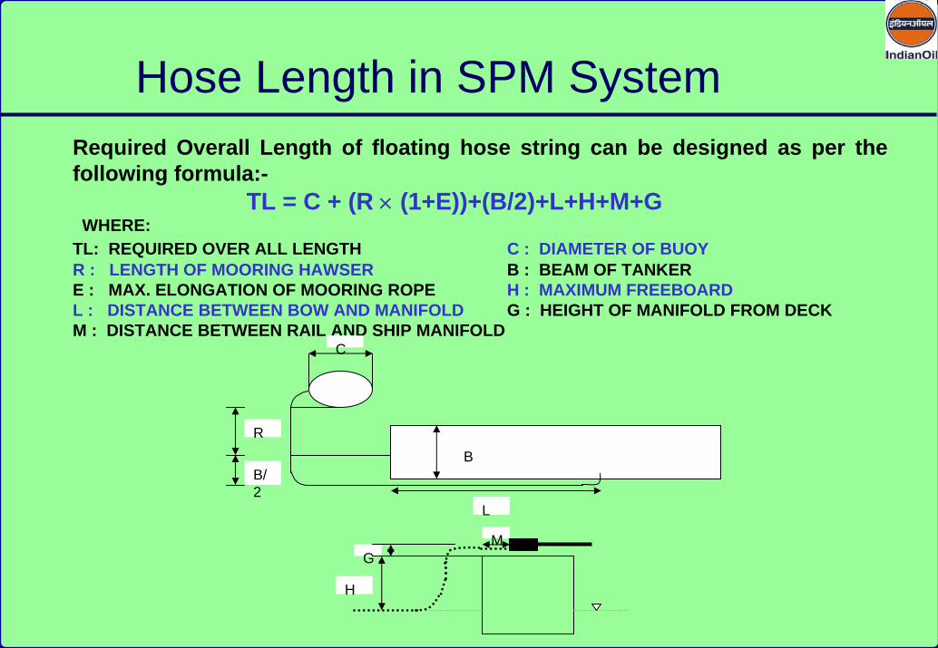
Hose Length in SPM SystemRequired Overall Length of floating hose string can be designed as per the following formula:-
TL = C + (R × (1+E))+(B/2)+L+H+M+GWHERE:
TL: REQUIRED OVER ALL LENGTH C : DIAMETER OF BUOYR : LENGTH OF MOORING HAWSER B : BEAM OF TANKERE : MAX. ELONGATION OF MOORING ROPE H : MAXIMUM FREEBOARDL : DISTANCE BETWEEN BOW AND MANIFOLD G : HEIGHT OF MANIFOLD FROM DECKM : DISTANCE BETWEEN RAIL AND SHIP MANIFOLD
G
H
M
B
C
L
R
B/2
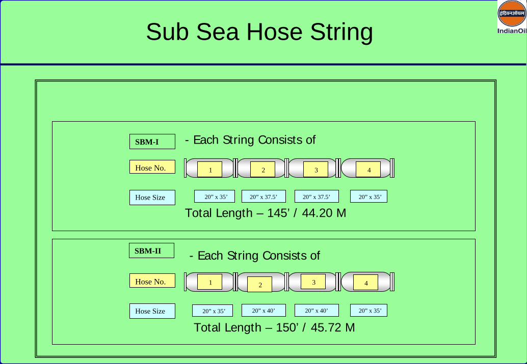
SBM-I
Hose No.
20” x 35’Hose Size 20” x 37.5’ 20” x 37.5’ 20” x 35’
SBM-II
Hose No.
20” x 35’Hose Size 20” x 40’ 20” x 40’ 20” x 35’
1 2 3 4
- Each String Consists of
1 2 3 4
- Each String Consists of
Total Length – 145’ / 44.20 M
Total Length – 150’ / 45.72 M
Sub Sea Hose String

45.7
20 M
32.5
00 M
BUOY
WATERDEPTH
END FLOAT BODY FLOAT
Configuration of Sub Sea Hose String

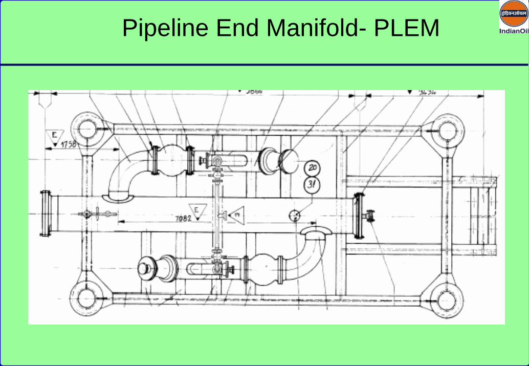
Pipeline End Manifold- PLEM

24” BALL VALVE (HYD OPERATED
Pipeline End Manifold- PLEM
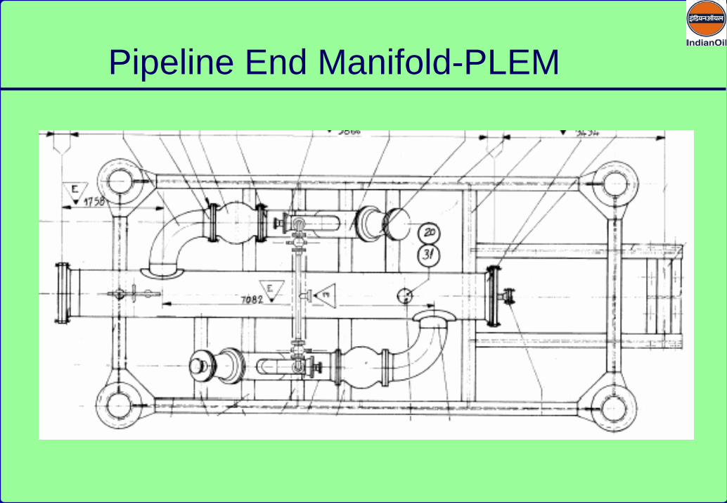
Pipeline End Manifold-PLEM
Pipeline End Manifold-PLEM
24” BALL VALVE (HYD OPERATED)

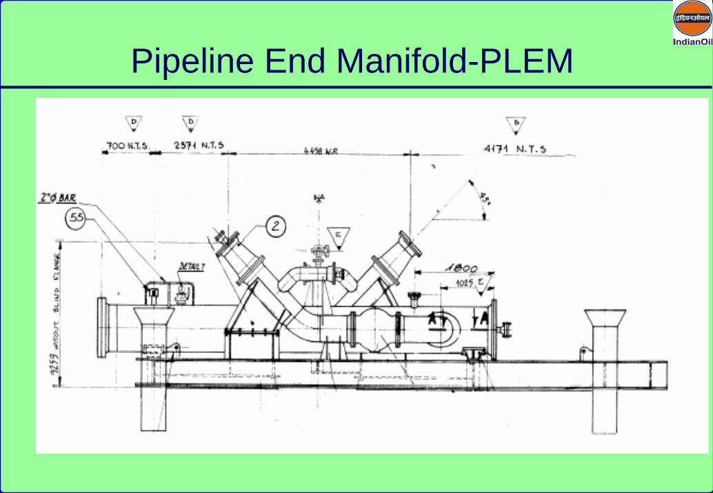
PLEM VIEW

PLEM VIEW

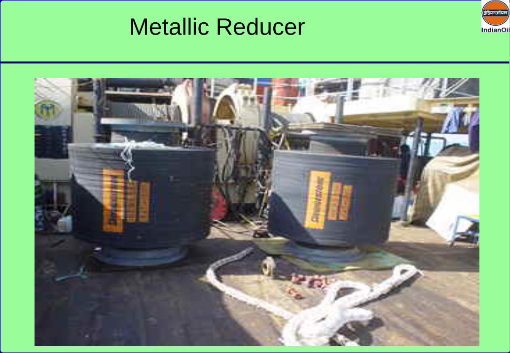
Metallic Reducer

Size : 20” NB (19.25” ID) ( Max. Dia : 28.75”, Length : 11.75”Make : M/s Gail Thompson Environmental plc, UKDouble energized anti pollution petal vane closerDesign Parting Load: 45 TDesign Pressure : 225 psiDesign Temperature: - 100 C to 850 CDesign Closure Speed :
Upstream : InstantaneousDownstream : Adjustable to prevent damage to system
Marine Breakaway Coupling
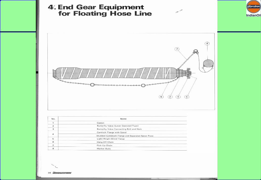

End Gear Arrangement of Floating Hose
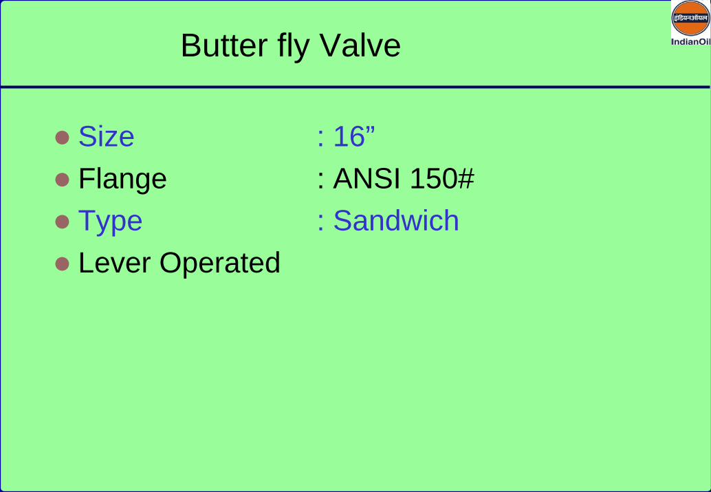
Size : 16”Flange : ANSI 150#Type : SandwichLever Operated
Butter fly Valve

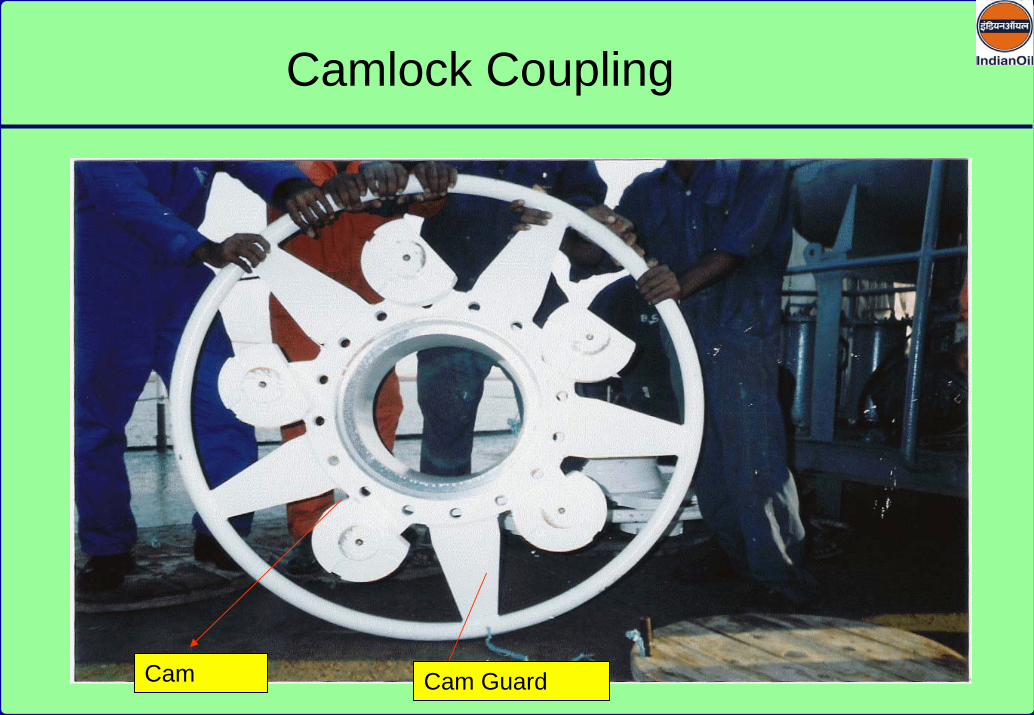
Cam GuardCam
Camlock Coupling

Camlock Coupling
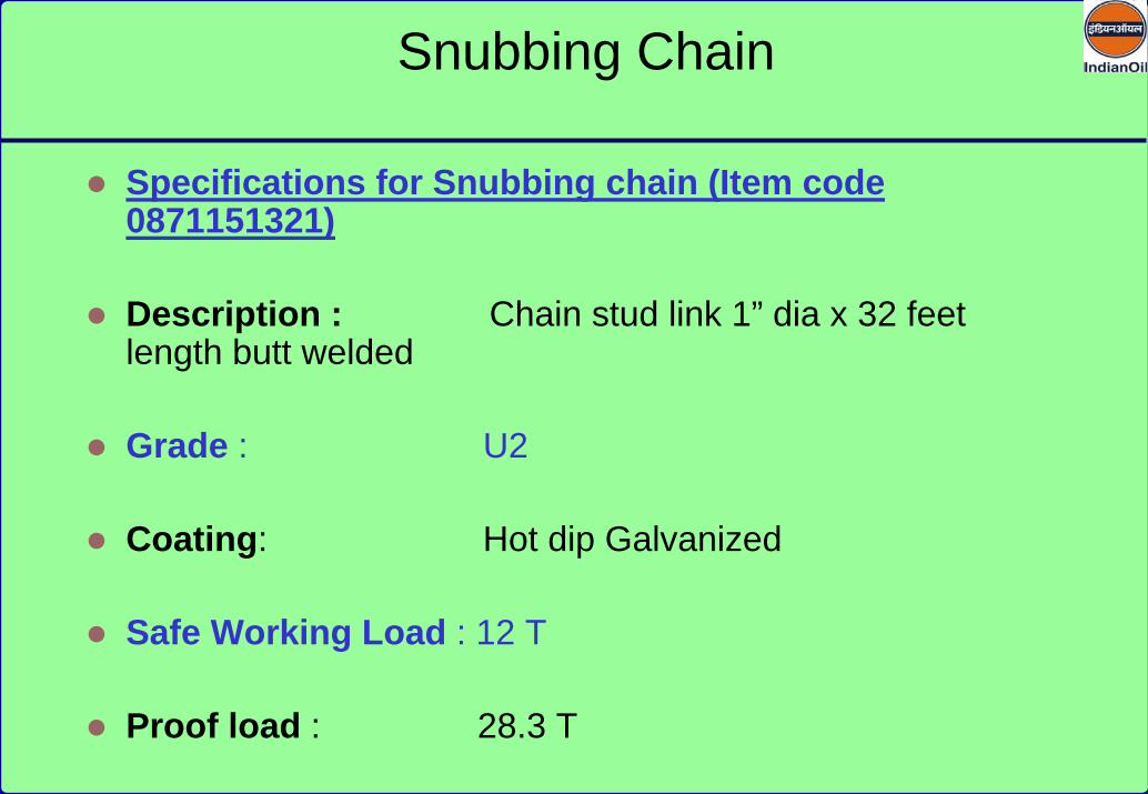
Specifications for Snubbing chain (Item code 0871151321)
Description : Chain stud link 1” dia x 32 feet length butt welded
Grade : U2
Coating: Hot dip Galvanized
Safe Working Load : 12 T
Proof load : 28.3 T
Snubbing Chain

Manifold Connection