single band: f10f-g/d/w/lte1800 dual band: f10f … · single band: f10f-g/d/w/lte1800 dual band:...
TRANSCRIPT

1
Single Band: F10F-G/D/W/LTE1800
Dual Band: F10F-GD/GW
Triple Band: F10F-GDW

2
Table of content
Preface ..................................................................................... 3
Safety Warnings ...................................................................... 3
Overview .................................................................................. 4
Package contents ................................................................... 4
Install your hardware .............................................................. 6
Troubleshooting .................................................................... 14
Specifications ........................................................................ 15
Product Warranty .................................................................. 16

3
Preface
This user's manual describes the installation, commissioning and
maintenance of F10F series wide band consumer boosters of
single band, dual band and triple band.
Please do read user manual carefully before installing and
maintaining the booster.
The information in this manual is subject to change without prior
notice.
Opinions are welcomed about the manual improvement.
Safety Warnings
Users must follow the below principles:
Booster should follow system requirement of communication
equipment, assure good grounding and lightning protection.
The power supply voltage of booster should meet the standards of
security requirement; any operation shall be carried out only after cutting
off power in advance. Only the professional is authorized for the operation.
Do not dismantle machine, maintain or displace accessories by
yourself, because in this way, the equipment may be damaged and you
may even get an electric shock.
Do not open the booster, touch the module of booster, or open the
cover of module to touch the electronic component. The components will
be damaged due to electrostatic.
Please keep away from heating-equipment, because the booster
will dissipate heat during working. And do not cover booster with anything
that influences heat-dissipation.
4
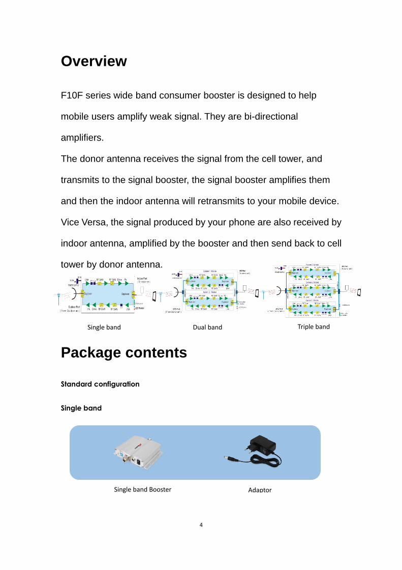
Overview
F10F series wide band consumer booster is designed to help
mobile users amplify weak signal. They are bi-directional
amplifiers.
The donor antenna receives the signal from the cell tower, and
transmits to the signal booster, the signal booster amplifies them
and then the indoor antenna will retransmits to your mobile device.
Vice Versa, the signal produced by your phone are also received by
indoor antenna, amplified by the booster and then send back to cell
tower by donor antenna.
Package contents
Standard configuration
Single band
Single band Booster Adaptor
Single band Dual band Triple band

5
Dual band
Triple band
Optional accessories
Outdoor panel antenna Whip antenna Coaxial cable
Dual band Booster Adaptor
Triple band Booster Adaptor

6
Install your hardware
Before you install
Make sure you have sufficient cable length between
proposed donor/server antenna location and booster
connector.
Make sure the position you install the booster is near to one
existing electrical outlet, and well ventilated, away from
excessive heat, moisture, and direct sunlight.
Install tools and accessories:
Num. Name Specification Quantity Remark
1 Plastic expansion bolt Ø6 5 Standard accessories
2 Tapping screw M4*25 4 Standard accessories
3 Hanging folder 1 Standard accessories
4 Reciprocating drill 1 Engineering-owned
5 Shot bit Ø6 1 Engineering-owned
Installation overview
Install your outdoor antenna on the roof where there is the
strongest signal.
Mount your signal booster, Connect the cables to the signal
booster from the Outdoor antenna and Indoor antenna at
the designated ports, and connect the booster to the AC
supply (make sure all the cables are connected).
Install the indoor antenna where you want to improve the
signal.

7
Find the area with the strongest signal
The booster’s main function is to improve weak RF signal of an
area. The signal strength from the outdoor antenna directly affects
the efficiency of the indoor coverage.
Install the Outdoor Antenna
Select a proper place to install the outdoor antenna.
Normally the proof of the building is a good choice. As shown
from the above graph, you need to test the signal from A to E,
and select a place with best signal for installation.
Select the directions for outdoor antenna
The donor antenna should point to the tower for better signal.
Installation of outdoor antenna
In most cases, Logarithmic periodic antenna is the best choice.
You can also choose outdoor panel antenna or YAGI antenna
as other options.
There are 2 types of installation: wall mount or pole mount.
Wall mounts are recommended for your convenience.
Install outdoor panel antenna as reference:
Step1: Unscrew antenna from L-mounting bracket on antenna
base with wrench.

8
Step2: Mount vertical plate of the L-bracket on the wall with
supplied screws.
Step3: Screw antenna back onto horizontal plane.
Notes:
Wrap waterproof tape around the connectors between donor antenna and feeder lines to avoid
water or other kinds of damage
Install the Indoor Antenna
According to the requirement of practical application, to choose
Indoor panel antenna, Omni-directional antenna or whip antenna
as server antenna.
Install indoor panel and whip antenna as reference:
Step1: Select a place on a wall projecting the area where you
want reception.
Normally, to provide an overall coverage, you will need to

9
choose a corner.
Step2: Mount bracket on the wall after drilling the screw to the
wall.
Step3: Put the panel antenna on the bracket.
Install the signal booster
Step1: Select a location close to a power outlet on a wall.
Step2: Mount the booster with screws included as shown in
the figure.
Step3: Connect the outdoor antenna cables to booster
connector marked “outdoor”. Tighten the connection with
hand or wrench.
Step4: Connect the indoor antenna cables to booster
connector marked “indoor”. Tighten the connection with hand
or wrench.
Step5: Connect the AC power cord to the signal booster, then
connected the plug to the electrical outlet.
Step6: Power on the booster.
Indoor panel antenna Whip antenna

10
Booster‘s ports description
Single band
1. LED 2. Dip Switch 3. Outdoor Port 4. DC IN
5. Power Switch 6. Indoor Port
Booster installation Connection from cable to Booster

11
Dual band
1. LED 2. Dip Switch 3. Indoor Port 4. DC IN 5. Outdoor Port
Triple band
1. Indoor Port 2. LED 3. Dip Switch 4. Outdoor Port
5. DC IN 6. Power Switch
Booster Commissioning
After powering on the booster, it will automatically adjust for best
performance with the intelligent automatic gain control function. No
manual operation is needed.
If the alarm LED flashes green or orange, that means
the booster is working properly. In this case, you can

12
check the coverage, if it is good, the commissioning is
finished. If not, you can adjust outdoor antenna location
to get a better signal strength and move the indoor
antenna to face the weak signal area directly.
If the alarm LED is flashing red, that means self-
oscillation is occuring, you can adjust the antenna to
enhance the isolation which normally can be fulfilled by
adding the distance or barrier between the outdoor
antenna and indoor antenna. Adjust until the alarm LED
turns green or orange.
If the alarm is still flashing red, the MGC function can provide
further assistance as show below.
DIP switch
The DIP switches used for manually adjust their
respective band gain attenuations.
Switches1-2 control G/D/W/LTE1800/GD/GW band’s DL atten
uation, 3-4 control G/D/W/LTE1800/GD/GW band’s UL attenu
ation.
The DIP switches used for manually adjust their
respective band gain attenuations.
Switches1-4 control G/D/W band’s DL attenuation,
5-8control G/D/W band’s UL attenuation.
13
The booster will work on its MAX. gain mode, in some cases, we don’t need
such big value. MGC function will help to provide a loss. For example, in the
above image, 1 represent 1dB and 2 represent 2dB, if you press both 1 and 2
button, you can get a loss of 1dB plus 2 dB which is 3 dB loss.
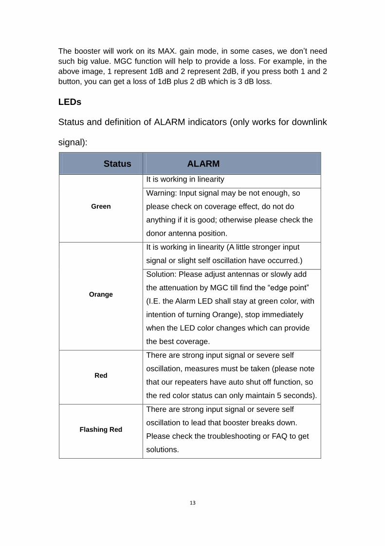
LEDs
Status and definition of ALARM indicators (only works for downlink
signal):
Status ALARM
Green
It is working in linearity
Warning: Input signal may be not enough, so
please check on coverage effect, do not do
anything if it is good; otherwise please check the
donor antenna position.
Orange
It is working in linearity (A little stronger input
signal or slight self oscillation have occurred.)
Solution: Please adjust antennas or slowly add
the attenuation by MGC till find the “edge point”
(I.E. the Alarm LED shall stay at green color, with
intention of turning Orange), stop immediately
when the LED color changes which can provide
the best coverage.
Red
There are strong input signal or severe self
oscillation, measures must be taken (please note
that our repeaters have auto shut off function, so
the red color status can only maintain 5 seconds).
Flashing Red
There are strong input signal or severe self
oscillation to lead that booster breaks down.
Please check the troubleshooting or FAQ to get
solutions.

14
Off
Booster breaks down, or severe self oscillation
leads to auto mute. Please re-plug in and check if
alarm LED turns red, if it is, please take measures
to keep alarm LED green; if it maintains off, it
means the power break down.
Troubleshooting
problem Resolution
The signal booster is no
power.
Check the booster switch is turned on.
Check the AC outlet is working.
The booster’s power is on
but the phone is not
connected into the
network and still can not
communicate.
Try to fasten the connections between the different
parts of the system.
Change the direction of donor antenna or its installation
position
Use barriers (like buildings) to block signals of other
operators.
Good downlink signal with
poor communication
quality
Check whether there’s interference
Consult the operator whether the signal source base
station works well
Adjust uplink gain to balance uplink and downlink
The power is on but it has
a signal fluctuation or a
flash signal.
Firstly check whether the alarm LED is orange. The
orange light shows the insufficient isolation.
Secondly adjust the antennas’ directions or locations or
enlarge the distance between them.
Thirdly reduce the booster’s gain by ATT DIP if the
above methods don’t work.

15
Specifications
RF Parameter Uplink Downlink
Frequency Range GSM900&UMTS 890~915MHz 935~960 MHz
DCS*LTE 1710~1785MHz 1805~1880MHz
WCDMA 1920~1980MHz 2110~2170MHz
Max .Gain
F10F-G/D/W/LTE1800 55dB 60dB
F10F-GD/GW 55dB 60dB
F10F-GDW 55dB 60dB
Max .Output
Power
F10F-G/D/W/LTE1800 10dBm 10dBm
F10F-GD/GW 10dBm 10dBm
F10F-GDW 10dBm 10dBm
MGC ( Step
Attenuation )
F10F-G/D/W/GD/GW ≥ 15dB / 5dB step, dip switch control
F10F-GDW ≥ 31dB /15dB step, dip switch control
AGC Adjust automatic
V.S.W.R Typical≤ 2
Electrical Parameter
Impedance 50 ohm
Power Supply
F10F-G/D/W Input AC90~264V,output DC7.5V/0.8A
F10F/GD/GW Input AC90~264V,output DC7.5V/1.5A
F10F-GDW Input AC90~264V,output DC12V/3A
LED Alarm Power LED Power Indicator
ALC LED Orange @ ALC 1~5 dB, Red @ ALC 20
dB ~25 dB
Mechanical Parameter Mechanical Parameter
I /O Port N-Female
Dimensions
F10F-G/D/W 5.1*3.7*1.2inch/129*95*30mm
F10F/GD/GW 5.1*6.1*1.2inch/129*156*30mm
F10F-GDW 9.9*8.7*2.1inch/250*220*53mm
Weights
F10F-G/D/W ≤1.4Lbs/0.65KG
F10F/GD/GW ≤1.9lbs/0.85KG
F10F-GDW ≤6.6lbs/3KG
Environment Parameter Operating Temperature -25ºC~+55ºC
Relative humidity 5% - 95%
Barometric pressure 55 kPa -106 kPa
Environment Conditions IP40

16
Product Warranty
30-Day Money-Back Guarantee
All Hiboost products are protected by a 30-day money-back
guarantee. If for any reason the performance of any product is not
acceptable, the product may be replaced or returned to the reseller
with a dated proof of purchase.
2-Year Warranty
Hiboost Signal Boosters are warranted for 2 years. Customers can
choose to replace or return the Signal Boosters and kits directly to
the manufacturer at the purchase expense excluding 20%, with a
dated proof of purchase and a Returned Material Authorization
(RMA) number supplied by Hiboost.
This warranty does not apply to any Signal Boosters or kits
determined by Hiboost to have been subjected to misuse, abuse,
neglect, or mishandling that alters or damages physical or
electronic properties. Failure to use a surge protected AC Power
Strip with at least a 1000 Joule rating will void your warranty.
All Hiboost products that are packaged with other Hiboost
accessory products are intended for resale and use as a single unit,
and such product kits are required to be sold to the end users or
subsequent reseller as packaged.
For any questions or suggestions contact our Technical Support by
email [email protected].

17