single ampli er biquad based inductor-free chua’s circuit · nonlinear dynamics manuscript no....
TRANSCRIPT

Nonlinear Dynamics manuscript No.(will be inserted by the editor)
Single amplifier biquad based inductor-free Chua’s circuit
Tanmoy Banerjee
Received: date / Accepted: date
Abstract The present paper reports an inductor-free
realization of Chua’s circuit, which is designed by suit-
ably cascading a single amplifier biquad based active
band pass filter with a Chua’s diode. The system has
been mathematically modeled with three-coupled first-
order autonomous nonlinear differential equations. It
has been shown through numerical simulations of the
mathematical model and hardware experiments, that
the circuit emulates the behaviors of a classical Chua’s
circuit, e.g., fixed point behavior, limit cycle oscilla-
tion, period doubling cascade, chaotic spiral attractors,
chaotic double scrolls and boundary crisis. The occur-
rence of chaotic oscillation has been established through
experimental power spectrum, and quantified with the
dynamical measure like Lyapunov exponents.
Keywords Active Bandpass Filter · Chaotic electronic
circuits · Chua’s circuit · Chaos · Bifurcation
1 Introduction
Design of chaotic electronic circuits offers a great chal-
lenge to the research community for the last three decades
[1]-[2]. The motivation for designing a chaotic electronic
circuit comes mainly from two facts: first, one can ‘ob-
serve’ chaos, and can also control the dynamics of the
circuit by simply changing the physically accessible pa-
rameters of the circuit, e.g., resistor, capacitor, volt-
age levels, etc.; second, there are multitude of appli-
cations of chaotic electronic oscillators starting from
T. BanerjeeNonlinear Electronics Research Laboratory (RF and Mi-crowave), Department of Physics, The University of Burd-wan, Burdwan 713 104, West Bengal, India.E-mail: [email protected]
chaotic electronic communication to cryptography [3]-
[4]. A Chua’s circuit is the first autonomous electronic
circuit where a chaotic waveform was observed experi-
mentally, established numerically, and proven theoreti-
cally [5]-[6]. Moreover, it established that chaos is not
a mathematical abstraction or numerical artifact, but
is a very much realizable phenomenon.
After the advent of chaotic Chua’s circuit, a large
number of works have been reported on different meth-
ods of realization of this circuit. All of these realizations
are mainly centered around following goals: inductor-
free realization of Chua’s circuit, and realization of Chua’s
diode. The reason behind the inductor-free realization
lies in the fact that the presence of an inductor makes
the circuit bulky, unsuitable for IC design, less robust,
etc. In the inductor-free realization, the inductor inChua’s circuit is replaced by a general impedance con-
verter (GIC) that requires at least two op-amps. An-
other approach to this end is Wien-bridge based Chua’s
circuit variant [7], where a Wien-bridge oscillator is cas-
caded properly with the Chua’s diode. In this context,
Ref. [9] and [10] report a general algorithm for design-
ing Chua’s circuit, in which it has been shown that a
sinusoidal oscillator can be converted into Chua’s cir-
cuit by incorporating a proper type of nonlinearity. Dif-
ferent realizations of Chua’s diode, which is the only
locally active nonlinearity in the circuit, have been re-
ported, e.g., Chua’s diode using VOA [11], [8], CFOA
[12], IC realization of Chua’s diode [13], etc. Also, four
element Chua’s circuit has been reported in Ref.[14],
which is the minimum component Chua’s circuit till
date. A detailed overview on the Chua’s circuit imple-
mentation can be found in Ref. [15] and [16]. Recently,
an inductor-free realization of the Chua’s circuit based
on electronic analogy has been reported [8], [17], which
provided the advantage of exploring the system dynam-
arX
iv:1
210.
8409
v1 [
nlin
.CD
] 2
9 O
ct 2
012

2 Tanmoy Banerjee
ics in the negative parameter space (i.e., negative values
of α and β of a classical Chua’s circuit [5]).
Present paper reports an inductor-free realization
of Chua’s circuit, in which we have properly cascaded
a single amplifier biquad based active band pass fil-
ter with a Chua’s diode. The system has been math-
ematically modeled with three-coupled first-order au-
tonomous nonlinear differential equations. It has been
shown through numerical solutions of the mathemati-
cal model and real world hardware experiments that the
circuit shows all the behaviors of a classical Chua’s cir-
cuit, e.g., fixed point, limit cycle formation, period dou-
bling cascade, chaotic spiral attractors, double scrolls,
and boundary crisis. Occurrence of chaos has been es-
tablished through Lyapunov exponents and experimen-
tal power spectrum.
The paper is organized in the following manner:
next section describes the proposed circuit and its math-
ematical modeling. Numerical simulations, computations
of nonlinear dynamical measures, e.g., Lyapunov ex-
ponents are reported in section 3. Section 4 gives an
account of the experimental results. Finally, section 5
concludes the outcome of the whole study.
2 Proposed circuit and its mathematical
modeling
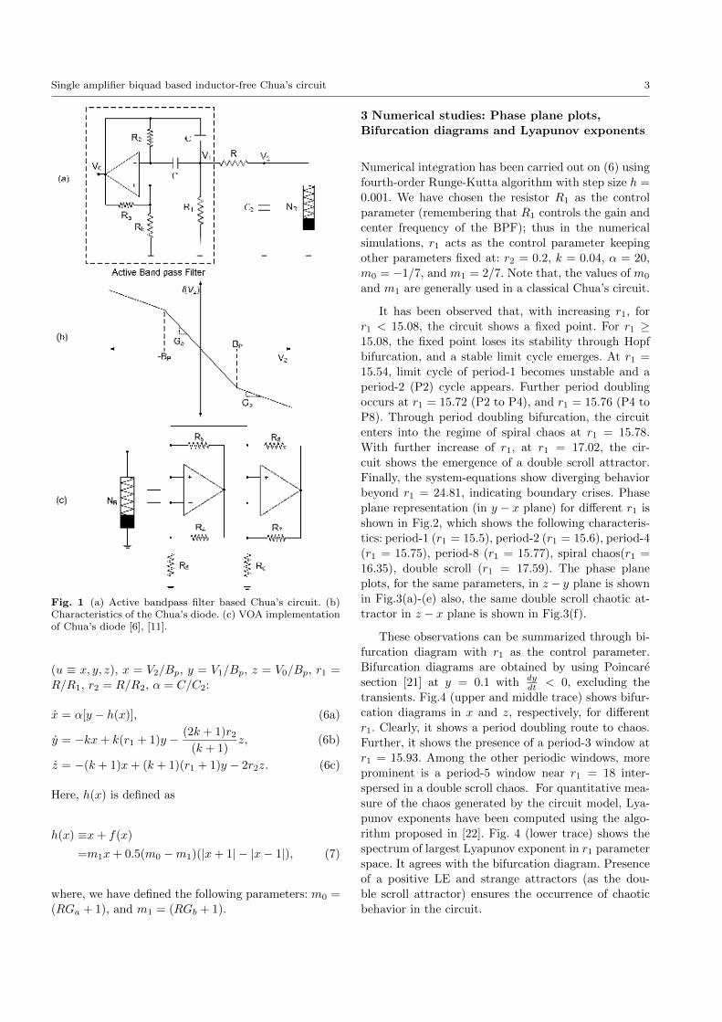
The proposed circuit is shown in Fig.1(a). This circuit
has two distinct parts: (i) a second order narrow band
active bandpass filter (BPF), and (ii) parallel combi-
nation of a grounded capacitor (C2) and Chua’s diode
(NR). V1 node of the BPF is connected to the paral-
lel combination of capacitor C2 and Chua’s diode (NR)
through a passive resistor R. Note that, the inductor-
capacitor parallel combination of a classical Chua’s cir-
cuit has been replaced by a resonator circuit, which is,
in the present circuit, an active BPF; resonant (or cen-
ter) frequency of the BPF can be controlled by simply
varying the resistors R1 or/and R2 (instead of varying
a capacitor, or an inductor).
To keep the number of active component lesser we
have chosen the single amplifier biquad based narrow
band active BPF proposed by Deliyannis and Friend
[18], [19], which consists of only one single amplifier (in
the form of an op-amp), two capacitors having same
values (C), and four resistors (R1, R2, Ra, andRb). This
active BPF is a second order system with the following
transfer function:
H(s) =−(k + 1)s/R1C
s2 + (2/R2C − k/R1C)s+ (1/R1R2C2). (1)
Here, k = Rb/Ra. Proper choice of Ra and Rb (and
hence k) makes the coefficient of s in the denominator
negative, which in turn brings the pole of the circuit
to the right half of the s-plane, resulting a sinusoidal
oscillation. Real time dynamics of the system can be
expressed in terms of the following two coupled first-
order autonomous differential equations [20]:
CdV1dt
=k
R1V1 −
(2k + 1)
(k + 1)R2V0, (2a)
CdV0dt
=(k + 1)
R1V1 −
2
R2V0. (2b)
Equation (2) can be written as:
(dV1
dtdV0
dt
)=
(k/CR1 −(2k + 1)/(k + 1)CR2
(k + 1)/CR1 −2/CR2
)×(V1V0
)=
(α11 α12
α21 α22
)(V1V0
)(3)
It can be seen from (3) that the BPF can be made
to oscillate sinusoidally if one can ensure the follow-
ing condition: α11 + α22 = 0. This in turn gives the
condition of oscillation of the sinusoidal oscillator as:
k = 2R1/R2; subsequently, the frequency of oscillation
of the sinusoidal oscillator can be obtained from the
condition:√α11α22 − α12α21 = 0. Thus the frequency
of oscillation is obtained as: ω0 = 1/C√R1R2.
Chua’s diode is characterized by the function f(V2),
where V2 is the voltage drop across C2. f(V2) is a three
segment piece wise linear function with Ga and Gb as
the slopes, and Bp is the break point voltage for those
segments. Variation of f(V2) with V2 has been shown in
Fig.1(b) (showing only the three segment region). f(V2)
is defined by:
f(V2) = GbV2 +1
2(Ga−Gb)(|V2 +Bp| − |V2−Bp|). (4)
In the present work, we have chosen the VOA imple-
mentation of Chua’s diode [6] as shown in Fig.1(c).
The dynamics of the proposed circuit can be de-
scribed by three-coupled first-order autonomous non-
linear differential equations in terms of V2, V1 and V0(Fig. 1):
C2dV2dt
=V1 − V2R
− f(V2), (5a)
CdV1dt
= − kRV2 +
k
R′ V1 −(2k + 1)
(k + 1)R2V0, (5b)
CdV0dt
= − (k + 1)
RV2 +
(k + 1)
R′ V1 −2
R2V0. (5c)
Where, R′
= R1R/(R1 +R).
Eq.(5) has been written in the following dimensionless
form using dimensionless quantities: τ = t/RC, u = dudτ
Single amplifier biquad based inductor-free Chua’s circuit 3
Fig. 1 (a) Active bandpass filter based Chua’s circuit. (b)Characteristics of the Chua’s diode. (c) VOA implementationof Chua’s diode [6], [11].
(u ≡ x, y, z), x = V2/Bp, y = V1/Bp, z = V0/Bp, r1 =
R/R1, r2 = R/R2, α = C/C2:
x = α[y − h(x)], (6a)
y = −kx+ k(r1 + 1)y − (2k + 1)r2(k + 1)
z, (6b)
z = −(k + 1)x+ (k + 1)(r1 + 1)y − 2r2z. (6c)
Here, h(x) is defined as
h(x) ≡x+ f(x)
=m1x+ 0.5(m0 −m1)(|x+ 1| − |x− 1|), (7)
where, we have defined the following parameters: m0 =
(RGa + 1), and m1 = (RGb + 1).
3 Numerical studies: Phase plane plots,
Bifurcation diagrams and Lyapunov exponents
Numerical integration has been carried out on (6) using
fourth-order Runge-Kutta algorithm with step size h =
0.001. We have chosen the resistor R1 as the control
parameter (remembering that R1 controls the gain and
center frequency of the BPF); thus in the numerical
simulations, r1 acts as the control parameter keeping
other parameters fixed at: r2 = 0.2, k = 0.04, α = 20,
m0 = −1/7, and m1 = 2/7. Note that, the values of m0
and m1 are generally used in a classical Chua’s circuit.
It has been observed that, with increasing r1, for
r1 < 15.08, the circuit shows a fixed point. For r1 ≥15.08, the fixed point loses its stability through Hopf
bifurcation, and a stable limit cycle emerges. At r1 =
15.54, limit cycle of period-1 becomes unstable and a
period-2 (P2) cycle appears. Further period doubling
occurs at r1 = 15.72 (P2 to P4), and r1 = 15.76 (P4 to
P8). Through period doubling bifurcation, the circuit
enters into the regime of spiral chaos at r1 = 15.78.
With further increase of r1, at r1 = 17.02, the cir-
cuit shows the emergence of a double scroll attractor.
Finally, the system-equations show diverging behavior
beyond r1 = 24.81, indicating boundary crises. Phase
plane representation (in y − x plane) for different r1 is
shown in Fig.2, which shows the following characteris-
tics: period-1 (r1 = 15.5), period-2 (r1 = 15.6), period-4
(r1 = 15.75), period-8 (r1 = 15.77), spiral chaos(r1 =
16.35), double scroll (r1 = 17.59). The phase plane
plots, for the same parameters, in z − y plane is shown
in Fig.3(a)-(e) also, the same double scroll chaotic at-
tractor in z − x plane is shown in Fig.3(f).
These observations can be summarized through bi-
furcation diagram with r1 as the control parameter.
Bifurcation diagrams are obtained by using Poincare
section [21] at y = 0.1 with dydt < 0, excluding the
transients. Fig.4 (upper and middle trace) shows bifur-
cation diagrams in x and z, respectively, for different
r1. Clearly, it shows a period doubling route to chaos.
Further, it shows the presence of a period-3 window at
r1 = 15.93. Among the other periodic windows, more
prominent is a period-5 window near r1 = 18 inter-
spersed in a double scroll chaos. For quantitative mea-
sure of the chaos generated by the circuit model, Lya-
punov exponents have been computed using the algo-
rithm proposed in [22]. Fig. 4 (lower trace) shows the
spectrum of largest Lyapunov exponent in r1 parameter
space. It agrees with the bifurcation diagram. Presence
of a positive LE and strange attractors (as the dou-
ble scroll attractor) ensures the occurrence of chaotic
behavior in the circuit.

4 Tanmoy Banerjee
Fig. 2 Phase plane representation (in y − x plane) for dif-ferent r1: (a)r1 = 15.5 (period-1), (b)r1 = 15.6 (period-2), (c)r1 = 15.75 (period-4), (d) r1 = 15.77 (period-8),(e)r1 = 16.35(spiral chaos), (f)r1 = 17.59 (double scroll).(r2 = 0.2, k = 0.04, α = 20, m0 = −1/7, and m1 = 2/7)
Fig. 3 Phase plane plots in z − y plane (a)-(e), and z − xplane (f) for different values of r1. Parameter values are sameas Fig.2.
4 Experimental results
The proposed circuit has been designed in hardware
level on a breadboard. Since the circuit needs three
VOAs we have chosen IC TL074 (quad JFET op-amp)
for the present purpose with ±12 volt power supply.
BPF has been constructed with C = 100 nF, Ra = 1
kΩ, Rb = 56Ω, and R2 = 10kΩ. Chua’s diode is con-
structed with following parameters [6], [11]: R3 = 2.2
kΩ, R4 = 220 Ω, R5 = 220 Ω, R6 = 3.3 kΩ, R7 = 22 kΩ,
and R8 = 22 kΩ. The grounded capacitor value is taken
Fig. 4 Bifurcation diagram of x (upper trace) and z (middletrace) with r1 as a control parameter. Lower trace shows theLargest Lyapunov exponent (λmax) with r1. (r2 = 0.2, k =0.04, α = 20, m0 = −1/7, and m1 = 2/7).
as C2 = 5 nF. Coupling resistor R is fixed at 1.3kΩ (ap-
prox.) using a 2 kΩ POT. To explore the dynamics of
the circuit we have varied the resistor R1 through a
1 kΩ POT. All the potentiometers are precision POT
having thousand turns. Capacitors and resistors have
5% tolerances.
For R1 > 200Ω the circuit shows a fixed dc value
(equilibrium point of the circuit). For R1 ≤ 200Ω a
stable limit cycle has been observed with frequency
1955Hz. At R1 = 185Ω (approx.) the limit cycle of
Single amplifier biquad based inductor-free Chua’s circuit 5
period-1 loses its stability and a period-2 oscillation
emerges. A period-4 behavior has been observed atR1 =
177Ω (approx.). period-8 is found for R1 = 175Ω (ap-
prox.). Further decrease in R1 results in spiral chaos in
the circuit (at R1 = 170Ω(approx.)). The double scroll
attractor is observed at R1 = 122Ω (approx.). The cir-
cuit shows a large limit cycle for R1 ≤ 68Ω that indi-
cates the occurrence of boundary crises, where the ac-
tive resistor becomes eventually passive , i.e., for a large
voltage across its terminals, the i − v characteristic of
Chua’s diode is no longer a three-segment curve but, it
becomes a five-segment curve. Two additional segments
(situated in two outer regions) give positive resistance
behavior, i.e., now the instantaneous power consump-
tion becomes positive [6]. All the above mentioned be-
haviors (except the large limit cycle) have been shown
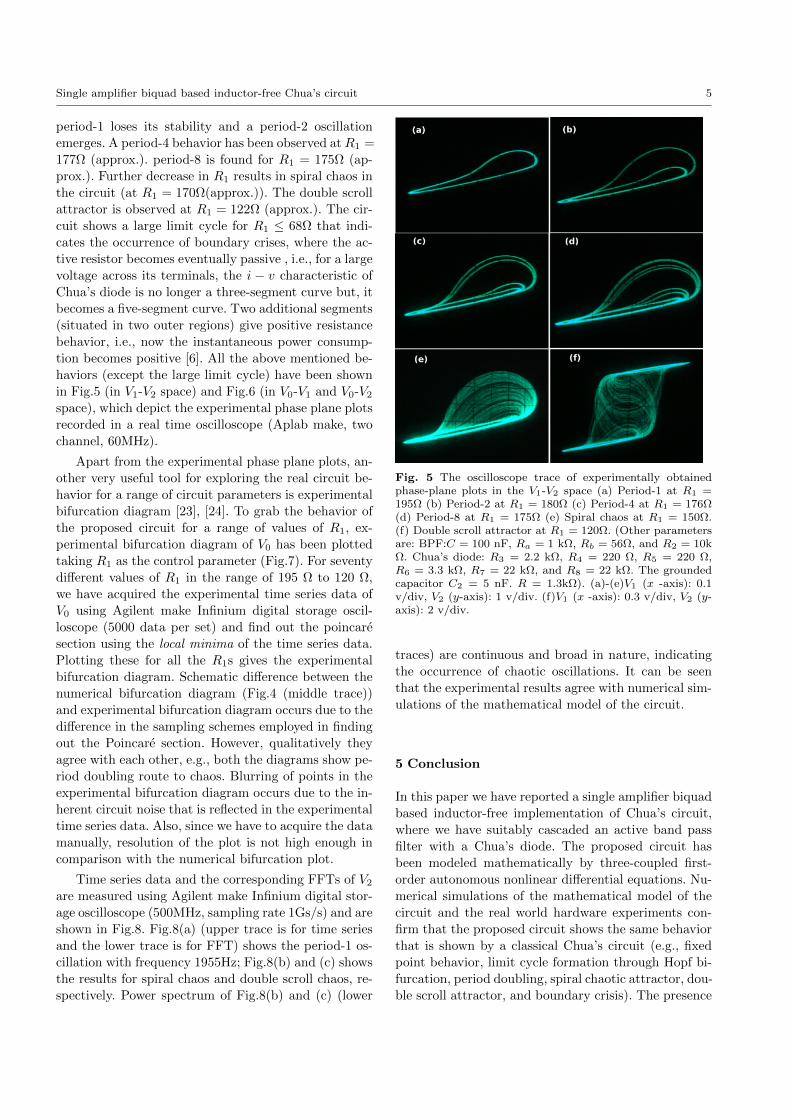
in Fig.5 (in V1-V2 space) and Fig.6 (in V0-V1 and V0-V2space), which depict the experimental phase plane plots
recorded in a real time oscilloscope (Aplab make, two
channel, 60MHz).
Apart from the experimental phase plane plots, an-
other very useful tool for exploring the real circuit be-
havior for a range of circuit parameters is experimental
bifurcation diagram [23], [24]. To grab the behavior of
the proposed circuit for a range of values of R1, ex-
perimental bifurcation diagram of V0 has been plotted
taking R1 as the control parameter (Fig.7). For seventy
different values of R1 in the range of 195 Ω to 120 Ω,
we have acquired the experimental time series data of
V0 using Agilent make Infinium digital storage oscil-
loscope (5000 data per set) and find out the poincare
section using the local minima of the time series data.
Plotting these for all the R1s gives the experimental
bifurcation diagram. Schematic difference between the
numerical bifurcation diagram (Fig.4 (middle trace))
and experimental bifurcation diagram occurs due to the
difference in the sampling schemes employed in finding
out the Poincare section. However, qualitatively they
agree with each other, e.g., both the diagrams show pe-
riod doubling route to chaos. Blurring of points in the
experimental bifurcation diagram occurs due to the in-
herent circuit noise that is reflected in the experimental
time series data. Also, since we have to acquire the data
manually, resolution of the plot is not high enough in
comparison with the numerical bifurcation plot.
Time series data and the corresponding FFTs of V2are measured using Agilent make Infinium digital stor-
age oscilloscope (500MHz, sampling rate 1Gs/s) and are
shown in Fig.8. Fig.8(a) (upper trace is for time series
and the lower trace is for FFT) shows the period-1 os-
cillation with frequency 1955Hz; Fig.8(b) and (c) shows
the results for spiral chaos and double scroll chaos, re-
spectively. Power spectrum of Fig.8(b) and (c) (lower
Fig. 5 The oscilloscope trace of experimentally obtainedphase-plane plots in the V1-V2 space (a) Period-1 at R1 =195Ω (b) Period-2 at R1 = 180Ω (c) Period-4 at R1 = 176Ω(d) Period-8 at R1 = 175Ω (e) Spiral chaos at R1 = 150Ω.(f) Double scroll attractor at R1 = 120Ω. (Other parametersare: BPF:C = 100 nF, Ra = 1 kΩ, Rb = 56Ω, and R2 = 10kΩ. Chua’s diode: R3 = 2.2 kΩ, R4 = 220 Ω, R5 = 220 Ω,R6 = 3.3 kΩ, R7 = 22 kΩ, and R8 = 22 kΩ. The groundedcapacitor C2 = 5 nF. R = 1.3kΩ). (a)-(e)V1 (x -axis): 0.1v/div, V2 (y-axis): 1 v/div. (f)V1 (x -axis): 0.3 v/div, V2 (y-axis): 2 v/div.
traces) are continuous and broad in nature, indicating
the occurrence of chaotic oscillations. It can be seen
that the experimental results agree with numerical sim-
ulations of the mathematical model of the circuit.
5 Conclusion
In this paper we have reported a single amplifier biquad
based inductor-free implementation of Chua’s circuit,
where we have suitably cascaded an active band pass
filter with a Chua’s diode. The proposed circuit has
been modeled mathematically by three-coupled first-
order autonomous nonlinear differential equations. Nu-
merical simulations of the mathematical model of the
circuit and the real world hardware experiments con-
firm that the proposed circuit shows the same behavior
that is shown by a classical Chua’s circuit (e.g., fixed
point behavior, limit cycle formation through Hopf bi-
furcation, period doubling, spiral chaotic attractor, dou-
ble scroll attractor, and boundary crisis). The presence

6 Tanmoy Banerjee
Fig. 6 The oscilloscope trace of experimentally obtainedphase-plane plots in the (a)-(e)V0-V1 space ((a)-(d)V0 (x -axis): 1 v/div, V1 (y-axis): 0.1 v/div. (e)V0 (x -axis): 2 v/div,V1 (y-axis): 0.3 v/div.), and (f)V0-V2 space (V0 (x -axis): 2v/div, V2 (y-axis): 2 v/div.); Parameter values are same asused in Fig.5.
Fig. 7 Experimental bifurcation diagram of V0 (v) with R1
(Ω) as the control parameter. Other parameters are same asFig.5.
of chaos has been established through the Lyapunov
exponents and experimental power spectrum.
As the circuit is inductor-free it has got all the ad-
vantages of an inductor-free circuit (e.g. suitable for IC
design, robustness, etc.). Further, instead of varying an
inductor or a capacitor, we have used a single resis-
tor (e.g., R1) as a control parameter to observe all the
complex behaviors of the circuit. Since the circuit has
Fig. 8 Experimental time series and FFT of V2 for (a)Period-1 oscillation (frequency 1955Hz) (b) spiral chaotic os-cillation and (c) double scroll chaos (circuit parameters aresame as described in Fig.5). (Frequency span of the FFT: 25kHz).
a large number of choices of control parameters (viz.
R2, R and α), one can use these parameters to observe
different behaviors of the circuit. But, the basic bifur-
cation routes to chaos remains the same for each of the
parameters. The BPF circuit we have used is narrow
band (unlike Wien-bridge based circuit[7], where the
frequency selective network is not narrow band), thus
one has more control over the center frequency of the
circuit. The present circuit can be suitably designed
(with high frequency op-amps) to generate chaotic os-

Single amplifier biquad based inductor-free Chua’s circuit 7
cillations in a high frequency region, and also may be
useful for chaos based communication systems.
Acknowledgements The author is indebted to Prof. B.C.Sarkar (Dept. of Physics, The University of Burdwan, India)for the useful suggestions and insightful discussions. Also, theauthor would like to thank the anonymous reviewers for theiruseful suggestions.
References
1. Ogorzalek, M.J.:Chaos and Complexity in nonlinear elec-tronic circuits. World Scientific Series on Nonlinear Sci-ence, Series A - Vol. 22 (1997)
2. Ramos, J.S.: Introduction to nonlinear dynamics of elec-tronic systems: tutorial. Nonlinear Dyn. 44. 314 (2006)
3. Kennedy, M.P., Rovatti, R. and Setti, G. (eds.), ChaoticElectronics in Telecommunications. Florida: CRC Press.(2000)
4. Banerjee, T., Sarkar, B.C.: Chaos, intermittency and con-trol of bifurcation in a ZC2-DPLL. Int. J. Electron. 96(7),717-731 (2009)
5. Matsumoto, T., Chua, L.O., Komuro, M.: The doublescroll.IEEE Trans. Circuits Syst. 32, 797-818 (1985)
6. Kennedy, M.P.:Three steps to chaos-Part II:A Chua’s cir-cuit primer. IEEE Trans. Ckt. and Syst-I. 40(10), 640-656(1993)
7. Morgul, O.: Inductorless realization of Chua’s oscillator.Electron. Lett. 31, 1424-1430 (1995)
8. Rocha, R., Medrano-T., R.O.:An inductor-free realiza-tion of the Chua’s circuit based on electronic analogy.Nonlinear Dyn. 56(4), 389-400 (2009)
9. Elwakil, A.S, Kennedy, M.P.:Chua’s circuit decomposi-tion: a systematic design approach for chaotic oscillators.Journal of the Franklin Institute. 337, 251-265 (2000)
10. Elwakil, A.S, Kennedy, M.P.:Generic RC realizations ofChua’s circuit. Int. J. Bifurcation Chaos. 10, 1981-1985(2000)
11. Kennedy, M.P.: Robust op-amp realization of Chua’s cir-cuit. Frequenz 46, 66-80 (1992)
12. Elwakil, A.S., Kennedy, M.P.: Improved implementationof Chua’s chaotic oscillator using current feedback op-amp. IEEE Trans. Circuits Syst. I 47, 289-306 (2000)
13. Cruz, J.M., Chua, L.O.: A CMOS IC nonlinear resistorfor Chua’s circuit. IEEE Trans. Circuits Syst. I 39, 985-995 (1992)
14. Barboza, R., Chua, L. O.:The four-element Chua’s cir-cuit. Int. J. Bifurcation and Chaos 18, 943-955 (2008)
15. Fortuna, L., Frasca, M., Xibilia, M.G.: Chua’s circuit im-plementations: yesterday, today, and tomorrow. WorldScientific Series on Nonlinear Science Series A - Vol. 65,(2009)
16. Kilic, R.: A comparative study on realization of Chua’scircuit: hybrid realizations of Chua’s circuit combiningthe circuit topologies proposed for Chuas diode and in-ductor elements. Int. J. Bifurcation and Chaos 13, 1475-1493 (2003)
17. Rocha, R., Andrucioli, G.L.D.,Medrano-T., R.O.: Exper-imental characterization of nonlinear systems: a real-timeevaluation of the analogous Chua’s circuit behavior. Non-linear Dyn. 62(1-2),237-251 (2010)
18. Deliyannis, T.: High-Q factor circuit with reduced sensi-tivity. Electron. Lett. 4(26), 577-678 (1968)
19. Friend, J.J.: A single operational-amplifier biquadraticfilter section. In: IEEE Int. Symp. Circuit Theory, pp.189-190 (1970)
20. Banerjee, T., Karmakar, B., Sarkar, B.C.:Single amplifierbiquad based autonomous electronic oscillators for chaosgeneration. Nonlinear Dyn. 62, 859-866 (2010)
21. Nayfeh, A.H., Balachandran, B.: Applied Nonlinear Dy-namics: Analytical, Computational, and ExperimentalMethods. Wiley, New York (1995)
22. Wolf, A., Swift, J. B., Swinney, H. L. and Vastano, J. A.:Determining Lyapunov Exponents from a Time Series.Physica D. 16, 285-317 (1985)
23. Buscarino, A., Fortuna, L., Frasca, M. and Sciuto,G.:Coupled Inductors-Based Chaotic Colpitts Oscillator.Int. J. Bifurcation and Chaos. 2, 569-574 (2011)
24. Viana, E.R., Rubinger, R.M., Albuquerque, H.A., deOliveira, A.G. and Ribeiro, G.M.:High resolution param-eter space of an experimental chaotic circuit. Chaos 20,023110 (2010)