sinamics dcm - 西门子中国 · sinamics dcm 12-pulse applications compact user manual legal...
TRANSCRIPT

Application12-pulse-applications
Edition 01 - 1/2012
DC Converter
SINAMICS drives
SINAMICS DCM

© Siemens, All rights reserved Ⓟ 2012 C98130-A7066-A509-01-7619, 1/2012 1
SINAMICS DCM 12-pulse applications Compact User Manual
Legal information Warning notice system This manual contains notices you have to observe in order to ensure your personal safety, as well as to prevent damage to property. The notices referring to your personal safety are highlighted in the manual by a safety alert symbol, notices referring only to property damage have no safety alert symbol. These notices shown below are graded according to the degree of danger.
DANGER indicates that death or severe personal injury will result if proper precautions are not taken.
WARNING indicates that death or severe personal injury may result if proper precautions are not taken.
CAUTION with a safety alert symbol, indicates that minor personal injury can result if proper precautions are not taken.
CAUTION without a safety alert symbol, indicates that property damage can result if proper precautions are not taken.
NOTICE indicates that an unintended result or situation can occur if the relevant information is not taken into account.
If more than one degree of danger is present, the warning notice representing the highest degree of danger will be used. A notice warning of injury to persons with a safety alert symbol may also include a warning relating to property damage.
Qualified Personnel The product/system described in this documentation may be operated only by personnel qualified for the specific task in accordance with the relevant documentation, in particular its warning notices and safety instructions. Qualified personnel are those who, based on their training and experience, are capable of identifying risks and avoiding potential hazards when working with these products/systems.
Proper use of Siemens products Note the following:
WARNING Siemens products may only be used for the applications described in the catalog and in the relevant technical documentation. If products and components from other manufacturers are used, these must be recommended or approved by Siemens. Proper transport, storage, installation, assembly, commissioning, operation and maintenance are required to ensure that the products operate safely and without any problems. The permissible ambient conditions must be complied with. The information in the relevant documentation must be observed.

12-pulse applications 2 C98130-A7066-A509-01-7619, 1/2012
Table of Contents 1 Instructions ................................................................................................................................................................ 3 2 Area of application ..................................................................................................................................................... 3 3 12-pulse parallel connection....................................................................................................................................... 4 3.1 Topologies ............................................................................................................................................................... 4 3.2 Configuration............................................................................................................................................................ 6 3.2.1 Power increase with parallel connection .................................................................................................................. 7 3.2.2 Prerequisites for the device ..................................................................................................................................... 9 3.2.3 Dimensioning of the converter transformer ............................................................................................................ 10 3.2.4 Dimensioning of the smoothing reactors................................................................................................................ 11 3.2.5 Selection for overvoltage protection....................................................................................................................... 12 3.2.6 Insulation monitoring.............................................................................................................................................. 12 3.3 Commissioning ...................................................................................................................................................... 13 3.3.1 Specifying the operating mode............................................................................................................................... 13 3.3.2 Additional parameter settings................................................................................................................................. 14 3.3.3 Carrying out commissioning................................................................................................................................... 14 3.3.4 Optimization runs ................................................................................................................................................... 15 4 12-pulse series connection....................................................................................................................................... 16 4.1 Topologies ............................................................................................................................................................. 16 4.1.1 12-pulse series connection of two SINAMICS DCMs............................................................................................. 16 4.1.2 12-pulse series connection: controlled converter + uncontrolled converter............................................................ 18 4.2 Configuration.......................................................................................................................................................... 19 4.2.1 Power increase with parallel connection ................................................................................................................ 19 4.2.2 Prerequisites for the device ................................................................................................................................... 19 4.2.3 Dimensioning of the converter transformer ............................................................................................................ 20 4.2.4 Voltage limits.......................................................................................................................................................... 22 4.2.5 Selection for overvoltage protection....................................................................................................................... 23 4.2.6 Insulation monitoring.............................................................................................................................................. 23 4.3 Commissioning ...................................................................................................................................................... 24 4.3.1 Additional parameter settings................................................................................................................................. 24 4.3.2 Carrying out commissioning................................................................................................................................... 25 4.3.3 Optimization runs ................................................................................................................................................... 26 5 Switchover of the power unit topology - option S50 .................................................................................................. 27

12-pulse applications C98130-A7066-A509-01-7619, 1/2012 3
1 Instructions
Note This application document does not claim to contain all details and versions of units, or to take into account all conceivable operational cases and applications. The standard applications do not represent specific customer solutions, but are only intended to provide support in the implementation of typical applications. The operator is responsible for the correct operation of the products described. Should you require further information or encounter specific problems which have not been handled in enough detail, please contact your local Siemens office. The contents of this application document are not part of an earlier or existing contract, agreement or legal relationship, nor do they change such contracts, agreements or legal relationships. The contract of sale in each case outlines all the obligations of the I DT Drive Technologies Division of Siemens AG. The warranty conditions specified in the contract between the parties are the only warranty conditions accepted by the I DT Drive Technologies Division. Any statements contained herein neither create new warranties nor modify the existing warranty.
WARNING The units listed here contain dangerous electric voltages, dangerous rotating machine parts (fans) and control rotating mechanical parts (drives). Failure to follow the relevant Operating Instructions may result in death, serious injury or extensive material damage.
Technical Support
You can also find help for technical issues through our Technical Support: www.siemens.de/automation/support-request (German) www.siemens.com/automation/support-request (English)
2 Area of application This application document provides support for SINAMICS DCM converters in 12-pulse applications.
In order to make sense of this application document, it is assumed that the reader has read the contents of the SINAMICS DCM operating instructions.
The following converter topologies are covered:
● 12-pulse parallel operation This mode of operation is especially used at higher power ratings to achieve lower line harmonics. In addition, by using this circuit, a lower DC current ripple is obtained when compared to a 6-pulse connection.
● 12-pulse series operation This mode of operation is ideal when converting from older systems to digital control (using a SINAMICS DC MASTER Control Module) while keeping the existing power unit and consequently the nominal system data.
The following subjects are covered:
● Configuration of the required components
● Commissioning
● Switchover of the power unit topology - option S50
Note Redundancy can not be achieved using the engineering and commissioning samples contained within this document.
12-pulse applications 4 C98130-A7066-A509-01-7619, 1/2012
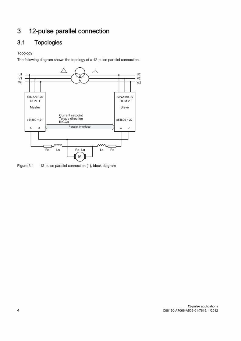
3 12-pulse parallel connection 3.1 Topologies
Topology
The following diagram shows the topology of a 12-pulse parallel connection.
Figure 3-1 12-pulse parallel connection (1), block diagram
12-pulse applications C98130-A7066-A509-01-7619, 1/2012 5
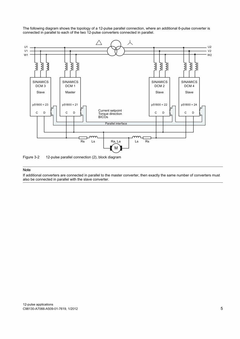
The following diagram shows the topology of a 12-pulse parallel connection, where an additional 6-pulse converter is connected in parallel to each of the two 12-pulse converters connected in parallel.
Figure 3-2 12-pulse parallel connection (2), block diagram
Note If additional converters are connected in parallel to the master converter, then exactly the same number of converters must also be connected in parallel with the slave converter.

12-pulse applications 6 C98130-A7066-A509-01-7619, 1/2012
3.2 Configuration
Not permitted: Operation of several 12-pulse systems on a common 12-pulse transformer
The operation of several 12-pulse systems on a common 12-pulse transformer (see figure below) is not permitted. This can cause balance currents, which can result in a blown fuse or even damage (e.g., thyristor damage).
See the FAQ for 6RA70, SIMOREG DC MASTER and SIMOREG DC MASTER Control Module; "More than one 12-pulse system on a transformer" (http://support.automation.siemens.com/WW/view/en/26041969)
M
M
Figure 3-3 Non-permissible parallel connection
You can, however, connect devices in parallel according to Figure 3-4 Parallel connection of additional SINAMICS DCM devices in 6-pulse operation (Page 7) or Figure 3-5 Parallel connection of additional SINAMICS DCM units in 12-pulse operation (Page 8).

12-pulse applications C98130-A7066-A509-01-7619, 1/2012 7
3.2.1 Power increase with parallel connection In order to increase power, additional SINAMICS DCMs can be connected in parallel.
The options permitted for the parallel connection of SINAMICS DCM devices are described in the chapters "Parallel connection of additional SINAMICS DCM devices in 6-pulse operation (Page 7)" and "Parallel connection of additional SINAMICS DCM units in 12-pulse operation (Page 8)".
3.2.1.1 Parallel connection of additional SINAMICS DCM devices in 6-pulse operation A maximum of 5 additional SINAMICS DCM devices (M1P1, M1P2 and S1P1, S1P2) can be connected in parallel to the SINAMICS DCM devices of the 12-pulse unit (master M1 and slave S1) in 6-pulse operation (for details on the 6-pulse parallel connection, see SINAMICS DCM operating instructions, chapter "Connecting devices in parallel and in series").
The following figure shows an example with one device connected in parallel:
+
-
M
+
-
+
-
+
-
1)
1) Transformer 2) Overvoltage protection 3) Insulation monitoring 4) SINAMICS DCM 5) Smoothing reactor 6) DC motor 7) Line reactor 8) Data exchange (12-pulse parallel
connection) 9) Data exchange (6-pulse parallel connection)
UN = Network supplying rated voltage to converter input Id = Direct current of a partial converter (½ total direct current) Figure 3-4 Parallel connection of additional SINAMICS DCM devices in 6-pulse operation
Advantages and disadvantages of this configuration:
● Advantage: Only one 12-pulse transformer is required.
● Disadvantage: Smoothing reactors are required to avoid a higher current ripple

12-pulse applications 8 C98130-A7066-A509-01-7619, 1/2012
3.2.1.2 Parallel connection of additional SINAMICS DCM units in 12-pulse operation The 12-pulse unit (master M1 and slave S1) can be connected in parallel to a maximum of 2 additional 12-pulse units (M2, S2 and M3, S3) in 12-pulse operation on the DC side, whereby the units connected in parallel adhere to the setpoints of the first master.
You must ensure that each unit is supplied by a separate transformer. If this is not the case, uncontrolled balance currents can occur.
The following figure shows an example with a 12-pulse unit connected in parallel:
1) Transformer 2) Overvoltage protection 3) Insulation monitoring 4) SINAMICS DCM 5) Smoothing reactor 6) DC motor 7) Current setpoint input for example via peer-to-peer
8) Data exchange (12-pulse parallel connection)
UN = Network supplying rated voltage to converter input Id = Direct current of a partial converter (¼ total direct current) Figure 3-5 Parallel connection of additional SINAMICS DCM units in 12-pulse operation
The transformers and smoothing reactors are dimensioned according to points Dimensioning of the converter transformer (Page 10) and Dimensioning of the smoothing reactors (Page 11).
Advantages and disadvantages of this configuration:
● Advantage: Lower current ripple
● Disadvantage: Each unit requires its own 12-pulse transformer

12-pulse applications C98130-A7066-A509-01-7619, 1/2012 9
3.2.2 Prerequisites for the device
Transformer
12-pulse operation is achieved in the network by an additional winding system, electrically swiveled by 30°, belonging to the supplying transformer. Here at least one of the two converters (master or slave) of the 12-pulse system must be supplied via a galvanically isolated voltage (isolation transformer) (see Figure 3-6 Application with three-winding converter transformer (Page 10) and Figure 3-7 Application with isolation transformer (Page 10)).
It is possible to select which of the two converters should be supplied by the voltage leading or lagging by approx. 30° as required.
Converter equipment
Signal connection via parallel interface.
The parallel interface cable between the converters should be as short as possible. The permitted maximum cable length of 15 m should not be used if possible.
The total length of the bus cables for the parallel connector must not exceed 30 m (e.g., maximum 2 x 15 m with a master device with 2 slave devices), whereby the cables must always be as short as possible. If several devices are connected in parallel, the master device must be arranged in the center of the bus connection; the slave devices on either side are distributed as evenly as possible.
Equipotential bonding must be provided and the shield must be connected to ground with a large contact surface on either side.
All SINAMICS DCMs must have the same software version.
Smoothing reactor
Since the instantaneous values of device output voltages differ due to the different phase angle of the line infeed, decoupling via smoothing reactors must be provided upstream of the parallel device connection on the DC voltage side.
Overvoltage protection
Converter equipment which is connected to the line supply via a separate converter transformer must be protected against overvoltages that can occur as a result of line-side switching operations by means of overvoltage protection.
If the converter input is protected by means of open contact gaps during primary-side transformer switching operations, no protective circuit is required at the converter input.
Insulation monitoring
When using non-grounded low-voltage networks, an insulation monitoring device must be used to monitor the insulation. The insulation resistance is continuously monitored, and if the value falls below an adjustable threshold value, this is signaled.
Note It is advisable to measure the armature voltage close to the motor terminals. Voltage drops influenced by smoothing reactors, cabling and bus-bar systems, are automatically taken into account. The voltage applied to the motor terminals is measured. External Voltage sensing is activated by setting p1854 = 1. p51855 is used to scale the analog value, connected via terminals X177.29-30 (AI2). Details can be found in function diagram 6902 of the SINAMICS DCM.

12-pulse applications 10 C98130-A7066-A509-01-7619, 1/2012
3.2.3 Dimensioning of the converter transformer
Application with three-winding converter transformer
+
-
M
+
-
1)
1) Transformer 2) Overvoltage protection 3) Insulation monitoring 4) SINAMICS DCM 5) Smoothing reactor 6) DC motor 8) Current setpoint input UN = Network supplying rated voltage to converter input Id = Direct current of a partial converter (½ total direct current) Figure 3-6 Application with three-winding converter transformer
Transformer: A separate three-winding converter transformer is used to connect to the network of a higher voltage level.
Preferred vector groups for the transformer: Dy5Dd0, Yy0Yd11, uk = 4% to 6%
Transformer type rating: ST = UN × 1,35 × 1,05 × Id × 2
Application with isolation transformer
+
-
M
+
-
1)
1) Transformer 2) Overvoltage protection 4) SINAMICS DCM 5) Smoothing reactor 6) DC motor 7) Line reactor 8) Current setpoint input UN = Network supplying rated voltage to converter input Id = Direct current of a partial converter (½ total direct current) Figure 3-7 Application with isolation transformer
Transformer: When there is a low-voltage rail, an isolation transformer with a voltage transformation ratio of 1:1 is used upstream of a converter for a 30° phase offset.
Suitable vector groups for the transformer: Dy11, Yd11, Dy5, uk = 4% to 6%
Transformer type rating: ST = UN × 1,35 × 1,05 × Id
12-pulse applications C98130-A7066-A509-01-7619, 1/2012 11
NOTICE If converter equipment is connected in parallel in order to increase the current (parallel connection of additional max. 5 devices per 6-pulse branch is supported), a line reactor must be connected upstream of each converter unit with min. 2% uD in order to decouple the converter equipment. In order to ensure symmetrical current distribution in the parallel converter units, the lowest possible deviation of the impedance values of the individual line reactors is required. In practice, a 3% difference can be achieved at a reasonable cost. The additional voltage drop in the line reactors must be taken into account during the configuration. If converters are used which do not have any arm fuses and 4Q operation is possible at the same time, every converter is to be supplied with a fuse on the DC side which has been dimensioned according to its output current.
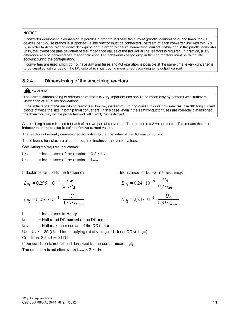
3.2.4 Dimensioning of the smoothing reactors
WARNING The correct dimensioning of smoothing reactors is very important and should be made only by persons with sufficient knowledge of 12-pulse applications. If the inductance of the smoothing reactors is too low, instead of 60° long current blocks, this may result in 30° long current blocks of twice the size in both partial converters. In this case, even if the semiconductor fuses are correctly dimensioned, the thyristors may not be protected and will quickly be destroyed.
A smoothing reactor is used for each of the two partial converters. The reactor is a 2-value reactor. This means that the inductance of the reactor is defined for two current values.
The reactor is thermally dimensioned according to the rms value of the DC reactor current.
The following formulas are used for rough estimates of the reactor values.
Calculating the required inductance:
LD1 = Inductance of the reactor at 0.2 × Idn LD1 = Inductance of the reactor at Idmax Inductance for 50 Hz line frequency: Inductance for 60 Hz line frequency:
L = Inductance in Henry Idn = Half rated DC current of the DC motor Idmax = Half maximum current of the DC motor Udi = UN × 1,35 (UN = Line supplying rated voltage, Udi ideal DC voltage) Condition: 3,5 × LD2 ≥ LD1 If the condition is not fulfilled, LD2 must be increased accordingly. The condition is satisfied when Idmax < 2 × Idn
12-pulse applications 12 C98130-A7066-A509-01-7619, 1/2012
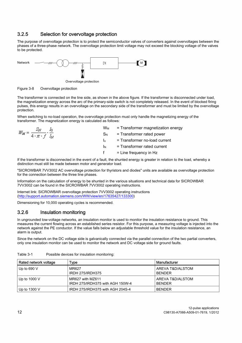
3.2.5 Selection for overvoltage protection The purpose of overvoltage protection is to protect the semiconductor valves of converters against overvoltages between the phases of a three-phase network. The overvoltage protection limit voltage may not exceed the blocking voltage of the valves to be protected.
M
Figure 3-8 Overvoltage protection
The transformer is connected on the line side, as shown in the above figure. If the transformer is disconnected under load, the magnetization energy across the arc of the primary-side switch is not completely released. In the event of blocked firing pulses, this energy results in an overvoltage on the secondary side of the transformer and must be limited by the overvoltage protection.
When switching to no-load operation, the overvoltage protection must only handle the magnetizing energy of the transformer. The magnetization energy is calculated as follows:
WM = Transformer magnetization energy SN = Transformer rated power Io = Transformer no-load current IN = Transformer rated current
f = Line frequency in Hz If the transformer is disconnected in the event of a fault, the shunted energy is greater in relation to the load, whereby a distinction must still be made between motor and generator load.
"SICROWBAR 7VV3002 AC overvoltage protection for thyristors and diodes" units are available as overvoltage protection for the connection between the three line phases.
Information on the calculation of energy to be shunted in the various situations and technical data for SICROWBAR 7VV3002 can be found in the SICROWBAR 7VV3002 operating instructions.
Internet link: SICROWBAR overvoltage protection 7VV3002 operating instructions (http://support.automation.siemens.com/WW/view/en/17635427/133300)
Dimensioning for 10,000 operating cycles is recommended.
3.2.6 Insulation monitoring In ungrounded low-voltage networks, an insulation monitor is used to monitor the insulation resistance to ground. This measures the current flowing across an established series resistor. For this purpose, a measuring voltage is injected into the network against the PE conductor. If the value falls below an adjustable threshold value for the insulation resistance, an alarm is output.
Since the network on the DC voltage side is galvanically connected via the parallel connection of the two partial converters, only one insulation monitor can be used to monitor the network and DC voltage side for ground faults.
Table 3-1 Possible devices for insulation monitoring:
Rated network voltage Type Manufacturer Up to 690 V MR627
IRDH 275/IRDH375 AREVA T&D/ALSTOM BENDER
Up to 1000 V MR627 with MZ611 IRDH 275/IRDH375 with AGH 150W-4
AREVA T&D/ALSTOM BENDER
Up to 1300 V IRDH 275/IRDH375 with AGH 204S-4 BENDER

12-pulse applications C98130-A7066-A509-01-7619, 1/2012 13
3.3 Commissioning In principle, all converters should be commissioned as described in the Commissioning chapter of the SINAMICS DCM DC Converter operating instructions.
The settings in chapter Specifying the operating mode (Page 13) and chapter Additional parameter settings (Page 14) should be made before commissioning (chapter Carrying out commissioning (Page 14)).
To make the settings, use
● BOP20 operator panel
● AOP30 operator panel: Parameter list
● STARTER commissioning tool: Expert list.
3.3.1 Specifying the operating mode Two operating modes are supported:
Operation with firing angle interface (p51799 = 0 or p51799 = 21)
● Master (SINAMICS DCM 1): Closed-loop speed control, armature current closed-loop control and field current closed-loop control
● Slave (SINAMICS DCM 2): Armature current closed-loop control
The master determines the theoretical firing angle and transfers it to its own gating unit and to the gating unit of the slave. Both partial converters synchronize to their own network and form their own firing points. However, both the master and the slave have their own current controller which intervenes to make any corrections.
Operation with current setpoint interface (p51799 = 22)
● Master (SINAMICS DCM 1): Closed-loop speed control, armature current closed-loop control and field current closed-loop control
● Slave (SINAMICS DCM 2): Armature current closed-loop control
The master determines the armature current setpoint and transfers this to its own armature current controller and to the armature current controller of the slave. Both partial converters control their own partial current independently.

12-pulse applications 14 C98130-A7066-A509-01-7619, 1/2012
3.3.2 Additional parameter settings
Table 3-2 Parameter settings on the master converter and on the slave converter:
Parameter Master Slave or parallel devices p51799 Mode of operation 0, 21 or 22 The same as on the master p51800 Position in the topology 21 (12-pulse master) 22 (12-pulse slave)
23 (devices connected in parallel to the master) 24 (devices connected in parallel to the slave)
p51801 Amount of send data Application-specific Application-specific p51802 Number of powersections ≥2 2 p51803 n+m mode 0 0 p51804[..] Send data Application-specific Application-specific p51805 Bus terminator 0 or 1 1) 0 or 1 1) p51806 Station address Unique address Unique address p51807 Telegram failure time 0.1 s 0.1 s p50082 Field operating mode ≠ 0 0 (no field) p50076[..] Reduction in rated device DC current Application-specific The same as on the master p50078[..] Rated value for supply voltage Application-specific The same as on the master p50100 Rated motor current Rated motor
current/number of SINAMICS DCMs
The same as on the master
p50357 Threshold for interrupted tachometer Application-specific 100% (tachometer interruption monitoring not active)
1) = 1 on the two outermost devices (= at both physical ends of the bus cable) = 0 on all other devices
3.3.3 Carrying out commissioning Carry out commissioning on the master converter and on the slave converter as described in the SINAMICS DCM DC Converter operating instructions:
● When commissioning with the BOP20 operator panel: Perform commissioning steps
● When commissioning with the AOP30 operator panel: Execute "Drive commissioning" menu command
● When commissioning with the STARTER commissioning tool: Start the "Configure drive unit" wizard

12-pulse applications C98130-A7066-A509-01-7619, 1/2012 15
3.3.4 Optimization runs The optimization runs should only be carried out on the master converter. The slave converters must be connected and ready for operation at this point.
The optimization run for the armature current closed-loop control (p50051 = 25) may only be carried out if
● the smoothing reactor is dimensioned correctly (see chapter Dimensioning of the smoothing reactors (Page 11)) and
● the parameter for the rated motor current (p50100) is set correctly.
During this optimization run, the firing angle is shifted in the Alpha-G direction until either 90% of the rated motor current is reached or until the rated device current (r50072[1]) is reached, depending on which case occurs earlier.
WARNING If the inductance of the smoothing reactor is too low at this current, the thyristors may be destroyed.
The optimization run for the armature current closed-loop control (p50051 = 25) sets the following parameters on the master converter:
Parameter Master Slave or parallel devices p50110 Armature resistance Ra Actual armature resistance × half the number
of SINAMICS DCMs The same as on the master
p50111 Armature inductance La
Actual armature inductance × half the number of SINAMICS DCMs
The same as on the master
p51591 La reduction factor - The same as on the master p51596 Suction resistance Rs Actual suction resistance × half the number of
SINAMICS DCMs The same as on the master
p51594 Suction inductance Ls Actual suction inductance × half the number of SINAMICS DCMs
The same as on the master
p51595 Ls reduction factor - The same as on the master p50155 Kp armature current
controller - The same as on the master
p50156 Tn armature current controller
- The same as on the master
In many cases, the optimization run is missing the criteria for the correct distribution of the total inductance between the armature inductance and the suction inductance, especially if the two inductances differ considerably. This is why it is recommended that these parameters are always checked and, if necessary, set manually to the correct values.
Following this, the parameter settings from the above table must be transferred manually from the master converter to the slave converter.
12-pulse applications 16 C98130-A7066-A509-01-7619, 1/2012
4 12-pulse series connection 4.1 Topologies
4.1.1 12-pulse series connection of two SINAMICS DCMs
Topology
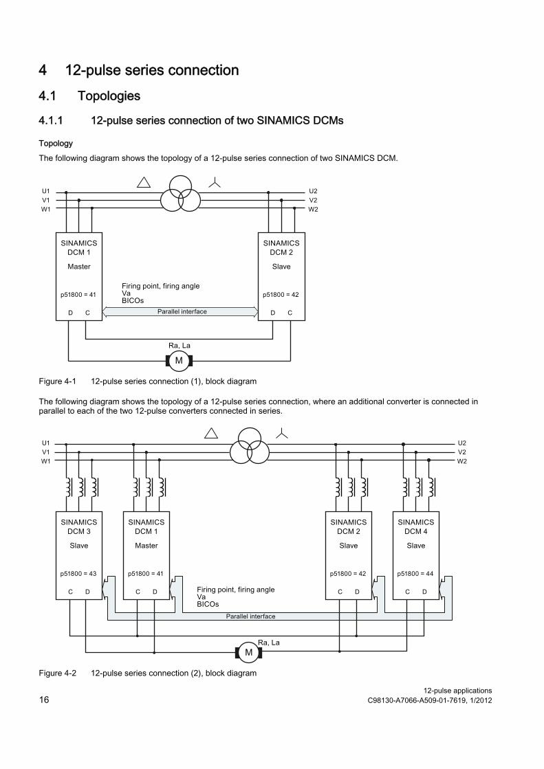
The following diagram shows the topology of a 12-pulse series connection of two SINAMICS DCM.
Figure 4-1 12-pulse series connection (1), block diagram
The following diagram shows the topology of a 12-pulse series connection, where an additional converter is connected in parallel to each of the two 12-pulse converters connected in series.
Figure 4-2 12-pulse series connection (2), block diagram
12-pulse applications C98130-A7066-A509-01-7619, 1/2012 17
Operating modes
There are 2 operating modes:
● Operation with the same firing pulses (p51799 = 41): Both partial converters are fired at precisely the same instant. The master calculates the firing point and this is transferred to the slave via the parallel interface. Synchronization to the line supply is exclusively performed by the master. The slave must be connected to the line supply with the same phase sequence as the master.
● Operation with sequence control (p51799 = 42): Both partial converters synchronize to the line supply and generate their own firing points. The firing angle for the master and the firing angle for the slave are calculated by the master and the firing angle and the torque direction for the slave are transferred to the slave via the parallel interface. The firing angle for the master and slave are generated so that the reactive power load of the line supply is as low as possible. This is the case if one of the two partial converters is at a control limit and the other carries-out the closed-loop control. This type of closed-loop control is only possible for continuous current. Operation with the same firing points is automatically selected in the discontinuous (pulsating) current range.
Remark
If the two partial converters operate in the following mode, the current ripple is significantly higher than operation with the same firing angle. In this case, the current ripple approximately corresponds to that for 6-pulse operation. Especially in older motors, under certain circumstances this ripple can cause problems (for example, during commutation).
Therefore, a conscious decision must be made:
● low ripple, but no reduction of the reactive power: → operation with the same firing pulses (p51799 = 41)
● low reactive power, but no reduction of the ripple: → operation with following control (p51799 = 42)
Note
The power unit of the slave converter must be connected to the 12-pulse transformer so that its phases lag the phases of the line supply at the master by 30°. The phase sequence must be the same.
12-pulse applications 18 C98130-A7066-A509-01-7619, 1/2012
4.1.2 12-pulse series connection: controlled converter + uncontrolled converter
Topology
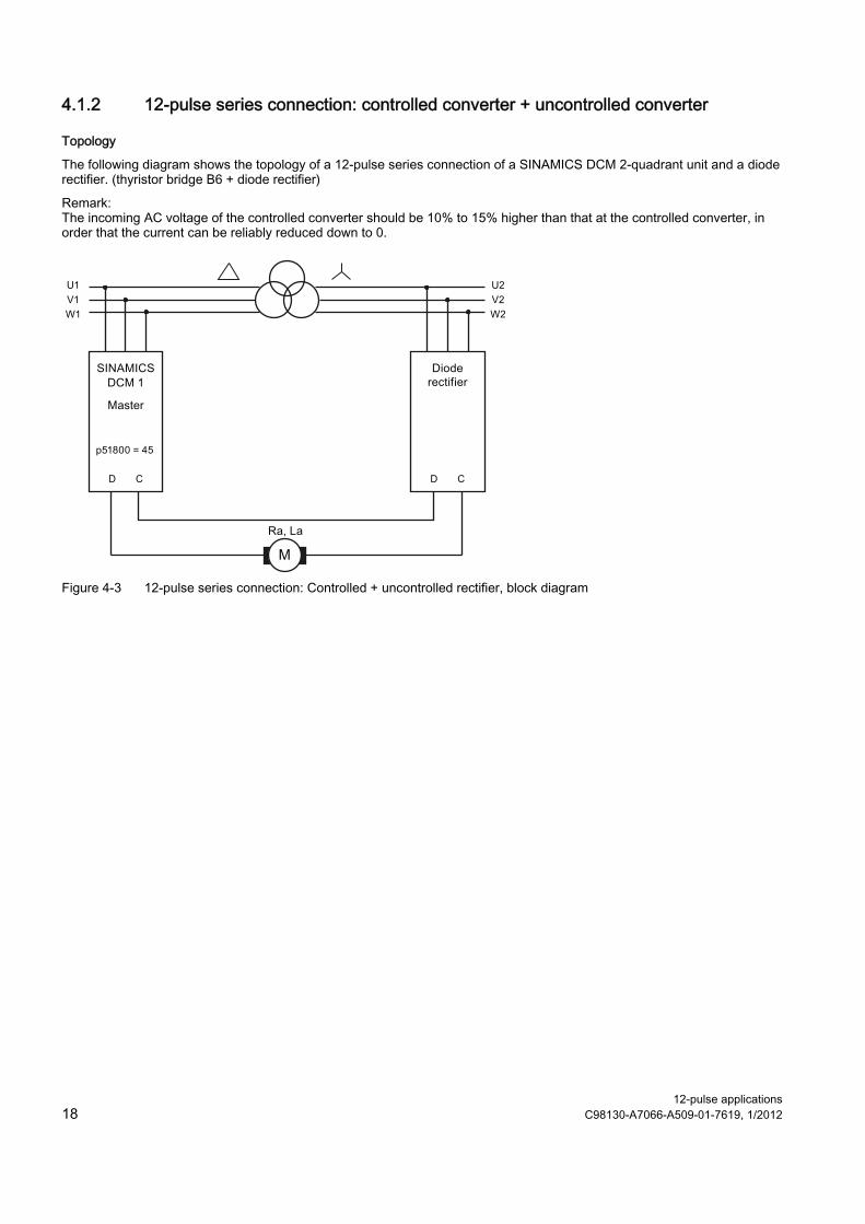
The following diagram shows the topology of a 12-pulse series connection of a SINAMICS DCM 2-quadrant unit and a diode rectifier. (thyristor bridge B6 + diode rectifier)
Remark: The incoming AC voltage of the controlled converter should be 10% to 15% higher than that at the controlled converter, in order that the current can be reliably reduced down to 0.
Figure 4-3 12-pulse series connection: Controlled + uncontrolled rectifier, block diagram

12-pulse applications C98130-A7066-A509-01-7619, 1/2012 19
4.2 Configuration
4.2.1 Power increase with parallel connection Additional devices can be connected in parallel to the SINAMICS DCM 12-pulse series master device and the 12-pulse series slave device to increase the output current.
The maximum possible configuration is 2 groups in series, each consisting of 3 devices connected in parallel.
Suggested circuit:
+
-
M
+
-
+
-
+
-
1)
1) Transformer 2) Overvoltage protection 3) Insulation monitoring 4) SINAMICS DCM master 5) SINAMICS DCM slave 6) DC motor 7) Line reactor 8) Parallel interface 9) Symmetry resistor UN = Network supplying rated voltage to converter input Id = Direct current through SINAMICS DCM devices and motor Figure 4-4 Connection of additional SINAMICS DCM devices in 6-pulse operation
4.2.2 Prerequisites for the device
Transformer
12-pulse operation is achieved in the network by an additional winding system, electrically swiveled by 30°, belonging to the supplying transformer. Here at least one of the two converters (master or slave) of the 12-pulse system must be supplied via a galvanically isolated voltage (isolation transformer) (see Figure 4-5 Converter transformer dimensioning at higher voltage level (Page 20) and Figure 4-6 Converter transformer dimensioning at low voltage (Page 21)).
NOTICE Both converters must be supplied with a clockwise rotation field. In addition, it is important to ensure that the three-phase current system on the slave device lags behind that of the master device by 30°. This phase allocation may need to be checked by taking a measurement.
Converter equipment
SINAMICS DCM software version V1.2 or higher.
All SINAMICS DCMs must have the same software version.
12-pulse applications 20 C98130-A7066-A509-01-7619, 1/2012
Symmetry resistor
With a 12-pulse series connection, symmetry resistors must be connected in parallel to the individual converters connected in series, through which at least one current in the amount of the maximum thyristor reverse current flows. This ensures that, in the range of the small armature current or when armature current = 0, the total armature voltage is distributed symmetrically to both individual devices.
As a result of the activation of the thyristors with long pulses, an increased reverse current may flow. The symmetry resistors must be dimensioned so that at maximum armature voltage, a cross-current of at least 100 mA flows. With the parallel connection of a device, the cross-current at maximum voltage should be at least 200 mA and for two devices at least 300 mA.
Overvoltage protection
Converter equipment which is connected to the network via a separate converter transformer must be protected against overvoltages that can occur as a result of line-side switching operations by means of overvoltage protection.
If the converter input is protected by means of open contact gaps during primary-side transformer switching operations, no protective circuit is required at the converter input.
Insulation monitoring
When using non-grounded low-voltage networks, an insulation monitoring device must be used to monitor the insulation. The insulation resistance is continuously monitored, and if the value falls below an adjustable threshold value, this is signaled.
Usage of external armature voltage measurement If the armature voltage is to be measured externally, connected via X177.29-30 (AI2) and activated by setting p1854 = 1, please note the following. Upon activation of serial connection mode, the SINAMICS DCM Master automatically adds the measured armature voltage of the SINAMICS DCM serial slave, to the voltage value. If a diode bridge is used as serial slave, the voltage value beeing added can be influenced by p51798.
Currently it is not possible to disable this feature.
4.2.3 Dimensioning of the converter transformer
Application with three-winding converter transformer
+
-
M
+
-
1)
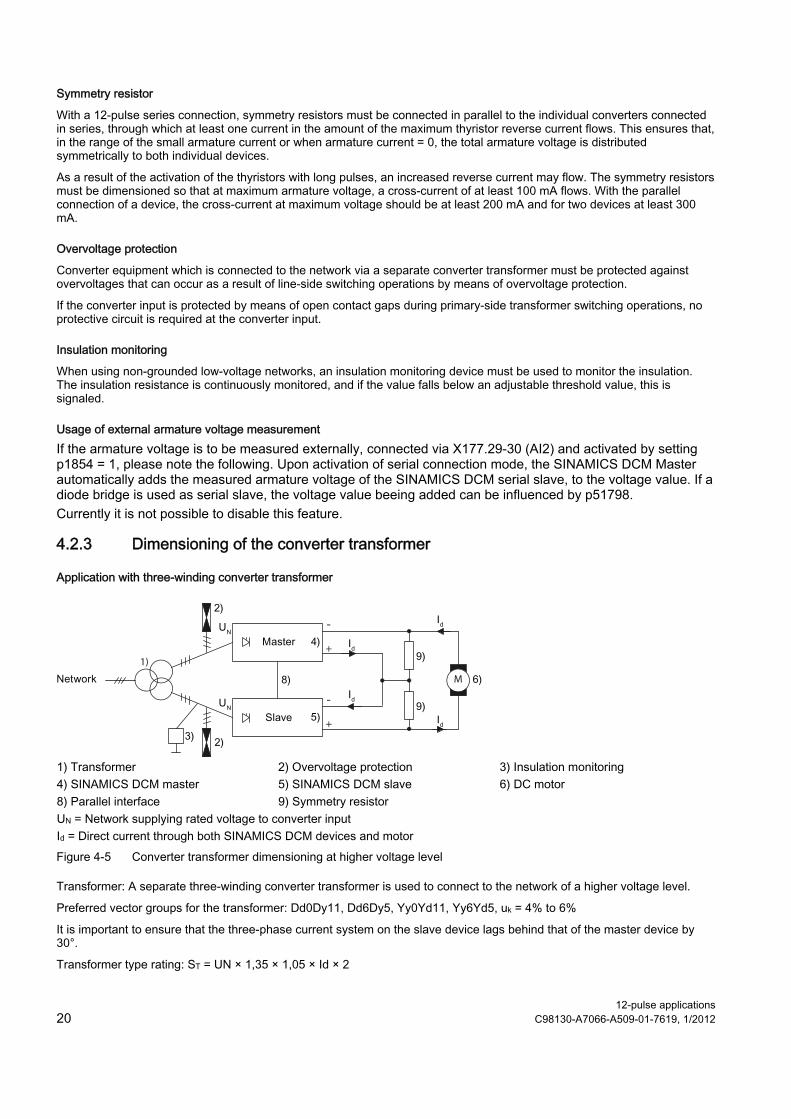
1) Transformer 2) Overvoltage protection 3) Insulation monitoring 4) SINAMICS DCM master 5) SINAMICS DCM slave 6) DC motor 8) Parallel interface 9) Symmetry resistor UN = Network supplying rated voltage to converter input Id = Direct current through both SINAMICS DCM devices and motor Figure 4-5 Converter transformer dimensioning at higher voltage level
Transformer: A separate three-winding converter transformer is used to connect to the network of a higher voltage level.
Preferred vector groups for the transformer: Dd0Dy11, Dd6Dy5, Yy0Yd11, Yy6Yd5, uk = 4% to 6%
It is important to ensure that the three-phase current system on the slave device lags behind that of the master device by 30°.
Transformer type rating: ST = UN × 1,35 × 1,05 × Id × 2

12-pulse applications C98130-A7066-A509-01-7619, 1/2012 21
Application with isolation transformer
+
-
M
+
-
1)
1) Transformer 2) Overvoltage protection 4) SINAMICS DCM master 5) SINAMICS DCM slave 6) DC motor 7) Line reactor 8) Parallel interface 9) Symmetry resistor UN = Network supplying rated voltage to converter input Id = Direct current through both SINAMICS DCM devices and motor Figure 4-6 Converter transformer dimensioning at low voltage
Transformer: When there is a low-voltage rail, an isolation transformer with a voltage transformation ratio of 1:1 is used upstream of the slave converter for a 30° phase offset.
Suitable vector groups for the transformer: Dy11, Yd11, uk = 4% to 6%
Transformer type rating: ST = UN × 1,35 × 1,05 × Id
NOTICE If converter equipment is connected in parallel in order to increase the current (parallel connection of additional max. 2 devices per 6-pulse branch is possible), a line reactor must be connected upstream of each converter unit with min. 2% uD in order to decouple the converter equipment. In order to ensure symmetrical current distribution in the parallel converter units, the lowest possible deviation of the impedance values of the individual line reactors is required. In practice, a 3% difference can be reached at a reasonable cost. The additional voltage drop in the line reactors must be taken into account during the configuration. If converters are used which do not have any arm fuses and 4Q operation is possible at the same time, every converter is to be supplied with a fuse on the DC side which has been dimensioned according to its output current.

12-pulse applications 22 C98130-A7066-A509-01-7619, 1/2012
4.2.4 Voltage limits The output voltage of a 12-pulse series system is set by the insulation strength and the semiconductor reverse voltages of the individual devices.
Devices with 690, 830 and 950 VAC have the same control module, i.e., the insulation against ground is set to 950 VAC in all three devices. However, this voltage cannot be fully utilized because series connection can cause a much higher voltage against ground in the system in the event of a ground fault. In addition, the faulty functioning of the symmetry resistors or of one of the converters can, for example, result in an impermissible increase in the thyristor reverse voltages.
For this reason, the maximum input voltage depending on the device types (according to the following table) must not be exceeded by any device:
MLFB device type
Max. input voltage [Vrms]
MLFB device type
Max. input voltage [Vrms]
MLFB device type
Max. input voltage [Vrms]
6RA8013-6DV62 2 x 300 6RA8078-6FV62 2 x 300 6RA8091-6FS22 2 x 300 6RA8013-6FV62 2 x 300 6RA8081-6DS22 2 x 300 6RA8091-6FV62 2 x 300 6RA8018-6DV62 2 x 300 6RA8081-6DV62 2 x 300 6RA8093-4DS22 2 x 300 6RA8018-6FV62 2 x 300 6RA8081-6GS22 2 x 300 6RA8093-4DV62 2 x 300 6RA8025-6DS22 2 x 300 6RA8081-6GV62 2 x 300 6RA8093-4GS22 2 x 300 6RA8025-6DV62 2 x 300 6RA8082-6FS22 2 x 300 6RA8093-4GV62 2 x 300 6RA8025-6FS22 2 x 300 6RA8082-6FV62 2 x 300 6RA8093-4KS22 2 x 500 6RA8025-6FV62 2 x 300 6RA8085-6DS22 2 x 300 6RA8093-4KV62 2 x 500 6RA8025-6GS22 2 x 300 6RA8085-6DV62 2 x 300 6RA8093-4LS22 2 x 500 6RA8025-6GV62 2 x 300 6RA8085-6FS22 2 x 300 6RA8093-4LV62 2 x 500 6RA8028-6DS22 2 x 300 6RA8085-6FV62 2 x 300 6RA8095-4DS22 2 x 300 6RA8028-6DV62 2 x 300 6RA8085-6GS22 2 x 300 6RA8095-4DV62 2 x 300 6RA8028-6FS22 2 x 300 6RA8085-6GV62 2 x 300 6RA8095-4GS22 2 x 300 6RA8028-6FV62 2 x 300 6RA8086-6KS22 2 x 345 6RA8095-4GV62 2 x 300 6RA8031-6DS22 2 x 300 6RA8086-6KV62 2 x 345 6RA8095-4KS22 2 x 500 6RA8031-6DV62 2 x 300 6RA8087-6DS22 2 x 300 6RA8095-4KV62 2 x 500 6RA8031-6FS22 2 x 300 6RA8087-6DV62 2 x 300 6RA8095-4LS22 2 x 500 6RA8031-6FV62 2 x 300 6RA8087-6FS22 2 x 300 6RA8095-4LV62 2 x 500 6RA8031-6GS22 2 x 300 6RA8087-6FV62 2 x 300 6RA8096-4GS22 2 x 300 6RA8031-6GV62 2 x 300 6RA8087-6GS22 2 x 300 6RA8096-4GV62 2 x 300 6RA8075-6DS22 2 x 300 6RA8087-6GV62 2 x 300 6RA8096-4MS22 2 x 500 6RA8075-6DV62 2 x 300 6RA8088-6LS22 2 x 500 6RA8096-4MV62 2 x 500 6RA8075-6FS22 2 x 300 6RA8088-6LV62 2 x 500 6RA8097-4GS22 2 x 300 6RA8075-6FV62 2 x 300 6RA8090-6GS22 2 x 300 6RA8097-4GV62 2 x 300 6RA8075-6GS22 2 x 300 6RA8090-6GV62 2 x 300 6RA8097-4KS22 2 x 500 6RA8075-6GV62 2 x 300 6RA8090-6KS22 2 x 500 6RA8097-4KV62 2 x 500 6RA8078-6DS22 2 x 300 6RA8090-6KV62 2 x 500 6RA8098-4DS22 2 x 300 6RA8078-6DV62 2 x 300 6RA8091-6DS22 2 x 300 6RA8098-4DV62 2 x 300 6RA8078-6FS22 2 x 300 6RA8091-6DV62 2 x 300 6RA8000-0MV62 2 x 500
If higher input voltages are present, SINAMICS DC MASTER Control Modules should be used in connection with suitable external power units in order to achieve the required proof voltage. The corresponding systems are available on request.

12-pulse applications C98130-A7066-A509-01-7619, 1/2012 23
4.2.5 Selection for overvoltage protection The purpose of overvoltage protection is to protect the semiconductor valves of converters against overvoltages between the phases of a three-phase network. The overvoltage protection limit voltage may not exceed the blocking voltage of the valves to be protected.
M
Figure 4-7 Overvoltage protection
The transformer is connected on the line side, as shown in the above figure. If the transformer is disconnected under load, the magnetization energy across the arc of the primary-side switch is not completely released. In the event of blocked firing pulses, this energy results in an overvoltage on the secondary side of the transformer and must be limited by the overvoltage protection.
When switching to no-load operation, the overvoltage protection must only handle the magnetizing energy of the transformer. The magnetization energy is calculated as follows:
WM = Transformer magnetization energy SN = Transformer rated power Io = Transformer no-load current IN = Transformer rated current
f = Line frequency in Hz If the transformer is disconnected in the event of a fault, the shunted energy is greater in relation to the load, whereby a distinction must still be made between motor and generator load.
"SICROWBAR 7VV3002 AC overvoltage protection for thyristors and diodes" units are available as overvoltage protection for the connection between the three line phases.
Information on the calculation of energy to be shunted in various operations and technical data for SICROWBAR 7VV3002 can be found in the SICROWBAR 7VV3002 operating instructions.
Internet link: SICROWBAR overvoltage protection 7VV3002 operating instructions (http://support.automation.siemens.com/WW/view/en/17635427/133300)
Dimensioning for 10,000 operating cycles is recommended.
4.2.6 Insulation monitoring In ungrounded low-voltage networks, an insulation monitor is used to monitor the insulation resistance to ground. This measures the current flowing across an established series resistor. For this purpose, a measuring voltage is injected into the network against the PE conductor. If the value falls below an adjustable threshold value for the insulation resistance, an alarm is output.
Since the network on the DC voltage side is galvanically connected via the parallel connection of the two partial converters, only one insulation monitor can be used to monitor the network and DC voltage side for ground faults.
Table 4-1 Possible devices for insulation monitoring:
Rated network voltage Type Manufacturer Up to 690 V MR627
IRDH 275/IRDH375 AREVA T&D/ALSTOM BENDER
Up to 1000 V MR627 with MZ611 IRDH 275/IRDH375 with AGH 150W-4
AREVA T&D/ALSTOM BENDER
Up to 1300 V IRDH 275/IRDH375 with AGH 204S-4 BENDER

12-pulse applications 24 C98130-A7066-A509-01-7619, 1/2012
4.3 Commissioning In principle, all converters should be commissioned as described in the Commissioning chapter of the SINAMICS DCM DC Converter operating instructions.
The settings in chapter Additional parameter settings (Page 24) should be made before commissioning (chapter Carrying out commissioning (Page 25)).
To make the settings, use
● BOP20 operator panel
● AOP30 operator panel: Parameter list
● STARTER commissioning tool: Expert list.
4.3.1 Additional parameter settings Parameter settings on the master converter and on the slave converter.
Table 4-2 For 12-pulse series connection of SINAMICS DCM converters:
Parameter Master Slave or parallel devices p51799 Mode of operation 0, 41 or 42 The same as on the master p51800 Position in the topology 41 (Master) 42 (Slave)
43 (devices connected in parallel to the master) 44 (devices connected in parallel to the slave)
p51801 Amount of send data Application-specific Application-specific p51802 Number of powersections 2 2 p51803 n+m mode 0 0 p51804[..] Send data Application-specific Application-specific p51805 Bus terminator 0 or 1 1) 0 or 1 1) p51806 Station address Unique address Unique address p51807 Telegram failure time 0.1 s 0.1 s p50082 Field operating mode ≠ 0 0 (no field) p50076[..] Reduction in rated device DC current Application-specific The same as on the master p50078[..] Rated value for supply voltage Application-specific The same as on the master p50100 Rated motor current Rated motor current/half
the number of SINAMICS DCMs
The same as on the master
p50101 Armature voltage Total armature voltage (rated value according to motor rate plate)
The same as on the master
1) = 1 on the two outermost devices (= at both physical ends of the bus cable) = 0 on all other devices
12-pulse applications C98130-A7066-A509-01-7619, 1/2012 25
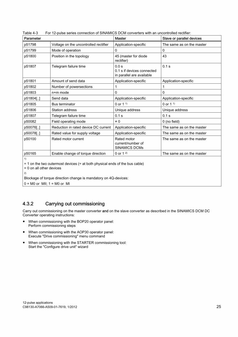
Table 4-3 For 12-pulse series connection of SINAMICS DCM converters with an uncontrolled rectifier: Parameter Master Slave or parallel devices p51798 Voltage on the uncontrolled rectifier Application-specific The same as on the master p51799 Mode of operation 0 0 p51800 Position in the topology 45 (master for diode
rectifier) 43
p51807 Telegram failure time 0.0 s 0.1 s if devices connected in parallel are available
0.1 s
p51801 Amount of send data Application-specific Application-specific p51802 Number of powersections 1 1 p51803 n+m mode 0 0 p51804[..] Send data Application-specific Application-specific p51805 Bus terminator 0 or 1 1) 0 or 1 1) p51806 Station address Unique address Unique address p51807 Telegram failure time 0.1 s 0.1 s p50082 Field operating mode ≠ 0 0 (no field) p50076[..] Reduction in rated device DC current Application-specific The same as on the master p50078[..] Rated value for supply voltage Application-specific The same as on the master p50100 Rated motor current Rated motor
current/number of SINAMICS DCMs
The same as on the master
p50165 Enable change of torque direction 0 or 1 2) The same as on the master 1) = 1 on the two outermost devices (= at both physical ends of the bus cable) = 0 on all other devices 2)
Blockage of torque direction change is mandatory on 4Q-devices: 0 = M0 or MII; 1 = M0 or MI
4.3.2 Carrying out commissioning Carry out commissioning on the master converter and on the slave converter as described in the SINAMICS DCM DC Converter operating instructions:
● When commissioning with the BOP20 operator panel: Perform commissioning steps
● When commissioning with the AOP30 operator panel: Execute "Drive commissioning" menu command
● When commissioning with the STARTER commissioning tool: Start the "Configure drive unit" wizard
12-pulse applications 26 C98130-A7066-A509-01-7619, 1/2012
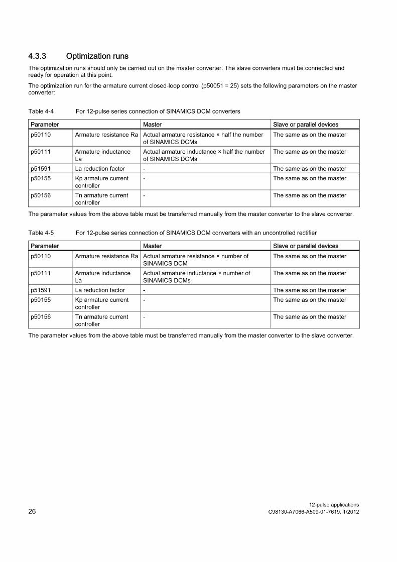
4.3.3 Optimization runs The optimization runs should only be carried out on the master converter. The slave converters must be connected and ready for operation at this point.
The optimization run for the armature current closed-loop control (p50051 = 25) sets the following parameters on the master converter:
Table 4-4 For 12-pulse series connection of SINAMICS DCM converters
Parameter Master Slave or parallel devices p50110 Armature resistance Ra Actual armature resistance × half the number
of SINAMICS DCMs The same as on the master
p50111 Armature inductance La
Actual armature inductance × half the number of SINAMICS DCMs
The same as on the master
p51591 La reduction factor - The same as on the master p50155 Kp armature current
controller - The same as on the master
p50156 Tn armature current controller
- The same as on the master
The parameter values from the above table must be transferred manually from the master converter to the slave converter.
Table 4-5 For 12-pulse series connection of SINAMICS DCM converters with an uncontrolled rectifier
Parameter Master Slave or parallel devices p50110 Armature resistance Ra Actual armature resistance × number of
SINAMICS DCM The same as on the master
p50111 Armature inductance La
Actual armature inductance × number of SINAMICS DCMs
The same as on the master
p51591 La reduction factor - The same as on the master p50155 Kp armature current
controller - The same as on the master
p50156 Tn armature current controller
- The same as on the master
The parameter values from the above table must be transferred manually from the master converter to the slave converter.
12-pulse applications C98130-A7066-A509-01-7619, 1/2012 27
5 Switchover of the power unit topology - option S50
Note The SINAMICS DCM can only be equipped or retrofitted with option S50 in the factory.
In certain applications, it is necessary to switch between two different power unit topologies (such as between 12-pulse parallel connection and 12-pulse series connection) during operation by means of a command.
SINAMICS DCM converters with option S50 provide the control for this purpose. The actual switch between power unit topologies is performed with external contactors.
The detailed functionality and a recommended interconnection are provided in function block diagram 9360 in the SINAMICS DCM List Manual. For further inquires and information on this subject, contact your local sales representative or SIEMENS customer support.
Prerequisites for the switchover of the power unit topology
● All SINAMICS DCMs involved must be equipped with option S50.
● No "n+m" mode may be used.
● The function of the "parallel switching master" must remain on the same SINAMICS DCM in both power unit topologies.
● SINAMICS DCM software version V1.3 or higher.
● All SINAMICS DCMs must have the same software version.
Parameter assignment
The following parameters must be set separately for the two power unit topologies:
Power unit topology 1 p51799 Mode of operation of the armature converter p51800 Position of the power unit in the topology p51802 Number of active power units
Power unit topology 2 p51794 Mode of operation of the armature converter p51795 Position of the power unit in the topology p51802 Number of active power units
Selection of the required power unit topology and function
The required power unit topology can be selected on the parallel switching master with a BICO input (see p51790) and is passed on internally to the parallel switching slaves. The p51790 setting on the parallel switching slaves has no effect.
If the required power unit topology does not match the currently active topology, a switchover is triggered. Switchovers that have been started are carried out in full, and only then is a further switchover possible.
Control of the contactors for the power unit topology
The contactors are controlled via two BICO outputs (see r53312.0 and r53312.1) on the parallel switching master, and these generate the selected power unit topology. The corresponding BICO outputs on the parallel switching slaves must not be used.
The contactors can only be switched in a de-energized state.
During power up of the SINAMICS DCM, both power unit topologies are switched off. After this, the two power unit topologies are mutually locked inside the device so that only one power unit topology can be switched on. For safety reasons, the contactors must also be mutually locked via auxiliary contacts as shown in function block diagram 9360.
Feedback from the active power unit topology
The active power unit topology is queried on the parallel switching master using a BICO input (see p51791). The corresponding BICO input on the parallel switching slave has no effect.
12-pulse applications 28 C98130-A7066-A509-01-7619, 1/2012
Switchover
The switchover of power unit topology is permitted in every operating state.
In the event of a switchover to the "Operation" state, current reduction, controller disable and firing pulse inhibit are carried out and then the hardware is switched via the contactors. With the feedback from the active power unit topology, the firing pulses and the controller are released again.
During the controller disable and firing pulse inhibit, the SINAMICS DCM is in operating state o1.8.
The duration of the current-free pause during the switchover is influenced primarily by the duration of the hardware switchover by the contactors.
Two times can be set:
p51792 Stabilization time for the feedback from the current power unit topology A change to the feedback signal is only effective if the signal features the new state continuously for longer than the stabilization time. During this time the previous state remains effective.
p51793 Maximum duration of switchover Once this time has elapsed, the feedback from the active power unit topology must match the one requested.
Controller optimization
The two power unit topologies generally require certain parameters, e.g., p50100 (rated motor current), p50110 (armature circuit resistance), p50111 (armature circuit inductance), controller gains, etc., to be set in accordance with the topology.
To do this, the drive data sets (DDS) must be used:
The BICO output for controlling the contactors (r53312.0) must be used as the DDS selection signal (p50820).
The optimization runs or the manual optimization for both power unit topologies must then be carried out separately and the determined values entered in index 0 or index 1 of the appropriate controller parameters.
Recommended procedure:
1. Carry out the optimization of power unit topology 1 in DDS 0 in full
2. Copy DDS 0 to DDS 1 (see p0819)
3. Carry out the optimization of power unit topology 2 in DDS 1
Note A change to the selection of power unit topology during an optimization run leads to the cancelation of the optimization run with fault message F60052.
Monitoring functions
The following properties or states are monitored and in the event of an error result in fault message F60044:
● If power unit topology 2 is selected,
– option S50 must be available
– the master function must be set on the same SINAMICS DCM as for power unit topology 1
– no "n+m" mode may be set (i.e., p51803 must = 0)
● The feedback signal must - except during a switchover of the topology - always match the selection signal.
● The maximum duration of the topology switchover may not exceed the assigned time.
Note If fault message F60044 resulting from a change in the fault reaction (see p02100/p02101) or in the message type (see p02118/p02119) does not lead to the Fault operating state, the SINAMICS DCM remains in operating state o1.8 in the event of a fault.

Trademarks All names identified by ® are registered trademarks of Siemens AG. The remaining trademarks in this publication may be trademarks whose use by third parties for their own purposes could violate the rights of the owner.
Disclaimer of Liability We have reviewed the contents of this publication to ensure consistency with the hardware and software described. Since variance cannot be precluded entirely, we cannot guarantee full consistency. However, the information in this publication is reviewed regularly and any necessary corrections are included in subsequent editions.
Siemens AG Industry Sector Postfach 48 48 90026 NÜRNBERG 12-pulse applications C98130-A7066-A509-01-7619, 1/2012

Operating InstructionsEdition 12/2010
Subject to changeC98130-A7066-A509-01-7619© Siemens AG 2012
Siemens AGIndustry SectorP.O. Box 48 4890026 NUREMBERGGERMANY
www.siemens.com/automation