simultaneous removal of organic matter and...
TRANSCRIPT

SIMULTANEOUS REMOVAL OF ORGANIC MATTER AND
NITRATE FROM AQUEOUS SOLUTIONS USING A
BIO-ELECTROCHEMICAL REACTOR
MOOK WEI TZE
DISSERTATION SUBMITTED IN FULFILMENT
OF THE REQUIREMENTS
FOR THE DEGREE OF MASTER OF ENGINEERING SCIENCE
FACULTY OF ENGINEERING
UNIVERSITY OF MALAYA
KUALA LUMPUR
2014
ii
ABSTRACT
In this research an up-flow undivided bio-electrochemical reactor is used for treating
simultaneously organic matter and nitrates in aqueous solutions. Nitrate elimination
takes place at the cathode while organic substance is oxidized at the anode. The cathode
material is palm shell granular activated carbon coated with a film of
autohydrogenotrophic bacteria. A nano-crystalline PbO2 coated carbon combination
was compared against various anodic materials namely stainless steel, titanium, graphite
and carbon felts. The results showed that PbO2 provided better performance in the
elimination of both pollutants. As such PbO2 was used to study the effects of major
operating parameters such as electrodes spacing, electric current and hydraulic retention
time (HRT) on the performance of the reactor to treat organic matter and nitrates.
Response surface methodology (RSM) was used to evaluate the interactions between
these operating parameters and to optimize the reactor performance. The optimum
conditions for the simultaneous elimination of organic matter and nitrate are an
electrodes spacing of 3.2 cm, electric current of 18 mA and HRT of 45h that provided
organic matter removal efficiency of 83% along with 99% elimination of nitrate. It was
found that the current efficiency (CE) is unaffected by electrode spacing and is higher at
low electric current and HRT. The control of pH is important to minimize nitrite-
nitrogen accumulation.

iii
ABSTRAK
Dalam kajian ini bio-reaktor electrokimia yang aliran atas dan tidak terbahagi telah
digunakan untuk merawat serentak organik dan nitrat dalam berair. Penyingkiran nitrat
berlaku serentak di katod manakala organik dioksidakan pada anod. Bahan katod adalah
daripada kelapa sawit karbon aktif butiran yang disalut dengan lapisan bakteria
autohydrogenotrophic. Komposit karbon bersalut PbO2 nano-kristal telah dibandingkan
dengan pelbagai bahan anodic seperti stainless steel, titanium, grafit dan karbon felts. Ia
didapati bahawa PbO2 memberikan prestasi unggul dalam penyinggiran kedua-dua
bahan pencemar. Oleh itu, PbO2 telah dipilihkan untuk menjalankan kajian tentang
parameter operasi utama seperti jarak elektrod, bekalan elektrik dan hidraulik (HRT).
Kaedah permukaan respons (RSM) adalah bertujuan untuk mengkaji interaksi semua
parameter dan mengoptimumkan prestasi reaktor. Keadaan optimum untuk
penyingkiran serentak bahan organik dan nitrat ialah jarak antara elektrod sebanyak 3.2
cm, arus elektrik sebanyak 18 mA dan HRT sebanyak 45 jam. Dalam keadaan optimum
ini dapat memberikan kecekapan penyingkiran bahan organik sebanyak 83% dan
penyingkiran 99% nitrat. Keberkesanan elektrik (CE) tidak dipengaruhi oleh jarak
elektrod dan ia boleh dipertingkatkan dengan arus electric dan HRT yang rendah.
Pengawalan pH adalah penting untuk mengelakkan pengumpulan nitrit-nitrogen..

iv
ACKNOWLEDGEMENTS
My deep profound appreciation goes to my parents for the tolerance, support and
encouragement I receive from them these years.
I would like to thank my supervisors Prof. Dr. Mohamed Kheireddine Bin Taieb Aroua
and Dr. Mohammed Harun Chakrabarti for their guidance, patience and support
throughout my Master program. I am thankful to Dr. John Low Chee Tong from
University of Southampton for providing nano-crystalline PbO2 electrodes in my
research.
I also would like to thank all my colleagues at Chemical Engineering Department,
University of Malaya and all whom have contributed suggestions to the success of this
research.

v
TABLE OF CONTENTS
Page
Abstract ii
Acknowledgements iv
Table of contents v
List of Figures vii
List of Tables viii
Chapter 1: Introduction
1.1 Introduction 1
1.2 Objectives 4
1.3 Outline of thesis 5
Chapter 2: Literature review
2.1 Conventional treatments 6
2.1.1 Conventional organic matter removal methods 6
2.1.2 Conventional nitrate removal methods 7
2.2 Electrochemical technology 8
2.2.1 Electrochemical oxidation of organic matter 9
2.2.2 Electrochemical reduction of nitrate 11
2.3 Bio-electrochemical technology 13
2.3.1 Bio-electrode 13
2.3.2 Electron transfer mechanism 14
2.3.3 Factors controlling organic matter removal 16
2.3.3.1 Anodic material and surface area 16
2.3.3.2 pH of the electrolyte 17
2.3.4 Factors controlling denitrification 23
2.3.4.1 Cathodic material 23
2.3.4.2 pH of the electrolyte 24
2.3.4.3 Electric current 25
Chapter 3: Materials and methods
3.1 Preparation of electrodes 30
3.2 Reactor configuration 31
3.3 Experimental setup and procedure 32
3.4 Comparison of anode materials 33
3.5 Screening of parameters range 34
3.5.1 Screening of electrodes spacing range 34
3.5.2 Screening of electric current range 34
3.5.3 Screening of HRT range 34
3.6 Analytical methods 34
3.7 Experimental design 35
Chapter 4: Results and discussions
4.1 Comparison of anode material on organic matter and nitrate removal 37
4.2 Screening of different parameters range 41
4.2.1 Screening of electrodes spacing range 41
4.2.2 Screening of electric current range 43
4.2.3 Screening of HRT range 44
4.3 Modeling and parameters optimization using response surface
methodology (RSM)
46

vi
4.3.1 Development of regression equations and statistical analysis 46
4.3.2 Effect of parameters on organic matter and nitrate-nitrogen
removal
50
4.4 Effect of parameters on current efficiency and specific denitrification 54
4.5 Validation of the model 55
Chapter 5: Conclusions and recommendatio
5.1 Conclusion 59
5.2 Recommendation 60
References 61
Appendix A: Calculation porosity of granular activated carbon 77
Appendix B: Calibration curve for HPLC 78
Appendix C: ISI-indexed related journal publications
79

vii
LIST OF FIGURES
Figure Page
Figure 2.1: Reduction of NAD+ and FAD through citric acid cycle 14
Figure 2.2: Direct electron transfer mechanisms in bio-electrodes. (a) Bio-
anodes (b) Bio-cathodes
15
Figure 3.1: Schematic representation of the experimental set-up 33
Figure 4.1: Organic compounds and nitrate-nitrogen removal with different
types of anode material.
39
Figure 4.2: (a) FESEM image of titanium (10,000 x). (b) FESEM image of
lead (IV) oxide (10,000 x). (c) Microscope image of graphite felt
(100 x). (d) Microscope image of carbon felt (100 x). (e) FESEM
image of GAC (10,000x). (f) FESEM image of GAC (100,000x).
40
Figure 4.3: Organic matter and nitrate-nitrogen removal efficiency at different
electrodes spacing.
42
Figure 4.4: Organic matter and nitrate-nitrogen removal efficiency at different
electric current
44
Figure 4.5: Organic matter and nitrate-nitrogen removal efficiency at different
HRT
46
Figure 4.6: Response surface plot for organic matter removal (i) interaction
between electrodes spacing and electric current. (ii) interaction
between HRT and electric current.
51
Figure 4.7: Response surface plot for nitrate-nitrogen removal: interaction
between electric current and HRT.
52
Figure 4.8: Response surface plot for nitrite-nitrogen concentration (i)
interaction between electrodes spacing and HRT. (ii) interaction
between electrode spacing and electric current.
53
Figure 4.9: CE and SD at different sets of electrodes spacing, electric current
and HRT.
55
Figure B1: Calibration curve for nitrate-nitrogen standards obtained by HPLC 78
Figure B2: Calibration curve for nitrite-nitrogen standards obtained by HPLC 78

viii
LIST OF TABLES
Table Page
Table 2.1: General mechanism of direct anodic oxidation of organic
compounds
10
Table 2.2: General mechanism of indirect anodic oxidation of organic matter 11
Table 2.3: Formation of reactive hydroxyl radicals in electro-Fenton process 11
Table 2.4: General mechanism involved in the electrochemical reduction of
nitrate
12
Table 2.5: A summary of results obtained by various workers in BES organic
matter removal
19
Table 2.6: A summary of results obtained by various workers in bio-cathode
denitrification
26
Table 4.1: Central composite design for the experiments and response results 48
Ta Table 4.2: Regression models 49
Table 4.3: ANOVA and R-squared (R2) statistics for fitted model 50
Table 4.4: Comparison between different approaches for the removal of
organic matter and nitrate
58

1
CHAPTER 1: INTRODUCTION
1.1 Introduction
Water is vital in life. The application of water includes agricultural, industrial,
household, recreational and environmental activities. As a result of urbanization and
increasing use of fertilizers that result in increasing toxic effluents in industrial
wastewater, concerns have sprung up regarding the health consequences of the
consumer. One of such concerns includes the increase of nitrate concentrations in
groundwater. High nitrate concentration in drinking water causes methaemoglobinemia
and gastric cancer. Methaemoglobinemia is also known as the blue baby syndrome and
occurs normally in infants of ages 0-3 months because they have little methaemoglobin
redustase. When nitrate enters human intestines, it is converted into nitrite and reacts
with haemoglobin to form high amounts of methaemoglobin. Since methaemoglobin are
non-oxygen carrying compounds, the infant’s tissue and organs may lack oxygen that
could result in death (Nitrates and nitrites, 2007). In order to protect consumers from the
adverse effects of nitrates, the United States Environment Protection Agency (EPA) and
World Health Organization (WHO) have set a maximum contaminant level (MCL) of
10mg NO3−–N/l in drinking water (Cast & Flora, 1998b).
Organic matter is the combination of carbon, hydrogen, oxygen and other trace
elements. Some of organic compounds such as proteins, carbohydrates and fats are
easily degraded by organisms. However, excessive amounts of degradable organics in
water bodies are dangerous to aquatic life since organisms utilize dissolved oxygen to
degrade the organic products. This results to competition towards dissolved oxygen
between organisms and aquatic life and deteriorates the overall water quality (Mostofa
et al., 2005; Nora'aini et al., 2005). Moreover, the organic compounds used in
agriculture, textile and food industries are difficult to be degraded by organisms. This

2
kind of wastewater is hazardous and will contaminate the aquatic life and effects human
being (OM., 2011). In addition, treatment costs will be increased when dissolved
organic carbon in wastewater is higher (Mirzoyan et al., 2010). Hence, elimination of
nitrate and organic matter from wastewater is an essential step before the wastewater is
discharged to the environment.
The traditional methods to treat organic matter and nitrate are divided into
physicochemical and biological treatments. The traditional physicochemical processes
are successful in treating organic matter and nitrate but the treatments are expensive,
they require regeneration and are unfriendly to the environmental (Feleke & Sakakibara,
2002; Lopez et al., 2004; Shawwa et al., 2001; Silva et al., 2004; Wan et al., 2009). The
drawbacks of conventional biological treatment are excess sludge production and biogas
generation which cause global warming (Hoilijoki et al., 2000; Nandy et al., 2002).
Consequently, a new technology, bio-electrochemical technique is employed to treat
these both pollutant compounds.
Bio-electrochemical method generally refers to the use of electric current
passing through an electrode to enhance the degradation of contaminants by
microorganism (Ghafari et al., 2009b). These microorganisms are normally adhered on
to the electrode surface to exchange electrons (accept or donate) with solid electrodes to
stimulate microbial metabolism (Nester et al., 2009). Bio-electrochemical systems can
be applied for wastewater treatment and generation of renewable hydrogen gas. One of
the most promising developments of bio-electrochemical technology is microbial
electrolysis cell (MEC) in which organic compounds are oxidized by microorganisms at
the anode producing carbon dioxide, protons and electrons. These electrons move to the
cathode and reduce water molecules to hydrogen gas. Hence, bio-electrochemical
system can be considered as green technologies since they eliminate organic
compounds and generate hydrogen gas simultaneously from wastewater without

3
threatening the environment (Sleutels et al., 2009). This makes bio-electrochemical
technology worthy of investigation on simultaneous organic matter degradation and
denitrification. The technology involves denitrifying microorganisms immobilized on
the cathode surface with the hydrogen gas as electron donor being produced at the
cathode through water electrolysis; meanwhile organic matter is oxidized to carbon
dioxide at the anode.
The electrode materials used for removing organic matter and nitrates in bio-
electrochemical systems are platinum, stainless steel, titanium, PbO2, carbon and
graphite (Aboutalebi et al., 2011; Dumus et al., 2008; Prosnansky et al., 2002;
Sakakibara & Nakayama, 2011; Tartakovsky et al., 2009; Zhou et al., 2009) . It is
important to select a suitable anode material since the carbon dioxide generated from
the anodic oxidation of organic compounds would change the pH by dissolving into
water. Nitrate removal is highly dependent on the pH of the system. To date, there are is
no studies on comparing different materials for the simultaneous removal of both
pollutants.
It is essential to obtain the optimum operating parameters by response surface
methodology (RSM). RSM is a useful tool to investigate the interaction of all
parameters and optimize the performance of the process. In addition, RSM will produce
a regression model equation which can be used in design purpose. Suitable ranges of the
operating parameters should be determined prior to the RSM study.

4
1.2 Objectives
The main objectives of this research are
i. To study the effect of different anode electrode materials on the removal of
organic matter and nitrate-nitrogen in a continuous bio-electrochemical reactor.
ii. To determine the range of operating parameters such as electrode spacing,
electric current and hydraulic retention time (HRT).
iii. To determine the optimum operating conditions for organic matter and nitrate
removal by response surface methodology.

5
1.3 Outline of thesis
Chapter 1: Introduction
This part encompasses the introduction of the research background, objectives and
outline of this thesis.
Chapter 2: Literature review
This part depicts each single phase of this study. This encompasses a review on
traditional method, electrochemical and bio-electrochemical technology which applied
to deal with organic matter and nitrate. A brief assessment on operating parameters in
bio-electrochemical process is added as well.
Chapter 3: Methodology
This part demonstrated descriptive information about instruments and experimental
techniques. Analytical procedures for determination concentration of organic matter and
nitrate are presented in this part
Chapter 4: Results and Discussion
This part contains the experimental outcomes with a detail discussion.
Chapter 5: Conclusion and recommendation
The final part of this paper concludes all facts and findings in this study and
recommends some potential suggestions for further investigation.

6
CHAPTER 2: LITERATURE REVIEW
2.1 Conventional treatments
The conventional techniques to remove organic matter and nitrate are divided
into two main categories: physicochemical and biological. Physicochemical treatment
methods include coagulation, flocculation, adsorption, oxidation, membrane treatment,
ion exchange (IE) and reverse osmosis (RO); while biological treatments are aerated
and anaerobic lagoons, activated sludge process, upflow anaerobic sludge blanket
(UASB), anaerobic filter, anaerobic lagoon and fluidized bed reactor. All the
conventional treatments have their advantages and disadvantages which are briefly
reviewed below.
2.1.1 Conventional organic matter removal methods
The physicochemical treatments to remove organic compounds are coagulation,
flocculation, adsorption, oxidation and membrane treatment. Aluminium sulfate, ferrous
sulfate, ferric chloride and ferric chloro-sulfate are normally used as coagulants but it
produces sludge and residue aluminum or iron in the end of experiment (Dilek &
Gokcay, 1994.; Silva et al., 2004). Activated carbon is widely utilized as adsorbent for
removing organic matter but it required regeneration activated carbon frequently and its
higher porosity could become a breeding ground for microorganisms (Aloui et al., 2009;
Shawwa et al., 2001). The typical chemical oxidation process is combination of strong
oxidants, e.g. O3/H2O2, irradiation, e.g. ultraviolet/ultrasound, catalysts, e.g. transition
metal ions/photo catalysts which successfully remove organic matter (Huang et al.,
1993; Kulkarni, 1998). However, the drawbacks of chemical oxidation process are the
intermediate oxidation reaction. The products are toxicity and treatment costly with
consumption of electrical energy for devices such as ozonizers, UV lamps, ultrasounds
are higher (Lopez et al., 2004). Although membrane treatment is efficient in reducing

7
organic compounds in most of the cases, the big challenges of this process have to face
is fouling problem (Sakinah et al., 2007).
Biological treatment is commonly used for the removal of organic matter due to
good reliability and effective. Organic compounds are degraded to carbon dioxide and
sludge under aerobic environments and to biogas under anaerobic conditions (Nester et
al., 2009). Aerobic treatment is included aerated lagoons, activated sludge process and
aerobic biological reactors. Aerated lagoons are successful remove COD over 95% and
this method is popular employed since their low in operation and maintenance cost
(Maynard et al., 1999; Rodriguez lglesias et al., 2000). Activated sludge process
consequent excess sludge production and require high energy processing as well as
longer aeration times (Hoilijoki et al., 2000; Loukidou & Zouboulis, 2001). Up-flow
anaerobic sludge blanket (UASB), anaerobic filter, fluidized bed, anaerobic lagoon and
anaerobic contact reactors are anaerobic treatments that are commonly used to treat high
organic loading rates and biogas generated as the final product (Nandy et al., 2002).
UASB process has high organic removal efficiency and short hydraulic retention time
but it easier inhibited by toxic compounds (Renou et al., 2008). The overall advantages
of anaerobic treatment are low energy cost and less sludge production but they are
limited in removal pathogens and has serious odor problem (Satyawali & Balakrishnan,
2008).
2.1.2 Conventional nitrate removal methods
Physicochemical methods for nitrate removed include ion exchange (IE) and
reverse osmosis (RO). The advantages of using RO include high permeability efficiency
of selective ions, low production costs, environmental friendly consequences,
unchanged molecular structure in separation process at room temperature and no
product accumulation in the membrane (Lopez-Ramirez et al., 2006). The limitation of
RO technique is that the wastewater requires further treatment as the nitrate removed is

8
accumulated in the brine system (Matos et al., 2009). Efficiency of permeability
becomes limited when soluble salts such as calcium carbonate (CaCO3) and calcium
sulphate (CaSO4) from the feed solution, precipitates on the membrane (Hasson et al.,
2001). Fouling problem is also an issue as it affects the membrane performance and
increases complexity in the membrane operations.
Ion exchange resins are initially bonded to functional groups in chloride ions.
The chloride ions are exchanged with anions and flow out from the system when
contaminated water passes through the resin beads. The resin beads can be regenerated
with sodium chloride solution by displacing the anions by chloride ions. However, this
is not always a straightforward task when the anions have more affinity to the resin than
the chloride ions (Roquebert et al., 2000; Velizarov et al., 2008; Xu et al., 2011). This
contributes to higher operation cost since extra steps have to be taken to eliminate the
anions before being discharged to the environment (Shrimali & Singh, 2001).
Biological treatments are carried out by bacteria that convert nitrate to nitrogen
gas. Trickling filters consist of a fixed media bed through which prefiltered wastewater
trickles downwards over an aerobic biofilm (Lekang & Kleppe, 2000). Although high
nitrate removal rate is observed in trickling filters, biofilm shedding and high risk of
clogging during operation caused the imperfect of nitrate elimination (Eding et al.,
2006). Fluidized bed reactor is one of the solutions for clogging problems in trickling
filters but its overall treatment cost is higher than other since it required additional
aeration system to launch the treatment (Summerfelt, 2006).
2.2 Electrochemical technology
The conventional methods do help with organic matter and nitrate removal but
the disadvantages include sludge production, high energy demand, unstable
performance and frequent maintenance requirements. Hence, research on new methods

9
for nitrate and organic matter removal in wastewater is under way. The past few
decades has seen the emergence of electrochemical technology for wastewater
treatment. The particular advantages of electrochemical treatment include high
efficiency, ambient operating conditions, small equipment sizes, minimal sludge
generation and rapid start-up (Dash & Chaudhari, 2005; Grimm et al., 1998; Li et al.,
2009a).
2.2.1 Electrochemical oxidation of organic matter
Electrochemical oxidation of organic matter can take place directly on the anode
surface or indirectly in the bulk of electrolyte. Organic compounds can be oxidized
directly at anode surfaces through physically adsorbed hydroxyl radicals, MOx(OH)
that carbon dioxide is the final product. This hydroxyl radical also produces higher
oxide species (MOx+1) on dimensionally stable anodes (DSA). DSA is an inert metal
coated with noble metal oxides such as RuO2 and IrO2. The mechanism of direct anodic
oxidation is illustrated in Table 2.1.
For direct anodic oxidation, the electrode material is the main figure of merit.
Many researchers found their particular interests on boron doped diamond (BDD) and
metal oxide anodes. Under the same operating condition, BDD showed much superior
organic matter removal efficiency as compared to Ti/SnO2, Ti/IrO2, Ti-Ru-SnO2 and
PbO2 (Panizza & Cerisola, 2007; Waterston et al., 2006). This is due to BDD has higher
potential to produce hydroxyl radicals compared with metal oxide, but BDD anode is
extremely high cost (Martinez-Huitle & Ferro, 2006). Oxygen evolution reaction is an
undesirable side reaction and considered as a factor that limits the efficiency of the
electrochemical process (Comninellis, 1994; Martinez-Huitle & Ferro, 2006).
Therefore, oxidizing agents are recommended to be used to increase the oxidation rate.

10
Table 2.1: General mechanism of direct anodic oxidation of organic compounds
Process Reaction steps
Water is electrolyzed by metal oxide to produce
adsorbed hydroxyl radicals
MOx + H2O → MOx(OH) + H
+ + e
-
Oxidation of organic compounds by MOx(OH) R + MOx(
OH) → CO2 + inorganic ions
+ MOx + H+ + e
-
Formation of higher oxide species
Oxidation of organic compounds by higher
oxide
Oxygen evolution via adsorbed hydroxyl
radicals
Oxygen evolution through higher oxide
MOx(OH) → MOx+1 + H
+ + e
-
MOx+1 + R → MOx + RO
MOx(OH) → MOx+ ½ O2 + H
+ + e
-
MOx+1 → ½ O2 + MOx
Indirect electro-oxidation is achieved through the use of oxidizing agents such
as peroxide, Fenton's reagent, sodium chloride, chlorine, hypochlorite or
peroxodisulfate. Oxide electrodes are very active for Cl2 evolution, so this agent is
commonly used in oxidation of organic matter (Bonfatti et al., 2000; Feng et al., 2003;
Martinez-Huitle & Ferro, 2006). Chloride oxidizes to form chlorine (Cl2) and further
reacts with water to produce hypochlorous acid (HOCl) and hypochlorite ions (OCl-).
Then, hypochlorite ions oxidize the organic matter to produce carbon dioxide. The
major reaction mechanisms of indirect anodic oxidation are given in Table 2.2.
However, indirect oxidation of organic matter will form intermediates such as
organochlorine, perchlorate compounds which are the factor of mutagenic and
carcinogenic (Bergmann & Rollin, 2007; Chen, 2004).
Another type of oxidation organic matter is electro-Fenton method. Fenton
reagent is used to produce OH radicals by addition of hydrogen peroxide to Fe2+
salts.
The Fe2+
can be regenerated by reducing the ferric ion (Fe3+
) (Wang et al., 2010; Zhang
et al., 2006). Electro-Fenton process is more economical and efficient in removing
organic matter compared to the conventional Fenton process since it using
electrochemical technology to generate hydrogen peroxide at cathodic side (Umar et al.,

11
2010). In electro-Fenton process, removal of organic matter is directly proportional to
the concentration of oxidizing agent used, but an excess of peroxide will be found in the
end of the treatment (Konstantinou & Albanis, 2004; Virkutyte & Jegatheesan, 2009).
Table 2.2: General mechanism of indirect anodic oxidation of organic matter
Oxidizing agent Reaction steps
Chloride 2Cl-↔ Cl2 + 2e
-
Cl2+ H2O → HOCl + H+ + Cl
-
HOCl ↔ H+ + OCl
-
OCl- + R → Intermediates →CO2 + Cl
- + H2O
Table 2.3: Formation of reactive hydroxyl radicals in electro-Fenton process
Oxidizing agent Reaction steps
Fenton reagent Fe2+
+ H2O2 → Fe3+
+ OH+ OH
-
Fe3+
+ H2O2 → Fe2+
+ HO2+ H
+
2.2.2 Electrochemical reduction of nitrate
Electrochemical technology can be applied to reduce nitrate ions to nitrite and
finally to nitrogen gas on the cathode surface. Nitrate ( ) and nitrite ions (
) are
very soluble in water and form several types of products. Nitrite ions act as intermediate
products and further react with water to generate nitrogen gas, ammonia and
hydroxylamine (NH2OH). Reduction of nitrate to nitrogen gas is the desired process but
ammonia is usually formed. Sodium bicarbonate (NaHCO3) is required to maintain the
pH during electrochemical reduction of nitrate since the electrolyte gradually becomes
alkaline (Li et al., 2009c; Paidar et al., 2002). High alkaline environments prompt the
generation of precipitates of magnesium hydroxide and calcium carbonate around the
cathode when soluble calcium and magnesium salts are present in the water (Hasson et
al., 2010). Ammonia and nitrite are the two main end products generated and are
considered as major limitations to the efficacy of electrochemical denitrification.

12
Chloride-salt is widely added to overcome this issue. In this process, chlorine is
oxidized at the anode and reacts with water to form hypochlorous acid (HOCl). The
hypochlorite ions then react with nitrite and ammonia to produce nitrate and nitrogen.
The general mechanism of the electrochemical reduction of nitrate has been
summarized in Table 2.4. (Abuzaid et al., 1999; Chakrabarti et al., 2011; Li et al.,
2009a; Li et al., 2009b; Paidar et al., 2002).
Table 2.4: General mechanism involved in the electrochemical reduction of nitrate
Process Reaction steps
Cathodic water electrolysis 2H2O+ 2e- → H2 + 2OH
-
Anodic water electrolysis 4OH- → O2 + 2H2O + 4e
-
Reactions of nitrate ion and water molecules NO3- + H2O + 2e
- → NO2
- + 2OH
-
NO3- + 3H2O + 5e
- → ½N2 + 6OH
-
NO3- + 6H2O + 8e
- → NH3 + 9OH
-
Reaction of nitrite ion and water molecules NO2- + 2H2O + 3e
- → ½N2 + 4OH
-
NO2- + 5H2O + 6e
- → NH3 + 7OH
-
NO2- + 4H2O + 4e
- → NH2OH+ 5OH
-
Reduction of nitrate (especially sodium
nitrate) to produce ammonia
NO3- + 2H2O → NH3 + 2O2 + OH
-
Sodium bicarbonate added to maintain pH
of electrolyte
NaNO3 + NaHCO3 + H2O → NH3 + 2O2
+ Na2CO3
Chlorine formed in anodic electrolysis 2Cl- → Cl2 + 2e
-
Reaction of chlorine and water molecules Cl2 + H2O → HOCl + H+
+ Cl- +
Reaction of nitrite and hypochlorite ions NO2- + HOCl → NO3
- + Cl
- + H2O
Reaction of ammonium and hypochlorite 2NH4+ + 3HOCl → N2 + 5H
+ + 3Cl
- +
3H2O
Dash et al. (2005) had proved that metal cathode gave better nitrate removal
than non-metal such as graphite. Anode material is also the factor on electrochemical
denitfication which showed by Li et al. (2009a), used different types of materials as
anodes and fix the cathode material to perform nitrate reduction. There is no certain pH

13
value for electrochemical denitrification because it is depends on other parameters such
as cell configuration, electrode materials and applied current.
2.3 Bio-electrochemical technology
Bio-electrochemical system (BES) is using electric current passes through an
electrode to enhance biological contaminant degradation (Ghafari et al., 2009b). The
microorganisms is normally adheres on to the electrode surface to exchange electrons
(accept or donate) with solid electrodes to stimulate microbial metabolism called as bio-
electrode (Nester et al., 2009). BES can be applied for wastewater treatment and
generation of renewable hydrogen gas (Marcus et al., 2011; Pham et al., 2009). BES can
be classified as green technology since it converts organic waste to chemical energy
without threatening the environment (Sleutels et al., 2009). For using hydrogenotrophic
denitrifiers to reduce nitrate to nitrogen gas, external electrical energy is required to
produce hydrogen since these microorganisms are utilizing hydrogen as energy source.
2.3.1 Bio-electrode
Bio-electrode has been divided into two categories which are bioanode and
biocathode. In anodic chamber, the microorganism uses organic substrate as carbon
sources and electron donors to produce energy carrier molecule (ATP). The organic
substrates are converted through glycolysis and then processes into citric acid cycle to
oxidize which will release carbon dioxide molecules. Meanwhile, NAD+ (nicotinamide
adenine dinucleotide) and FAD (flavin adenine dinucleotida) are reducing to their
electron carrier forms, NADH and FADH2 as shown in Figure 2.1. These electron
carriers transfer their electrons from cytoplasm (citric acid cycle location) to membrane
cell and then shuttled to anode through direct or mediated electron transfer mechanism
(Nester et al., 2009; Watanabe, 2008). In other words, anode played a role as external
electron acceptor for oxidation of organic substrates.

14
Figure 2.1: Reduction of NAD+ and FAD through citric acid cycle (Schaetzle et al.,
2008)
For biocathode, bacteria are used as biocatalyst to accept electrons from the
electrode to replace the use of costly chemical catalysts (Lefebvre et al., 2008; Puig et
al., 2011). The electrons should pass to high electro-positive electron acceptors such as
oxygen, nitrate and chlorinated organic compounds by outer membrane cytochromes.
Thus, standard oxidation-reduction potential (E0) will be higher depicted that electrons
are easier take up by microorganisms (He & Angenent, 2006; Huang et al., 2011b;
Rosenbaum et al., 2011).
2.3.2 Electron transfer mechanism
Electrons transfer by microorganism can be categorized to two main groups,
direct and mediated electron transfer which showed in Figure 2.2. Direct electron
transfer (DET) is referred to a direct contact between bacterial active centre cell
membrane enzyme (inner membrane, periplasmic and c-type cytochrome) and electrode
surface (Huang et al., 2011b; Rozendal et al., 2008). These microorganisms should have
membrane bound electron transport protein relay the electrons transferred from inside
of bacterial cell to its outside (electrode) or vice versa (Schröder, 2007). Schaetzle et al.
(2008) had summarized that the DET rate is very low due to the active size of the
Organic
substrate
Glycolysis
NAD+ NAD
+
NADH, H+
Citric Acid
Cycle NADH, H+
CO2
FADH2
FAD
Bacteria

15
enzyme is inside the protein environment. Some of the exoelectrogens species’ redox
enzymes are located at the outer surface of microorganism membrane, so the active
sides of the redox enzymes are directly facing towards the electrodes or medium.
However, this DET method required physical contact between bacterial cell,
cytochrome and electrode. Hence, only bacteria in the first monolayer at electrode are
electrochemically active. The bacteria, which is utilized DET in anodic and cathodic
reactions come under the families of Shewanella, Rhodoferax and Geobacter
(Aldrovandi et al., 2009; Du et al., 2007; Huang et al., 2011b; Watanabe, 2008).
Figure 2.2: Direct electron transfer mechanisms in bio-electrodes. (a) Bio-anodes
(b) Bio-cathodes (Pham et al., 2009; Rosenbaum et al., 2011)
Majority of microorganisms are unable to carry electrons directly to the
electrodes since their outer layers consist of the non-conductive lipid membranes,
peptididoglycans and lipopolysaccharides. Hence, mediators are required to shuttle
electrons between electrodes and microorganisms (Du et al., 2007; Rosenbaum et al.,
2011). The common exogenous synthetic mediators are methyl viologen,
anthraquinone-2,6-disulfonate (AQDS), neutral red, humic acids and sulphur (Lojou et
al., 2002; Park et al., 1999; Thrash et al., 2007). These redox mediators are not
consumed by microorganisms and will recover at electrode. Nevertheless, using redox
mediator to stimulate the electron transfer in BER is environmental unfriendly and
Ano
de
Nitrate
S e-
Cat
hod
e
Anode
e-
Nitrite H+, CO2
(a) (b)
Electroactive bacterium
S
Nanowire
Outer membrane cytochrome
Substrate

16
endanger healthy. Another type of MET is not require artificial redox mediator and it
will generate themselves. Some microorganisms are able to synthetic redox mediators
through primary and secondary metabolites consequent that electron transfer is
independent on exogenous redox shuttles (Pham et al., 2009). The mediator acted as
reversible electron acceptor or donor, transferring electrons either from bacterial cell to
anode or from cathode to bacterial cell. However, now only phenazines (redox
mediator) generated by Pseudomonas aeruginosa has been used in electron transfer
between bacteria and anode (Rabaey et al., 2005).
2.3.3 Factors controlling organic matter removal
Biofilm on the anode surface will hydrolyze complex organic matter into simple
molecules before being oxidized electrochemically by active microbes (Jiang et al.,
2010; Marcus et al., 2011). Food industry effluents have been successfully treated by
BER since their organic matter is easier be oxidized by microorganism (Cercado-
Quezada et al., 2011). The characteristics of microorganisms used in BES are capability
to hydrolyze cellulose, good electrochemical activity and use anode as an electron
acceptor when oxidizing metabolites of cellulose hydrolysis (Pant et al., 2010). There
are few main parameters that play important roles in bio-anode organic removal.
2.3.3.1 Anodic material and surface area
Although platinum anodes are successful in removing organic matter
contaminants, the process can be very expensive. Stainless steel is one of the popular
anodic materials and gives good results in eliminating organic species, but carbon based
materials such as carbon and graphite are the most promising materials because of their
stability when microbial cultures are grown on them and can ensure cheaper process
costs (Dumas et al., 2008; Jadhav & Ghangrekar, 2009). Pre-treatment of carbon type
electrode by ammonia and oxidation in sulphuric acid or nitric acid is the essential step
17
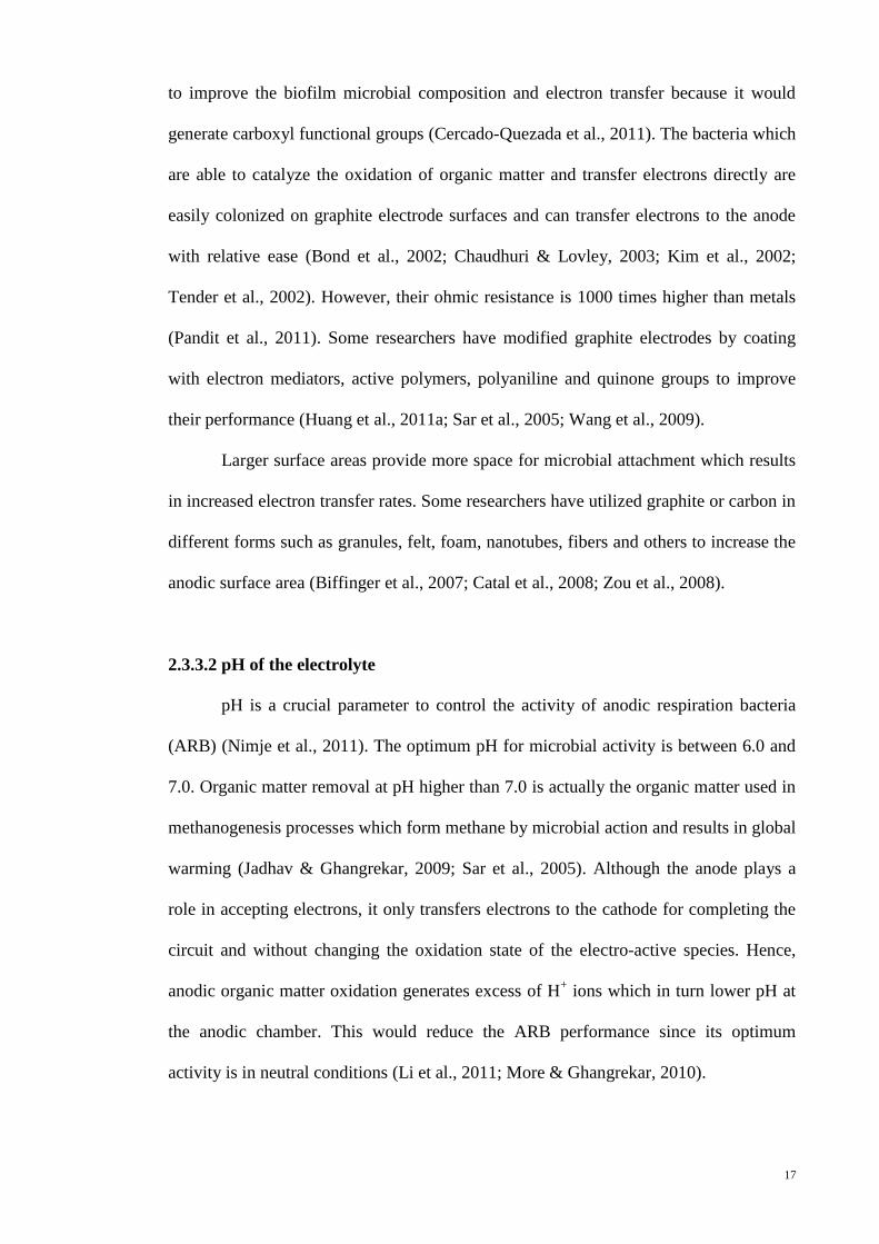
to improve the biofilm microbial composition and electron transfer because it would
generate carboxyl functional groups (Cercado-Quezada et al., 2011). The bacteria which
are able to catalyze the oxidation of organic matter and transfer electrons directly are
easily colonized on graphite electrode surfaces and can transfer electrons to the anode
with relative ease (Bond et al., 2002; Chaudhuri & Lovley, 2003; Kim et al., 2002;
Tender et al., 2002). However, their ohmic resistance is 1000 times higher than metals
(Pandit et al., 2011). Some researchers have modified graphite electrodes by coating
with electron mediators, active polymers, polyaniline and quinone groups to improve
their performance (Huang et al., 2011a; Sar et al., 2005; Wang et al., 2009).
Larger surface areas provide more space for microbial attachment which results
in increased electron transfer rates. Some researchers have utilized graphite or carbon in
different forms such as granules, felt, foam, nanotubes, fibers and others to increase the
anodic surface area (Biffinger et al., 2007; Catal et al., 2008; Zou et al., 2008).
2.3.3.2 pH of the electrolyte
pH is a crucial parameter to control the activity of anodic respiration bacteria
(ARB) (Nimje et al., 2011). The optimum pH for microbial activity is between 6.0 and
7.0. Organic matter removal at pH higher than 7.0 is actually the organic matter used in
methanogenesis processes which form methane by microbial action and results in global
warming (Jadhav & Ghangrekar, 2009; Sar et al., 2005). Although the anode plays a
role in accepting electrons, it only transfers electrons to the cathode for completing the
circuit and without changing the oxidation state of the electro-active species. Hence,
anodic organic matter oxidation generates excess of H+ ions which in turn lower pH at
the anodic chamber. This would reduce the ARB performance since its optimum
activity is in neutral conditions (Li et al., 2011; More & Ghangrekar, 2010).

18
To overcome this issue, a base buffer (normally a phosphate buffer) or carbonate
has to be added to combine with H+ and then form a weaker acid. Equation 2.1 to 2.3
indicate acid-base buffer and acid-carbonate buffer equilibrium reactions where Alk- is
alkalinity, HAlk is protonated alkalinity, are carbonate ions,
are
bicarbonate ions, H2CO3 is carbonic acid and CO2 is carbon dioxide gas (Oh et al.,
2010; Santoro et al., 2011; Tsan et al., 2011). Carbonate buffer is more beneficial than
phosphate buffer in adjusting pH since inorganic carbon is available in all natural water
(Marcus et al., 2011). Besides that, carbonate and bicarbonate can be reused in
controlling pH since carbon dioxide gas generated from acid-carbonated buffer
reactions (Eq. 2.4) is recycled internally to the cathode and then re-produce carbonate
and bicarbonate again. The carbonate and bicarbonate ions are diffused back to the
anodic chamber and the recycle process is repeated again (Tsan et al., 2011). The results
of organic matter removal had been summarized in Table 2.5.
+ H+ ↔ HAlk (2.1)
+ H
+ ↔
(2.2)
+ H
+ ↔ H2CO3 (2.3)
H2CO3 ↔ CO2 + H2O (2.4)

19
Table 2.5: A summary of results obtained by various workers in BES organic matter removal
Cell configuration Electrode material Experimental Conditions Results References
Anode Cathode
Divided electrolysis
cell with proton
exchange membrane
Graphite
granules
and
graphite rod
Graphite rod pH 7 at anodic and cathodic
compartment.
Reactor 1: 6130 mgVSS/L
Reactor 2: 4550 mgVSS/L
Reactor 3: 3360 mgVSS/L
Reactor 1
COD removed: 40±2.0 ppm/h
Ammonia removed: 1.37 ppm/h
Reactor 2
COD removed: 25±1.3 ppm/h
Ammonia removed: 0.54 ppm/h
Reactor 3
COD removed: 24±1.2 ppm/h
Ammonia removed: 0.53 ppm/h
Aboutalebi et al.,
2011
Electrolysis cell
divided with 3mm J-
cloth and either
Nafion 117
membrane presented
5mm thick
carbon felt
Gas diffusion
electrode with a
Pt load of 0.5
mg/cm2
Acetate: 4.4 gLA-1
d-1
Continuous mode
pH 7
Ww flowrate: 5 ml/d
Trace metal solution
flowrate: 146 ml/d
HRT: 24 hr
1.0 V
With Membrane
H2 production: 5.57 LSTP LA-1
d-1
Acetate removal: ~98%
Without Membrane
H2 production: 1.22 LSTP LA-1
d-1
Acetate removal: ~42%
Tartakovsky et al.,
2009

20
Table 2.5: A summary of results obtained by various workers in BES organic matter removal (Continued)
Cell configuration Electrode material Experimental Conditions Results References
Anode Cathode
Electrolysis cell
divided with 0.7 mm
polyester cloth
5mm thick
carbon felt
Carbon paper
gas diffusion
electrodeposited
with Ni
Applied voltage: 1.09-1.2V
Standard phase
OLR: 4 g LR-1
d-1
HRT: 9.5 h
Influent: 1.6 g/L
Phase 1: Varying OLR
OLR: 8 g LR-1
d-1
HRT: 9.5 h
Influent: 3.3 g/L
Phase 2: Varying HRT
OLR: 4 g LR-1
d-1
HRT: 16.5 h
Influent: 3.1 g/L
Standard phase
COD removal: 85%
H2 generated: 79%
CE: 79.1%
Phase 1
COD removal: 92.5%
H2 generated: 86%
CE: 69.8%
Phase 2
COD removal: ~100%
H2 generated: 79%
CE: 81.5%
Tartakovsky et al.,
2011
21
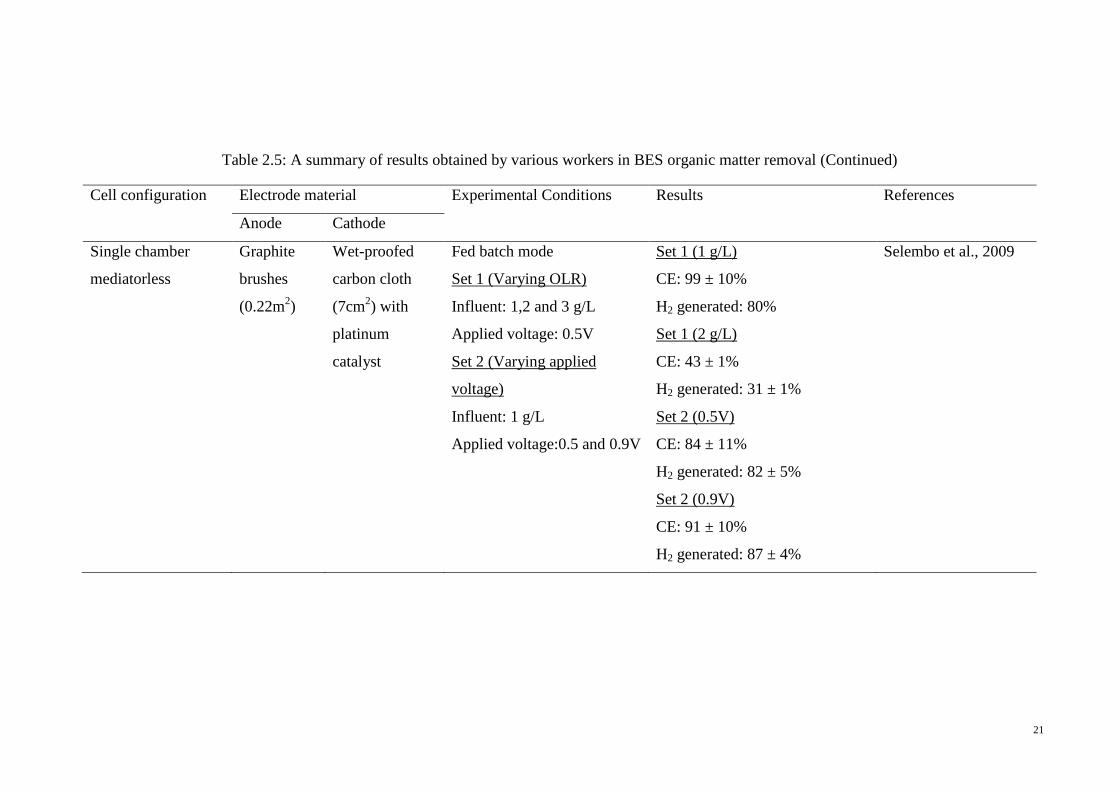
Table 2.5: A summary of results obtained by various workers in BES organic matter removal (Continued)
Cell configuration Electrode material Experimental Conditions Results References
Anode Cathode
Single chamber
mediatorless
Graphite
brushes
(0.22m2)
Wet-proofed
carbon cloth
(7cm2) with
platinum
catalyst
Fed batch mode
Set 1 (Varying OLR)
Influent: 1,2 and 3 g/L
Applied voltage: 0.5V
Set 2 (Varying applied
voltage)
Influent: 1 g/L
Applied voltage:0.5 and 0.9V
Set 1 (1 g/L)
CE: 99 ± 10%
H2 generated: 80%
Set 1 (2 g/L)
CE: 43 ± 1%
H2 generated: 31 ± 1%
Set 2 (0.5V)
CE: 84 ± 11%
H2 generated: 82 ± 5%
Set 2 (0.9V)
CE: 91 ± 10%
H2 generated: 87 ± 4%
Selembo et al., 2009
22
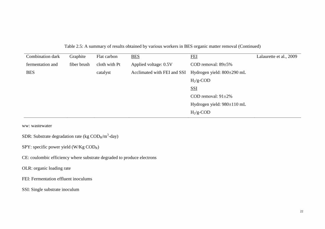
Table 2.5: A summary of results obtained by various workers in BES organic matter removal (Continued)
Combination dark
fermentation and
BES
Graphite
fiber brush
Flat carbon
cloth with Pt
catalyst
BES
Applied voltage: 0.5V
Acclimated with FEI and SSI
FEI
COD removal: 89±5%
Hydrogen yield: 800±290 mL
H2/g-COD
SSI
COD removal: 91±2%
Hydrogen yield: 980±110 mL
H2/g-COD
Lalaurette et al., 2009
ww: wastewater
SDR: Substrate degradation rate (kg CODR/m3-day)
SPY: specific power yield (W/Kg CODR)
CE: coulombic efficiency where substrate degraded to produce electrons
OLR: organic loading rate
FEI: Fermentation effluent inoculums
SSI: Single substrate inoculum

23
2.3.4 Factors controlling denitrification
Autotrophic denitrification gives more advances in removal efficiency compared
to heterotrophic denitrification since no further process required removing excess
substrate and biomass production. Hydrogen gas is generally chosen as an electron
donor source in autotrophic denitrification process since it has lower cost and does not
generate any toxic byproducts (Sunger & Bose, 2009). However, hydrogen gas has low
solubility in water and is also easier explosive (Szekeres et al., 2001; Virdis et al.,
2010). Hence, some researchers had investigated a method to immobilize denitrifying
bacteria on the cathode surface and utilized hydrogen gas produced from the electrolysis
of water (Prosnansky et al., 2002). The denitrification reactions utilize hydrogen
produced from the cathodic water electrolysis are depicted in Equation 2.5 to 2.8
(Ghafari et al., 2009b). There are general factors that affects on denitrification in BES
includes electrode material, pH and electric current.
2H2O + 2e → H2 + 2OH- (2.5)
NO3- + H2 → NO2
- + H2O (2.6)
2NO2- + 3H2 →N2 + 2H2O + 2 OH
- (2.7)
Overall reaction:
2NO3- + 5H2 → N2 + 4H2O + 2OH
- (2.8)
2.3.4.1 Cathodic material
Carbon material has sufficient mechanical strength and a rough surface which is
ideal for the formation of biofilm as compared with stainless steel (Biffinger et al.,
2007; Dumas et al., 2008). However, carbon material is difficult to apply in large scale
processes due to its brittleness, bulky nature and high electrical resistivity caused larger
electrode ohmic losses. Hence, graphite and carbon electrodes are supported by a
conductive metal current collector such as stainless steel mesh (Rozendal et al., 2008).

24
Some researchers had suggested stainless steel and platinum more suitable used as
cathodic material due to their strength, common manageability and better electrokinetic
properties to support biofilm driven reductions as compared with carbon materials (Cast
& Flora, 1998a). But, there is easier formation of a platinum oxide (PtO) layer at
platinum electrode surface which will disrupt the denitrification process (Du et al.,
2007). Graphite granules have been widely used in treating wastewater due to its large
surface area that allow more bacteria attached on it and acted as third bipolar electrode
(Zhou et al., 2009).
2.3.4.2 pH of the electrolyte
The pH of the wastewater is one of factor affect the performance of
hydrogenotrophic denitrification. Nitrite concentration is higher when the pH value is
more than 8.6 whereas when pH less than 7.0, carbonate ions are decomposed and
hence decreases the nitrate removal rate (Karanasios et al., 2010). During batch
denitrification process, pH of the solution increases and is normally adjusted between
6.5 and 7.0 by using phosphoric acid (Cast & Flora, 1998a). pH can also be adjusted by
carbon dioxide gas produced at the anode which is controlled by electric current
(Sukkasem et al., 2008). Equation 2.9 to 2.11 indicates the mechanism of adjusting pH
by carbon dioxide where carbon dioxide dissolves in water to form carbonic acid then
reacts with OH- to produce
. further reacts with OH
- to form
. This
mechanism shows that using carbon dioxide can increase electric conductivity in water
and lower ohmic potential drop since more ions ( ,
) are present in the
electrolyte (Prosnansky et al., 2002). Clauwaert and his co-workers (2009) had proved
that only 26% of nitrate had been removed without pH adjustment, whereas the nitrate
removal increased when the pH maintained at neutrality. The optimal pH for
denitrification is between 6.5 and 8.0 which agreed with few researchers.
25
CO2 + H2O → H2CO3 (2.9)
H2CO3 + OH- → H2O + H
(2.10)
H + OH
- → H2O +
(2.11)
2.3.4.3 Electric current
Electric current would influence the hydrogen formation at the cathodic
chamber, indirectly, it play a vital role in nitrate reduction since hydrogen is required
for autotrophic denitrification. Some researchers are proved that bio-cathode
denitrification is more advanced at lower electrical currents due to hydrogen is the
limiting factor in the process (Cast & Flora, 1998b; Zhang et al., 2005). When electric
current is higher, hydrogen gas production through electrolysis is increased and
effervescence can be clearly observed. The gas bubbles causes channeling in granular
activated carbon beds and forms a dry space which lowers the denitrification
performance (Szekeres et al., 2001). Besides that, higher electric current enhances the
production of oxygen at the anodic side which would compete with hydrogen
generation to lower the hydrogenotrophic denitrification reaction (Wan et al., 2009).
The applied current trend also supported by Flora et al., (1994) who concluded that
larger current density yield excessive hydrogen gas which remains in biofilm and
caused decreases denitrification rate (Flora et al., 1994).
The bio-cathode denitrification technique has been applied by many researchers
to remove nitrate and a summary of their results are presented in Table 2.6.

26
Table 2.6: A summary of results obtained by various workers in bio-cathode denitrification
Cell configuration Electrode material Experimental Conditions Results References
Anode Cathode
Anode is surrounded by
biofilm cathode and
combination with adsorption
column
Carbon (160
cm2)
251cm2 Continuous mode
HRT: 10 hr
Electric current: 5 mA
Initial nitrate: 22.5 mg/L
NO-3-N removal: 54.67%
NO-2-N: 0.01 mg/L
Feleke & Sakakibara,
2002
Divided electrolysis cell with
cationexchange membrane
Stainless steel
Stainless steel
wrapped with
stainless steel
mesh
pH 7
Electric current: 1 mA
Initial nitrate: 20 mg NO-3/L
Without heavy metal
Current efficiency: 54.3%
With heavy metal
Current efficiency: 24.3%
Cast & Flora, 1998b
Graphite
wrapped with
polypropylene
mesh
Without heavy metal
Current efficiency: 34.1%
With heavy metal
Current efficiency: 27.5%

27
Table 2.6: A summary of results obtained by various workers in bio-cathode denitrification (Continued)
Cell configuration Electrode material Experimental Conditions Results References
Anode Cathode
Anode is surrounded by
biofilm cathode
Carbon carbon Flowrate: 2.65 L/d
Recycle rate: 1.14 L/min
Initial NO3-N: 20 mg/L
Applied current: 0-100mA
pH 7.0
20mA
Nitrate removal: 98%
N2 production: 98.95%
100mA
Nitrate removal: 35%
N2 production: 69.32%
Islam & Suidan, 1998
Flowrate: 2.65 L/d
Recycle rate: 1.14 L/min
Initial NO3-N: 20 mg/L
Applied current: 25mA
Nitrate removal: 82- 87%
Divided electrolysis cell with
porous, water permeable
plastic foam
Platinum-
coated
titanium
Stainless steel
and granular
activated
carbons
Continuous mode
HRT: 0.33-6 h
Current density: 2.7-20
A/m2
Current denitrification: 30-90% Prosnansky et al., 2002

28
Table 2.6: A summary of results obtained by various workers in bio-cathode denitrification (Continued)
Cell configuration Electrode material Experimental Conditions Results References
Anode Cathode
Divided electrolysis cell with
cationexchange membrane
Dimensionally
stable anode
(DSA)
Graphite felt 300C
Applied current: 200 mA
pH: 7.0
Nitrate removal: 98% Park et al., 2005
Divided electrolysis cell with
cationexchange membrane
and graphite granules
n/a n/a pH 7.2
Current density: 23.4
mA/cm2
Flowrate: 0.35 L/h
Nitrate removal: 74% Clauwaert. et al., 2009
Divided electrolysis cell with
porous sponge foam rubber
Pt- coated
metal
Titanium Current density: 0.82
mA/cm2
HRT: 6 h
pH: 6-7
Current efficiency: ~70% Sakakibara &
Nakayama, 2001

29
Table 2.6: A summary of results obtained by various workers in bio-cathode denitrification (Continued)
Cell configuration Electrode material Experimental Conditions Results References
Anode Cathode
Divided electrolysis cell with
cationexchange membrane
Titanium plate
coated with
platinum-
iridium oxide
(2mm thick)
Graphite plate
(5mm thick)
Continuous mode
25-270C
Water velocity: 0.11 m/h
Initial NO3-N: 21-27
mg/L
Applied current: 40-
100mA
40 mA
Nitrate removal: ~26%
Nitrite generated: ~3.5mg/L
50 mA
Nitrate removal: ~29%
Nitrite generated: ~2mg/L
60 mA
Nitrate removal: ~48%
Nitrite generated: ~0.2mg/L
70 mA
Nitrate removal: ~81%
Nitrite generated: ~0.2mg/L
80 mA
Nitrate removal: ~78%
Nitrite generated: ~3.5mg/L
90 mA
Nitrate removal: ~75%
Nitrite generated: ~3.0 mg/L
Szekeres et al., 2001

30
CHAPTER 3: MATERIALS AND METHODS
Before starting the experiments, palm shell granular activated carbon (GAC),
carbon and graphite felt have to be washed by synthetic wastewater to eliminate the
adsorption effect. Denitrifying bacteria from brewery factory was acclimated and
immobilized on the GAC surface. Then, electric current was applied to allow the
bacteria adapted with the system. For comparison of anode materials, the electrode
spacing, electric current and HRT were set at 3 cm, 10 mA and 6 hours. The screening
ranges for the three parameters were fixed at 0.2 to 5.5 cm, 0 to 25 mA and 3 to 60
hours, respectively. Response surface methodology (RSM) would be used after
obtaining the suitable parameters range.
3.1 Preparation of electrodes
Palm shell granular activated carbon (GAC) having a porosity of 66.5% was
applied as the cathodic material and support for auto hydrogenotrophic biofilm (GAC
was found from Bravo Green Sdn. Bhd., Sarawak, Malaysia). The GAC was sieved to a
size ranging from 1.4 to 2.0 mm. Prior to its application, it was washed with 0.02 M
sulphuric acid (H2SO4) and deionized water several times to eliminate dust and
contaminants and then dried in an oven at 1050C for 24 hours in order to eliminate
surface moisture. To eliminate adsorption effect of GAC, it was washed by synthetic
wastewater.
Titanium (porosity was not measured), stainless steel mesh (hole size 2mm x
2mm), nano-crystalline lead (IV) oxide (PbO2), carbon felt and graphite felt (both felts
had a porosity of 0.95) were applied as anode materials. Each electrode possessed an
area of 25cm2 (5 cm × 5 cm). Titanium was purchased from Sigma-Aldrich where as
carbon and graphite felts were provided by SGL Carbon Ltd and stainless steel mesh
was delivered by Power Hardware & Trading. Titanium and stainless steel mesh were

31
polished by means of fine grade (P100) sand paper to eliminate the pollutions and the
saturated with 0.02 M H2SO4 and rinsed with deionized water. Same pre-dealing phase
was faced by carbon and graphite felts but the polishing step was excluded. Moreover,
they have faced similar saturation treatment as the GAC had received.
The nano-crystalline PbO2 were prepared in University of Southampton and the
preparation procedure as documented in the literatures (Sirés et al., 2008; Sirés et al.,
2010). In brief, a galvanostatic method was used to deposit PbO2 coatings on various
carbon/polyvinyl-ester composite substrates in aqueous methane sulphonic acid
electrolytes. A small, cylindrical, undivided cell containing 80cm3 of solution was
applied effectively to serve the purpose. The cell was magnetically stirred at 300 rpm
with a PTFE-coated cylindrical stirring bar (4.5 cm length × 0.8 cm diameter) to ensure
reproducible mass transport conditions. The mean thickness of the PbO2 coatings was
1.9 and 18 μm at 5 and 50 mA cm−2
, respectively (these were the only current densities
used during the course of the preparation process) (Sirés et al., 2010).
3.2 Reactor configuration
The reactor was constructed from Plexiglas, having 9.5 cm inner diameter and
30cm height as demonstrated in Figure 3.1. Stainless steel rods 5 cm in height were
screwed on to an aluminum plate which was installed at the bottom of the reactor to
provide better electrical distribution to the GAC. The anode was hung in the reactor by
fitting it to four stainless steel support rods. The top and bottom stainless steel rods in
the reactor were connected to a programmable direct current (DC) power supply (RS
Components, England). The GAC was then immersed in a 2% agar solution at a boiling
temperature and left to cool before being installed into the reactor to deliver an adhesive
surface on the GAC for accelerating the growth of the autohydrogenotrophic biofilm.
32
The cathodic bed was created with a height of 8 cm with GAC from the bottom of the
reactor.
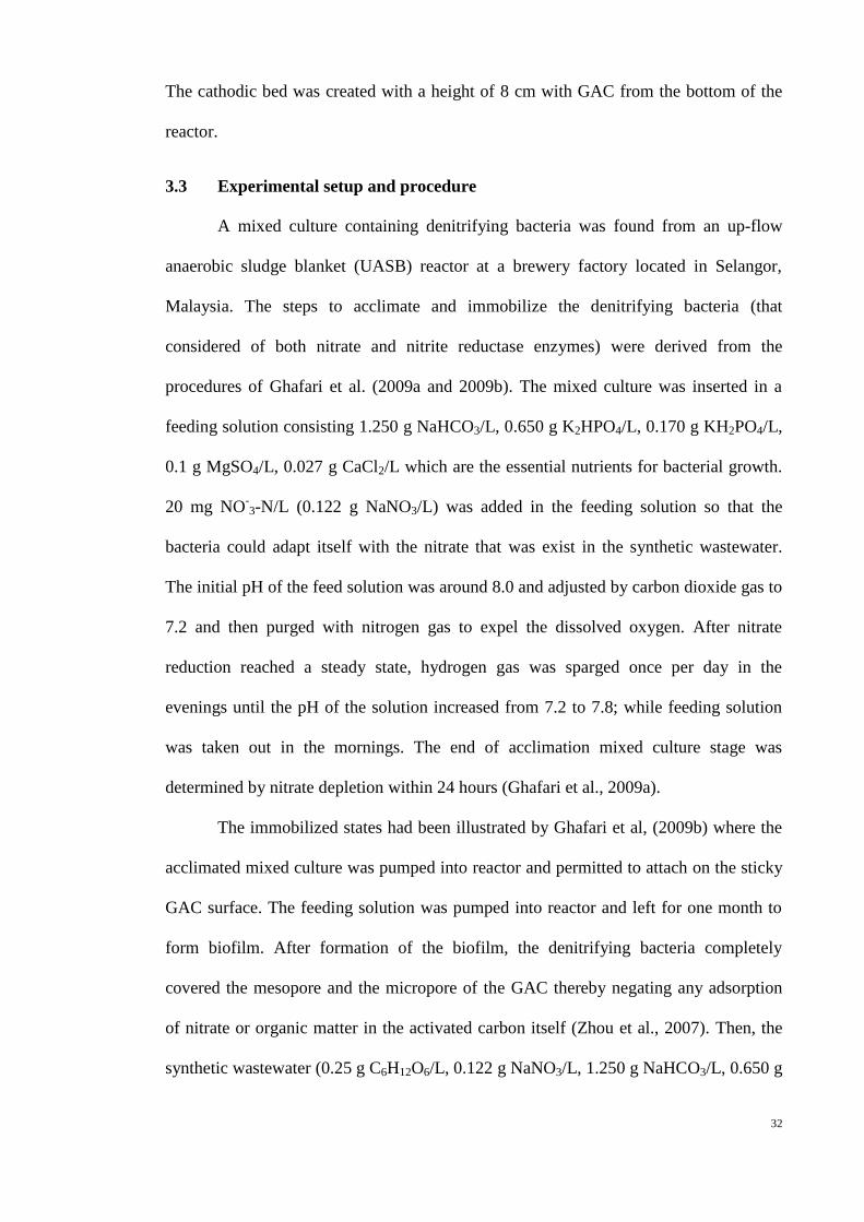
3.3 Experimental setup and procedure
A mixed culture containing denitrifying bacteria was found from an up-flow
anaerobic sludge blanket (UASB) reactor at a brewery factory located in Selangor,
Malaysia. The steps to acclimate and immobilize the denitrifying bacteria (that
considered of both nitrate and nitrite reductase enzymes) were derived from the
procedures of Ghafari et al. (2009a and 2009b). The mixed culture was inserted in a
feeding solution consisting 1.250 g NaHCO3/L, 0.650 g K2HPO4/L, 0.170 g KH2PO4/L,
0.1 g MgSO4/L, 0.027 g CaCl2/L which are the essential nutrients for bacterial growth.
20 mg NO-3-N/L (0.122 g NaNO3/L) was added in the feeding solution so that the
bacteria could adapt itself with the nitrate that was exist in the synthetic wastewater.
The initial pH of the feed solution was around 8.0 and adjusted by carbon dioxide gas to
7.2 and then purged with nitrogen gas to expel the dissolved oxygen. After nitrate
reduction reached a steady state, hydrogen gas was sparged once per day in the
evenings until the pH of the solution increased from 7.2 to 7.8; while feeding solution
was taken out in the mornings. The end of acclimation mixed culture stage was
determined by nitrate depletion within 24 hours (Ghafari et al., 2009a).
The immobilized states had been illustrated by Ghafari et al, (2009b) where the
acclimated mixed culture was pumped into reactor and permitted to attach on the sticky
GAC surface. The feeding solution was pumped into reactor and left for one month to
form biofilm. After formation of the biofilm, the denitrifying bacteria completely
covered the mesopore and the micropore of the GAC thereby negating any adsorption
of nitrate or organic matter in the activated carbon itself (Zhou et al., 2007). Then, the
synthetic wastewater (0.25 g C6H12O6/L, 0.122 g NaNO3/L, 1.250 g NaHCO3/L, 0.650 g

33
K2HPO4/L, 0.170 g KH2PO4/L, 0.1 g MgSO4/L, 0.027 g CaCl2/L) was pumped
continuously at an HRT of 24 hours for 10 days (after formation of the biofilm) while
no electricity was employed in the reactor to allow the mixed culture for adapting with
the synthetic wastewater. Before commencement of experiments, synthetic wastewater
at neutral pH (without being sparged with hydrogen) was delivered continuously in 3
days at an electric current of 10 mA that was optimum current for denitrifying bacteria
survival (Ghafari et al., 2009b; Ghafari et al., 2010).
As shown in Figure 3.1, the synthetic wastewater was kept in a 2 L storage tank
and sparged with pure nitrogen gas for 15 minutes to exclude oxygen in the solution
since the denitrification process more effectively under anaerobic circumstances (Krul,
1976). Then, the pH of synthetic wastewater was adjusted to 7.2 using carbon dioxide
gas before being pumped into the reactor.
Figure 3.1: Schematic representation of the experimental set-up
3.4 Comparison of anode materials
All the anode materials were hung with four stainless steel support rods and the
electrodes spacing, electric current and HRT were set at 3 cm, 10 mA and 6 hours.
Before initiate with a new experiment, the solution inside the reactor was purged with
pure nitrogen gas for 15 minutes before discharged it out. This is only to ensure that no
Power supply
Anode
Cathode
(GAC bed)
Discharge point
Sampling
Inlet
Pump
Magnetic stirrer
Synthetic wastewater
storage tank

34
oxygen gas was trapped inside the reactor that generated from previous experiment. 5
ml of samples were taken and used to analysis.
3.5 Screening of parameters range
3.5.1 Screening of electrodes spacing range
After picking up the appropriate anode electrodes from section 3.4, the electrodes
spacing was varied between 0.2 cm and 5.5 cm to found the perfect range to use in next
objective. The electric current and HRT were set at 10 mA and 6 hours.
3.5.2 Screening of electric current range
To observe the electric current range, the electrodes spacing and HRT were installed at
constant value that were 3 cm and 6 hours, respectively. For electric current was set at 0
mA, 5 mA, 10 mA, 20 mA and 25 mA.
3.5.3 Screening of HRT range
The HRT range that selected was from 3 hours to 60 hours; while the electrodes spacing
and electric current were at 3 cm and 10 mA, respectively. All the organic matter and
nitrate-nitrogen elimination in screening phase was estimated by applying the equation
3.1 and 3.2.
3.6 Analytical methods
Nitrate and nitrite concentration were determined by HPLC (Shimadzu 10A)
using a UV detector at 210 nm. A Phenomenex Hypersil column (Thermo Electron
Corporation, USA) with an internal diameter of 150 mm × 4.6 mm was packed with 5
µm particles for analytical purposes. Organic compound was analyzed by chemical
oxygen demand (COD) method (HACH DRB 200) that is the indirect measurement of
the amount of organic compound in water (APHA, 1999). The GAC, titanium and PbO2
anode surfaces were scanned by means of FESEM (AURIGA, ZEISS) under high

35
vacuum conditions at an accelerating voltage of 1 kV; graphite and carbon felt surfaces
were scanned by means of optical microscopy (DMLS, Leica, Germany) and the image
was captured with a camera (DFC 290, Leica, Germany).
Performances of bio-electrochemical reactor can be expressed by means of
organic matter, nitrate-nitrogen elimination, current efficiency (CE) and specific
denitrification (SD) which is defined as follows (Zhou et al., 2009; Islam and Suidan,
1998):
Organic matter removal = CO i CO f
CO i 100 (3.1)
Nitrate-nitrogen removal =
–
100 (3.2)
[ ]
(3.3)
where CODi and CODf are initial and final COD value (mg/L), and
demonstrate initial and final nitrate-nitrogen concentration (mg/L), Xin and Xeff are
influent and effluent concentration of nitrate-nitrogen (mg/L), Yeff is the effluent
concentration of nitrite-nitrogen (mg/L), I is the current supplied (mA), F refer to the
Faraday’s constant (96485 C/mol) and Q is the electrolyte flowrate (mL/h), U is the
voltage (V), 5 and 3 are the stoichiometric coefficient for nitrate and nitrite and 14 is
nitrogen equivalent mass (mg eq-1
).
3.7 Experimental design
The three most significant process parameters are electrode spacing, electric
current and HRT and these are demonstrated as X1, X2 and X3, correspondently. The
statistical design and data analysis were carried out by Design-Expert Software (version

36
8.0.7.1). The central composite design (CCD) method was selected to decrease the
number of tests and optimize the effective process variables. The number of
experiments designed by CCD at five levels was 17 runs including 3 repeated
experimental runs at the central point to eliminate errors and curvature.
The three response functions (nitrate-nitrogen and organic matter removal
percentage, nitrite nitrogen concentration) were predicted and expressed follows a
quadratic equation as given by Equation (3.5).
∑
∑
∑∑
Where Y is the predicted response, i is the linear coefficient, j is the quadratic
coefficient, β is the regression coefficient, k is the number of factors studied and
optimized in the experiment and e is the random error. The statistical analysis and
adequacy test was carried out by analysis of variance (ANOVA). The statistical
significance was tested by the F-test in the same program and the approvable model
terms were based on a probability value with 95% confidence level.

37
CHAPTER 4: RESULTS AND DISCUSSIONS
4.1 Comparison of anode material on organic matter and nitrate removal
Titanium, stainless steel, lead (IV) oxide, graphite and carbon felt are the
common electrode materials due to its cheap and availability. Titanium and stainless
steel mesh showed the worst performance amongst all the tested anodes; merely 9% and
13% of COD was removed at the end of the process (Figure 4.1). This is because both
materials were ‘active’ electrodes due to which there is a strong interaction between
electrode and hydroxyl radicals (.OH), causing oxygen transfer from the hydroxyl
radicals to the anode surface resulting in the formation of other compounds rather than
organic matter oxidation (Alfaro et al., 2006). This result was similar with that reported
by Cañizares et al, (2002) who observed the difference of active (stainless steel thin
film) and non-active electrode (diamond thin film) in oxidation of aqueous acid
phenolic waste. They found that ‘non-active’ electrode was more advanced since it
caused a weak interaction between the electrode and hydroxyl radicals, so the radicals
could rapidly react with the waste. Thus the ‘active electrode’ surface would combine
with the radicals to form other higher molecular weight compounds.
The COD elimination of applying titanium was inferior than that for stainless
steel mesh since titanium’s standard electrode potential (V versus SHE) was lower than
that of stainless steel (stainless steel being an alloy of iron, chromium and nickel). Thus,
stainless steel mesh could oxidize better than titanium. Moreover, Feng et al, (2003) had
proved that no hydroxyl radicals were detected on titanium surfaces by analyzing with
p-nitrosodimethylaniline (RNO). This could be because titanium had a propensity to
generate oxygen from the electrolysis of water, thereby negating the chances of
hydroxyl radical formation. Moreover, the physical characteristics of titanium was not
similar with others applied in this work since titanium was a solid electrode while other

38
anodes were porous or mesh like in nature (Figure 4.2 a-d). The porous and mesh
structure could provide a large active surface area and could boost the formation of
hydroxyl radicals (.OH).
Nano-crystalline PbO2, carbon and graphite felt are ‘non-active’ electrodes, but
PbO2 had the highest oxidation power and was able to generate reactive hydroxyl
radicals {PbO2(.OH) } (Eq. 4.1 and 4.2) that result the overall organic matter oxidation
(Sirés et al., 2008; Sirés et al., 2010).
PbO2 + H2O →PbO2(.OH) + H
+ + e
- (4.1)
Organic matter + PbO2(.OH) → CO2 + PbO2+ zH
+ + ze
- (4.2)
The nitrate-nitrogen removal is highly dependent on the pH of the process. As
described in Eq. 2.8, the pH of the system tends to increase as hydroxyl ions are
generated and higher pH has a common propensity to retard the denitrification process.
The carbon dioxide produced from the anodic oxidation of organic compounds would
transfer to the cathodic part and adjust the pH by dissolving the carbon dioxide into
water to form as the final product (as depicted in Eq. 4.3-4.5) (Freguia et al,
2008). However, the electrolytic ohmic loss in transferring carbon dioxide between
anodic and cathodic sides has to be minimized by decreasing the migration distance
(Rozendal et al., 2008).
CO2 + H2O → H2CO3 (4.3)
H2CO3 + OH- → H2O + H
(4.4)
H + OH
- → H2O +
(4.5)
In comparison to the different anodes studied in this work, PbO2 demonstrated
the highest removal of organic matter and nitrate-nitrogen. This was in accordance with
the literature (Sirés et al., 2010; Flox et al., 2009; Zhou et al., 2011). The other part of

39
this research involved investigating parameters range and the usage of response surface
methodology to determine optimum reactor conditions for simultaneous removal of
both organic matter and nitrate.
Figure 4.1: Organic compounds and nitrate-nitrogen removal with different types of
anode material.
0
10
20
30
40
50
60
70
80
90
100
Titanium Stainless steel
mesh
Lead (IV)
oxide
Graphite felt Carbon felt
Rem
oval
eff
icie
ncy
, %
Anode material
Organic matter Nitrate-nitrogen
Initial nitrate nitrogen = 20 mg L-1
.
Initial COD = 247 mg L-1
.

40
Figure 4.2 (a) FESEM image of titanium (10,000 x). (b) FESEM image of lead (IV)
oxide (10,000 x). (c) Microscope image of graphite felt (100 x). (d) Microscope image
of carbon felt (100 x). (e) FESEM image of GAC (10,000 x). (f) FESEM image of GAC
(100,000 x)
3 μm 3 nm
(a) (b)
(c) (d)
(e) (f)
41
4.2 Screening of different parameters range
4.2.1 Screening of electrodes spacing range
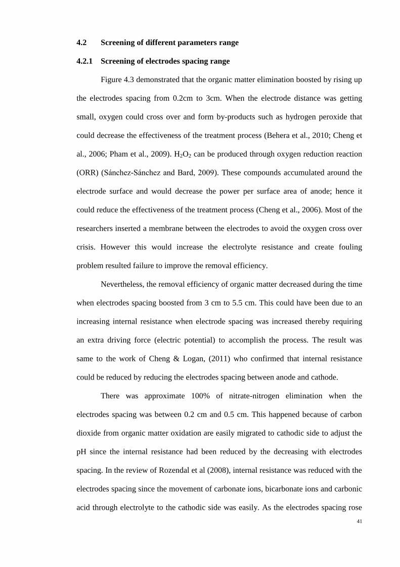
Figure 4.3 demonstrated that the organic matter elimination boosted by rising up
the electrodes spacing from 0.2cm to 3cm. When the electrode distance was getting
small, oxygen could cross over and form by-products such as hydrogen peroxide that
could decrease the effectiveness of the treatment process (Behera et al., 2010; Cheng et
al., 2006; Pham et al., 2009). H2O2 can be produced through oxygen reduction reaction
(ORR) (S nchez-S nchez and ard, 2009). These compounds accumulated around the
electrode surface and would decrease the power per surface area of anode; hence it
could reduce the effectiveness of the treatment process (Cheng et al., 2006). Most of the
researchers inserted a membrane between the electrodes to avoid the oxygen cross over
crisis. However this would increase the electrolyte resistance and create fouling
problem resulted failure to improve the removal efficiency.
Nevertheless, the removal efficiency of organic matter decreased during the time
when electrodes spacing boosted from 3 cm to 5.5 cm. This could have been due to an
increasing internal resistance when electrode spacing was increased thereby requiring
an extra driving force (electric potential) to accomplish the process. The result was
same to the work of Cheng & Logan, (2011) who confirmed that internal resistance
could be reduced by reducing the electrodes spacing between anode and cathode.
There was approximate 100% of nitrate-nitrogen elimination when the
electrodes spacing was between 0.2 cm and 0.5 cm. This happened because of carbon
dioxide from organic matter oxidation are easily migrated to cathodic side to adjust the
pH since the internal resistance had been reduced by the decreasing with electrodes
spacing. In the review of Rozendal et al (2008), internal resistance was reduced with the
electrodes spacing since the movement of carbonate ions, bicarbonate ions and carbonic
acid through electrolyte to the cathodic side was easily. As the electrodes spacing rose

42
from 0.5 cm to 5.5 cm, the nitrate-nitrogen removal efficiency was reduced from 99%
to 84%. This could be explained by internal resistance factor as well where it increased
when the distance between anode and cathode became far apart. Despite carbon dioxide
produced higher in 3cm electrodes spacing, carbonate and bicarbonate ions would react
with H+ in the electrolyte (Eq. 4.6 and 4.7) rather than transfer to the cathodic side to
react with hydroxyl ions since internal resistance is higher.
+ H
+ ↔
(4.6)
+ H
+ ↔ H2CO3 (4.7)
From the outcome found, the appropriate range of electrodes spacing for
response surface methodology (RSM) was between 0.5 cm and 5.5 cm. The organic
matter and nitrate-nitrogen elimination efficiency only deviated around 2% between 0.2
cm and 0.5 cm, so 0.2 cm electrodes spacing could be removed. By comparing 0.5 cm
to 3 cm and 3 cm to 5.5 cm, nitrate-nitrogen elimination was poorer at 3 cm to 5.5 cm
and might be become unchangeable after 5.5 cm. Thus, the maximum electrode spacing
was 5.5 cm as during the time of the range when it is too wide would impact the action
of RSM.
Figure 4.3: Organic matter and nitrate-nitrogen removal efficiency at different
electrodes spacing.
0
20
40
60
80
100
0 0.5 1 1.5 2 2.5 3 3.5 4 4.5 5 5.5 6
Rem
oval
eff
icie
ncy
, %
Electrodes spacing, cm
Organic matter
Nitrate-nitrogen

43
4.2.2 Screening of electric current range
The plot in Figure 4.4 depicted that with the rise of applied current more organic
matter were eliminated. The rise in current promoted the generation of hydroxyl
radicals that mineralized the organic matter as limned in Eq. 4.1 and 4.2.
Notwithstanding, the elimination of organic compounds was observed to decrease at an
electric current beyond 10mA. This could be as a result of very high electric currents
could enhance the anodic water oxidation process to generate oxygen instead of
hydroxyl radical; hence oxidation of organic matters was negatively impacted. This
outcome was akin to Zhou et al. (2009) who using bio-electrochemical reactor to deal
with groundwater pollutant. They found that the highest total of carbon removal was at
23 mA and afterward no reduction because oxygen formed on the anode after the
optimum electric current value.
The nitrate-nitrogen elimination tends to be same to organic matter removal plot.
When electric current was increased, the nitrate-nitrogen elimination also improves
potentially, but at higher electric currents the elimination figures are retarded. This
could be because when applied current is swelled, water electrolysis occurs resulting in
the generation of sufficient hydrogen to increase the removal rate of nitrate. In
additional, more carbon dioxide could be generated at higher electric current on anodic
side to adjust the pH of the system. However, after 10 mA, nitrate-nitrogen removal was
reduced significantly since excessive hydrogen concentration caused channeling in
GAC beds and forms dry spaces which inhibit the denitrification performance (Szekeres
et al., 2001). Moreover, high electric current also generates higher hydroxyl ions
through the hydrolysis of water at the cathode thereby shifting the pH of the system
towards the alkaline region. This has a negative impact on the nitrate-nitrogen removal
rate (Zhou et al., 2007).

44
Since organic matter and nitrate-nitrogen elimination not attained constant at
any electric current value, the selection of maximum current value should depend on the
removal efficiency that decreases continuously for obtaining a dome shape in RSM.
Dome shape limns the removal efficiency will rise to a maximum value then reduces
afterward. By comparing 10 mA to 20 mA and 20mA to 25 mA, the eliminations trend
for both contaminants were reduced continuously but later part could be removed as
wider range would affect the precision to obtain the optimum value through RSM.
Figure 4.4: Organic matter and nitrate-nitrogen removal efficiency at different electric
current
4.2.3 Screening of HRT range
The lowest organic matter and nitrate-nitrogen elimination was at HRT 3 hours
because HRT was inversely proportional to the flow rate as showed in equation 4.8. The
flow rate was reduced thereby decreasing the organic compound loading. So, there was
sufficient reaction time for the hydroxyl radicals with organic matter.
( )
0
10
20
30
40
50
60
70
80
90
100
0 5 10 15 20 25 30
Rem
oval
eff
icie
ncy
, %
Electric current, mA
Organic matter
Nitrate-nitrogen

45
At low HRT, both contaminants did not have sufficient treatment time to treat
vast quantity pollutants before discharged to the effluent. So, the removal efficiency for
organic matter and nitrate-nitrogen was merely 43% and 24%, respectively. As HRT
rose, the both removal efficiency were increased respectively since the flowrate was
decreased and they had enough reaction time before being out to the ecosystem. After
48 hours, both contaminants removal efficiency was became constant. This could be
described by they had successfully attained equilibrate with required reaction time. The
result tend to be same to the research of Ghafari et al. (2009a) and Zhou et al. (2009a)
who proved that low HRT was failure to treat nitrate-nitrogen and total organic carbon
because of the higher loading rate. The selection of optimum HRT is also based on
some core parameters such as wastewater compositions, reactor configuration, quantity
of bacteria involved, electric current applied and electrodes spacing.
The removal efficiency of organic matter and nitrate-nitrogen in 3 to 6 hours is
diverse around 18% and 70%, respectively. Thus, it was presumed that the removal
efficiency for both contaminants reduced incessantly from 0 to 3 hours. Consequently, 0
to 3 hours was taken as the range of RSM for attaining a dome shape. The organic
matter and nitrate-nitrogen removal efficiency between HRT 48 and 60 hours only
deviated 0.4 %, so the HRT after 48 hours could be eliminated. Thus, the appropriate
range for HRT used in RSM was 0 to 48 hours.

46
Figure 4.5: Organic matter and nitrate-nitrogen removal efficiency at different HRT
4.3 Modeling and optimization using response surface methodology (RSM)
4.3.1 Development of regression equations and statistical analysis
The objective of this part was to generate a model by using RSM and observe the
interaction between parameters by applying the screening range which found in section
4.2. The correlations between the process variables and elimination of organic matter,
nitrate-nitrogen and nitrite-nitrogen accumulation were tested using central composite
design (CCD). The coded values for these variables were set at 5 levels (-1 (minimum),
-0.5, 0 (central), +0.5 and 1 (maximum)). The minimum code (-1) for HRT showing a
value of zero hours was impossible, so it was replaced by the code of -0.75 (6 h) since it
is the intermediate code between -1 and -0.5. The analysis suggested a quadratic model
for organic matter and nitrate-nitrogen elimination and a 2FI model for nitrite-nitrogen
concentration. Table 4.1 demonstrated the design of experiment as well as the
experimental results. The final regression model equation in terms of coded and actual
factors after removing the non-significant terms for three responses are depicted in
Table 4.2.
0
20
40
60
80
100
120
0 10 20 30 40 50 60 70
Rem
oval
eff
icie
ncy
, %
HRT, h
Organic matter
Nitrate-nitrogen
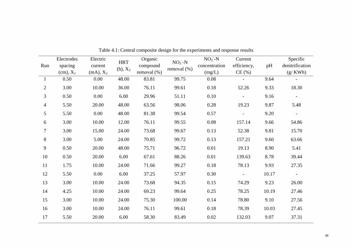
48
Table 4.1: Central composite design for the experiments and response results
Run
Electrodes
spacing
(cm), X1
Electric
current
(mA), X2
HRT
(h), X3
Organic
compound
removal (%)
NO3--N
removal (%)
NO2--N
concentration
(mg/L)
Current
efficiency,
CE (%)
pH
Specific
denitrification
(g/ KWh)
1 0.50 0.00 48.00 83.81 99.75 0.08 - 9.64 -
2 3.00 10.00 36.00 76.11 99.61 0.18 52.26 9.33 18.30
3 0.50 0.00 6.00 29.96 51.11 0.10 - 9.16 -
4 5.50 20.00 48.00 63.56 98.06 0.28 19.23 9.87 5.48
5 5.50 0.00 48.00 81.38 99.54 0.57 - 9.20 -
6 3.00 10.00 12.00 76.11 99.55 0.08 157.14 9.66 54.86
7 3.00 15.00 24.00 73.68 99.67 0.13 52.38 9.81 15.70
8 3.00 5.00 24.00 70.85 99.72 0.13 157.21 9.60 63.66
9 0.50 20.00 48.00 75.71 96.72 0.01 19.13 8.90 5.41
10 0.50 20.00 6.00 67.61 88.26 0.01 139.63 8.78 39.44
11 1.75 10.00 24.00 71.66 99.27 0.18 78.13 9.93 27.35
12 5.50 0.00 6.00 37.25 57.97 0.30 - 10.17 -
13 3.00 10.00 24.00 73.68 94.35 0.15 74.29 9.23 26.00
14 4.25 10.00 24.00 69.23 99.64 0.25 78.25 10.19 27.46
15 3.00 10.00 24.00 75.30 100.00 0.14 78.80 9.10 27.56
16 3.00 10.00 24.00 76.11 99.61 0.18 78.39 10.03 27.45
17 5.50 20.00 6.00 58.30 83.49 0.02 132.03 9.07 37.31

49
Table 4.2: Regression models
Source Models in terms of coded (Ycod) and actual (Yact)
OM Ycod = 74.14 – 2.10X1 + 5.44X2 + 10.76X3 - 3.29X1X2 - 12.06X2X3 - 16.93X12
- 9.64X22
+ 17.04X32
Yact = 27.46696 + 16.72839X1 + 4.07335X2 – 0.46937X3 – 0.13158X1X2 –
0.050255X2X3 – 2.70848X12 – 0.096406X2
2 + 0.029589X3
2
NO3--N Ycod = 99.76 + 0.40X1 + 7.96X2 + 14.92X3 - 9.52X2X3 - 17.00X2
2
Yact = 49.88051 + 0.16054X1 + 5.14745X2 + 1.01828X3 - 0.039650X2X3 - 0.17000X22
NO2--N Ycod = 0.16 + 0.11X1 - 0.085X2 + 0.075X3 - 0.052X1X2 + 0.078X1X3
Yact = 0.071503 + 0.033234X1 - (2.34415E-3)X2 - (7.75279E-4)X3 - (2.06712E-3)X1X2
+ (1.29571E-3)X1X3
X1 is electrodes spacing, X2 is electric current and X3 represent HRT
ANOVA is utilized to check the significance and adequacy of the model. The
results of the ANOVA for the three systems are described in Table 4.3. The F-value of
the model for three systems was significant and these had a 0.01 chance that a “Model
F-Value” this large could occur due to noise. Generally, values of Prob. > F being less
than 0.05 would be classified as significant effect. It was obtained that for F values
greater than 0.10 the model terms were not significant. The “F-value of Lack of Fit” for
models was 11.55, 2.61 and 3.98 implying that the lack of fits was not significant
relative to the pure error. Non-significant lack of fit was desirable and depicted that the
model was suitable to the predicted response variables within the range of parameters
studied.
The quality of the model was evaluated based on the correlation coefficient
value. The predicted R2 and adjusted R
2, tow quality measurement of the models
prediction of the response value and the amount of variation about the mean as
described by the model, respectively were assessed. From the literature, the predicted
and adjusted R2 should be within approximately 0.20 of each other to be in reasonable

50
agreement. If they are out range, there may be a trouble with either the data or the
model (Nosrati et al., 2011). In all the cases under observation, the predicted R2 and
adjusted R2
were in reasonable agreement. Based on the presented ANOVA test results,
the model usage described the simultaneous bio-electrochemical denitrification and
organic matter removal quite well and can be applied potentially to navigate the design
space.
Table 4.3: ANOVA and R-squared (R2) statistics for fitted model
F P LOF F LOF P R2 Adj. R
2 Pred. R
2 AP
OM 29.56 <0.0001 11.55 0.0818 0.9673 0.9345 0.7674 18.752
NO3--N 28.67 <0.0001 2.61 0.3075 0.9287 0.8963 0.8408 17.917
NO2--N 39.38 <0.0001 3.98 0.2169 0.9471 0.9230 0.9261 24.456
OM: Organic matter; F: F-value; P: Probability of error; LOF: Lack of fit; AP: Adequate
precision.
4.3.2 Effect of parameters on organic matter and nitrate-nitrogen removal
RSM was applied to observe the connection of three variables on organic matter
and nitrate-nitrogen elimination and accumulation of nitrite-nitrogen. Three-
dimensional plots were produced depend on the regression model in Table 4.2. Figure
4.6, 4.7 and 4.8 explained the response surface plot for organic matter and nitrate-
nitrogen removal and nitrite-nitrogen concentration upon completion of experiments.
The response surface plot in Figure 4.6(i) meant that the joint impact of
electrodes spacing and electric current on organic matter removal efficiency at constant
HRT 24 hours. The increasing of electrodes spacing and electric current would improve
the organic matter elimination. However, when electrodes spacing and electric current
were too high, it would reduce the removal efficiency since higher internal resistance
was produced and competitive electric current utilized to form oxygen and hydroxyl
radical. The effect of electric current and HRT on organic matter concentration at

51
constant electrodes spacing (3 cm) was indicated in Figure 4.6(ii). Low HRT and
electric current could not eliminate organic matter vastly for the inadequate reaction
time and lack of enough quantities of hydroxyl radicals. However, at higher HRT and
electric current, oxygen was formed prior to hydroxyl radicals even though there was
enough reaction time. Moreover, longer HRT meant higher cost due to lower specific
denitrification (Table 4.1) as electric current had to be maintained for a longer time.
Hence, HRT was found to be most important parameter compared with other variables.
Figure 4.6: Response surface plot for organic matter removal (i) interaction between
electrodes spacing and electric current. (ii) interaction between electric current and
HRT.
( i )
( ii )
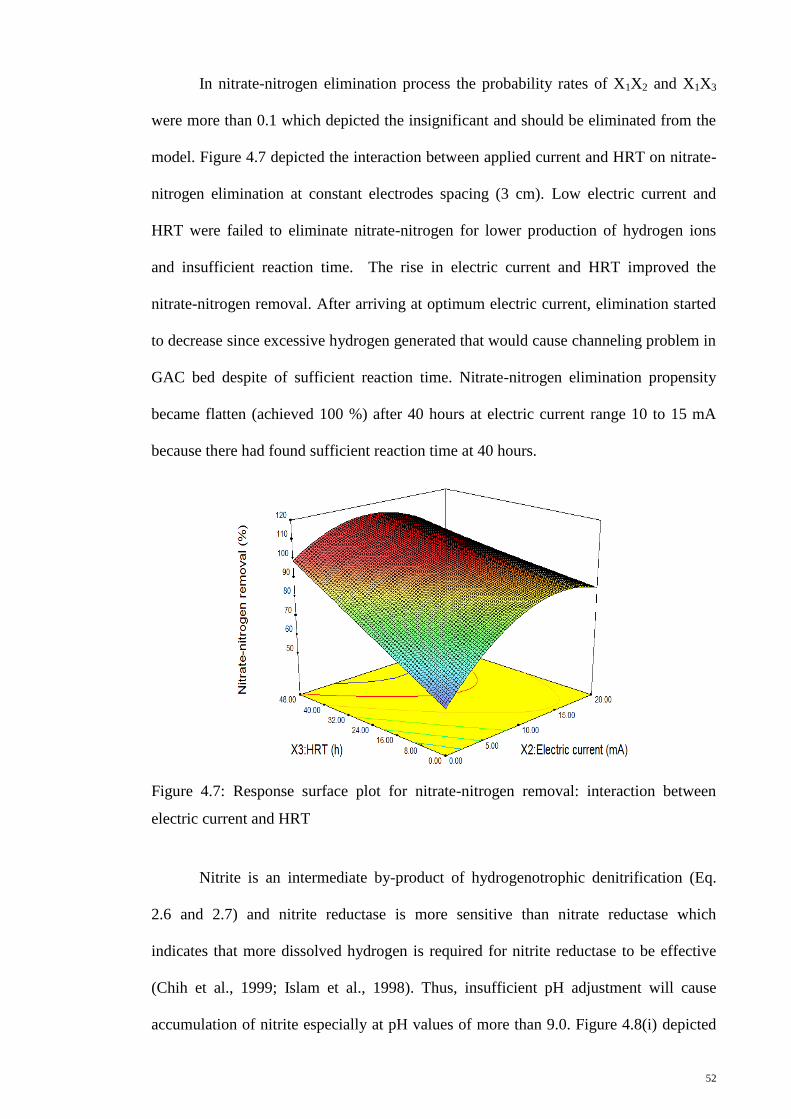
52
In nitrate-nitrogen elimination process the probability rates of X1X2 and X1X3
were more than 0.1 which depicted the insignificant and should be eliminated from the
model. Figure 4.7 depicted the interaction between applied current and HRT on nitrate-
nitrogen elimination at constant electrodes spacing (3 cm). Low electric current and
HRT were failed to eliminate nitrate-nitrogen for lower production of hydrogen ions
and insufficient reaction time. The rise in electric current and HRT improved the
nitrate-nitrogen removal. After arriving at optimum electric current, elimination started
to decrease since excessive hydrogen generated that would cause channeling problem in
GAC bed despite of sufficient reaction time. Nitrate-nitrogen elimination propensity
became flatten (achieved 100 %) after 40 hours at electric current range 10 to 15 mA
because there had found sufficient reaction time at 40 hours.
Figure 4.7: Response surface plot for nitrate-nitrogen removal: interaction between
electric current and HRT
Nitrite is an intermediate by-product of hydrogenotrophic denitrification (Eq.
2.6 and 2.7) and nitrite reductase is more sensitive than nitrate reductase which
indicates that more dissolved hydrogen is required for nitrite reductase to be effective
(Chih et al., 1999; Islam et al., 1998). Thus, insufficient pH adjustment will cause
accumulation of nitrite especially at pH values of more than 9.0. Figure 4.8(i) depicted

53
that there was no optimum nitrite accumulation as it kept rising with an increase in
electrodes spacing and HRT. The adjusting pH process would be decreased when the
electrode spacing is higher since the migration distance of H2CO3 towards cathode
increase (Eq. 4.3 and 4.4). Hence, H2CO3 might take long time towards cathode zone to
react with OH- (Rozendal et al., 2008). Moreover, electrolyte ohmic losses could be
decreased by small electrodes spacing distance (Rozendal et al., 2008).
High HRT did not result in the flushing out of excess hydroxyl anions from the
cathodic zone thereby resulting in a rise in pH. The relationship between electrode
spacing and electric current on nitrite concentration was demonstrated in Fig. 4.8 (ii).
Nitrite accumulation was inversely proportional to electric current and directly
proportional to the electrodes spacing. This meant that higher amounts of hydrogen ions
could react with hydroxyl anions at higher currents and result in a steady pH all
throughout the system. Thus, the pH was found to be a significant parameter that could
indirectly influence nitrite accumulation in the process.
( i )
Nit
rite
-nit
rog
en
co
nc
en
tra
tio
n (
mg
/L)

54
Figure 4.8: Response surface plot for nitrite-nitrogen concentration (i) interaction
between electrodes spacing and HRT. (ii) interaction between electrode spacing and
electric current.
4.4 Effect of parameters on current efficiency and specific denitrification
Figure 4.9 depicts the current efficiency (CE) and specific denitrification (SD)
at different set of parameters (both model predictions as well as experimental values
are shown- as explained in the latest section, the model predicted experimental values to
within 2% accuracy). It shows that when electric current and HRT are 10 mA and 24 h
respectively, CE is unaffected by electrode spacing as proven from Run 11, 13, 14, 15,
16 (Table 4.1) since the values are approximately same. The same trend is found in Run
4 and Run 9 (20 mA, 48 h). Electrode spacing parameter is insignificant for nitrate
removal and has been removed in the regression model (Table 4.2). When electrodes
spacing and HRT are 3 cm and 24 h respectively, electric current increased from 5 to 15
mA thereby causing a decrease in CE as proven from Run 7, 8, 13, 15 and 16. Longer
HRT also leads to lower CE. The CE value of more than 100% is due to the presence of
hydrogen gas from previous runs that have been trapped in the GAC bed (Ghafari et al.,
2009b). As a whole, higher CE can be achieved by low electric current and HRT,
( ii )
Nit
rite
-nit
rog
en
co
nc
en
tra
tio
n (
mg
/L)

55
respectively. These propensities were same to SD as well where electrode spacing was
not significantly impacted and low electric current and HRT gave higher SD values.
Figure 4.9: CE and SD at different sets of electrodes spacing, electric current and HRT.
4.5 Validation of the model
Data provided in Table 4.3 shows that the models were significant at the 5%
confidence level since P-values were fairly less than 0.05 (Ghafari et al., 2009b). The
“F-value of Lack of Fit (F. LOF)” for models were 11.55, 2.61 and 3.98, implying that
LOFs are not significant relative to the pure error. Whilst seeking for a model to fit the
data, non-significant LOF is desirable (Chih et al., 1999). A high R-squared value, close
to 1, is desirable and appreciable results (>0.9) are seen for all three models. “Adjusted
R-squared” is R-squared adjusted for the number of terms in the model relative to the
number of points in the design. It is an estimate of the fraction of overall variation in the
data accounted for by the model. “Predicted R-squared” measures the amount of
variation in new data described by the model. A reasonable agreement of Adj. R2 with
Pred. R2 is compulsory and difference should not be greater than 0.2 (20%). Therefore,
0
10
20
30
40
50
60
0
20
40
60
80
100
120
140
160
Sp
ecif
ic d
enit
rifi
cati
on
(g
/KW
h)
Cu
rren
t ef
fici
ency
(%
)
Electrode spacing (cm), applied current (mA), HRT (h)
CE actual value
CE predicted
by model
SD value

56
obtained results expose again that the data fits the models well. “Adequate Precision”
compares the range of predicted values at the design points to the average prediction
error (measure of signal to noise ratio). As per the requirement of the models, AP
should be greater than 4 in order to depict that the noise is not contributing any error in
the response surface (Ghafari et al., 2009c; Beg et al., 2003) and values of 18.752,
17.917 and 24.456 showed that the models din not have any significant error because of
noise. Hence, statistical analysis disclosed the sufficiency of the model and developed
models can be applied to navigate the design space defined by the CCD.
Finally, to verify the proposed model, experiments were accomplished
according to the optimum conditions suggested by RSM which were electrode spacing
of 3.2 cm, electric current of 18 mA and HRT of 45 h. The organic compounds and
nitrate-nitrogen removal under the optimum condition was 83% and 99%, respectively
and the nitrite-nitrogen effluent concentration was 0.026 mg L-1
. The removal values
proposed by the model were 85% of organic compounds and 100% of nitrate-nitrogen
and the percentage error between experimental and predicted results was only 1.0-2.0%.
Hence, it can be concluded that the predicted model is sufficient to predict the removal
of organic compounds and nitrate-nitrogen under similar circumstances. It also has to be
noted that the achieved pollutant removal values are comparable to the ones obtained by
other methods using expensive BDD or titanium electrodes as shown in Table 4.4
Virkutyte and Jegatheesan employed a 3L electrodialytic reactor to treat real
aquaculture wastewater. The reactor was equipped with platinized titanium rod anode
and cathode that were separated by means of a cation and anion permeable membrane.
The authors proved that Fenton’s reagent was more advanced for organic oxidation and
97.3% of TOC and 94.8% of nitrate was removed in 48 h by applied current of 30 mA.
However, Fenton's reagent is discouraged from being used in wastewater treatment due
to the formation of toxic intermediates. Diaz et al, (2011) have used chloride as an

57
oxidizing agent with boron doped diamond (BDD) electrodes to treat and reuse
seawater in recirculating aquaculture systems. They have found that about 88% of COD
and approximately 100% of total ammonia nitrogen (TAN) is removed at a current
density of 5 mA/cm2. BDD is considered to be a good material in electrochemical
processes due to its feasibility of producing hydroxyl radicals. However, it is very
expensive.

58
Table 4.4: Comparison between different approaches for the removal of organic matter and nitrate
Cell operation and
configuration
Electrode material Type of wastewater Experimental Conditions Results References
Anode Cathode
Divided two electrodes
with cation and anion
permeable membrane
Ti Ti Aquaculture
wastewater
Input current: 30 mA
pH: 2.2-2.4
Electrolysis time: 48 h
Fenton’s reagent: 40 mM
TOC removal: 97.3%
Nitrate removal: 94.8%
Virkutyte and
Jegatheesan, 2009
Divided recirculation
batch electrolysis
BDD BDD Seawater containing
chloride ion used in
a Recirculating
Aquaculture System
Flowrate: 6 L min-1
Current density: 5 mA cm-2
TAN removal: ~100%
COD removal: ~88%
Diaz et al., 2011
UBER
PbO2 GAC Synthetic
wastewater
HRT: 45 h
Electric current of 18 mA
Nitrate removal: ~99%
COD removal: ~83%
This work

59
CHAPTER 5: CONCLUSIONS AND RECOMMENDATION
5.1 Conclusion
Simultaneous denitrification and organic matter elimination with denitrifying
bacteria immobilized on GAC cathode have been conducted in a bio-electrochemical
reactor. To date, there are no studies comparing different materials for the simultaneous
removal of both pollutants. Of all the anodic materials observed, a nano-crystalline
PbO2 has been chosen as it has the highest organic matter elimination capability at the
anode and influences highly efficient denitrification system at the cathode.
Parameters of interest were the electrodes spacing, electric current and HRT.
These independent variables were varied and removal efficiencies of the process were
determined. Removal efficiency of organic matter was increased but nitrate was vice-
versa when the electrode distance was getting bigger. A parabola trend was achieved for
both pollutants elimination when the electric current was increased. Removal efficiency
for both contaminants was directly proportional to the HRT and became constant after
48 hours. Hence, the electrodes spacing, electric current and HRT range applied to
response surface methodology (RSM) after screening were 0.5 cm to 5.5 cm, 0 mA to
20 mA and 0 to 48 hours, respectively.
Under optimum conditions that were suggested by RSM i.e. electrode spacing of
3.2 cm, electric current of 18 mA and HRT of 45 h, about 99% of nitrate-nitrogen and
83% of organic matter were removed. Nitrite is an intermediate by-product of
denitrification and it directly proportional to the electrode spacing and HRT but
inversely proportional to electric current. Therefore, the supervision and control of the
pH values is essential in future studies for preventing nitrite accumulation at high pH
values.

60
5.2 Recommendation
1. In this work, mixed culture was applied to eliminate nitrate-nitrogen at cathodic
part. Pure culture can be cultivated from mixed culture which is merit for further
study attempts.
2. pH of the process should be controlled in neutral conditions and this might be
solved with recycle process that investigated by few researchers.
3. The finding of optimum condition based on this work should be applied in real
wastewater.

61
REFERENCES
Aboutalebi, H., Sathasivan, A., Krishna, K.C.B., Kohpaei, A.J., 2011. Expediting COD
removal in microbial electrolysis cells by increasing biomass concentration.
Bioresource Technology 102(4), 3981-3984.
Abuzaid, N.S., Hamouz, Z.A., Bukhari, A.A., Essa, M.H., 1999. Electrochemical
treatment of nitrate using stainless steel electrodes. Water Air Soil Pollut. 109,
429-442.
Aldrovandi, A., Marsili, E., Stante, L., Paganin, P., Tabacchioni, S., Giordano, A.,
2009. Sustainable power production in a membrane-less and mediator-less
synthetic wastewater microbial fuel cell. Bioresource Technology 100(13),
3252-3260.
Alfaro, M.A.Q., Ferro, S., Mart nez-Huitle, C.A., Vong, Y.M., 2006. Boron doped
diamond electrode for the wastewater treatment. J. Braz. Chem. Soc. 17 (2),
227-236.
Aloui, F., Khoufi, S., Loukil, S., Sayadi, S., 2009. Performances of an activated sludge
process for the treatment of fish processing saline wastewater. Desalination
246, 389-396.
APHA (1999). Standard Methods for the Examination of Water and Wastewater.
Behera, M., Jana, P.S., More, T.T., Ghangrekar, M.M., 2010. Rice mill wastewater
treatment in microbial fuel cells fabricated using proton exchange membrane
and earthen pot at different pH. Bioelectrochemistry79, 228-233.
Bergmann, M.E.H., Rollin, J., 2007. Product and by-product formation in laboratory
studies on disinfection electrolysis of water using boron-doped diamond anodes.
Catalysis Today 124, 198-203.

62
Biffinger, J.C., Pietron, J., Ray, R., Little, B., Ringeisen, B.R., 2007. A biofilm
enhanced miniature microbial fuel cell using Shewanella oneidensis DSP10 and
oxygen reduction cathodes. Biosensors and Bioelectronics 22(8), 1672-1679.
Bond, D.R., Holmes, D.E., Tender, L.M., Lovley, D.R., 2002. Electrode-reducing
microorganisms that harvest energy from marine sediments. Science 295(5554),
483-485.
Bonfatti, F., Ferro, S., Lavezzo, F., Malacarne, M., Lodi, G., DeBattisti, A., 2000.
Electrochemical incineration of glucose as a model organic susbtrate. II. Role of
active chlorine mediation. J. Electrochem. Soc 147, 592-596.
Brazil, B.L., 2006. Performance and operation of a rotating biological contactor in a
tilapia recirculating aquaculture system. Aquaculture Engineering 34, 261-274.
Ca izares, P., Mart nez, F., az, M., arc a-Gómez, J., Rodrigo, M.A., 2002.
Electrochemical oxidation of aqueous phenol wastes using active and nonactive
electrodes. J. Electrochem. Soc. 149, 118-124.
Cast, K.L., Flora, J.R.V., 1998a. An evaluation of two cathode materials and the impact
of copper on bioelectrochemical denitrification. Water Research 32(1), 63-70.
Catal, T., Li, K., Bermek, H., Liu, H., 2008. Electricity production from twelve
monosaccharides using microbial fuel cells. Journal of Power Sources 175(1),
196-200.
Cercado-Quezada, B., Delia, M.-L., Bergel, A., 2011. Electrochemical micro-
structuring of graphite felt electrodes for accelerated formation of electroactive
biofilms on microbial anodes. Electrochemistry Communications 13(5), 440-
443.
Chakrabarti, M.H., Saleem, M., Irfan, M.F., Raza, S., Hasan, D.B., Daud, W.M.A.W.,
2011. Application of waste derived activated carbon felt electrodes in

63
minimizing NaCl use for electrochemical disinfection of water. Int. J.
Electrochem. Sci. 6, 4470-4480.
Chan, Y.J., Chong, M.F., Law, C.L., Hassell, D.G., 2009. A review on anaerobic-
aerobic treatment of industrial and municipal wastewater. Chemical Engineering
Journal 155, 1-18.
Chaudhuri, S.K., Lovley, D.R., 2003. Electricity generation by direct oxidation of
glucose in mediatorless microbial fuel cells. Nature Biotechnology 21(10),
1229-1232.
Chen, G., 2004. Electrochemical technologies in wastewater treatment. Separation
Purification Technology 38, 11-41.
Cheng, S.A., Liu, H., Logan, B., 2006. Increased power generation in a continuous flow
MFC with advective flow through the porous anode and reduced electrode
spacing. Environmental Sciences and Technology 40, 2426-2432.
Cheng, S.A., Logan, B., 2011. High hydrogen production rate of microbial electrolysis
cell (MEC) with reduced electrode spacing. Bioresource Technology 102, 3571-
3574.
Chih, C.C., Szu, K.T., Hsien, K.H., 1999. Hydrogenotrophic denitrification with
immobilized Alcaligenes eutrophus for drinking water treatment. Bioresource
Technology 69 (1), 53-58.
Chowdhury, P., Viraraghavan, T., Srinivasan, A., 2010. Biological treatment process for
fish processing wastewater — a review. Bioresource Technology 101, 439-449.
Clauwaert., P., Desloover, J., Shea, C., Nerenberg, R., Boon., N., Verstraete, W., 2009.
Enhanced nitrogen removal in bio-electrochemical systems by pH control.
Biotechnology Letters 31(10), 1537-1543.

64
Comninellis, C., 1994. Electrocatalysis in the electrochemical conversion/combustion of
organic pollutants for waste water treatment. Electrochimica Acta 39(11/12),
1857-1862.
Dash, B.P., Chaudhari, S., 2005. Electrochemical denitrification of simulated ground
water. Water Research 39, 4065-4072.
Diaz, V., Ibanez, R., Gomez, P., Urtiaga, A.M., Ortiz, I., 2011. Kinetics of electro-
oxidation of ammonia-N, nitrites and COD from a recirculating aquaculture
saline water system using BDD anodes. Water Research 45, 125-134.
Dilek, F.B., Gokcay, C.F., 1994. Treatment of effluents from hemp-based pulp and
paper industry: waste characterization and physicochemical treatability. Water
Science and Technology 29(9), 161-163.
Du, Z., Li, H., Gu, T., 2007. A state of the art review on microbial fuel cells: A
promising technology for wastewater treatment and bioenergy. Bioresource
Advances 25(5), 464-482.
Dumas, C., Basseguy, R., Bergel, A., 2008. Electrochemical activity of Geobacter
sulfurreducens biofilms on stainless steel anodes. Electrochimica Acta 53(16),
5235-5241.
Eding, E.H., Kamstra, A., Verreth, J.A.J., Huisman, E.A., Klapwijk, A., 2006. Design
and operation of nitrifying trickling filters in recirculating aquaculture: a review.
Aquaculture Engineering 34, 234-260.
Feleke, Z., Sakakibara, Y., 2002. A bio-electrochemical reactor coupled with adsorber
for the removal of nitrate and inhibitory pesticide. Water Research 36(12),
3092-3102.
Feng, C., Sugiura, N., Shimada, S., Maekawa, T., 2003. Development of a high
performance electrochemical wastewater treatment system. Journal of
Hazardous Materials 103, 65-78.

65
Flora, J.R.V., Suidan, M.T., Biswas, P., Sakakibara, Y., 1994. Numerical modeling of a
biofilm-electrode reactor used for enhanced denitrification. Water Science and
Technology 29, 517-524.
Flox, C., Arias, C., Brillas, E., Savall, A., Groenen-Serrano, K., 2009. Electrochemical
incineration of cresols: A comparative study between PbO2 and boron-doped
diamond anodes. Chemosphere 74(10), 1340-1347.
Freguia, S., Rabaey, K., Yuan, Z., Keller, J., 2008. Sequential anode–cathode
configuration improves cathodic oxygen reduction and effluent quality of
microbial fuel cells. Water research 42(6-7), 1387-1396.
Ghafari, S., Aroua, M.K., Hasan, M., 2010. Control of pH during water denitrification
in an upflow bio-electrochemical reactor (UBER) using a pumparound system.
Separation and purification technology 72, 401-405.
Ghafari, S., Hasan, M., Aroua, M.K., 2009a. Effect of carbon dioxide and bicarbonate
as inorganic carbon sources on growth and adaption of autohyrogenotrophic
denitrifying bacteria. Journal of hazardous materials 162, 1507-1513.
Ghafari, S., Hasan, M., Aroua, M.K., 2009b. Nitrate remediation in a novel upflow bio-
electrochemical reactor (UBER) using palm shell activated carbon as cathode
material. Electrochemica Acta 54, 4164-4171.
Ghafari, S., Aziz, H.A., Isa, M.H., Zinatizadeh, A.A., 2009c. Application of response
surface methodology (RSM) to optimize coagulation-flocculation treatment of
leachate using poly-aluminium chloride (PAC) and alum. J. Hazard Mater. 163,
650-656.
Grimm, J., Bessarabov, D., Sanderson, R., 1998. Review of electro-assisted methods for
water purification. Desalination 115, 285-294.
Hasson, D., Drak, A., Semiat, R., 2001. Inception of CaSO4 scaling on RO membranes
at various water recovery levels. Desalination 139, 73-81.

66
Hasson, D., Sidorenko, G., Semiat, R., 2010. Calcium carbonate hardness removal by a
novel electrochemical seeds system,. Desalination 263, 285-289.
He, Z., Angenent, L.T., 2006. Application of bacterial biocathodes in microbial fuel
cells. Electroanalysis 18(19-20), 2009-2015.
Hoilijoki, T.H., Kettunen, R.H., Rintala, J.A., 2000. Nitrification of anaerobically
pretreated municipal landfill leachate at low temperature. Water Resource 34,
1435-1446.
Huang, C.P., Dong, C., Tang, Z., 1993. Advanced chemical oxidation: its present role
and potential future in hazardous waste treatment. Waste Management 13, 361-
377.
Huang, L., Chai, X., Cheng, S., Chen, G., 2011a. Evaluation of carbon-based materials
in tubular biocathode microbial fuel cells in terms of hexavalent chromium
reduction and electricity generation. Chemical Engineering Journal 166(2), 652-
661.
Huang, L., Regan, J.M., Quan, X., 2011b. Electron transfer mechanisms, new
applications, and performance of biocathode microbial fuel cells. Bioresource
Technology 102(1), 316-323.
Islam, S., Suidan, M.T., 1998. Electrolutic denitrification: Long term performance and
effect of current intensity. Water Research 32(2), 528-536.
Jadhav, G.S., Ghangrekar, M.M., 2009. Performance of microbial fuel cell subjected to
variation in pH, temperature, external load and substrate concentration.
Bioresource Technology 100(2), 717-723.
Jiang, J., Zhao, Q., Wei, L., Wang, K., 2010. Extracellular biological organic matters in
microbial fuel cell using sewage sludge as fuel. Water Research 44(7), 2163-
2170.

67
Karanasios, K.A., Vasiliadou, I.A., Pavlou, S., Vayenas, D.V., 2010. Hydrogenotrophic
denitrification of potable water: a review. Journal of Hazardous Materials 180,
20-37.
Kim, H.J., Park, H.S., Hyun, M.S., Chang, I.S., Kim, M., Kim, B.H., 2002. A mediator-
less microbial fuel cell using a metal reducing bacterium, Shewanella
putrefaciens. Enzyme and Microbial Technology 30(2), 145-152.
Konstantinou, I.K., Albanis, T.A., 2004. TiO2 assisted photocatalytic degradation of
azo dyes in aqueous solution: kinetic and mechanistic investigation: a review.
Appl. Catal. Environ. 49, 1-14.
Krul, J.M., 1976. The relationship between dissimilatory nitrate reduction and oxygen
yptake by cells of an Alcaligenes strain in flocs and in suspension and by
activated sludge flocs. Water Research 10 (4), 337-341.
Kulkarni, A.K., 1998. Solar assisted photocatalytoc oxidation of distillery waste. Indian
Chemical Engineer 40(2), 169-172.
Lalaurette, E., Thammannagowda, S., Mohagheghi, A., Maness, P.-C., Logan, B.E.,
2009. Hydrogen production from cellulose in a two-stage process combining
fermentation and electrohydrogenesis. International Journal of Hydrogen Energy
34(15), 6201-6210.
Lefebvre, O., Al-Mamun, A., Ng, H.Y., 2008. A microbial fuel cell equipped with a
biocathode for organic removal and denitrification. Water Science and
Technology 58, 881-885.
Lekang, O.I., Kleppe, H., 2000. Efficiency of nitrification in trickling filters using
different filter media. Aquaculture Engineering 21, 181-199.
Li, M., Feng, C., Zhang, Z., Shen, Z., Sugiura, N., 2009a. Electrochemical reduction of
nitrate using various anodes and a Cu/Zn cathode. Electrohem. Commun. 11,
1853-1856.

68
Li, M., Feng, C., Zhang, Z., Zhao, R., Lei, X., Chen, R., Sugiura, N., 2009b.
Application of an electrochemical-ion exchange reactor for ammonia removal
Electrochimica Acta 55, 159-164.
Li, M., Feng, C.P., Zhang, Z.N., Lei, X.H., Chen, R.Z., Yang, Y.N., Sugiura, N., 2009c.
Simultaneous reduction of nitrate and oxidation by-products using
electrochemical method. Journal of Hazardous Materials 171, 724-730.
Li, W.-W., Sheng, G.-P., Liu, X.-W., Yu, H.-Q., 2011. Recent advances in the
separators for microbial fuel cells. Bioresource Technology 102(1), 244-252.
Lojou, E., Durand, M., Dolla, A., Bianco, P., 2002. Hydrogenase activity control at
Desulfovibrio vulgaris cell-coated carbon electrodes: biochemical and chemical
factors influencing the mediated bioelectrocatalysis. Electroanalysis 14, 913-
922.
Lopez-Ramirez, J.A., Coello Oviedo, M.D., Quiroga Alonso, J.M., 2006. Comparative
studies of reverse osmosis membranes for wastewater reclamation. Desalination
191, 137-147.
Lopez, A., Pagano, M., Volpe, A., Di Pinto, A., 2004. Fenton's pre-treatment of mature
landfill leachate. Chemosphere 54, 1005-1010.
Loukidou, M.X., Zouboulis, A.I., 2001. Comparison of two biological treatment process
using attached growth biomass for sanitary landfill leachate treatment.
Environment Pollution 111, 273-281.
Marcus, A.K., Torres, C.I., Rittmann, B.E., 2011. Analysis of a microbial
electrochemical cell using the proton condition in biofilm (PCBIOFILM) model.
Bioresource Technology 102(1), 253-262.
Martinez-Huitle, C.A., Ferro, S., 2006. Electrochemical oxidation of organic pollutants
for the wastewater treatment: direct and indirect processes. Chem. Soc. Rev. 35,
1324-1340.

69
Matos, C.M., Sequeira, A.M., Velizarov, S., Crespo, J.G., Reis, M.A.M., 2009. Nitrate
removal in a closed marine system through the ion exchange membrane
bioreactor. Journal of Hazardous Materials 166, 428-434.
Maynard, H.E., Ouki, S.K., William, S.C., 1999. Tertiary lagoons: a review of removal
mechanisms and performance. Water Resource 33, 1-13.
Mirzoyan, N., Tal, Y., Gross, A., 2010. Anaerobic digestion of sludge from intensive
recirculating aquaculture systems: review. Aquaculture 306, 1-6.
More, T.T., Ghangrekar, M.M., 2010. Improving performance of microbial fuel cell
with ultrasonication pre-treatment of mixed anaerobic inoculum sludge.
Bioresource Technology 101(2), 562-567.
Mostofa, K.M.G., Honda, Y., Sakugawa, H., 2005. Dynamics and optical nature of
fluoresecnt dissolved organic matter in river waters in Hiroshima prefecture,
Japan. Geochem Journal 39, 257-271.
Nandy, T., Shastry, S., Kaul, S.N., 2002. Wastewater management in cane molasses
distillery involving bioresource recovery. Journal of Environmental
Management 65(1), 25-38.
Nester, E.W., Anderson, D.G., Roberts, C.E., Pearsall, N.N., Nester, M.T. 2009.
Microbiology : a human perspective, McGraw-Hill, Dubuque, IA.
Nimje, V.R., Chen, C.-Y., Chen, C.-C., Tsai, J.-Y., Chen, H.-R., Huang, Y.M., Jean, J.-
S., Chang, Y.-F., Shih, R.-C., 2011. Microbial fuel cell of Enterobacter cloacae:
Effect of anodic pH microenvironment on current, power density, internal
resistance and electrochemical losses. International Journal of Hydrogen Energy
36(17), 11093-11101.
Nitrates and nitrites. TEACH Chemical Summary. U.S. EPA, Toxicity and Exposure
Assessment for Children’s Health, 2007.

70
Nora'aini, A., Wahab Mohammad, A., Jusoh, A., Hasan, M.R., Ghazali, N.,
Kamaruzaman, K., 2005. Treatment of aquaculture wastewater using ultra-low
pressure asymmetric polyethersulfone (PES) membrane. Desalination 185(1-3),
317-326.
Nosrati, S., Jayakumar, N.S., Hashim, M.A., 2011. Extraction performance of
chromium (VI) with emulsion liquid membrane by Cyanex 923 as carrier using
response surface methodology. Desalination 266 (1-3), 286-290.
Oh, S.T., Kim, J.R., Premier, G.C., Lee, T.H., Kim, C., Sloan, W.T., 2010. Sustainable
wastewater treatment: How might microbial fuel cells contribute. Biotechnology
Advances 28(6), 871-881.
Organic matter (OM), Retrived from http://en.wikipedia.org/wiki/Organic_matter at
5/2/2011.
Paidar, M., Bouzek, K., Bergmann, H., 2002. Influence of cell construction on the
electrochemical reduction of nitrate,. Chem. Eng. J. 85, 99-109.
Pandit, S., Sengupta, A., Kale, S., Das, D., 2011. Performance of electron acceptors in
catholyte of a two-chambered microbial fuel cell using anion exchange
membrane. Bioresource Technology 102(3), 2736-2744.
Panizza, M., Cerisola, G., 2007. Electrocatalytic materials for the electrochemical
oxidation of synthetic dyes. Applied Catalysis B: Environmental 75, 95-101.
Pant, D., Van Bogaert, G., Diels, L., Vanbroekhoven, K., 2010. A review of the
substrates used in microbial fuel cells (MFCs) for sustainable energy production.
Bioresource Technology 101(6), 1533-1543.
Park, D.H., Laivenieks, M., Guettler, M.V., Jain, M.K., Zeikus, J.G., 1999. Microbial
utilization of electrically reduced neutral red as sole electron donor for growth
and metabolite production. Applied and Environmental Microbiology 65, 2912-
2917.

71
Park, H.I., Kim, D.k., Choi, Y.-J., Pak, D., 2005. Nitrate reduction using an electrode as
direct electron donor in a biofilm-electrode reactor. Process Biochemistry
40(10), 3383-3388.
Pham, T.H., Aelterman, P., Verstraete, W., 2009. Bioanode performance in
bioelectrochemical systems: recent improvements and prospects. Trends in
Biotechnology 27(3), 168-178.
Prosnansky, M., Sakakibara, Y., Kuroda, M., 2002. High-rate denitrification and SS
rejection by biofilm-electrode reactor (BER) combined with microfiltration.
Water Research 36(19), 4801-4810.
Puig, S., Serra, M., Vilar-Sanz, A., Cabré, M., Bañeras, L., Colprim, J., Balaguer, M.D.,
2011. Autotrophic nitrite removal in the cathode of microbial fuel cells.
Bioresource Technology 102(6), 4462-4467.
Rabaey, K., Boon., N., Hofte, M., Verstraete, W., 2005. Mircobial phenazine
production enhances electron transfer in biofuel cells. Environmental Sciences
and Technology 39(9), 3401-3408.
Renou, S., Givaudan, J.G., Poulain, S., Dirassouyan, F., Moulin, P., 2008. Landfill
leachate treatment: Review and opportunity. Journal of Hazardous Materials
150, 468-493.
Rodriguez lglesias, J., Castrillon Pelaez, L., Maranon Maison, E., Sastre Andres, H.,
2000. Biomethanization of municipal solid waste in a pilot plant. Water
Resource 34, 447-454.
Roquebert, V., Booth, S., Cushing, R.S., Crozes, G., Hansen, E., 2000. Electrodialysis
reversal (EDR) and ion exchange as polishing treatment for perchlorate
treatment. Desalination 131, 285-291.

72
Rosenbaum, M., Aulenta, F., Villano, M., Angenent, L.T., 2011. Cathodes as electron
donors for microbial metabolism: Which extracellular electron transfer
mechanisms are involved? Bioresource Technology 102(1), 324-333.
Rozendal, R.A., Hamelers, H.V.M., Rabaey, K., Keller, J., Buisman, C.J.N., 2008.
Towards practical implementation of bioelectrochemical wastewater treatment.
Trends in Biotechnology 26(8), 450-459.
Sakakibara, Y., Nakayama, T., 2001. A novel multi-electrode system for electrolytic
and biological water treatments:: electric charge transfer and application to
denitrification. Water Research 35(3), 768-778.
Sakinah, A.M.M., Ismail, A.F., Illias, R.M., Hassan, O., 2007. Fouling charateristic and
autopsy of a PES ultrafiltration membrane in cyclodextrins separation.
Desalination 207, 227-242.
S nchez-S nchez, C.M and Bard, A.J., 2009. Hydrogen peroxide production in the
oxygen reduction reaction at different electrocatalysts as quantified by scanning
electrochemical microscopy. Analytical Chemistry 81 (19), 8094-8100.
Santoro, C., Agrios, A., Pasaogullari, U., Li, B., 2011. Effects of gas diffusion layer
(GDL) and micro porous layer (MPL) on cathode performance in microbial fuel
cells (MFCs). International Journal of Hydrogen Energy 36(20), 13096-13104.
Sar, C., Mwenya, B., Santoso, B., Takaura, K., Morikawa, R., Isogai, N., Asakura, Y.,
Toride, Y., Takahashi, J., 2005. Effect of Escherichia coli W3110 on ruminal
methanogenesis and nitrate/nitrite reduction in vitro. Animal Feed Science and
Technology 118(3-4), 295-306.
Satyawali, Y., Balakrishnan, M., 2008. Wastewater treatment in molasses-based alcohol
distilleries for COD and color removal: A review. Journal of Environmental
Management 86, 481-497.

73
Schaetzle, O., Barriere, F., Baronian, K., 2008. Bacteria and yeast as catalysts in
microbial fuel cells: electron transfer from micro-organisms to electrodes for
green electricity. Energy and environmental science 1, 607-620.
Schröder, U., 2007. Anodic electron transfer mechanisms in microbial fuel cells and
their energy efficiency. Physical chemistry chemical physic 9, 2619-2629.
Selembo, P.A., Perez, J.M., Lloyd, W.A., Logan, B.E., 2009. High hydrogen production
from glycerol or glucose by electrohydrogenesis using microbial electrolysis
cells. International Journal of Hydrogen Energy 34(13), 5373-5381.
Shawwa, A.R., Smith, D.W., Sego, D.C., 2001. Color and chlorinated organic removal
from pulp wastewater using activated petroleum coke. Water Resource 35(3),
745-749.
Shrimali, M., Singh, K.P., 2001. New methods of nitrate removal from water.
Environment Pollution 112, 351-359.
Silva, A.C., Dezotti, M., Sant' Anna Jr, G.L., 2004. Treatment and detoxication of a
sanitary landfill leachate. Chemosphere 55, 207-214.
Sirés, I., Brillas, E., Cerisola, G., Panizza, M., 2008. Comparative depollution of
mecoprop aqueous solutions by electrochemical incineration using BDD and
PbO2 as high oxidation power anodes. Journal of Electroanalytical Chemistry
613(2), 151-159.
Sirés, I., Low, C.T.J., Ponce-de-León, C., Walsh, F.C., 2010. The characterisation of
PbO2-coated electrodes prepared from aquoues methanesulfonic acid under
controlled deposition conditions. Electrochimica Acta 55(6), 2163-2172.
Sleutels, T.H.J.A., Hamelers, H.V.M., Rozendal, R.A., Buisman, C.J.N., 2009. Ion
transport resistance in Microbial Electrolysis Cells with anion and cation
exchange membranes. International Journal of Hydrogen Energy 34(9), 3612-
3620.

74
Sukkasem, C., Xu, S., Park, S., Boonsawang, P., Liu, H., 2008. Effect of nitrate on the
performance of single chamber air cathode microbial fuel cells. Water Research
42(19), 4743-4750.
Summerfelt, S.T., 2006. Design and management of conventional fluidized-sand
biofilters. Aquaculture Engineering 32, 275-302.
Sunger, N., Bose, P., 2009. Autotrophic denitrification using hydrogen generated from
metallic iron corrosion. Bioresource Technology 100(18), 4077-4082.
Szekeres, S., Kiss, I., Bejerano, T.T., Inês M. Soares, M., 2001. Hydrogen-dependent
denitrification in a two-reactor bio-electrochemical system. Water Research
35(3), 715-719.
Tartakovsky, B., Manuel, M.F., Wang, H., Guiot, S.R., 2009. High rate membrane-less
microbial electrolysis cell for continuous hydrogen production. International
Journal of Hydrogen Energy 34(2), 672-677.
Tartakovsky, B., Mehta, P., Santoyo, G., Guiot, S.R., 2011. Maximizing hydrogen
production in a microbial electrolysis cell by real-time optimization of applied
voltage. International Journal of Hydrogen Energy 36(17), 10557-10564.
Tender, L.M., Reimers, C.E., Stecher Iii, H.A., Holmes, D.E., Bond, D.R., Lowy, D.A.,
Pilobello, K., Fertig, S.J., Lovley, D.R., 2002. Harnessing microbially generated
power on the seafloor. Nature Biotechnology 20(8), 821-825.
Thrash, J.C., Van Trump, J.I., Weber, K.A., Miller, E., Achenbach, L.A., Coates, J.D.,
2007. Electrochemical stimulation of microbial perchlorate reduction.
Environmental Sciences and Technology 41(1740-1746).
Tsan, W.C., Ming, Y.C., Sheng, C.Z., Shuai, T., 2011. Effect of biometric flow channel
on the power generation at different Reynolds numbers in the single chamber of
rumen microbial fuel cells (RMFCs). International Journal of Hydrogen Energy
36(15), 9242-9251.

75
Umar, M., Aziz, H.A., Yusoff, M.S., 2010. Trends in the use of Fenton, electro-Fenton
and photo-Fenton for the treatment of landfill leachate. Waste Management 30,
2113-2121.
Velizarov, S., Matos, C., Oehmen, A., Serra, S., Reis, M., Crespo, J., 2008. Removal of
inorganic charged micropollutants from drinking water supplies by hybrid ion
exchange membrane processes. Desalination 223, 85-90.
Virdis, B., Rabaey, K., Rozendal, R.A., Yuan, Z., Keller, J., 2010. Simultaneous
nitrification, denitrification and carbon removal in microbial fuel cells. Water
Research 44(9), 2970-2980.
Virkutyte, J., Jegatheesan, V., 2009. Electro- Fenton, hydrogenotrophic and Fe2+ ions
mediated TOC and nitrate removal from aquaculture system: different
experimental strategies. Bioresource Technology 100, 2189-2197.
Wan, D., Liu, H., Qu, J., Lei, P., Xiao, S., Hou, Y., 2009. Using the combined
bioelectrochemical and sulfur autotrophic denitrification system for groundwater
denitrification. Bioresource Technology 100(1), 142-148.
Wang, C.T., Chou, W.L., Chung, M.H., Kuo, Y.M., 2010. COD removal from real
dyeing wastewater by electro-Fenton technology using an activated carbon fiber
cathode. Desalination 253, 129-134.
Wang, Q., Feng, C., Zhao, Y., Hao, C., 2009. Denitrification of nitrate contaminated
groundwater with a fiber-based biofilm reactor. Bioresource Technology
100(7), 2223-2227.
Watanabe, K., 2008. Recent Developments in Microbial Fuel Cell Technologies for
Sustainable Bioenergy. Journal of Bioscience and Bioengineering 106(6), 528-
536.

76
Waterston, K., Wang, J.W., Bejan, D., Bunce, J., 2006. Electrochemical waste water
treatment: Electrooxidation of acetaminophen. Journal of Applied
Electrochemistry 36, 227-232.
Xu, J.H., Gao, N.Y., Deng, Y., Sui, M.H., Tang, Y.L., 2011. Perchlorate removal by
granular activated carbon coated with cetyltrimethyl ammonium chloride.
Desalination 275, 87-92.
Zhang, H., Zhang, D., Zhou, J., 2006. Removal of COD from landfill leachate by
electro- Fenton method. Journal of Hazardous Materials 135, 106-111.
Zhang, L.-h., Jia, J.-p., Ying, D.-w., Zhu, N.-w., Zhu, Y.-c., 2005. Electrochemical
effect on denitrification in different microenvironments around anodes and
cathodes. Research in Microbiology 156(1), 88-92.
Zhou, M., Wang, W., Chi, M., 2009. Enhancement on the simultaneous removal of
nitrate and organic pollutants from groundwater by a three-dimensional bio-
electrochemical reactor. Bioresource Technology 100(20), 4662-4668.
Zhou, M.H., Fu, W.J., Gu, H.Y., Lei, L.C., 2007. Nitrate removal from groundwater by
a novel three-dimensional electrode biofilm reactor. Electrochimica Acta 52,
6052-6059.
Zhou, Z.Y., Tian, N., Li, J.T., Broadwell, I., Sun, S.G., 2011. Nanomaterials of high
surface energy with exceptional peroperties in catalysis and energy storage.
Chem. Soc. Rev. 40, 4167-4185.
Zou, Y., Xiang, C., Yang, L., Sun, L.-X., Xu, F., Cao, Z., 2008. A mediatorless
microbial fuel cell using polypyrrole coated carbon nanotubes composite as
anode material. International Journal of Hydrogen Energy 33(18), 4856-4862.

77
APPENDIX A
PROCEDURE FOR CALCULATION POSOSITY OF GRANULAR ACTIVATED
CARBON
After sieving GAC into size range of 1.4 -2 mm, they were washed by ultra-pure water
and dried in an oven for 24 hours to remove water and surface moisture. 100g of GAC
was immersed in ultra-pure water and the overall volume became 200 ml. Then, the
solution was stirred for a while to be saturated thoroughly. All the weighting process
was carried in 200C and assumed that there was no air bubble in thoroughly admixed
GAC.
W1 = Wbeaker+ WGAC + Wwater = 330.85g
After being dried at 1050C,
W2 = Wbeaker+ WGAC = 200.688g
Wwater = W1- W2 = 130.162g
The water density at 200C was 0.98 g/ml,
Vwater = Wwater / Water density
= 130.162 / 0.98
= 132.82 ml
VGAC = 200 – Vwater = 200 – 132.82 = 67.18 ml
Porosity, n = Vv/ Vt, where Vv = Vwater + Vair
= 132.82 + 0 (Vair: No air in admixed with GAC and
water)
= 132.82 ml
Vt = Vwater + VGAC + Vair
= 132.82 + 67.18 + 0
= 200 ml
Therefore, n = Vv/ Vt
= 132.82 / 200
= 0.6641
~ 66.5% (GAC porosity)

78
APPENDIX B
CALIBRATION CURVE OF HPLC
Figure B1: Calibration curve for nitrate-nitrogen standards obtained by HPLC
Figure B2: Calibration curve for nitrite-nitrogen standards obtained by HPLC
y = 6.408E+05x
R² =0.997
0
2000000
4000000
6000000
8000000
10000000
12000000
14000000
16000000
0 2 4 6 8 10 12 14 16 18 20 22 24
Are
a
Concentration, mg/L
y = 33406x
R² = 0.998
0
200000
400000
600000
800000
1000000
1200000
1400000
1600000
1800000
2000000
0.00 0.50 1.00 1.50 2.00 2.50 3.00 3.50 4.00 4.50 5.00 5.50 6.00
Are
a
Concentration, mg/L

79
APPENDIX C
ISI- INDEXED RELATED JOURNAL PUBLICATIONS
1. Mook, W.T., Chakrabarti, M.H., Aroua, M.K., Khan, G.M.A., Ali, B.S., Islam, M.S.,
Abu Hassan, M.A., 2012. Removal of total ammonia nitrogen (TAN), nitrate and total
organic carbon (TOC) from aquaculture wastewater using electrochemical technology:
A review. Desalination 285, 1-13.
2. Mook, W.T., Aroua, M.K.T., Chakrabarti, M.H., Noor, I.M., Irfan, M.F., Low, C.T.J.,
2013. A review on the effect of bio-electrodes on denitrification and organic matter
removal processes in bio-electrochemical systems. Journal of Industrial and
Engineering Chemistry 19, 1-13.
3. Mook, W.T., Aroua, M.K., Chakrabarti, M.H., Low, C.T.J., Aravind, P.V., Brandon,
N.P., 2013. The application of nano-crystalline PbO2 as an anode for the simultaneous
bio-electrochemical denitrification and organic matter removal in an up-flow undivided
reactor. Electrochimica Acta 94, 327-335.

Desalination 285 (2012) 1–13
Contents lists available at SciVerse ScienceDirect
Desalination
j ou rn a l ho m e p a g e : ww w. e l s e v i e r . com / locat e /des a l
Removal of total ammonia nitrogen (TAN), nitrate and total organic carbon (TOC)
from aquaculture wastewater using electrochemical technology: A review
W.T. Mook a, M.H. Chakrabarti a,⁎, M.K. Aroua a, G.M.A. Khan b, B.S. Ali a, M.S. Islam a, M.A. Abu Hassan c
a Department of Chemical Engineering, Faculty of Engineering, University of Malaya, 50603 Kuala Lumpur, Malaysia
b Department of Applied Chemistry and Chemical Technology, Islamic University, Kushtia-7003, Bangladesh
c Department of Chemical Engineering, Faculty of Chemical Engineering, Universiti Teknologi Malaysia, 81310 UTM, Skudai, Johor Bahru, Malaysia
a r t i c l e i n f o
Article history:
Received 24 June 2011
Received in revised form 23 September 2011
Accepted 24 September 2011
Available online 19 October 2011
Keywords:
Aquaculture
Wastewater
Total ammonium nitrate
Total organic carbon
Bio-electrochemical reactors
a b s t r a c t
Protein rich wastes from aquaculture systems result in total ammonia nitrogen (TAN), total organic carbon
(TOC) and biochemical oxygen demand (BOD). A number of conventional approaches have been adopted
for the removal of these wastes in aquaculture ponds and hatcheries with varying degrees of success but
they face critical problems such as membrane fouling, high cost or the generation of toxic by-products. To
overcome such issues, electrochemical technology is commonly employed. The advantages of electrochemi-
cal treatment include high efficiency, ambient operating conditions, small equipment sizes, minimal sludge
generation and rapid start-up. An even better system involves bio-electrochemical reactors (BERs), which
have the potential to generate energy from wastewater (by means of microbial fuel cells) or a valuable prod-
uct such as hydrogen (using microbial electrolysis cells). Mechanisms of cathodic nitrate reduction and anod-
ic oxidation in electrochemical and bio-electrochemical technology are reported in this review. Also some
work on the simultaneous removal of nitrate and organic matter by Electro-Fenton and microbial fuel cells
are elaborated upon. It is apparent that BERs can remove contaminants at high efficiencies (≈ 99%) whilst
giving least impact upon the environment.
© 2011 Elsevier B.V. All rights reserved.
Contents
1. Introduction . . . . . . . . . . . . . . . . . . . . . . . . . . . . . . . . . . . . . . . . . . . . . . . . . . . . . . . . . . . . . . . 2
2. Conventional TAN and nitrate removal methods . . . . . . . . . . . . . . . . . . . . . . . . . . . . . . . . . . . . . . . . . . . . . . 3
2.1. Physicochemical treatments . . . . . . . . . . . . . . . . . . . . . . . . . . . . . . . . . . . . . . . . . . . . . . . . . . . . 3
2.2. Biological treatment . . . . . . . . . . . . . . . . . . . . . . . . . . . . . . . . . . . . . . . . . . . . . . . . . . . . . . . . 3
2.2.1. Trickling filters . . . . . . . . . . . . . . . . . . . . . . . . . . . . . . . . . . . . . . . . . . . . . . . . . . . . . . 3
2.2.2. Fluidized bed reactor . . . . . . . . . . . . . . . . . . . . . . . . . . . . . . . . . . . . . . . . . . . . . . . . . . . 3
2.2.3. Rotating biological contactor . . . . . . . . . . . . . . . . . . . . . . . . . . . . . . . . . . . . . . . . . . . . . . . 5
2.2.4. Bio-floc technology . . . . . . . . . . . . . . . . . . . . . . . . . . . . . . . . . . . . . . . . . . . . . . . . . . . . 5
2.2.5. Wetlands . . . . . . . . . . . . . . . . . . . . . . . . . . . . . . . . . . . . . . . . . . . . . . . . . . . . . . . . 5
3. Conventional TOC removal methods . . . . . . . . . . . . . . . . . . . . . . . . . . . . . . . . . . . . . . . . . . . . . . . . . . . 5
3.1. Adsorption . . . . . . . . . . . . . . . . . . . . . . . . . . . . . . . . . . . . . . . . . . . . . . . . . . . . . . . . . . . . 5
3.2. Ozone and ultraviolet irradiation . . . . . . . . . . . . . . . . . . . . . . . . . . . . . . . . . . . . . . . . . . . . . . . . . . 6
4. Electrochemical technology . . . . . . . . . . . . . . . . . . . . . . . . . . . . . . . . . . . . . . . . . . . . . . . . . . . . . . . 6
4.1. Electrochemical reduction of nitrate . . . . . . . . . . . . . . . . . . . . . . . . . . . . . . . . . . . . . . . . . . . . . . . . 6
4.1.1. Mechanisms of cathodic nitrate reduction . . . . . . . . . . . . . . . . . . . . . . . . . . . . . . . . . . . . . . . . . 6
4.1.2. Performance of electrochemical technology . . . . . . . . . . . . . . . . . . . . . . . . . . . . . . . . . . . . . . . . 6
4.2. Electrochemical oxidation of organic compounds . . . . . . . . . . . . . . . . . . . . . . . . . . . . . . . . . . . . . . . . . . 7
4.2.1. Mechanisms of direct anodic oxidation . . . . . . . . . . . . . . . . . . . . . . . . . . . . . . . . . . . . . . . . . . 7
4.2.2. Mechanisms of indirect anodic oxidation . . . . . . . . . . . . . . . . . . . . . . . . . . . . . . . . . . . . . . . . . . 7
4.2.3. Performance of direct and indirect anodic oxidation processes . . . . . . . . . . . . . . . . . . . . . . . . . . . . . . . . 8
⁎ Corresponding author. Tel.: +60 3 796 77655; fax: + 60 3 796 75319.
E-mail addresses: [email protected] (W.T. Mook), [email protected] (M.H. Chakrabarti), [email protected] (M.K. Aroua),
[email protected] (G.M.A. Khan), [email protected] (B.S. Ali), [email protected] (M.S. Islam), [email protected] (M.A. Abu Hassan).
0011-9164/$ – see front matter © 2011 Elsevier B.V. All rights reserved.
doi:10.1016/j.desal.2011.09.029

Journal of Industrial and Engineering Chemistry 19 (2013) 1–13
Contents lists available at SciVerse ScienceDirect
Journal of Industrial and Engineering Chemistry
jo u r n a l h o mep ag e : w ww .e l s ev ier . c o m / l o c a te / j iec
Review
A review on the effect of bio-electrodes on denitrification and organic matter
removal processes in bio-electrochemical systems
Wei Tze Mook a, Mohamed Kheireddine Taeib Aroua a, Mohammed Harun Chakrabarti a,*,
Ishenny Muhammad Noor a, Muhammad Faisal Irfan b, Chee Tong John Low c
a Department of Chemical Engineering, Faculty of Engineering, University of Malaya, 50603 Kuala Lumpur, Malaysia
b Department of Chemical and Materials Engineering, University of Alberta, ECERF Building, 9107-116 St., Edmonton, Alberta, Canada T6G 2V4
c Electrochemical Engineering Laboratory, Energy Technology Research Group, Faculty of Engineering and the Environment, University of Southampton, Highfield, Southampton SO17
1BJ, UK
A R T I C L E I N F O
Article history:
Received 29 January 2012
Accepted 7 July 2012
Available online 16 July 2012
Keywords:
Organic matter
Nitrate
Bio-electrochemical system
Electron transfer
A B S T R A C T
The main factor that determines the success of a bio-electrochemical system (BES) is the bio-electrode.
This paper reviews the direct as well as mediated electron transfer mechanisms in bio-electrodes. Some
discussions on their influence upon the performance of microbial fuel and electrolysis cells are
considered. Factors affecting organic matter removal at bioanodes and denitrification at biocathodes are
elaborated upon. Important parameters for the successful simultaneous removal of contaminants are
reported. The major conclusion from this work is that BES is able to remove organic matter and nitrates
simultaneously from different wastewater samples at efficiencies greater than 90%.
2012 The Korean Society of Industrial and Engineering Chemistry. Published by Elsevier B.V. All rights
reserved.
Contents
1. Introduction . . . . . . . . . . . . . . . . . . . . . . . . . . . . . . . . . . . . . . . . . . . . . . . . . . . . . . . . . . . . . . . . . . . . . . . . . . . . . . . . . . . . . . . . . . . . . . . . . . . . . . . 2
2. Bio-electrochemical system (BES) . . . . . . . . . . . . . . . . . . . . . . . . . . . . . . . . . . . . . . . . . . . . . . . . . . . . . . . . . . . . . . . . . . . . . . . . . . . . . . . . . . . . . . 2
2.1. Microbial fuel cell . . . . . . . . . . . . . . . . . . . . . . . . . . . . . . . . . . . . . . . . . . . . . . . . . . . . . . . . . . . . . . . . . . . . . . . . . . . . . . . . . . . . . . . . . . . . . 2
2.2. Microbial electrolysis cell . . . . . . . . . . . . . . . . . . . . . . . . . . . . . . . . . . . . . . . . . . . . . . . . . . . . . . . . . . . . . . . . . . . . . . . . . . . . . . . . . . . . . . . 2
3. Bio-electrodes . . . . . . . . . . . . . . . . . . . . . . . . . . . . . . . . . . . . . . . . . . . . . . . . . . . . . . . . . . . . . . . . . . . . . . . . . . . . . . . . . . . . . . . . . . . . . . . . . . . . . 3
3.1. Direct electron transfer (DET) . . . . . . . . . . . . . . . . . . . . . . . . . . . . . . . . . . . . . . . . . . . . . . . . . . . . . . . . . . . . . . . . . . . . . . . . . . . . . . . . . . . 4
3.2. Mediated electron transfer (MET) . . . . . . . . . . . . . . . . . . . . . . . . . . . . . . . . . . . . . . . . . . . . . . . . . . . . . . . . . . . . . . . . . . . . . . . . . . . . . . . . 4
4. Factors controlling organic matter removal at bio-anodes . . . . . . . . . . . . . . . . . . . . . . . . . . . . . . . . . . . . . . . . . . . . . . . . . . . . . . . . . . . . . . . . . . 4
4.1. pH . . . . . . . . . . . . . . . . . . . . . . . . . . . . . . . . . . . . . . . . . . . . . . . . . . . . . . . . . . . . . . . . . . . . . . . . . . . . . . . . . . . . . . . . . . . . . . . . . . . . . . . . . 5
4.2. Anodic material and surface area. . . . . . . . . . . . . . . . . . . . . . . . . . . . . . . . . . . . . . . . . . . . . . . . . . . . . . . . . . . . . . . . . . . . . . . . . . . . . . . . . 5
4.3. Electrode spacing . . . . . . . . . . . . . . . . . . . . . . . . . . . . . . . . . . . . . . . . . . . . . . . . . . . . . . . . . . . . . . . . . . . . . . . . . . . . . . . . . . . . . . . . . . . . . 5
4.4. Organic matter concentration . . . . . . . . . . . . . . . . . . . . . . . . . . . . . . . . . . . . . . . . . . . . . . . . . . . . . . . . . . . . . . . . . . . . . . . . . . . . . . . . . . . 5
4.5. Performance of bio-anode . . . . . . . . . . . . . . . . . . . . . . . . . . . . . . . . . . . . . . . . . . . . . . . . . . . . . . . . . . . . . . . . . . . . . . . . . . . . . . . . . . . . . . 5
5. Factors controlling denitrification by bio-cathode . . . . . . . . . . . . . . . . . . . . . . . . . . . . . . . . . . . . . . . . . . . . . . . . . . . . . . . . . . . . . . . . . . . . . . . . . 6
5.1. pH . . . . . . . . . . . . . . . . . . . . . . . . . . . . . . . . . . . . . . . . . . . . . . . . . . . . . . . . . . . . . . . . . . . . . . . . . . . . . . . . . . . . . . . . . . . . . . . . . . . . . . . . . 8
5.2. Electric current . . . . . . . . . . . . . . . . . . . . . . . . . . . . . . . . . . . . . . . . . . . . . . . . . . . . . . . . . . . . . . . . . . . . . . . . . . . . . . . . . . . . . . . . . . . . . . . 9
5.3. Electrode material. . . . . . . . . . . . . . . . . . . . . . . . . . . . . . . . . . . . . . . . . . . . . . . . . . . . . . . . . . . . . . . . . . . . . . . . . . . . . . . . . . . . . . . . . . . . . 9
5.4. Performance of biocathode . . . . . . . . . . . . . . . . . . . . . . . . . . . . . . . . . . . . . . . . . . . . . . . . . . . . . . . . . . . . . . . . . . . . . . . . . . . . . . . . . . . . . . 9
6. Simultaneous denitrification and organic matter removal. . . . . . . . . . . . . . . . . . . . . . . . . . . . . . . . . . . . . . . . . . . . . . . . . . . . . . . . . . . . . . . . . . 11
7. Conclusions . . . . . . . . . . . . . . . . . . . . . . . . . . . . . . . . . . . . . . . . . . . . . . . . . . . . . . . . . . . . . . . . . . . . . . . . . . . . . . . . . . . . . . . . . . . . . . . . . . . . . . 11
Acknowledgements . . . . . . . . . . . . . . . . . . . . . . . . . . . . . . . . . . . . . . . . . . . . . . . . . . . . . . . . . . . . . . . . . . . . . . . . . . . . . . . . . . . . . . . . . . . . . . . . 11
References . . . . . . . . . . . . . . . . . . . . . . . . . . . . . . . . . . . . . . . . . . . . . . . . . . . . . . . . . . . . . . . . . . . . . . . . . . . . . . . . . . . . . . . . . . . . . . . . . . . . . . . 11
* Corresponding author. Tel.: +60 3 7967 7655; fax: +60 37967 5319.
E-mail address: [email protected] (M.H. Chakrabarti).
1226-086X/$ – see front matter 2012 The Korean Society of Industrial and Engineering Chemistry. Published by Elsevier B.V. All rights reserved.
http://dx.doi.org/10.1016/j.jiec.2012.07.004

Electrochimica Acta 94 (2013) 327–335
Contents lists available at SciVerse ScienceDirect
Electrochimica Acta
jou rn a l hom epa ge: www.e lsev ier .com/ loca te/e lec tac t a
The application of nano-crystalline PbO2 as an anode for the simultaneous
bio-electrochemical denitrification and organic matter removal in an up-flow
undivided reactor
W.T. Mook a , M.K. Aroua a , M.H. Chakrabarti a,b,∗ , C.T.J. Low c , Purushothaman V. Aravind d ,
N.P. Brandon b
a Department of Chemical Engineering, University of Malaya, 50603 Kuala Lumpur, Malaysia b Energy Futures Lab, Electrical Engineering Building, Imperial College London, South Kensington, London SW7 2AZ, UK c Electrochemical Engineering Laboratory, Energy Technology Research Group, Faculty of Engineering and the Environment, University of Southampton, Highfield, Southampton SO17
1BJ, UK d Process and Energy Department, Technical University Delft, Leeghwaterstraat 44, 2628 CA Delft, The Netherlands
a r t i c l e i n f o a b s t r a c t
Article history:
Received 12 August 2012
Received in revised form
29 December 2012
Accepted 3 February 2013
Available online 11 February 2013
Keywords:
Nano-crystalline PbO2
UBER
Simultaneous organic matter removal and
denitrification
RSM
A nano-crystalline PbO2 coated carbon composite has been applied as an anode for an up-flow undivided
bio-electrochemical reactor (UBER). This electrode provides an enhanced destruction of organic matter in
synthetic wastewater in comparison to other anodic materials such as stainless steel, graphite and carbon
felts or titanium. The cathode is a granular activated carbon coated with a film of autohydrogenotrophic
bacteria. Denitrification occurs simultaneously at the cathode while organic matter is oxidized at the
anode. Optimum conditions for the simultaneous removal of organic matter and nitrate from response
surface methodology (RSM) studies are an inter-electrode spacing of 3.2 cm, electric current of 18 mA
and HRT of 45 h that gave organic matter removal efficiencies of 83% along with 99% removal of nitrate.
Further studies on the mechanisms of denitrification and organic matter removal are envisaged.
© 2013 Elsevier Ltd. All rights reserved.
1. Introduction
Nitrates and organic matter are seriously hazardous to health.
For instance, it has been reported that high nitrate concentra-
tion in drinking water causes methaemoglobinemia and gastric
cancer. Methaemoglobinemia is also known as the blue baby syn-
drome and occurs normally in infants of ages 0–3 months because
they have little methaemoglobin reductase enzymes. When nitrate
enters human intestines, it is converted into nitrite that reacts
with haemoglobin to form high amounts of methaemoglobin. Since
methaemoglobin are non-oxygen carrying compounds, the infant’s
tissue and organs may lack oxygen that could result in death [1–3].
Similarly an excessive amount of organic matter in drinking water
is toxic and can result in the loss of lives [4,5]. Thus, nitrate and
organic matter removal from wastewaters is essential before the
treated water is discharged to the environment. Maximum emis-
sion levels are often set by administrative bodies and an example
∗ Corresponding author at: Department of Chemical Engineering, University of
Malaya, 50603 Kuala Lumpur, Malaysia. Tel.: +60 3 79677655; fax: +60 3 79675319.
E-mail address: [email protected] (M.H. Chakrabarti).
is the Urban Wastewater Treatment Directive (UWTD) setting EU requirements of 10–15 mg L−1 nitrate-nitrogen (depending upon the flow rates), Biochemical Oxygen Demand (BOD) of 25 mg L−1
O2 and Chemical Oxygen Demand (COD) of 125 mg L−1 O2 [6].
The conventional physicochemical treatment processes for
organic matter removal include coagulation, flocculation, adsorp-
tion, oxidation and membrane treatment [7–11]. However, these
processes are expensive, and face critical problems such as the
requirement of constant regeneration, membrane fouling, or the
generation of toxic by-products. Limitations with such processes
and hence the need of alternatives are described in detail in the
literature [7]. Similarly, processes such as ion exchange, reverse
osmosis and electrodialysis can only eliminate nitrate success-
fully by decreasing the contaminant from feed to brine thereby
requiring further processes to treat the concentrated waste brine
prior to discharge to the environment [12]. Many new processes
being developed are contaminant specific and do not remove both
organic matter and nitrate in one step [13]. In this regard, biolog-
ical treatment of nitrate becomes most attractive as it converts
nitrate into harmless nitrogen gas [14] while organic matter can
simultaneously be oxidized to carbon dioxide gas. The use of
a bio-electrochemical reactor (BER) has been found to enhance
0013-4686/$ – see front matter © 2013 Elsevier Ltd. All rights reserved.
http://dx.doi.org/10.1016/j.electacta.2013.02.001