simulations of heat transfer through the cabin walls of ... · pdf filesimulations of heat...
TRANSCRIPT
Simulations of heat transfer through the cabin walls of rail vehicle
M. Schuster a,* a ŠKODA VÝZKUM s.r.o., Tylova 1/57, 316 00 Plzeň, Czech Republic
Received 10 September 2007; received in revised form 5 October 2007
Abstract
This paper deals with industrial application of numerical methods to the prediction of thermal situation in the rail vehicle interior. Basic principles of heat transfer are summarised to explain both theoretical background of simulations and engineering approach to solving temperature conditions in the vehicle interior. The main part of the contribution describes the solution of the locomotive driver’s cabin heating and controlling the temperature levels. This contribution is a brief overview of both possibilities of engineering modelling of heat transfer modes and results in the simulation of the real locomotive cabin heating/ventilation system design. © 2007 University of West Bohemia. All rights reserved.
Keywords: computational fluid dynamics, CFD, thermodynamics, modelling, conduction, convection, locomotive
1. Introduction
The surface public transport brings an alternative for future and offers many challenges for rail vehicle producers to create more reliable, more safe and more comfortable trains, locomotives, coaches, railcars, tramways, suburban and underground units etc. Internal aerodynamics and thermodynamics include ventilation and heating the driver’s cabins or passenger compartment, then play important roles in the vehicle success on the market. Professional codes for computational fluid dynamics and thermodynamics as the robust tools for industrial using help engineers carry out lots of designer’s ideas. One of that type is in this contribution describing the solution of ventilation and heating of the cabin of an electric locomotive prototype.
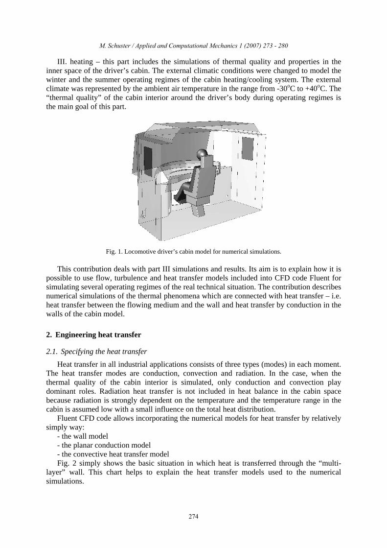
Numerical simulations allow to comprehensively solve ventilation, heating and air conditioning system for locomotive driver’s cabin. The computational domain was represented by the volume of the cabin inner space including a control desk and a body of driver with his seat (see fig. 1). Series of simulations were divided into three main parts:
I. design of ventilation system – this part includes a lot of simulation of air flow in several cabin models to find the optimal location of inlet/outlet vent holes on a control desk and console surface. Simulation process and results are shown in detail in recently works [1] and [2]. The velocity distributions for many vent holes versions were the results. The vent holes shapes and their location were the goal of this part.
II. ventilation with regulating state – this part includes simulations of air flow in cabin space in the case in which air rate was regulated and/or direction of air in inlet holes was changed. The first results of these simulations were published in [3]. The maps of air velocity distributions in cabin space were the main results of the simulations. These results were used as the basis for adjusting the cabin vent system.
*Corresponding author. Tel.: +420 378 182 209, e-mail: [email protected].
Applied and Computational Mechanics 1 (2007) 273 - 280
273
M. Schuster / Applied and Computational Mechanics X (YYYY) 123-456
III. heating – this part includes the simulations of thermal quality and properties in the inner space of the driver’s cabin. The external climatic conditions were changed to model the winter and the summer operating regimes of the cabin heating/cooling system. The external climate was represented by the ambient air temperature in the range from -30oC to +40oC. The “thermal quality” of the cabin interior around the driver’s body during operating regimes is the main goal of this part.
Fig. 1. Locomotive driver’s cabin model for numerical simulations.
This contribution deals with part III simulations and results. Its aim is to explain how it is possible to use flow, turbulence and heat transfer models included into CFD code Fluent for simulating several operating regimes of the real technical situation. The contribution describes numerical simulations of the thermal phenomena which are connected with heat transfer – i.e. heat transfer between the flowing medium and the wall and heat transfer by conduction in the walls of the cabin model.
2. Engineering heat transfer
2.1. Specifying the heat transfer
Heat transfer in all industrial applications consists of three types (modes) in each moment. The heat transfer modes are conduction, convection and radiation. In the case, when the thermal quality of the cabin interior is simulated, only conduction and convection play dominant roles. Radiation heat transfer is not included in heat balance in the cabin space because radiation is strongly dependent on the temperature and the temperature range in the cabin is assumed low with a small influence on the total heat distribution.
Fluent CFD code allows incorporating the numerical models for heat transfer by relatively simply way:
- the wall model - the planar conduction model - the convective heat transfer model Fig. 2 simply shows the basic situation in which heat is transferred through the “multi-
layer” wall. This chart helps to explain the heat transfer models used to the numerical simulations.
M. Schuster / Applied and Computational Mechanics 1 (2007) 273 - 280
274

M. Schuster / Applied and Computational Mechanics X (YYYY) 123-456
2.2. Heat conduction in cabin walls
Conductive heat transfer is caused by “diffusion” of heat due to temperature gradient. Heat flux q (W/m2) through the wall of thickness hi can be written:
( )s1s2i
i tth
q −λ= , (1)
where ts1 and ts2 are temperatures of cold or hot wall surface and λi (W/m.K) is thermal conductivity of the solid walls material. The locomotive cabin consists of “multi-layer” walls. They are composed of the external sheet metal layer, of several parts of the cabin body as beams or supports and finally of the noise and the thermal insulation layers (see fig. 2). In this case term (1) can be modified:
( )s1skN tt
hq −λ= , (2)
where h is the total thickness of the “multi-layer” wall. The total number of layers is n = k – 1. Nλ (W/m.K) is the modified thermal conductivity of the “multi-layer” wall, which
is:
∑ λ
=λ
n i
iN h
h , (3)
where number of layers is i = 1, 2, …., n.
Fig. 2. Basic scheme of conductive and convective heat transfer through the multi-layer wall (see text).
M. Schuster / Applied and Computational Mechanics 1 (2007) 273 - 280
275

M. Schuster / Applied and Computational Mechanics X (YYYY) 123-456
2.3. Heat convection near the cabin surface
Convective heat transfer arises when heat is carried away from the hotter body surface by moving fluid. Heat transfer q (W/m2) between hot cabin surface and cold ambient air (fig. 2 left) can be written:
( )exs1ext ttq −α= , (4)
where the values in parentheses are the temperatures of the cabin surface and the ambient air in accordance with fig. 2. Heat transfer coefficient extα (W/m2.K) is possible to determine
via the Nusselt number and the correlations describing heat transfer in the given conditions (5). In general these correlations may be expressed as:
( ) extm
ext Pr,...Re,fNu;L
Nu α⇒=λ
α=1
, (5)
where PrRe,,Nu are dimensionless numbers (Nusselt, Reynolds, Prandtl), L is reference
length and 1mλ (W/m.K) is the thermal conductivity of the ambient “medium 1”. To obtain
extα it is possible to use Nusselt correlation in the right part of (5), which is given by some
function f corresponding with the heat convection conditions (in the cabin case e.g. heat transfer from a flat plate in a turbulent flow for the given velocity range).
Conductive heat transfer between the inner cabin surface and the interior space is directly calculated by the Fluent CFD code. It means that it is not necessary to introduce the inner heat transfer coefficient intα (W/m2.K).
In this case, when driver’s cabin is highly ventilated, only forced convection was calculated in the heat balance.
The Fluent CFD code allows the heat transfer modelling. It is possible to calculate both the heat diffusion in heat-gradient direction normal to boundaries and the planar conduction in boundaries plane using the “thin wall” and the “shell conduction” models. The Fluent heat transfer models advantages are in their relative simplicity of setting the calculation of heat conduction in the cabin walls in normal direction, of the planar heat distribution and of heat convection on the external cabin surface. The wall grid generation was not needed in this approach.
3. Simulation of the locomotive cabin
The goal of the numerical simulations was to find the temperature fields and the temperatures values in the inner cabin space in the important points around the driver’s body as results of the influence of external climatic conditions. That is why the simulations were solved in three groups:
A. winter regime – average temperature of the ambient air was -30oC, B1. summer regime – average temperature of the ambient air was +40oC, B2. sunshine regime – the same like B1, but in the addition situation when the locomotive
is staying in a station (longer operational breaks) is modelled. Each of these operating regimes was modelled by the corresponding parameters of the
heat transfer models and boundary conditions. Ventilation and air circulation in cabin space was defined by the “velocity-inlet” boundary
condition type. The values of the velocities on the inlet vent holes were the same as in the foregoing simulations (see introduction section). These values are the results of the flow
M. Schuster / Applied and Computational Mechanics 1 (2007) 273 - 280
276
M. Schuster / Applied and Computational Mechanics X (YYYY) 123-456
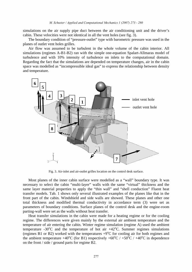
simulations on the air supply pipe duct between the air conditioning unit and the driver’s cabin. These velocities were not identical in all the vent holes (see fig. 3).
The boundary condition of “pressure-outlet” type with barometric pressure was used in the planes of outlet vent holes grilles.
Air flow was assumed to be turbulent in the whole volume of the cabin interior. All simulations (regimes A-B1-B2) ran with the simple one-equation Spalart-Allmaras model of turbulence and with 10% intensity of turbulence on inlets to the computational domain. Regarding the fact that the simulations are depended on temperature changes, air in the cabin space was modelled as “incompressible ideal gas” to express the relationship between density and temperature.
Fig. 3. Air-inlet and air-outlet grilles location on the control desk surface.
Most planes of the inner cabin surface were modelled as a “wall” boundary type. It was necessary to select the cabin “multi-layer” walls with the same “virtual” thickness and the same layer material properties to apply the “thin wall” and “shell conduction” Fluent heat transfer models. Tab. 1 shows only several illustrated examples of the planes like that in the front part of the cabin. Windshield and side walls are showed. These planes and other one total thickness and modified thermal conductivity in accordance term (3) were set as parameters of boundary conditions. Surface planes of the control desk and the engine-room parting-wall were set as the walls without heat transfer.
Heat transfer simulations in the cabin were made for a heating regime or for the cooling regime. The differences were given mainly by the external air ambient temperature and the temperature of air entering the cabin. Winter regime simulation (regime A) used the ambient temperature -30oC and the temperature of hot air +42oC. Summer regimes simulations (regimes B1 or B2) worked with the temperatures +9oC for cooling air for both regimes and the ambient temperature +40oC (for B1) respectively +60oC / +50oC / +40oC in dependence on the front / side / ground parts for regime B2.
6 5
4 3 2 1
inlet vent hole
outlet vent hole
7
8
M. Schuster / Applied and Computational Mechanics 1 (2007) 273 - 280
277

M. Schuster / Applied and Computational Mechanics X (YYYY) 123-456
windshield – laminated safety glass and perspex side walls – metal, insulation, plastics combination
side doors - metal, insulation, plastics combination side double windows – glass, air
Tab. 1. Several planes of the cabin for the conductive and convective heat transfer boundary conditions setting (only illustrating selection of the walls).
Results of the simulations of all three thermal regimes were used to check the quality of the thermal conditions in the cabin and to improve the driver’s comfort. The results were compared with the values given in the standards [4], [5]. Lots of results in the form of the temperature fields in important planes or points mostly near the driver’s body and in the form of many combinations of parameters were created.
The illustrating selection of the obtained results was published in this contribution. These results only in the form of black/white pictures of the temperature fields in the planes 100 mm above the floor level and 100 mm under the roof of the cabin allow to give basic information about the flow and the thermal situation in the cabin interior. These temperature fields on both planes are required by the standards to evaluate the temperature differences between planes and their value compare with standards.
The temperature fields for the winter regime (A) are in figs. 4 and 5. They indicate the temperature distribution in the cabin and the value of temperature about 28oC near the driver’s body. Those values show, that heating system in maximal output is able to sufficiently heat the cabin. Figs. 6 and 7 show the temperature fields for the summer regime (B1). It is evident that the temperature around 18oC near the driver shows that also cooling system of cabin is in order.
M. Schuster / Applied and Computational Mechanics 1 (2007) 273 - 280
278

M. Schuster / Applied and Computational Mechanics X (YYYY) 123-456
Fig. 4. The temperature field on the plane 100 mm above the floor level for winter operating regime (A).
Fig. 5. The temperature field on the plane 100 mm under the cabin roof for winter operating regime (A).
Fig. 6. The temperature field on the plane 100 mm above the floor level for summer operating regime (B1).
M. Schuster / Applied and Computational Mechanics 1 (2007) 273 - 280
279

M. Schuster / Applied and Computational Mechanics X (YYYY) 123-456
Fig. 7. The temperature field on the plane 100 mm under the cabin roof for summer operating regime (B1).
4. Conclusion
This contribution deals with the simulations of the thermal phenomenon which arise in the driver’s cabin during the heating or cooling regimes. The main part of the contribution describes the possibilities of engineering heat transfer simulations. The Fluent CFD code models were created and verified to be used for the convective and conductive heat transfer calculations. The Fluent heat transfer models were used for the simulation of the thermal conditions in the cabin inner space during the extremes – heating for winter and cooling for summer.
The obtained results of these simulations enabled to confirm that the designed air-conditioning system with the tested power-output is able with reserve to keep comfortable conditions in the cabin. The average values of air temperatures near the driver’s body are more than 24oC for a heating regime (A) and less than 18oC for a cooling regime (B1 and B2) and they satisfy the standard requirements.
The methodology of heat transfer modelling described in this contribution will be used in next simulations of the similar driver’s cabins of loco, railcars, tramways etc. in the future.
Acknowledgement
The work has been supported by the research project No. 1M0519 – Research Centre of Rail Vehicles supported by the Czech Ministry of Education, Youth and Sports.
References
[1] M. Schuster, Driver’s cabin ventilation, Proceedings of the 21st Conference “Computational mechanics 2005”, Nečtiny, University of West Bohemia in Pilsen, 2005, pp. 535-542 (in Czech).
[2] M. Schuster, Contribution to the simulations of flow during driver’s cabin ventilation, Book of extended abstracts of the Conference “Engineering mechanics”, Svratka, Institute of Theoretical and Applied Mechanics of Academy of Sciences, 2005, pp. 326-327 (in Czech).
[3] M. Schuster, Properties of flow in the vehicle interior, Proceedings of the 22nd Conference on Computational mechanics, Nečtiny, University of West Bohemia in Pilsen, 2006, pp. 559-566 (in Czech).
[4] ON (TNŽ) 28 5201, Czech technical standard (in Czech). [5] UIC 651, Layout of driver’s cabs in locomotives, UIC standard.
M. Schuster / Applied and Computational Mechanics 1 (2007) 273 - 280
280