simulation of orthogonal cutting with smooth particle
TRANSCRIPT

SANDIA REPORTSAND97–1961 Ž UC–705Unlimited ReleasePrinted September 1997
Simulation of Orthogonal Cutting withSmooth Particle Hydrodynamics
Martin Heinstein, Dan Segalman
Prepared bySandia National LaboratoriesAlbuquerque, New Mexico 87185 and Livermore, California 94550
Sandia is a multiprogram laboratory operated by Sandia Corporation,a Lockheed Martin Company, for the United States Department ofEnergy under Contract DE-AC04-94AL85000.
Approved for public release; distribution
Sandia National
is unlimited.
laboratories

Issued by Sandia National Laboratories, operated for the United StatesDepartment of Energy by Sandia Corporation.
NOTICE: This report was prepared as an account of work sponsored by anagency of the United States Government. Neither the United States Govern-ment nor any agency thereof, nor any of their employees, nor any of theircontractors, subcontractors, or their employees, makes any warranty,express or implied, or assumes any legal liability or responsibility for theaccuracy, completeness, or usefulness of any information, apparatus, prod-uct, or process disclosed, or represents that its use would not infringe pri-vately owned rights. Reference herein to any specific commercial product,process, or service by trade name, trademark, manufacturer, or otherwise,does not necessarily constitute or imply its endorsement, recommendation,or favoring by the United States Government, any agency thereof or any oftheir contractors or subcontractors. The views and opinions expressedherein do not necessarily state or reflect those of the United States Gover-nment,any agency thereof or any of their contractors.
Printed in the United States of America. This report has been reproduceddirectly from the best available copy.
Available to DOE and DOE contractors fi-omOffice of Scientific and Technical InformationPO BOX 62Oak Ridge, TN 37831
Prices available from (615) 576-8401, FTS 626-8401
Available to the public fromNational Technical Information ServiceUS Department of Commerce5285 Port Royal RdSpringfield, VA 22161
NTIS price codesPrinted copy A08Microfiche copy AO1

SAND97-1961 DistributionUnlimited Release Category UC-705
Printed September 1997
Simulation of Orthogonal Cutting withSmooth Particle Hydrodynamics
Martin Heinstein
Engineering and Manufacturing Mechanics Departmentand
Dan Segalman
Structural Dynamics and Vibration Control Department
Sandia National Laboratories
P.O.Box 5800Albuquerque, NM 87185-0439
ABSTRACT
There is an active literature on the simulation of cutting processes through finite element methods.Such efforts are motivated by the enormous economic importance of machining processes and thedesire to adjust processes so as to optimize product and throughput, but suffer from some difficul-ties inherent to the finite element method. An alternative approach, which appears to overcomemost of those difficulties. is that of Smooth Particle Hydrodynamics (SPH). Though some finiteelement work is reviewed here, the focus of this paper is on the demonstration of the SPH tech-nique of to simulate orthogonal cutting.
. ..


Contents
Introduction ............................................................................................................. 1
Smooth Particle Hydrodynamics ............................................................................lMaterial Failure Modeling ......................................................................................3Cutting Simulations ................................................................................................3Conclusions .............................................................................................................9References ...............................................................................................................9
Figures
Smooth Particle Hydrodynamics (SPH) is used to solve the governing equations in thevicinity of the cutting process. Feed force, cutting force and cutting tool momentreactions are evaluated at boundaries that are far from the cutting interface ..... 4
A finite element calculation of orthogonal cuttingofAl6061-T6 in which materialseparation is achieved by “killing off’ elements that experience excessive plasticstrain. ................................................................................................................... 5
SPH simulation of cutting Aluminum 6061-T6 at various rake angles and feeds (sometimesreferred to as depth of cut). ................................................................................. 6
SPH simulation of cutting of Al 6061-T6 at a rake angle of -45°. ........................... 7SPH calculations exploring the qualitative effect of mesh refinement for the case of a 30°
rake angle. ........................................................................................................... 7SPH calculations exploring the qualitative effect of mesh refinement for the case of a
negative 30° rake angle. ...................................................................................... 8Convergence of the SPH calculation is investigated by examination of the convergence of
reaction forces and moments on the cutting tool. ............................................... 8

< +..

Introduction
Simulation of Orthogonal Cutting withASmooth Particle Hydrodynamics”
Introduction
Classic methods such as slip lines, e.g. Merchant [1] and Lee and Shaffer [2], have beenused in the past to explore the cutting process and to predict cutting forces. These methodsrequire severe kinematic assumptions and are somewhat limited to simplified material(constitutive) response. Resorting to weighted residual techniques involving basis func-tions with only local support is therefore desirable and often necessary to solve the fieldequations. Several efforts have been made using the finite element method, see e.g. Stren-kowski [3, 4], Shih [5]. However, several deficiencies of the finite element method in thesimulation of cutting remain:
● the propensity of individual elements to be turned inside out as the material undergoesvery large deformations in the vicinity of the cutting tool;
● the difficulty of accommodating material failure (separation) within the finite elementmesh;
● the uncertainty and ambiguity of implementing material failure criteria during cutting.
Recently, Maraush [6] has shown that aggressive re-meshing may be used to circumventsevere mesh distortion. However, there is a substantial cost associated with re-meshingand there is uncertainty in preserving material state variables in the re-mapping process.Approaches to addressing the second of these issues are discussed in the literature and agood review can be found in [6], yet in general this issue awaits satisfactory resolution.
Because of the above fundamental uncertainties, most simulation focuses on orthogonalcutting, where these research issues can be attacked with relatively little expense.
In this paper, the natural manner in which the SPH method meets many of these chal-lenges is presented. The issue of material failure criteria during cutting appears to be asdifficult in this approach as in the others.
Smooth Particle Hydrodynamics
The method of “smooth particle hydrodynamics” is reviewed in Benz [7] and discussed inother perspectives in that paper. Just a minimal discussion of this technique is given herefor the purpose of clarity and continuity. SPH consists of a collection of nodes each having
*This work was supported by LDRD case number 3507270000.

Simulation of Orthogonal Cutting with Smooth Particle Hydrodynamics
physical degrees of freedom. The nodes have no fixed connectivity. Instead, the instanta-neous connectivity is determined from proximity of nodes to near neighbors, using a
search technique. The nodal contribution to the field quantity, ~, at a location 1 is:
(1)
where ~n is the field value associated with node n and IV(A – in, h) is the corresponding
shape function. The shape function is centered on the node n and can take many forms
(several are discussed in [7]) but must satisfy specific requirements. It must be sphericallysymmetric and integrate to unity, i.e.
pf-’)—“2=1,h
(2)
decay monotonically from its reference node t., and be zero beyond a distance of h, i.e.
have local support. The shape function used here is a cubic spline:
(3)
[ o otherwise
One of the most important features of SPH is the manner in which the gradient of the fieldquantity is computed. It can be shown that the contribution of a nodal value to the gradient
of the field at 2 is fnV W (2 – ?n, h). Note that the gradient remains meaningful no matter
how neighboring nodes are rearranged. In this way the SPH method obviates the problemof element distortion common to finite elements in problems of large shear. Finally, pointmasses are associated with each node (also referred to as particles).
In the case of the explicit transient dynamic simulation such as used here, the momentumequation:
(4)() . p3Jv) + v“~
is solved using a central difference time integrator. In equation (4), p is the material den-
sity, v is the material velocity and o is the Cauchy stress. Using the above gradient meth-
ods for evaluating the strain rate from the velocity field, and using appropriate constitutiveequations, stress increments can be calculated. Finally, the divergence of the stress field is
evaluated, and each node occupying a volume V with mass p V is accelerated accordingly.
In this manner the motion of the nodes is driven by the mechanics being simulated. We

Material Failure Modeling
note that relevant field quantities are re-evaluated at each time step and at each 1/2 timestep as required by the central difference time integrator.
Unfortunately, a recent stability analysis of SPH has shown the SPH gradient operator tobe only conditionally stable. A numerical technique called conservative smoothing seemsto stabilize the SPH algorithm in explicit transient dynamics applications at the expense ofintroducing some numerical diffusion. Further details on this can be found in Swegle, et.al. [8, 9] and Wen et. al. [10].
Material Failure Modeling
Calculating separation through material failure modeling is another of the difficult issuesin cutting simulation. One method used in finite element analysis to address this issue is toevaluate damage on each element and to remove those that suffer darnage beyond somespecified level. The obvious deficiency of this approach is that a significant part of thematerial volume is removed from the calculation unless an excessively fine mesh is used.
Another method used to attempt to capture material failure requires postulating the locusof material separation. A special layer of contact elements are placed on that path and sep-aration is permitted as some break-away load is achieved. The deficiencies of thisapproach are not only that it lacks theoretical rigor, but that implementation of it in thecontext of large-deformation plasticity is a logistical ordeal.
The kinematics of material separation are accommodated in SPH in a manner that neitherinvolves the loss of material, requires foreknowledge of the locus of separation, norrequires special numerical treatment. Material damage is incorporated at SPH nodesthrough a loss of cohesion as neighboring SPH particles separate from each other. This
comes about because once those particles are more than the critical distance, h, from each
other, each particle no longer contributes to the strain calculated at the other and the corre-sponding cohesive component of the stress disappears.
Though the SPH method offers advantages over the finite element methods in terms ofaccommodating the large deformations and the kinematic issues of material failure model-ing, the problem of dcfi ning physical criteria (such as failure strain, failure stress, or fail-ure energy) for ma~enal separation remains. That problem is a continuing topic forresearch.
Cutting Simulations
Orthogonal cutting problems involve passing a relatively hard tool through a softer work-piece, and this process is appropriately simulated by solving the nonlinear governingequations in a region very near the cutting tool. (See Figure 1). In this local problem, kine-matic boundary conditions are applied suitably far from the cutting tool/work-piece inter-face, providing relative motion between work-piece and tool. As a result, feed force,

Simulation of Orthogonal Cutting with Smooth Particle Hydrodynamics
cutting force and cutting tool moment reactions are evaluated at boundaries that are alsofar from the cutting interface.
,Ff = Feed force
‘d;dYWork iece
IIJ
boun ary conditio
Figure 1. Smooth Particle Hydrodynamics (SPH) is used to solve the governingequations in the vicinity of the cutting process. Feed force, cutting force and cuttingtool moment reactions are evaluated at boundaries that are far from the cutting inter-face
In the simulations done here, the tool is assumed to be elastic with properties: elastic mod-
ulus E=30E6 psi, Poisson ratio v = 0.3. The aluminum 6061-T6 work-piece material is
modeled as elastic, hardening-plastic. We note that, like the finite element method, theSPH method will admit any reasonable (or unreasonable) material constitutive model. Theone used here is a power law hardening with failure model described in Stone, et. al. [1 1].The criterion for material failure in this model is the equivalent plastic strain modified bythe maximum tensile and the mean (hydrostatic) pressure. Importantly, this captures twowell known effects: much higher likelihood of failure with positive maximum principalstress and decreased ductility in the presence of hydrostatic tension.
The cutting process simulated here includes inertial effects, but is assumed to be slow rel-ative to thermal conduction so that temperature effects are ignored. Because of uncertaintyin the nature of sliding during cutting, surface sliding is assumed to occur with a uniform
4

Cutting Simulations
coefficient of friction p = 0.5 in the calculations presented here.
FE Example:
The first simulation is an illustration of the finite element method applied to the orthogonal
cutting of aluminum 6061 -T6 (Figure 2). This particular simulation accommodates mate-
rial separation and material failure by “killing off” elements that undergo equivalent plas-
tic strain beyond some critical level. We note that material failure characterized by the
equivalent plastic strain exceeding a critical level is known to have significant error, espe-
cially under non-tensile loadings. In fact the failure criterion developed in [11] accounts
for damage accumulation under general non-tensile loading conditions. However, applica-
tion of this material model described in [11] to the orthogonal cutting problem resulted in
severe (numerically fatal) mesh distortion when applied to this problem.
Yet even with a critical level of equivalent plastic strain dictating failure, the characteris-
tics of element death can be observed. Figure 2 shows the sensitivity of the results to the
value of that critical plastic strain. We see some amount of surface discontinuity - proba-
bly quite acceptable - due to the missing elements. Particularly in the case where elements
are permitted to undergo the larger level of plastic strain, some elements suffer extreme
distortion: endangering both stability and accuracy. Refinement of the mesh exacerbates
this problem.
Critical EquivalentPlastic Strain = 1.2
-
0 1.2
,.vM#.>~*,~,.
Critical EquivalentPlastic Strain = 2.0
0’ 2.0
Figure 2. A finite element calculation of orthogonal cutting of Al 6061-T6 in whichmaterial separation is achieved by “killing off” elements that experience excessive plasticstrain.
SPH Example:
Figure 1, shown earlier, presents the results of using SPH to simulate the same cutting
conditions. Additional cases explore the effects of rake angle and feed are shown in

Simulation of Orthogonal Cutting with Smooth Particle Hydrodynamics
Fi
+5° rake, .005 doc +5° rake, .01 doc
+10° rake, .01 doc -5° rake, .005 doc
-5° rake, .01 doc -10° rake, .01 doc
Figure 3. SPH simulation of cutting Aluminum 6061-T6 at various rake anglesand feeds (sometimes referred to as depth of cut).
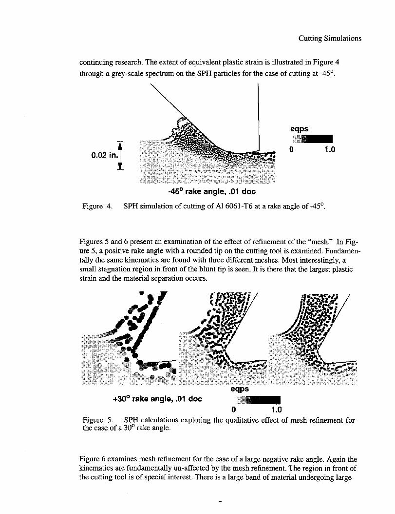
Note that negative rake angle is accommodated with no more difficulty than positive rakeangle. In fact, Figure 4 shows a simulation with a rake angle of-45 degrees.
Figure 4 also shows some incipient cleavage lines in the substrate material about 0.025inches below the tool tip. These physically incorrect separations are a manifestation of aninstability in the SPH process discussed by Swegle et. al. [9]. Though this incipient insta-bility would grow with time, the growth rate is slow enough that it does not interfere withthe simulation. Development of methods to obviate or avoid this instability is a topic of
Cutting Simulations
continuing research. The extent of equivalent plastic strain is illustrated in Figure 4
through a grey-scale spectrum on the SPH particles for the case of cutting at -45°.
f0.02 in.
eqps
o 1.0
-45° rake angle, .01 doc
Figure 4. SPH simulation of cutting of Al 6061-T6 at a rake angle of -45°.
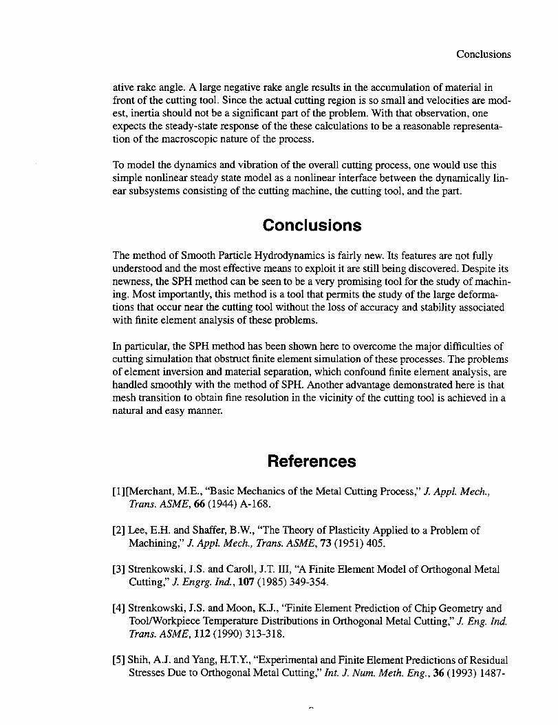
Figures 5 and 6 present an examination of the effect of refinement of the “mesh.” In Fig-ure 5, a positive rake angle with a rounded tip on the cutting tool is examined. Fundamen-tally the same kinematics are found with three different meshes. Most interestingly, asmall stagnation region in front of the blunt tip is seen. It is there that the largest plasticstrain and the material separation occurs.
eqps+30° rake angle, .01 doc ,~
o 1.0Figure 5. SPH calculations exploring the qualitative effect of mesh refinement forthe case of a 30° rake angle.
Figure 6 examines mesh refinement for the case of a large negative rake angle. Again thekinematics are fundamentally un-affected by the mesh refinement. The region in front ofthe cutting tool is of special interest. There is a large band of material undergoing large
7

Simulation of Orthogonal Cutting with Smooth Particle Hydrodynamics
plastic strain as the material rotates in shear in front of the cutting tool
-30° rake angle, .01 doc
Figure 6. P PSPH calculations exploring the qua ltative effect% mesh refinement for thecase of a negative 30° rake angle.
Finally, we present the steady-state forces for the condition of +30 degree rake angle and0.01 in. d.o.c in Figure 7 as a function of mesh refinement. One sees apparent convergenceon net tool force and moment as the mesh is refined.
500”0 ~JF
400.0+-
m:
* Rx (lb/in)300.0 - + Ry (lb/in)
A M in-lb/in200.0 -
100.0,~ i~4L
0.0coarse fine very fine
mesh refinement
Figure 7. Convergence of the SPH calculation is investigated by examination of theconvergence of reaction forces and moments on the cutting tool.
We note that qualitatively correct predictions are generated for each case of rake angle. Inparticular, we see normal chip formation in the cases of positive rake angle and small neg-
8
Conclusions
ative rake angle. A large negative rake angle results in the accumulation of material infront of the cutting tool. Since the actual cutting region is so small and velocities are mod-est, inertia should not be a significant part of the problem. With that observation, oneexpects the steady-state response of the these calculations to be a reasonable representa-tion of the macroscopic nature of the process.
To model the dynamics and vibration of the overall cutting process, one would use thissimple nonlinear steady state model as a nonlinear interface between the dynamically lin-ear subsystems consisting of the cutting machine, the cutting tool, and the part.
Conclusions
The method of Smooth Particle Hydrodynamics is fairly new. Its features are not fullyunderstood and the most effective means to exploit it are still being discovered. Despite itsnewness, the SPH method can be seen to be a very promising tool for the study of machin-ing. Most importantly, this method is a tool that permits the study of the large deforma-tions that occur near the cutting tool without the loss of accuracy and stability associatedwith finite element analysis of these problems.
In particular, the SPH method has been shown hereto overcome the major difficulties ofcutting simulation that obstruct finite element simulation of these processes. The problemsof element inversion and material separation, which confound finite element analysis, arehandled smoothly with the method of SPH. Another advantage demonstrated here is thatmesh transition to obtain fine resolution in the vicinity of the cutting tool is achieved in anatural and easy manner.
References
[l][Merchant, M.E., “Basic Mechanics of the Metal Cutting Process;’ J. AppL A4ech.,Trans. ASME, 66 (1944) A-168.
[2] Lee, E.H. and Shaffer, B.W., “The Theory of Plasticity Applied to a Problem ofMachining~’ J. AppL h4ech., Trans. ASME, 73 (195 1) 405.
[3] Strenkowski, J.S. and Caroll, J.T. III, “A Finite Element Model of Orthogonal MetalCutting:’ J. Engrg. k-l., 107 (1985) 349-354.
[4] Strenkowski, J.S. and Moon, K.J., “Finite Element Prediction of Chip Geometry andTool/Workpiece Temperature Distributions in Orthogonal Metal Cutting:’ J. Eng. Ind.Trans. ASME, 112 (1990)313-318.
[5] Shih, A.J. and Yang, H.T.Y., “Experimental and Finite Element Predictions of ResidualStresses Due to Orthogonal Metal Cutting;’ Znt. J. ZVwn.Meth. Eng., 36 (1993) 1487-
9

Simulation of Orthogonal Cutting with Smooth Particle Hydrodynamics
1507.
[6] Marusich, T.D., “Finite Element Simulation of High Speed Machining Processes;’PhD Thesis Brown University, 1996.
[7] Benz, W., “Smooth Particle Hydrodynamics: A Review:’ Harvard-Smithsonian Centerfor Astrophysics, Preprint Series No. 2884 (1989).
[8] Swegle, J.W., Hicks D.L., and Attaway, S.W., “Smoothed Particle Hydrodynamics Sta-bility Analysis:’ Journal of Computational Physics, Vol. 116, (1995) pp. 123-134.
[9] Swegle, J.W., Attaway, S.W., Heinstein, M.W., Mello, F.J., and Hicks D.L., and “AnAnalysis of Smooth Particle Hydrodynamics;’ SAND93-25 13, Sandia National Labo-ratories, Albuquerque, NM, 1993.
[10] Wen, Y., Hicks D.L., and Swegle, J.W., “Stabilizing SPH with Conservative Smooth-ing,” SAND94- 1932, Sandia National Laboratories, Albuquerque, NM, 1994.
[11 ] Stone, C.M., Wellman G.W., and Krieg, R. D., “A Vectorized Elastic/Plastic PowerLaw Hardening Material Model Including Luders Strain;’ SAND90-0153, SandiaNational Laboratories, Albuquerque, NM, 1990.

DistributionMS0960 01400MS0961 01403MS9042 02271MS9430 08204MS9430 08240MS9430 08240MS0841 09100MS0443 09117MS0443 09117
MS0437 09118MS0437 09118MS0437 09118MS0321 09200MS0439 09234MS0439 09234MS0439 09234MS0439 09234
1 MS01881 MS 90185 MS 08992 MS 0619
Searcy,JirnmieQ.Plymale,DonaldL.McDonald,AlfredoTallerico,LouieN.King, CalvinWest, Anton J.Homrnert, Paul J.Morgan, Harold S.Heinstein, Martin W. (15)Thomas, Robert K.Attaway, Stephen W.Swegle, Jeffrey W.Camp, William J.Martinez, David R.Redmond, James M.Hinnerichs, TerrySegalman, Daniel J. (15)
LDRD OfficeCentral Technical Files, 8940-2Technical Library, 4416Review & Approval Desk, 12690For DOE/OSTI