simulation of analog and digital circuits with the ......simulation of analog and digital circuits...
TRANSCRIPT

Session 3548
Simulation of Analog and Digital Circuits with the Electronic Workbench
Massoud M. RabieeEastern Kentucky University
Abstract:
The improvement of software to simulate electrical circuits has been tremendous in recent years. The newversion of Electronic Workbench for Windows (EWB 4.0) is a user friendly simulation program [1]. This paperwill focus on providing information on how to use the EWB 4.0 simulation software in the classroom. Studentscan use this program to design and simulate their Analog, and Digital circuit assignments prior to actual buildingof the circuit(s) in the laboratory. This paper intends to familiarize the reader with simulation software, inparticular, with the Electronic Workbench for Windows version 4.0.
Introduction:
We will first explain the commands, and the method of drawing an electric circuit on the EWB 4.0 screen. Then,we will describe the Component Icon groups, and the Instrument Icons. Five examples will show the convenienceand the speed of Electric and Electronic circuit simulations. In the first example we will discuss the use of afunction generator, oscilloscope, multimeter, ammeters, and voltmeters to supply and display AC and DC signals.The second example will be a two-stage amplifier with a voltage gain of two. In the third example, the Bode Plotterwill be used to display the magnitude, and phase shift of a notch Operational Amplifier (Op-Amp) filter. In thefourth example, the Logic Converter is used to construct a Combinational Logic circuit from a Truth Table. Next,we will use the Word generator, and the Logic Analyzer to display the Timing Diagram of the digital circuit.Finally, in the last example, we will analyze a Sequential and Hybrid Logic circuit. Also, we will show how tosimulate four-way switches using single-pole, single-throw (SPST) switches.
Analog Circuit Simulation:
We select the components by clicking on the component and dragging it to the desired position on the screen.We may use the Circuit command to select the appropriate component group prior to the component selection.Once we have placed the components on the circuit, we should connect wires to complete the circuit. Click on anode of a component, and drag the mouse over to a node on another component. The two components will connect. 1Double click on the wire, and select the color for that wire. Note that we use different wire colors in order to havemulticolor signals on the Oscilloscope. After completing the circuit, we are ready to use the instruments availablein the software to analyze the circuit. Figure 1 displays the Electronic Workbench’s analog instruments.
~ .,,,>{~~j 1996 ASEE Annual Conference Proceedings‘O$lylly
Page 1.388.1
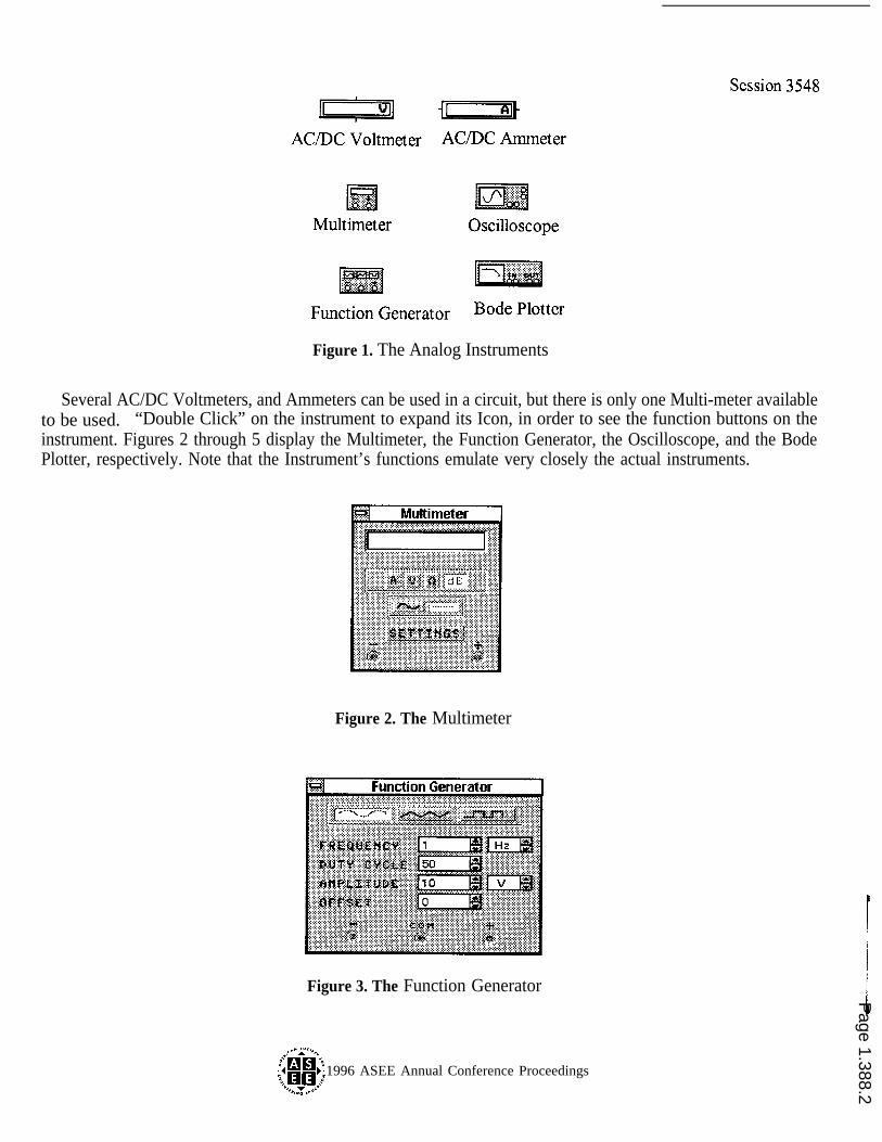
Figure 1. The Analog Instruments
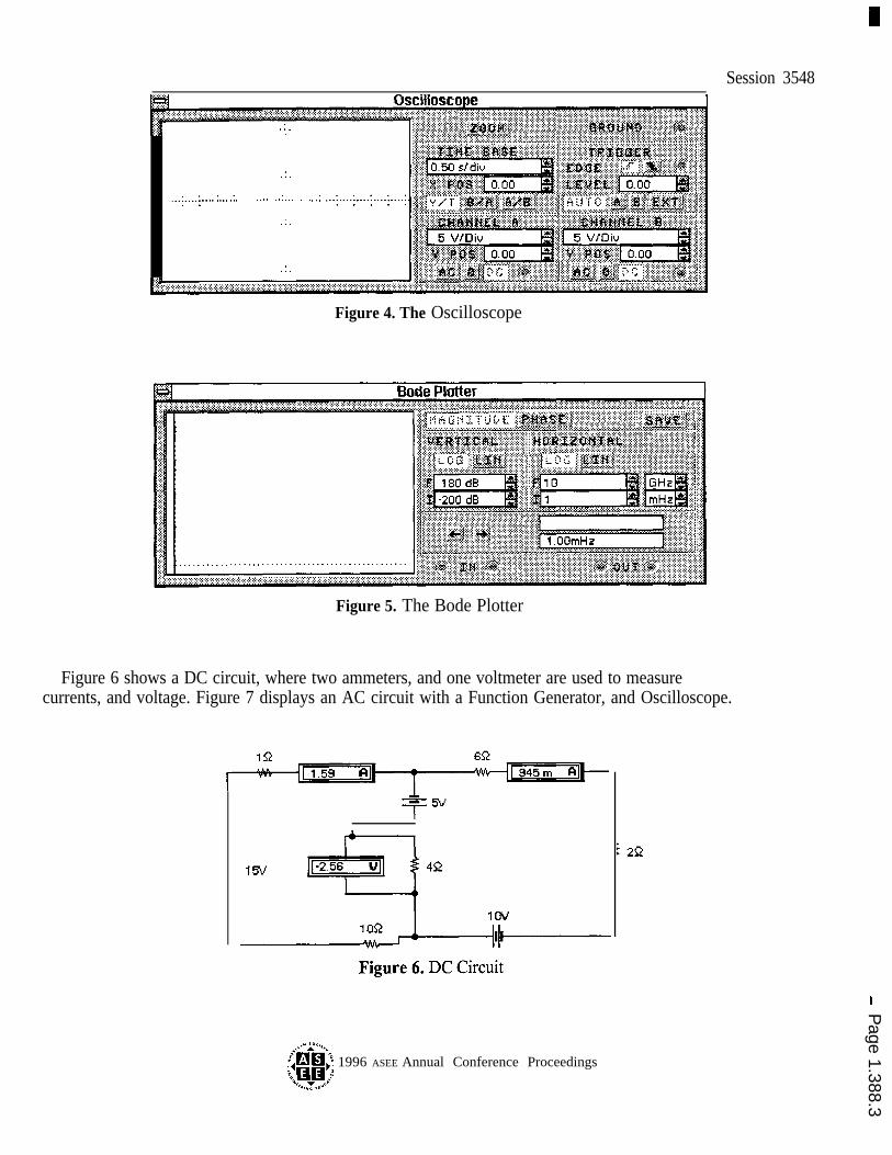
Several AC/DC Voltmeters, and Ammeters can be used in a circuit, but there is only one Multi-meter availableto be used. “Double Click” on the instrument to expand its Icon, in order to see the function buttons on theinstrument. Figures 2 through 5 display the Multimeter, the Function Generator, the Oscilloscope, and the BodePlotter, respectively. Note that the Instrument’s functions emulate very closely the actual instruments.
Figure 2. The Multimeter
Figure 3. The Function Generator
?$!iii’} 1996 ASEE Annual Conference Proceedings‘.,,<~ym’,.$
Page 1.388.2
Session 3548
,. :..,. .:.
.:.
. . . . . . . . . . . . . . . .
.:.
,. .:,
.:.
Figure 4. The Oscilloscope
Figure 5. The Bode Plotter
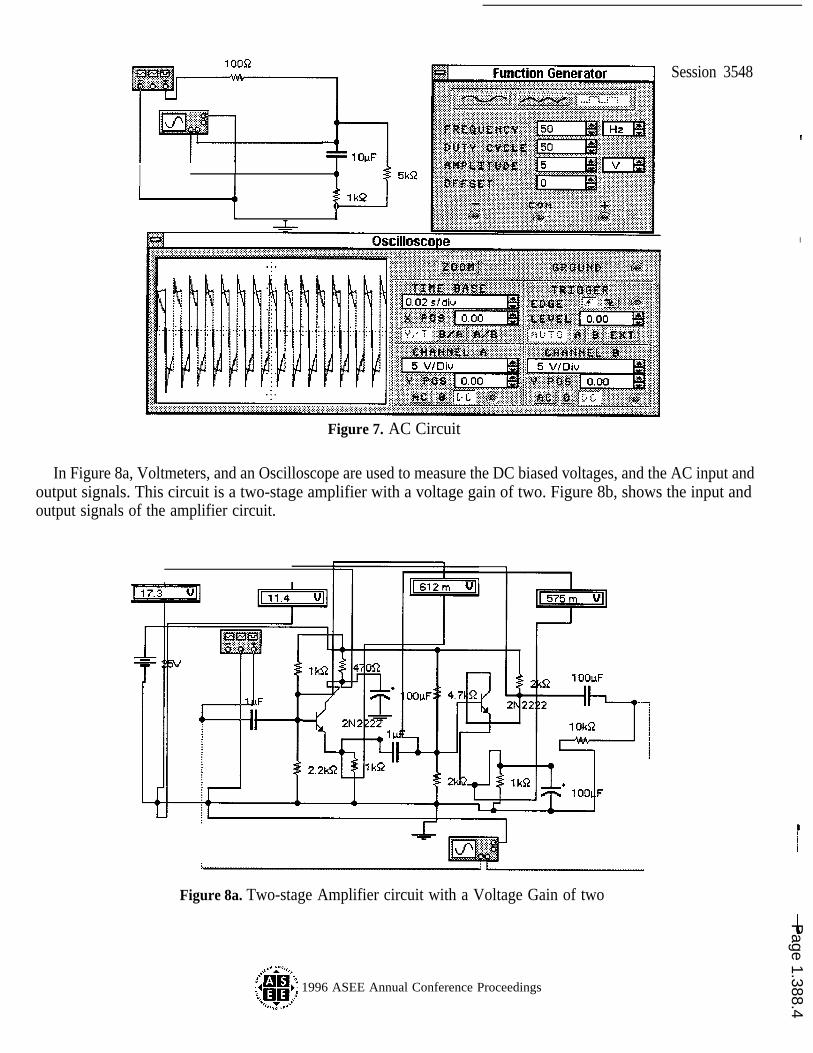
Figure 6 shows a DC circuit, where two ammeters, and one voltmeter are used to measurecurrents, and voltage. Figure 7 displays an AC circuit with a Function Generator, and Oscilloscope.
{hxh’~ 1996 ASEE Annual Conference Proceedings‘.,plypj
Page 1.388.3
I1
TI
Session 3548
I
Figure 7. AC Circuit
In Figure 8a, Voltmeters, and an Oscilloscope are used to measure the DC biased voltages, and the AC input andoutput signals. This circuit is a two-stage amplifier with a voltage gain of two. Figure 8b, shows the input andoutput signals of the amplifier circuit.
Figure 8a. Two-stage Amplifier circuit with a Voltage Gain of two
$i!ii’-’> 1996 ASEE Annual Conference Proceedings‘..,~ycllllc.:.
Page 1.388.4

Session 3548
Figure 8b. Input and Output signals of the circuit in figure 8a
Figure 9 shows a notch OP-Amp filter. The Bode Plotter displays the amplitude characteristic of this filter. Thiscircuit will filter out 60 Hz AC hum from any low voltage audio source. The cutoff frequency is determined by theequation.
1--------
2Pi*R*CWhere, RI =R2=R3=R4=R5=R,
Figure 9. A Notch Op-Amp Filter
{tix~~ 1996 ASEE Annual Conference Proceedings‘.,,,~yM1’:
Page 1.388.5
Session 3548Digital Circuit Simulation:
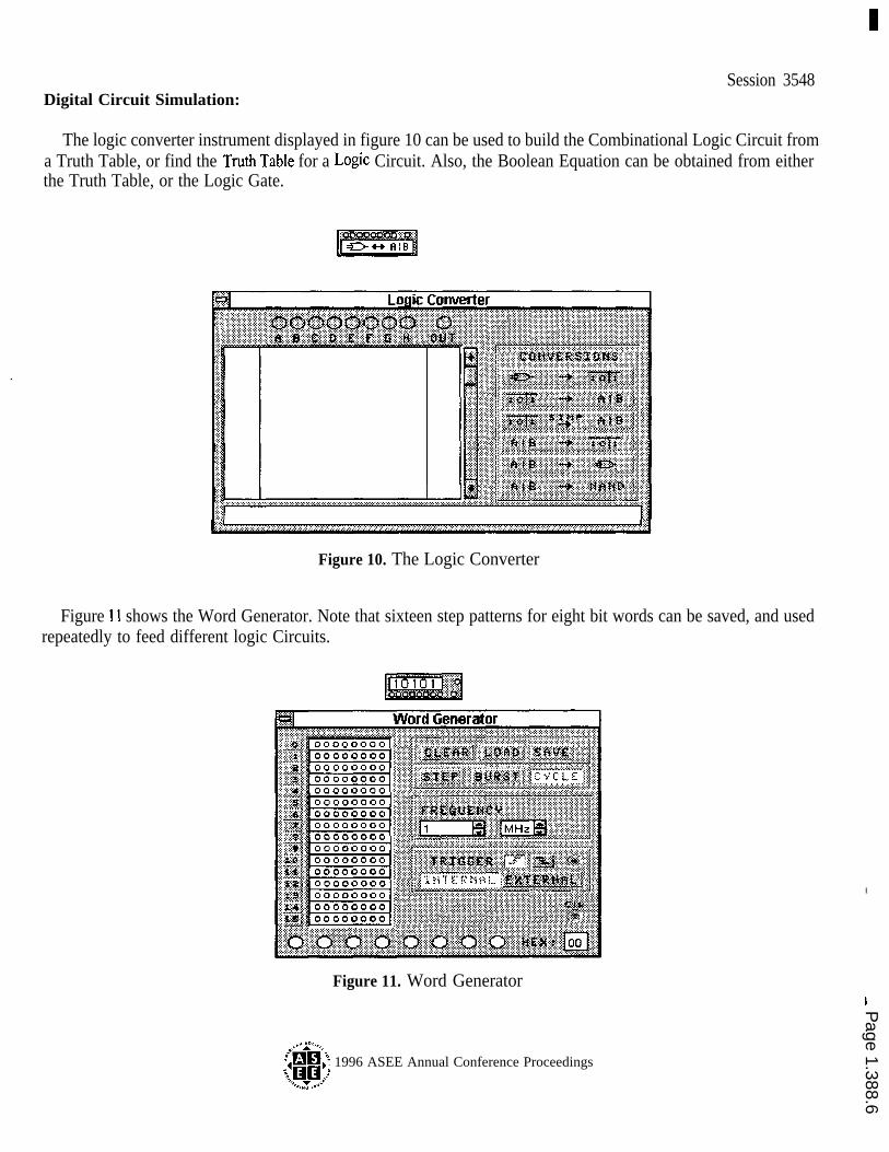
The logic converter instrument displayed in figure 10 can be used to build the Combinational Logic Circuit froma Truth Table, or find the Truth Table for a LO@C Circuit. Also, the Boolean Equation can be obtained from eitherthe Truth Table, or the Logic Gate.
Figure 10. The Logic Converter
Figure 11 shows the Word Generator. Note that sixteen step patterns for eight bit words can be saved, and usedrepeatedly to feed different logic Circuits.
I
Figure 11. Word Generator
?~~x~j 1996 ASEE Annual Conference Proceedings‘Jlllllllll’:
Page 1.388.6
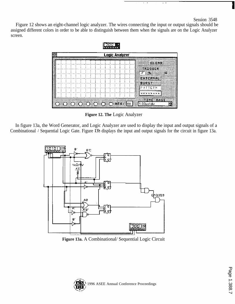
Session 3548Figure 12 shows an eight-channel logic analyzer. The wires connecting the input or output signals should be
assigned different colors in order to be able to distinguish between them when the signals are on the Logic Analyzerscreen.
Figure 12. The Logic Analyzer
In figure 13a, the Word Generator, and Logic Analyzer are used to display the input and output signals of aCombinational / Sequential Logic Gate. Figure 13b displays the input and output signals for the circuit in figure 13a.
Figure 13a. A Combinational/ Sequential Logic Circuit
{hii$~ 1996 ASEE Annual Conference Proceedings‘O.,,yyllll’j
Page 1.388.7

. . . . . .
Figure 13b. Input and Output signals for the circuit in figure 13a
Session 3548
Figure 14 displays a circuit in which both analog and digital components are used. The buzzer will soundwhenever the count reaches “F” (hex), that is “15” (decimal).
Figure 14. Binary Counter Circuit
Simulating Four-Way Switch:
Figure 15 shows a lighting circuit for a commercial building. The 4-Way switch is often used in halls, andlarge conference rooms. The switch can make, or break using one of the three switches located in differentpositions. In the figure single-pole, single-throw (SPST) switches are used to simulate and illustrate theelectrical connection of the four-way switch. Pressing either the S-key, T-key, or the space-bar on thecomputer keyboard will cause the 75 watt light bulb to turn on, or off.
?$i!iiii’} 1996 ASEE Annual Conference Proceedings‘..,,~y~c.!.
Page 1.388.8

Session 3548
I
Figure 15. Simulating 4-way Switch
Conclusion:
This paper intended to introduce the simulation power, and flexibility of Electronic Workbench for Windows.During the presentation at the 1996 ASEE Annual Conference, the author will familiarize the participants with themethod of using this package to simulate different types of electronic circuits. The benefits of using simulationsoftware before the actual connection of the circuit, and signal measurement is substantial. Students will have agood understanding of how the circuit will operate, and what the signals should look like. For further informationon Electronic Workbench the reader needs to contact the Interactive Image Technologies Ltd., at 1-800-203-8007.
Reference:
1. Electronic Workbench for Windows 4.0, Interactive Image Technologies Ltd., 700 King Street W, Suite 815,Toronto, Ontario, Canada M5V2Y6.
Massoud Rabiee received his Ph.D. in Electrical Engineering, from University of Kentucky, in 1987. He ispresently an associate professor at Eastern Kentucky University. Dr. Rabiee is a registered professionalEngineer in the State of Kentucky, and a member of IEEE, ASEE, and NAIT.
,’ ,“g ,,,,
.’~~’;:4 } 1996 ASEE Annual Conference Proceedings‘.%,RR~’,:.
Page 1.388.9