simulation of 3d eddy current testing of tubes with ... · tubes with external probes: modelling...
TRANSCRIPT

Simulation of 3D Eddy Current Testing Of Tubes with External Probes: Modelling Approach and Experimental Validations
Bernard BISIAUX, SETVAL, Aulnoye-Aymeries, France Christophe REBOUD, Denis PREMEL, Grégoire PICHENOT, CEA, Saclay, France
Dominique LESSELIER, CNRS/Supélec, Gif-sur-Yvette, France
Abstract. A popular approach of eddy current testing (ECT) modelling is the volume integral method (VIM) which leads to fast and accurate calculations for canonical geometries. Models developed at CEA using this approach are integrated into the CIVA platform dedicated to non destructive testing (NDT). New configurations have been modelled for the simulation of eddy current inspection of tubes affected by a 3D flaw. Probes concerned here are a set of encircling coils that may be off-centre or tilted with respect to the tube axis and sectorial probes dedicated to eddy current testing of welding seam areas. This paper presents the modelling approach based on volume integral equations and experimental validations carried out at CEA and at Vallourec Research Center (CEV) for these testing configurations.
Introduction
Eddy current testing is widely used in iron and steel industry to detect flaws during manufacturing processes. The Vallourec group is one of the world leading manufacturers of metallic tubes and realises 20 % of NDT during manufacturing with ECT units. Typical ECT probes used are sets of encircling coils, sectorial coils or commuted coils. Simulations tools are used in this context to optimize NDT procedures with intent to improve quality and reduce manufacturing costs. CEA and the Vallourec Research Center are aiming at developing a 3D electromagnetic model for the simulation of specific ECT configurations. This model is integrated in the CIVA platform dedicated to NDT [1]. We consider in this paper a non-magnetic tube affected by a 3D flaw and tested first with a probe consisting in a set of encircling coils that is centred with respect to the tube axis. In this particular case a bi-dimensional formalism [2] is used, which leads to very fast calculations. Then effects of a probe eccentricity d0 and a tilt ν0 are taken into account in the model. These developments complete previous works conducted at CEA [3,4]. Finally a new kind of probe specifically used in Vallourec group is modelled: This probe is made of a set of angular sectors that would be part of an imaginary encircling coil. The different probes modelled in this work are presented on figure 1.
ECNDT 2006 - We.2.3.1
1

Figure 1. Set of encircling coils that can have an eccentricity d0 and a tilt ν0 and sectorial probe with detail of a sector.
This paper is organised as follows. After a presentation of the modelling approach adopted in the case of the testing configurations considered, experimental validations carried out at CEA and at Vallourec Research Center are described and validation results for each configuration are given. Then, some applications of simulation with the CIVA platform in the Vallourec group will be presented.
1. Modelling approach adopted for simulations
The simulation model is based on VIM [5] in order to solve Maxwell equations in the tube, which is considered as an infinite, isotropic, linear and non-magnetic medium. The main advantage of this semi-analytical approach is to provide accurate results for configurations with canonical geometries much faster than with other numerical formulations like finite elements or finite differences. The magnetic permeability and conductivity of the tube are denoted μ0 and σ0, respectively. The probe is driven by a harmonic current I with angular frequency ω. The flaw affecting the tube is modelled as a variation of conductivity in a discretised area denoted Ω.
1.1 Modelling approach of the forward problem
The presence of the flaw is modelled by a local variation of the conductivity σ(r) in the area Ω. The fictitious current source density Jt(r) = [σ0 - σ(r)] Et(r), derived from the total electric field Et(r) in Ω, and the contrast function f(r) defined by the equation
(1)
are introduced in the formalism. This leads to the state equation governing the interaction between the primary field and the conductivity variation due to the flaw:
(2)
where eetG is an electric-electric Green’s tensor [5]. This tensor satisfies the interface
conditions imposed by the geometry of the work piece, here a tube.
2
The term Jp(r) = (σ0 – σ(r)) Ep(r) is derived from the primary electric field Ep emitted by the probe in Ω without considering the defect. Equation (2) is solved numerically as the unknown Jt lies inside and outside of the integral term. The numerical procedure used here is the Galerkin variant of the method of moments [6]. The approach is qualified as semi-analytical because of the combination of analytical expressions of ee
tG and the numerical resolution of equation (2).
The last modelling step consists in the computation of the ECT output signal which is generally the variation of the electromotive force (emf) noted Δe. Considering each receiving element i of the probe separately, the determination of the emf variation Δei consecutive to the presence of the flaw in the tube is achieved through the resolution of the observation equation derived using the reciprocity theorem [7,8]
(3)
where Ep,i is the virtual electric field emitted by this element. The total electromotive force variation Δe corresponding to the probe is obtained as a linear combination of these contributions.
1.3 Calculation of the primary electric field
This computation is needed in order to solve equation (2) and constitutes the keystone of this work since the primary electric field Ep depends on the probe geometry considered. In the case of a set of centred coils, Ep is calculated using a 2D formalism [2]. If the previous probe is off-centre or tilted or in the case of a sectorial probe, the electric field Ep,i emitted by the element i is calculated with the introduction of the electric-electric Green’s tensor ee
ip,G [5]:
(4)
where Jp,i is the driving current density in the element i of volume Vi. The total electric field Ep emitted by the probe is obtained by superposition of all partial electric fields Ep,i. Details concerning these field computations for probes configurations presented in this paper may be found in [9].
1.4 Modelling of flaws with complex geometries
Developments presented above aim to simulate ECT procedures using different probe configurations. Another great industrial need concerns the modelling of flaws with specific geometries. The flaw is modelled as a conductivity variation of discrete cells composing the region Ω. The contrast function f defined by equation (1) has a constant value in each discrete cell. Hence the shape of the flaw is basically formed by a set of cylindrical cells, as shown in figure 2.
3

Figure 2. Discretized zone Ω corresponding to the flaw, and composed by discrete cells defined in cylindrical coordinates of the tube.
In order to simulate ECT of other flaw geometries, an approximation has been introduced in the model that consists in assigning to each cell i a value fi of the function f proportional to the volume of the flaw inside the cell. This approximation has been implemented for two specific geometries: the borehole and the transversal notch, which can either be through-wall defects or have a flat bottom like those represented in figure 3. The mesh represented in this figure is very coarse for the sake of clarity.
Figure 3. New flaw geometries introduced in the model.
2. Experimental Validations
Experimental validations have firstly been conducted at CEA in the case of a centred encircling probe testing a tube affected by 2D and 3D flaws. Reference tubes and flaws were used for this experiment. Then industrial tubes affected with boreholes and transversal notches have been tested at CEV for three probing configurations: a centred encircling probe, an off-centre encircling probe, and a sectorial probe.
2.1 Experimental validation carried out at CEA
An inconel tube (of inner radius 9.84 mm and outer radius 11.11 mm) is tested at the operating frequency of 120 kHz with a centred differential probe made of two identical bobbin coils of inner radius 11.3 mm, outer radius 12.3 mm, and thickness 2 mm. The tube is affected by three kinds of flaws represented in figure 4: four through-wall holes (4Φ1), two longitudinal notches (L6 and L10) and a transversal through-wall notch (T82). The four through-wall holes have a diameter of 1 mm and are 90° apart at same height. Longitudinal notches have lengths of 6 mm (L6) and 10 mm (L10), an angular extension of 0.6° and depths of 0.69 mm (L6) and 0.66 mm (L10). The response of the 4Φ1 defect is chosen as the reference signal, since it is often used for calibration during industrial manufacturing
Ω
Ω
4

processes. Reference experimental and simulated data are both calibrated to the amplitude of 1 V and the phase of 10°.
Figure 4. ECT configuration used for experimental validations conducted at CEA.
Figure 5 displays the comparison between simulated and experimental calibrated data. A good agreement between experiment and simulation is observed: magnitude and phase differences are around 1 dB and 1°, respectively, for defects L6 and L10. These differences are around 2.6 dB and 3° in the case of the through-wall notch. The simulated ECT signal corresponding to the defect 4Φ1 is obtained here by superposing signals of 4 through-wall holes: these holes are indeed sufficiently distant so that their mutual interactions may be neglected. This hypothesis is justified with regards to validation results. Other validations have been conducted with the same probe functioning in absolute mode, i.e using one single emitting and receiving coil, with a similar good agreement between simulation and experiment.
Figure 5. Validation results obtained at CEA for a configuration with centred probe.
2.2 Experimental validation carried out at CEV with an off-centre probe
Simulation results have also been compared with experimental data acquired on rough industrial tubes in conditions close to industrial ones. Flaws tested here are through-wall boreholes and boreholes with flat bottom. The tested tube is a stainless steel TP304L tube
T82 4Φ1
L10 L6
5

with an inner radius of 8 mm and an outer radius of 16 mm affected by four holes of diameter 3.5 mm and respective depths 2, 3, 5 and 8 mm (through-wall hole). This tube is tested at the frequency f = 50 kHz with a specific probe consisting in one emitting coil and two identical receiving coils separated by a gap of 2 mm. Emitting coil inner and outer radii are 23.5 mm and 25.7 mm and its length is 30 mm. Receiving coils inner and outer radii are 20.5 mm and 21 mm and their length is 2 mm. The probe is 2 mm closer to the tube flaw rather than in the centred case (d0 = -2 mm and ν0 = 0°, see Figure 1). Figure 6 presents the probe and the test bench used for experiment.
Figure 6. Probe configuration and test bench used for experimental validation conducted at CEV.
The defect used for calibration is the hole with a depth of 3 mm. Figure 7 makes a comparison between simulated and experimental data. A very good agreement is also obtained for this configuration: magnitude and phase differences between simulations and experiment are less than 0.75 dB and 3°, respectively. Other validations with different tube dimensions affected by transversal notches provide very satisfactory results. These experiments show that the model is accurate and operational for the simulation of ECT in these specific industrial conditions.
Figure 7. Probe configuration and test bench used for experimental validation conducted at CEV.
6

2.3 Experimental validation conducted at CEV with a sectorial probe
The last ECT configuration considered involves a sectorial probe shown in figure 1 which is testing a stainless steel (TP304L) tube of inner and outer radii of 18 mm and 25 mm, respectively. Tested defects are two through-wall boreholes with diameter 2.25 mm and 4.5 mm and one borehole with flat bottom of diameter 4.5 mm and depth of 5 mm. Figure 9 presents validation results obtained at the frequency f = 5 kHz. The test bench presented above has been used for this experiment. Magnitude and phase differences between simulations and experiment are less than 1.1 dB and 3.2°, respectively. Validation results obtained in this case are satisfactory considering the specific difficulty of probe positioning with respect to the tube: the model considers a sectorial probe centred about the tube axis and this position is experimentally hard to achieve with accuracy.
Figure 9. Validation results obtained for the sectorial probe configuration.
3. Industrial applications of ECT in Vallourec group
New models integrated to the CIVA platform have been used at CEV to perform studies aiming at optimizing ECT procedures used in Vallourec plants. We present here an example of these studies.
3.1 Bi-frequential analysis
The goal of this study is to automatically separate surface flaws from external flaws with high depth. The study is based on the skin effect of eddy currents which characterises eddy currents penetration in the tube. This penetration much depends on frequency: the lower the frequency, the deeper the penetration of eddy currents. This phenomenon is used to separate surface flaws from deep flaws, by plotting AHF- ABF versus the flaw depth, where AHF is the ECT signal magnitude at frequency f = 100 kHz (“high frequency”) and ABF is the magnitude at frequency f = 3 kHz (“low frequency”). Modelling results presented in figure 10 for different shapes and depths of flaws confirm the link between flaw depth and frequency and may be used to choose a limit separating surface flaws from deep flaws.
7
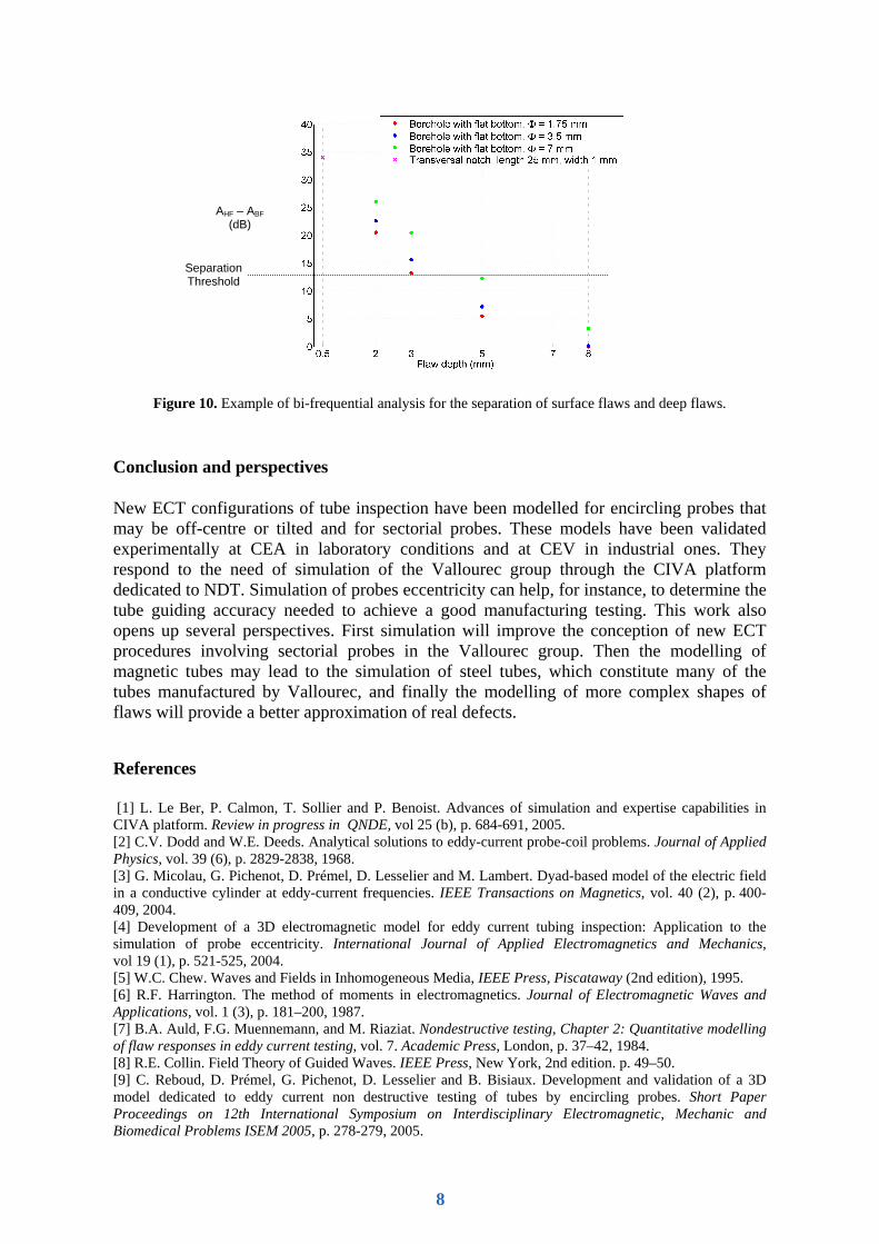
Figure 10. Example of bi-frequential analysis for the separation of surface flaws and deep flaws.
Conclusion and perspectives
New ECT configurations of tube inspection have been modelled for encircling probes that may be off-centre or tilted and for sectorial probes. These models have been validated experimentally at CEA in laboratory conditions and at CEV in industrial ones. They respond to the need of simulation of the Vallourec group through the CIVA platform dedicated to NDT. Simulation of probes eccentricity can help, for instance, to determine the tube guiding accuracy needed to achieve a good manufacturing testing. This work also opens up several perspectives. First simulation will improve the conception of new ECT procedures involving sectorial probes in the Vallourec group. Then the modelling of magnetic tubes may lead to the simulation of steel tubes, which constitute many of the tubes manufactured by Vallourec, and finally the modelling of more complex shapes of flaws will provide a better approximation of real defects.
References
[1] L. Le Ber, P. Calmon, T. Sollier and P. Benoist. Advances of simulation and expertise capabilities in CIVA platform. Review in progress in QNDE, vol 25 (b), p. 684-691, 2005. [2] C.V. Dodd and W.E. Deeds. Analytical solutions to eddy-current probe-coil problems. Journal of Applied Physics, vol. 39 (6), p. 2829-2838, 1968. [3] G. Micolau, G. Pichenot, D. Prémel, D. Lesselier and M. Lambert. Dyad-based model of the electric field in a conductive cylinder at eddy-current frequencies. IEEE Transactions on Magnetics, vol. 40 (2), p. 400-409, 2004. [4] Development of a 3D electromagnetic model for eddy current tubing inspection: Application to the simulation of probe eccentricity. International Journal of Applied Electromagnetics and Mechanics, vol 19 (1), p. 521-525, 2004. [5] W.C. Chew. Waves and Fields in Inhomogeneous Media, IEEE Press, Piscataway (2nd edition), 1995. [6] R.F. Harrington. The method of moments in electromagnetics. Journal of Electromagnetic Waves and Applications, vol. 1 (3), p. 181–200, 1987. [7] B.A. Auld, F.G. Muennemann, and M. Riaziat. Nondestructive testing, Chapter 2: Quantitative modelling of flaw responses in eddy current testing, vol. 7. Academic Press, London, p. 37–42, 1984. [8] R.E. Collin. Field Theory of Guided Waves. IEEE Press, New York, 2nd edition. p. 49–50. [9] C. Reboud, D. Prémel, G. Pichenot, D. Lesselier and B. Bisiaux. Development and validation of a 3D model dedicated to eddy current non destructive testing of tubes by encircling probes. Short Paper Proceedings on 12th International Symposium on Interdisciplinary Electromagnetic, Mechanic and Biomedical Problems ISEM 2005, p. 278-279, 2005.
AHF – ABF (dB)
Separation Threshold
8