simulation and optimization of al–fe aerospace alloy ...servidor.demec.ufpr.br/multigrid/artigos...
TRANSCRIPT

1 3
Heat Mass Transfer (2016) 52:1037–1049DOI 10.1007/s00231-015-1619-y
ORIGINAL
Simulation and optimization of Al–Fe aerospace alloy processed by laser surface remelting using geometric Multigrid solver and experimental validation
Moisés Meza Pariona1,2 · Fabiane de Oliveira1 · Viviane Teleginski2 · Siliane Machado2 · Marcio Augusto Villela Pinto3
Received: 14 August 2014 / Accepted: 25 June 2015 / Published online: 10 July 2015 © Springer-Verlag Berlin Heidelberg 2015
1 Introduction
1.1 Laser‑treated surface
The laser surface remelting (LSR) technique has been extensively studied over the last few years, especially aim-ing to enhance surface microhardness and corrosion resist-ance, since LSR produces microstructural modifications resulting from localized heating and extremely high cool-ing rates, this is supported by Pariona et al. [1].
In recent articles published by authors Pariona et al. [1–3], they studied the processes of casting of Al–1.5 wt% Fe alloy and the samples treated by laser surface melting (LSM). As well as, the characterization of laser-treated layer using different techniques was performed, among the techniques that they used were: optical microscopy, SEM, atomic force microscopy, low-angle X-ray diffraction and microhardness. Finally, the characterization of LSM layer and untreated was done by different techniques of corro-sion. The following are some of the results are described: An homogenous microstructure was verified as a result of rapid solidification; the LSR technique was successfully established to improve the surface properties of Al–1.5 wt% Fe alloys in relation to the substrate alloy; metasta-ble phases in the samples treated by LSM were identified; LSM surface behaved more chemically stable phase in rela-tion to the untreated sample, i.e. improved passive/oxide film after LSR treatment, which could serve as an effec-tive barrier against corrosion attack in aggressive sulfuric acidic environments; in the cyclic polarization curves of the untreated sample it was observed greater area of hyster-esis loop i.e. higher susceptibility to corrosion than for the laser-treated sample; and LSR process indeed has an influ-ence on surface film modification, which results in higher corrosion resistance.
Abstract Al–1.5 wt% Fe alloy was irradiate by Yb-fiber laser beam using the laser surface remelting (LSR) tech-nique, generating weld fillets that covered the whole sur-face of the sample. The laser-treatment showed to be an efficient technology for corrosion resistance improvements. In this study, the finite element method was used to simu-late the solidification processes by LSR technique. The method Multigrid was employed in order to reduce the CPU time, which is important to the viability for industrial applications. Multigrid method is a technique very promis-ing of optimization that reduced drastically the CPU time. The result was highly satisfactory, because the CPU time has fallen dramatically in comparison when it was not used Multigrid method. To validate the result of numerical simu-lation with the experimental result was done the micro-structural characterization of laser-treated layer by the opti-cal microscopy and SEM techniques and however, that both results showing be consistent.
* Moisés Meza Pariona [email protected]
Fabiane de Oliveira [email protected]
Marcio Augusto Villela Pinto [email protected]
1 Department of Mathematic and Statistic, State University of Ponta Grossa (UEPG), Ponta Grossa, PR, Brazil
2 Graduate Program in Engineering and Materials Science, State University of Ponta Grossa (UEPG), Ponta Grossa, PR, Brazil
3 Department of Mechanical Engineering, Federal University of Paraná (UFPR), Curitiba, PR, Brazil

1038 Heat Mass Transfer (2016) 52:1037–1049
1 3
1.2 Mathematical model at laser‑treated
The authors Mikazaki and Giedt [4] studied the tempera-ture distribution around and the heat flow from a cylinder moving through an infinite plate, according to the analyti-cal treatment of partial differential equation. These authors were pioneers, thus, by first time this study was applied to electron beam welding, to study heat flux distributions around an elliptical cylinder moving through an infinite plate, also proposed these authors electron beam weld-ing full penetration model and their studies were com-pared with experimental results, being the comparison was satisfactory.
According to Liu et al. [5], the shaped high power laser beam was employed to simulate the thermal loading on large engine parts like pistons and cylinder heads. Experi-mental and numerical simulation methods were used to study the transient temperature field and helped to the anal-ysis of the thermal fatigue on pistons further, which showed to be competent in the thermal fatigue tests of workpieces with complex configuration.
Other authors like Cho et al. [6] have contributed recently on this subject. They affirmed that one of the goals of laser welding research is to determine optimal conditions by analyzing the effects of the welding conditions from the perspective of the process, metallurgy and mechanics. In welding simulations, it is important to formulate reliable models based on actual welding phenomena. However, practical welding involves complex multiple simultaneous physical phenomena, such as heat transfer, diffusion and electromagnetism, as well as solid, liquid, gas and plasma phases. Thus, many simplifying assumptions are adopted to study physical phenomena separately (Bessroura et al. [7]; Bertelli et al. [8]; Abderrazak et al. [9]). The mathemati-cal models that appear in these problems, in general, do not present analytical solutions. The numerical method was used to turn the continuous model into a discrete model.
A 3D Cartesian coordinate system was set on the work-piece, being the x-axis along the moving welding direction with v speed, y-axis along the width, z-axis along the thick-ness direction, and the origin located on the workpiece sur-face. The transient heat conduction equation, which it was proposed by Yilbas et al. [10] and it is written as
where x, y and z are the vertical, depth and horizontal coor-dinates, respectively, ρ is the density, cp is the specific heat, k the thermal conductivity, rf the surface reflectivity, Io is the laser peak intensity, δ is the absorption depth, t is time,
(1)
ρ∂(CpT)
∂t=
∂
∂x
(
k∂T
∂x
)
+∂
∂y
(
k∂T
∂y
)
+∂
∂z
(
k∂T
∂z
)
+ (1− rf )I0 exp
(
−x2 + y2
a2
)
exp (−δz)
and a is a parameter that determines the laser application form assumed as Gaussian (Gaussian parameter).
1.3 Multigrid methods
To reduce the discretization error in these problems very refined meshes are necessary, which generates large sys-tems of equations. The resolution of these systems through direct or iterative methods requests a large amount of pro-cessing time by the Central Processing Unit (CPU). The convergence rate, which is high at the beginning of the iter-ative process, decreases slightly by increasing the number of iterations, study conducted according to various authors, Briggs et al. [11] and Wesseling [12].
Nowadays, Multigrid method (MG), proposed origi-nally by Fedorenko [13], is one of the most used numerical methods in the solution of systems of equations. Accord-ing to Briggs et al. [11] this method consists on the trans-ference of information among a refined grid, in which the numerical solution is desired, and coarse auxiliary grids, where numerical smoothers (numerical iterative methods to solve systems of equations, called here as solvers) are more efficient. The transference of information between two meshes is done by operators: restriction (from a finer to a coarser grid) and prolongation (from a coarser to a finer grid), following a predetermined sequence of meshes. The methods to solve system of equations in a unique mesh are called Singlegrid (SG).
Brandt [14] and Trottenberg et al. [15] investigated several parameters which can be modified in Multigrid method, such as the solver used, the sequence in which each grid is employed defined as Multigrid cycles (V-cycle, W-cycle, F-cycle and others) and the restriction and the prolongation operators. According to the problem’s fea-tures, the type of information that is transferred among the grids defines Multigrid scheme: the Correction Scheme (CS), in which only the residual is transferred to the coarser grids; or the Full Approximation Scheme (FAS), in which both the residual and the solution are transferred to the coarser grids.
According to Trottenberg et al. [15], studies about Mul-tigrid methods show that the choices of parameters (alge-braic or geometric Multigrid, the coarse mesh structure, solver, inner iterations in each mesh, cycles, restriction and prolongation operators, coarsening rate and others) can have a strong influence in the efficiency of the algo-rithm. There are no general rules in the choice of these parameters, however certain values can be recommended for certain situations. The convergence rate depends on the parameters choices. A simple modification in the algorithm can result in a significant reduction of the CPU time, which justifies the importance of studying the several parameters of Multigrid method.

1039Heat Mass Transfer (2016) 52:1037–1049
1 3
Meanwhile, the Local Fourier Analysis (LFA) is the main quantitative analysis in order to study the convergence of Multigrid methods and to develop new efficient Multigrid algorithms. This analysis is based on the idea that the error can be expressed as linear combination of the so called Fou-rier modes. Non-Fourier version can be seen in more details in Karniadakis [16] and Hussaini and Zang [17].
The purpose of this work is to verify the effect of Mul-tigrid method on the CPU time for the resolution of the heat transfer model, based on the Finite Element Method (FEM), in order to simulate the laser surface remelting of the Al–1.5 wt% Fe alloy. To accelerate the convergence of Singlegrid methods, Multigrid method (MG) was employed in order to reduce the CPU time. In this study we analyzed the influence of different geometric Multigrid parameters on the CPU time in the numerical simulation problem. Further-more, to validate the result of numerical simulation with the experimental result was necessary to perform an analysis of the microstructural characterization of laser-treated layer by the techniques of optical microscopy and SEM.
2 Materials, methods and aspects of the numerical simulation
2.1 Experimental characterization
2.1.1 Preparation of samples
The casting assembly used in solidification experiments consists of water-cooled mold with heat being extracted only from the bottom. It promotes a vertical upward direc-tional solidification and this directional solidification appa-ratus was used to obtain an Al–1.5 wt% Fe alloy cylin-drical casting, with 60 mm diameter and 100 mm length. This alloy was prepared with pure raw materials. Next, 8 mm-wide pieces were cut, polished and sandblasted to reduce their surface reflectance and increase their absorb-ance for the subsequent laser treatment. The laser surface treatment was performed with a 2 kW Yb-fiber laser (IPG YLR-2000S). The laser beam was focused by a 160 mm lens on the sample surface, while the laser wavelength was λ = 1.06 µm and the its intensity of the initial moment was I(0) = 1.81 × 10⁹ W m−2. The other laser parameters were: a power density of 4.8 × 10⁵ W cm−2 with multi-phase dis-tribution of energy with an approximately Gaussian profile, and a scan speed of 40 mm s−1. For this experiment, the sample was positioned 3 mm above the laser focus (out-focusing), using a laser beam diameter of about 600 µm. Experimental works, such as Pariona et al. [1–3] found that the average distance between laser filets was 300 µm and an overlapping of weld filets of about 50 %. This laser treat-ment without an assisting gas jet was applied to augment
the production of metal oxides on the laser-treated surface and to promote the formation of a passive oxide layer in contact with the environment.
2.1.2 Characterization techniques
For the metallographic characterization (morphological study of the material’s structure) of the cross section, small samples were cut and sanded with 600, 800, 1200 grit SiC sand paper, and polished with colloidal silica in a semi-automatic polishing machine (AROTEC Ind. e Com., Bra-zil). Micrographs were recorded by an optical microscopy (OM, Olympus-BX51) and by a scanning electron micros-copy (SEM, Shimadzu SSX-550 microscope).
2.2 Numerical simulation
2.2.1 Numerical simulation by FEM technique
The simulations were carried out with Comsol Multiphys-ics software, version 4.2, in a microcomputer with Intel™
Fig. 1 Schematic view of the laser welding simulation (adapted from Cho et al. [6])
Fig. 2 A 3D computational view of the temperature distribution, including isotherms, for the laser-melted zone, where the initial and boundary conditions are indicated (Adapted from Bag and De [18])
1040 Heat Mass Transfer (2016) 52:1037–1049
1 3
i7 2.8 GHz processor with 12 GB RAM and Linux opera-tional system. For the simulation procedure a schematic view of the geometry was adopted, as shown in Fig. 1.
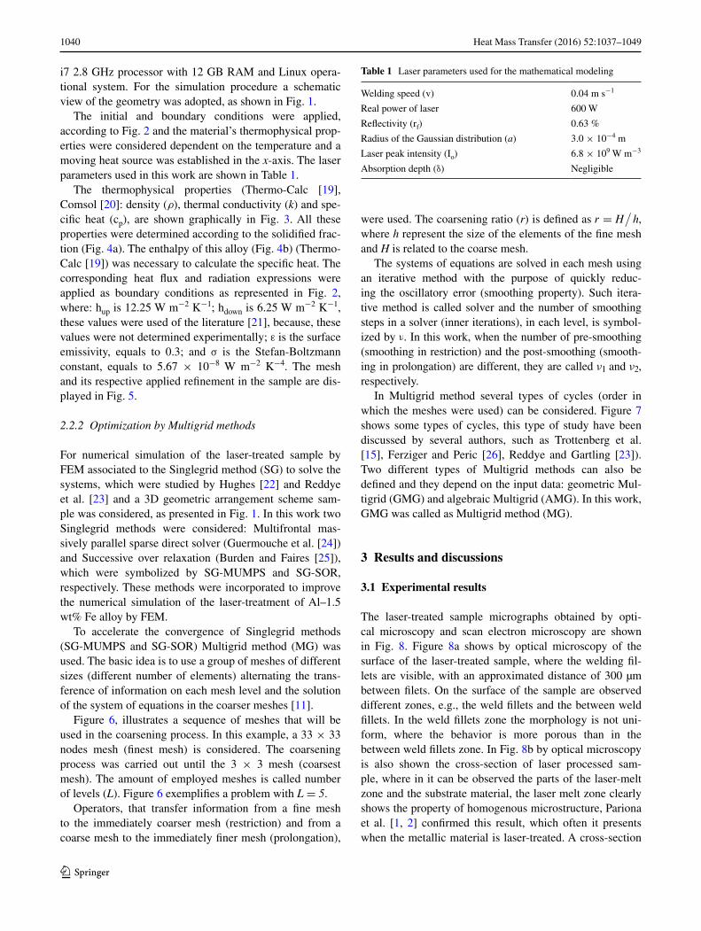
The initial and boundary conditions were applied, according to Fig. 2 and the material’s thermophysical prop-erties were considered dependent on the temperature and a moving heat source was established in the x-axis. The laser parameters used in this work are shown in Table 1.
The thermophysical properties (Thermo-Calc [19], Comsol [20]: density (ρ), thermal conductivity (k) and spe-cific heat (cp), are shown graphically in Fig. 3. All these properties were determined according to the solidified frac-tion (Fig. 4a). The enthalpy of this alloy (Fig. 4b) (Thermo-Calc [19]) was necessary to calculate the specific heat. The corresponding heat flux and radiation expressions were applied as boundary conditions as represented in Fig. 2, where: hup is 12.25 W m−2 K−1; hdown is 6.25 W m−2 K−1, these values were used of the literature [21], because, these values were not determined experimentally; ε is the surface emissivity, equals to 0.3; and σ is the Stefan-Boltzmann constant, equals to 5.67 × 10⁻⁸ W m−2 K−4. The mesh and its respective applied refinement in the sample are dis-played in Fig. 5.
2.2.2 Optimization by Multigrid methods
For numerical simulation of the laser-treated sample by FEM associated to the Singlegrid method (SG) to solve the systems, which were studied by Hughes [22] and Reddye et al. [23] and a 3D geometric arrangement scheme sam-ple was considered, as presented in Fig. 1. In this work two Singlegrid methods were considered: Multifrontal mas-sively parallel sparse direct solver (Guermouche et al. [24]) and Successive over relaxation (Burden and Faires [25]), which were symbolized by SG-MUMPS and SG-SOR, respectively. These methods were incorporated to improve the numerical simulation of the laser-treatment of Al–1.5 wt% Fe alloy by FEM.
To accelerate the convergence of Singlegrid methods (SG-MUMPS and SG-SOR) Multigrid method (MG) was used. The basic idea is to use a group of meshes of different sizes (different number of elements) alternating the trans-ference of information on each mesh level and the solution of the system of equations in the coarser meshes [11].
Figure 6, illustrates a sequence of meshes that will be used in the coarsening process. In this example, a 33 × 33 nodes mesh (finest mesh) is considered. The coarsening process was carried out until the 3 × 3 mesh (coarsest mesh). The amount of employed meshes is called number of levels (L). Figure 6 exemplifies a problem with L = 5.
Operators, that transfer information from a fine mesh to the immediately coarser mesh (restriction) and from a coarse mesh to the immediately finer mesh (prolongation),
were used. The coarsening ratio (r) is defined as r = H/
h, where h represent the size of the elements of the fine mesh and H is related to the coarse mesh.
The systems of equations are solved in each mesh using an iterative method with the purpose of quickly reduc-ing the oscillatory error (smoothing property). Such itera-tive method is called solver and the number of smoothing steps in a solver (inner iterations), in each level, is symbol-ized by ν. In this work, when the number of pre-smoothing (smoothing in restriction) and the post-smoothing (smooth-ing in prolongation) are different, they are called ν1 and ν2, respectively.
In Multigrid method several types of cycles (order in which the meshes were used) can be considered. Figure 7 shows some types of cycles, this type of study have been discussed by several authors, such as Trottenberg et al. [15], Ferziger and Peric [26], Reddye and Gartling [23]). Two different types of Multigrid methods can also be defined and they depend on the input data: geometric Mul-tigrid (GMG) and algebraic Multigrid (AMG). In this work, GMG was called as Multigrid method (MG).
3 Results and discussions
3.1 Experimental results
The laser-treated sample micrographs obtained by opti-cal microscopy and scan electron microscopy are shown in Fig. 8. Figure 8a shows by optical microscopy of the surface of the laser-treated sample, where the welding fil-lets are visible, with an approximated distance of 300 µm between filets. On the surface of the sample are observed different zones, e.g., the weld fillets and the between weld fillets. In the weld fillets zone the morphology is not uni-form, where the behavior is more porous than in the between weld fillets zone. In Fig. 8b by optical microscopy is also shown the cross-section of laser processed sam-ple, where in it can be observed the parts of the laser-melt zone and the substrate material, the laser melt zone clearly shows the property of homogenous microstructure, Pariona et al. [1, 2] confirmed this result, which often it presents when the metallic material is laser-treated. A cross-section
Table 1 Laser parameters used for the mathematical modeling
Welding speed (v) 0.04 m s−1
Real power of laser 600 W
Reflectivity (rf) 0.63 %
Radius of the Gaussian distribution (a) 3.0 × 10⁻⁴ m
Laser peak intensity (Io) 6.8 × 10⁹ W m−3
Absorption depth (δ) Negligible

1041Heat Mass Transfer (2016) 52:1037–1049
1 3
image of the laser-treated samples by scan electron micros-copy is shown in Fig. 8c, where a homogenous microstruc-ture can be seen more clearly, also in this microstructure are observed the laser melt zone and the substrate material, in the laser-melt zone are observed many nano porosities. In a previous article (Pariona et al. [2]), the characterization
of this treated layer was performed and simple metals and metastable intermetallic phases were identified by these authors; the presence of microporosity was also identified, being the largest concentration found on the weld filets. Furthermore, the effect of the laser treatment on the corro-sion resistance of LSR-treated and untreated alloy samples
Fig. 3 Thermophysical properties of Al–1.5 wt% Fe alloy: a specific heat Cp, b thermal conductivity k, and c density ρ (Thermo-Calc software [19], Comsol software [21])
Fig. 4 For the Al–1.5 wt% Fe alloy: a solidified fraction and b enthalpy (Thermo-Calc software [19])
Fig. 5 The mesh and its refine-ment used in this work: a tridi-mensional view, b magnification of details and c a top view

1042 Heat Mass Transfer (2016) 52:1037–1049
1 3
in sulfuric acid (H2SO4) 0.1 M at 25 °C was studied by Pariona et al. [2]. For a comparative characterization, the chemically corroded samples were tested using the open circuit potential (OCP), micro and macropolarization tech-niques. This treatment increased the corrosion resistance 14-fold when compared to the base material of Al–1.5 wt% Fe alloy [2]. The laser treatment on the metal structure pro-duced a chemically and structurally homogenous layer with a fine-grained structure, as can be seen in Fig. 8b, c. These results are coherent with other studies (Pei and Hosson [27], Man et al. [28]) related to investigations of the laser-treated of the Al alloy.
3.2 Numerical results
The FEM simulation was performed based at the condi-tions of the contour shown in Fig. 2, the mesh was based in Fig. 5 and the thermal physics properties used is shown in Fig. 3, where the laser beam was moved from left to right, at a sweep speed of 40 mm/s. As well, the equation gov-erning the transient heat transfer phenomenon is given by Eq. 1. To display the depth of the laser melted zone (LMZ), the condition of symmetry was applied on the y axis.
In Fig. 9a can noted that the isotherms at four different times are not uniformly distributed. In the region located in front of the LMZ, the isotherms are scattered, possibly due to heat energy accumulated through diffusion. On the other hand, in the region situated behind the LMZ presents the lowest scattering of isotherms, this is due to the rap-idly cooling which occurs in this region occurs. Yilbas et al. [10] in their research, confirmed that the heat ahead of the LMZ is transferred by conduction, led by a higher thermal gradient. Therefore, the beam is applied on a highly local-ized area, while the remainder of the material adjacent to the weld fillet is at ambient temperature. Due to this char-acteristic of the LSR-treated surface, high cooling rates are generated during solidification, which have been studied by Pariona et al. [1] and Su et al. [29]. However in Fig. 9b for the time 0.15 s can be observed with more detail the isotherms, at this figure was highlighted a temperature of 933 K which is near of the eutectic temperature of this sys-tem that is 927 K. Therefore for this temperature the liquid phase of Al–Fe turns in Al13Fe4 for cooling in equilibrium.
To optimize the processing time of the simulation was applied Singlegrid method (SG). As a result of this study, Table 2 shows the CPU time (measured in seconds) obtained by the use of SG-MUMPS and SG-SOR methods, for the mesh of Fig. 5. According to the results, it can be verified that SG-SOR is faster than SG-MUMPS. However, Fig. 6 Process of mesh coarsening and generation
Fig. 7 Diagrams of MG cycles: a V-cycle, b F-cycle, c sawtooth and d W-cycle

1043Heat Mass Transfer (2016) 52:1037–1049
1 3
the SG-MUMPS is the standard method of Comsol Mul-tiphysics software.
With the purpose of analyze the influence of different geometric Multigrid parameters on the CPU time in the numerical simulation problem; the process of optimization by Multigrid method was applied. Process of optimization is defined here as the minimization process of the CPU time. In this work, CPU time is concerned about the time interval spent for the grids generation (the basis and the auxiliary grids), the appliance of the initial guess, the coef-ficients evaluation and the solution of the system of linear equations until the achievement of the admitted tolerance.
The employed methodology consists on, for a given the parameter of interest, keeping the other ones with fixed val-ues and, by comparison, choosing the set of parameters is the one that showed the best performance. In this work the simulations with Multigrid method could be split into five categories: type of cycle; number of grids (L); coarsening ratio (r); inner iterations (ν); and solvers. Other methods have been used for comparison, for example: the direct method SG-MUMPS and the iterative method SG-SOR.
As before, like as for the Singlegrid case, the simula-tions were carried out with Comsol Multiphysics soft-ware, however, now with the use of the geometric Multi-grid. The standard parameters of geometric Multigrid used were: solver SOR; one inner iteration in the solver (ν = 1); V-cycle Multigrid; and standard mesh coarsening ratio
(r = 2). Details of parameters of Multigrid method can be found in Trottenberg et al. [15].
For the simulations FEM and triangular grids for mesh were used. For this purpose, four different meshes were considered, with 39,447; 359,719, 987,007 and 2554,531 number of finite element mesh (E). The mesh refinement was focused around the laser source, where the main phe-nomena of heat affected zone and melting occur.
The most representative results related to the five cate-gories of numerical simulations with Multigrid method are presented below.
3.2.1 Types of cycles
The focus of this subsection is the analysis of the type of cycle which provides the minimum CPU time for a given set of parameters. Some authors like Manzano [30] and Chishlom [31] analyzed the type of cycles in Multigrid method and verified that, in general, a W-cycle gives the best results with respect to CPU time.
In order to reduce the number of numerical simulations, all dependent variables for the CPU time minimization and other standard parameters were fixed. Figure 10 shows the comparison among the V, W and F cycles, because, there is a small improvement of the CPU time on the W-cycle when compared with V and F cycles, consequently this result agrees with the analysis done by the authors Manzano
Fig. 8 Microstructural observation in the treated surface and in the cross-section of laser processed sample: a optical microscopy of the treated surface, b optical microscopy in the cross-section, c SEM in the cross-section

1044 Heat Mass Transfer (2016) 52:1037–1049
1 3
[30] and Chishlom [31]. Also on the other hand, the author Chisholm [31] studied the geometric Multigrid for the approximately-Factored implicit Navier–Stokes solver for
airfoils and verified that, he has demonstrated in general, a W-cycle gives the fastest results.
Fig. 9 Numerical simulation during the solidification, showing the pattern of the distribution of the isotherms formed by the LSR treatment: a Distribution of the isotherms in mode transient in different instants of time and b magnified view of the LMZ for the instant of 0.15 s

1045Heat Mass Transfer (2016) 52:1037–1049
1 3
As well, due to the result of Fig. 10 and by studies car-ried out by the authors that were previously mentioned, the use the W-cycle in this work was adopted.
3.2.2 Number of levels
The study of this subsection is the analysis of the num-ber of levels which provides the minimum CPU time for a given set of parameters. Some authors like Suero et al. [32], Oliveira et al. [33], Pinto [34] and Rabi and De Lemos [35] also analyzed the number of levels for problems involving Multigrid method. Figure 11 shows the comparison among the problems with number levels among L = 1 (Singlegrid) and L = 15. It was verified that, for the data tested, with the increasing of the number of finite element mesh (E), the optimum number of levels is approximated L = 2, there-fore, the CPU time was less. Note that, in this case, the W-cycle with two levels is reduced to the V-cycle.
3.2.3 Coarsening ratio
On the other hand was also investigated the optimum number of coarsening ratio, which provides the minimum CPU time for a given set of components. Pinto [34] also analyzed the coarsening ratio for problems of heat transfer. Figure 12 shows the influence of the coarsening ratio on the CPU time. As the size of the problem increases, it becomes
more evident that r = 4 is the most efficient coarsening ratio. This result corroborates the Stüben [36] and Moro [37] results.
Stüben [36] developed a study with r = 2 and r = 4 for unstructured meshes for various two and three-dimen-sional, linear and nonlinear problems of heat transfer, flow and electromagnetism. In his work, he concluded that r = 4 is efficient for anisotropic problems (anisotropy due to the highly stretched meshes). Multigrid method in highly ani-sotropic meshes was also studied by Oliveira et al. [33]. Moro [37] worked with r = 2 and r = 4 in structured meshes for a two-dimensional diffusion problem with source term and verified that r = 4 was faster than r = 2 for the problem under study.
Table 2 CPU time for the Singlegrid methods (SG)
Solver CPU time (s)
SG-MUMPS 7846
SG-SOR 376
Fig. 10 CPU time versus number of elements
Fig. 11 CPU time versus number of levels
Fig. 12 CPU time versus coarsening ratio

1046 Heat Mass Transfer (2016) 52:1037–1049
1 3
3.2.4 Inner iterations
In addition, the optimal number of inner iterations (smooth-ing steps) was studied, which provides the minimum CPU time for a given set of components. Oliveira et al. [33], Gaspar et al. [38] and Rabi and De Lemos [35] also ana-lyzed the optimum number of inner iterations for several problems.
Figure 13 shows the influence of the inner iterations (ν) on the CPU time. It was observed that the minimum CPU time was obtained for ν = ν1 = ν2 = 1, where ν1 and ν2 are the number of pre and post-smoothing, respectively. To study the influence of the size of the linear system of equations, three different values of E (which correspond to three performed discretizations) were used. From this study, it was verified that a small variation in the number of inner iterations increases drastically the CPU time. This result was corroborated by Suero et al. [32] and Gaspar et al. [38]. However, it must be noticed that both groups of authors studied only the Laplace equation. Suero et al. [32] employed the AMG method and Gaspar et al. [38] employed the GMG one.
Another type of tests was also employed, in which the number of inner iterations in the restriction (ν1) can dif-fer from the number of inner iterations in the prolonga-tion (ν2). For the tests, ν1 and ν2 could vary from 0 to 2. It was observed that the minimum CPU time was obtained with ν1 = 1 and ν2 = 0. In literature, this case receives the special name of sawtooth cycle. In this work the sawtooth cycle was applied on the W-cycle.
3.2.5 Comparison between Singlegrid and Multigrid
Hereafter, a comparative study of the performance of the Singlegrid (SG) and Multigrid (MG) methods was
performed. The performance of the direct solver MUMPS (SG-MUMPS) and the iterative solvers SOR without Mul-tigrid (SG-SOR), SOR with standard Comsol’s Multigrid parameters (SMG-SOR) and SOR with optimizes Multi-grid parameters (OMG-SOR) were analyzed. Initially the problem was solved with SG-MUMPS and to compare the methods the speed-up was used.
The speed-up of “algorithm A” in relation to “algorithm B” is a measure used to determine the increase of speed obtained during the execution of a program (tCPU) using an algorithm “A” in relation to his execution using an algo-rithm “B” (Galante [39]). The speed-up is given by the equation:
Table 3 shows the speed-up for some algorithms. The smallest CPU time was obtained with OMG-SOR. In this study it was verified that OMG-SOR is about 123 times faster than the algorithm SG-MUMPS (standard algorithm of Comsol Multiphysics), which is the used algorithm to simulate the laser surface remelting of the Al–1.5 wt% Fe alloy.
An analysis of relaxations parameters (w) for the solver MG-SOR was also carried out: the relaxation parame-ter 0 < w < 2 (under and over relaxation) was tested. In a particular case, when w = 1 the SOR method reduces to Gauss–Seidel [25]. According to this analysis, it was veri-fied that the relaxation parameter does not affect signifi-cantly the CPU time, therefore the value of w = 1 (Gauss–Seidel method) was chosen. Table 4 shows the optimum parameters of Multigrid method obtained in this work.
Through the use of Multigrid method an appreciated reduction in the CPU time was observed. Therefore accord-ing to this result was allowed to perform a mesh finer in the geometry in this work, thereby reducing the error tolerance and getting a better precision in the final result.
3.3 An experimental checking
Different analyses of 3D heat transfer by the Finite Element Method (FEM) were conducted in this work, optimized by Multigrid methods. The validation of numerical results was
(2)S =tCPU (algorithmA)
tCPU (algorithmB)
Fig. 13 CPU time versus inner iterations
Table 3 Speed-up (S) of algorithm A in relation to algorithm B
Algorithm A Algorithm B S
SG-MUMPS SG-SOR 20.87
SG-SOR SMG-SOR 2.46
SG-MUMPS SMG-SOR 51.28
SMG-SOR OMG-SOR 2.39
SG-MUMPS OMG-SOR 122.59

1047Heat Mass Transfer (2016) 52:1037–1049
1 3
done by the comparison the experimental results of laser-treated sample.
Figure 14 shows the comparison between the experi-mental result (SEM micrography) and the numerical sim-ulation, where the thermal distributions are indicated by isotherms in the molten pool and as well as in the heat affected zone. The alignment of the figures is different due to the thermal stresses involved in the treated region, in the present study has not considered this phenomenon.
In the micrograph presented in Fig. 14a, a protuberant is observed on the top surface of the laser welding fillet. Ber-telli et al. [8] affirmed that this a protuberant was observed when the scanning speed of the laser beam is smaller than 0.03 m s−1. Meanwhile, Teleginski et al. [40] observed that the thermal stress originated from the laser treatment gener-ates strain and deformation on the material surface, due to the sudden heating and melting processes of the laser irra-diated region. In this case, only the heat transfer region was considered for the simulations, and therefore Fig. 14b was positioned according to the height of the molten pool. The depth of the molten pool was about 210 µm for 927 Kel-vin. According to the Al–Fe phase diagram (Pariona et al. [1]), the eutectic temperature of this system is 927 K, there-fore for this temperature the liquid phase of Al–Fe turns in Al13Fe4 for cooling in equilibrium.
4 Conclusions
In the study of the microstructure of the laser-treated sam-ple, on the treated surface were observed different zones of morphologies, for example, on the weld-fillets and between weld-fillets. In the cross-section was observed the cast zone with homogeneous behavior of microstructure and with the presence of many nano porosities. This characteristic of microstructure of the laser-treated sample greatly improves the resistance to corrosion as was shown in the literature.
A transient three dimensional heat transfer problem of the laser remelting process was performed by a numeri-cal simulation with the use of the Finite Element Method (FEM), which allowed the prediction of the temperature distributions in the weld fillet. The CPU time was reduced through the use of Multigrid method (MG) to solve that problem, emphasizing the simulation with the optimum Multigrid (OMG-SOR) is about 122 times faster than the simulation with the MUMPS method (SG-MUMPS). Com-paring all numerical studies, the minimum CPU time was obtained with MG and the parameters that have contrib-uted in the optimization, among them were, the number of levels (L = 2); the inner iteration in the restriction (ν1 = 1) and the inner iteration in the prolongation (ν2 = 0); SOR solver; and the coarsening ratio equals to 4 (r = 4).
Multigrid method is a technique very promising of opti-mization that reduced drastically the CPU time. Because, currently in applied sciences, e.g., in problems of type hybrids within the engineering, when they are simulated which causes long times of CPU. Through the employment of Multigrid technique, the cost of the process of CPU can be very lucrative. For example, in this case applied to laser remelting, a transient problem in 3D with thermophysi-cal property variables was applied Multigrid technique for simulated, since the execution time fall of approximately
Table 4 Optimum parameters of Multigrid method
Parameters Optimum
Type of cycle W
Number of levels 2
Coarsening ratio 4
Solver Gauss–Seidel
Inner iteration ν1 = 1 and ν2 = 0
Fig. 14 Comparison between the experimental sample and the numerical simulation, both in the cross section view, where: a SEM micrograph and b simulation result

1048 Heat Mass Transfer (2016) 52:1037–1049
1 3
6 h to 20 min, which represents the application of this tech-nique very positive. In this study, the experimental result of the microstructural characterization was validated with the result of numerical simulation optimized by the tech-nique of Multigrid method, being that the validation was consistent.
Acknowledgments The authors would like to acknowledge the financial support of the Brazilian research funding agencies: CNPq (Conselho Nacional de Desenvolvimento Científico e Tecnológico, Brazil), FA (Fundação Araucária, Paraná, Brazil) and Dedalo (Devel-opment Laboratory of Lasers and Optics Applications) of CTA-IEAv, São José dos Campos, São Paulo, Brazil. The authors would also thank Luciano K. Araki for reviewing the text and for their valuable comments.
References
1. Pariona MM, Teleginski V, Santos K, Machado S, Zara AJ, Zurba NK, Riva R (2012) Yb-fiber laser beam effects on the sur-face modification of Al–Fe aerospace alloy obtaining weld filet structures, low fine porosity and corrosion resistance. Surf Coat Technol 206:2293–2301. doi:10.1016/j.surfcoat.2011.10.007
2. Pariona MM, Teleginski V, Santos K, Santos ELR, Lima AAOC, Riva R (2012) AFM study of the effects of laser surface remelt-ing on the morphology of Al–Fe aerospace alloys. Mater Charact 74:64–76. doi:10.1016/j.matchar.2012.08.011
3. Pariona MM, Teleginski V, Santos K, Lima AAOC, Zara AJ, Micene KT, Riva R (2013) Influence of laser surface treated on the characterization and corrosion behavior of Al–Fe aerospace alloys. Appl Surf Sci 276:76–85. doi:10.1016/j.apsusc.2013.03.025
4. Miyazaki T, Giedt WH (1982) Heat transfer from an elliptical cylinder moving through an infinite plate applied to electron beam welding. Int J Heat Mass Transf 24:807–814
5. Liu X, Pang M, Zhang ZG, Tan JS, Zhu GX, Wang MD (2012) Numerical simulation of stress field for laser thermal load-ing on piston. Opt Laser Technol 44:1636–1640. doi:10.1016/j.optlastec.2011.12.045
6. Cho W, Na SJ, Thomy C, Vollertsen F (2012) Numerical simu-lation of molten pool dynamics in high power disk laser weld-ing. J Mater Process Technol 212:262–275. doi:10.1016/j.jmatprotec.2011.09.011
7. Bessroura ABJ, Masseb J, Bouhafsa M, Barrallier L (2010) Finite element simulation of magnesium alloys laser beam weld-ing. J Mater Process Technol 210:1131–1137. doi:10.1016/j.jmatprotec.2010.02.023
8. Bertelli F, Meza ES, Goulart PR, Cheung N, Riva R, Garcia A (2011) Laser remelting of Al–1.5 wt% Fe alloy surfaces: numeri-cal and experimental analyses. Opt Lasers Eng 49:490–497. doi:10.1016/j.optlaseng.2011.01.007
9. Abderrazak K, Kriaa W, Salem WB, Mhiri H, Lepalec G, Autric M (2009) Numerical and experimental studies of molten pool formation during an interaction of a pulse laser (Nd:YAG) with a magnesium alloy. Opt Laser Technol 41:470–480. doi:10.1016/j.optlastec.2008.07.012
10. Yilbas BS, Arif AFM, Karatas C, Raza K (2009) Laser treatment of aluminum surface: analysis of thermal stress field in the irradi-ated region. J Mater Process Technol 209:77–88. doi:10.1016/j.jmatprotec.2008.01.047
11. Briggs WL, Henson VE, Mccormick SF (2000) A Multigrid tuto-rial, 2nd edn. SIAM, Philadelphia
12. Wesseling P (1992) An introduction to Multigrid methods. Wiley, Philadelphia
13. Fedorenko RP (1964) On the speed of convergence of an itera-tion process. USSR Comput Math Math Phys 4:227–235. doi:10.1016/0041-5553(64)90253-8
14. Brandt A (1977) Multi-level adaptive solutions to boundary-value problems. Math Comput 31:333–390. doi:10.1090/S0025-5718-1977-0431719-X
15. Trottenberg U, Oosterlee CA, Schüller A (2001) Multigrid. Aca-demic Press, St Augustin
16. Karniadakis GE (1990) Spectral element-fourier methods for tur-bulent flows, computer methods in applied mechanics and engi-neering. North-Holland 80:367–380
17. Hussaini MY, Zang TA (1987) Spectral methods in fluid dynam-ics. Ann Rev Fluid Mech 19:339–367
18. Bag S, De A (2010) Computational modelling of conduction mode laser welding process. Laser welding. InTech., Open access. doi:10.5772/256
19. THERMO CALC software (2010) Stockholm, Sweden 20. Users Handbook COMSOL Multiphysics. v. 4.2a (2012) 21. COMSOL Release notes 3.3a (2007) Friction stir welding 22. Hughes TJR (2000) The finite element method—linear static and
dynamic finite element analysis. Dover Publications, Mineola 23. Reddye JN, Gartling DK (1994) The finit element method in heat
transfer and fluid dynamics. CRC Press, Boca Raton 24. Guermouche A, Yves J, L’Excellent Utard G (2003) Impact of
reordering on the memory of a multifrontal solver. Parallel Com-put 29:1191–1218. doi:10.1016/S0167-8191(03)00099-1
25. Burden RL, Faires JD (2010) Numerical analysis. Brooks-Cole, 9th edn. Cengage Learning, Australia
26. Ferziger JH, Peric M (2002) Computational methods for fluid dynamics, 3rd edn. Springer, Berlin
27. Pei YY, Hosson JTM (2000) Functionally graded materi-als produced by laser cladding. Acta Mater 48:2617–2624. doi:10.1002/9781118787694.ch19
28. Man HC, Yang YQ, Lee WB (2004) Laser induced reaction syn-thesis of TiC + WC reinforced metal matrix composites coat-ings on Al 6061. Surf Coat Technol 185:74–80. doi:10.1016/j.surfcoat.2003.10.132
29. Su HJ, Zhang J, Ren Q, Deng YF, Liu L, Fu HZ, Soh AK (2013) Laser zone remelting of Al2O3/Er3Al5O12 bulk oxide in situ composite thermal emission ceramics: influence of rapid solidification. Mater Res Bull 48:544–550. doi:10.1016/j.materresbull.2012.11.052
30. Manzano L (1999) Implementation of multigrid for aerodynamic computations on multi-block grids. Dissertation, Department of aerospace science and engineering, University of Toronto
31. Chisholm T (1997) Multigrid acceleration of an approximately-factored algorithm for steady aerodynamic flows. Dissertation, University of Toronto
32. Suero R, Pinto MAV, Marchi CH, Araki LK, Alves AC (2012) Analysis of algebraic Multigrid parameters for two-dimen-sional steady-state heat diffusion equations. Appl Math Model 36:2996–3006. doi:10.1016/j.apm.2011.09.088
33. Oliveira F, Pinto MAV, Marchi CH, Araki LK (2012) Optimized partial semicoarsening Multigrid algorithm for heat diffusion problems and anisotropic grids. Appl Math Model 36:4665–4676. doi:10.1016/j.apm.2011.11.084
34. Pinto MAV (2006) Multigrid method behavior problems in heat transfer. PhD Thesis, UFPR, Curitiba, PR-Brazil
35. Rabi JA, De Lemos MJS (1998) The Effects of Peclet number and cycling strategy on Multigrid numerical solutions of con-vective-advective problems. In: 7th, AIAAIASME international thermics and HT conference, Paper AIAA-98-2584, Albuquer-que, New Mexico, USA

1049Heat Mass Transfer (2016) 52:1037–1049
1 3
36. Stüben K (1999) Algebraic Multigrid (AMG): an introduction with applications. In: GMD-report 70
37. Moro Filho RC (2004) Technical application of multigrid in computational heat transfer, XXV Iberian Latin_American con-gress on computational methods in engineering
38. Gaspar FJ, Gracia JL, Lisbona FJ, Rodrigo C (2009) On geomet-ric Multigrid methods for triangular grids using three-coarsen-ing strategy. Appl Numer Math 59:1693–1708. doi:10.1016/j.apnum.2009.01.003
39. Galante G (2006) Parallel Multigrid methods on structured meshes non-simulation applied problems of computational fluid dynamics na heat transfer. Dissertation UFRGS, Porto Alegre, RS, Brazil
40. Teleginski V, Riva R, Pariona MM (2012) Avaliação do estresse térmico no tratamento de refusão superficial a laser da liga Al–1.5% Fe através da técnica dos elementos finitos. In: 67º Congresso ABM, 2012, Rio de Janeiro. Anais do 67º Congresso Anual da ABM 3518–3527