simulation and implementation of power electronics for ... · phd student eng. delfim pedrosa for...
TRANSCRIPT

Mohamed Tanta
Simulation and Implementation ofPower Electronics for EducationalPurposes - with SEPIC Converter for MPPT
Moh
amed
Tan
taUM
inho
| 2
014
Sim
ulat
ion
and
Impl
emen
tatio
n of
Pow
er E
lect
roni
csfo
r Ed
ucat
iona
l Pur
pose
s - w
ith S
EPIC
Con
vert
er fo
r M
PPT
Universidade do MinhoEscola de Engenharia
December 2014


December 2014
Thesis submitted at the University of Minhofor the degree of Master inIndustrial Electronics and Computer Engineering
Work performed under the supervision ofProfessor João Luiz Afonso
Mohamed Tanta
Simulation and Implementation ofPower Electronics for EducationalPurposes - with SEPIC Converter for MPPT
Universidade do MinhoEscola de Engenharia

DECLARATION
Mohamed Tanta
E-mail address: [email protected] Telephone: 00351-938419012
Number of Identity:
Title of Thesis:
Simulation and Implementation of Power Electronics for Educational
Purposes - with SEPIC Converter for MPPT
Supervisor:
Professor João Luiz Afonso.
Year of completion: 2014
Thesis submitted at the University of Minho for the degree of Master in Industrial
Electronics and Computer Engineering.
University of Minho, ___/___/______
Signature: ________________________________________________

To my family, my friends and all of my relatives.
To my country Syria, for Portugal and Portuguese people.


Simulation and Implementation of Power Electronics for Educational Purposes - with SEPIC Converter for MPPT
Mohamed Tanta – University of Minho v
Acknowledgements
The completion of the work presented here would not have been possible without
the support and the contribution of some people, to whom I send my sincere thanks:
My advisor, Professor João Luiz Afonso for his guidance and persistent help.
Your professional and spiritual support helped me to identify and to understand Power
Electronics. Thank you for your patience, for countless thoughtful long technical
discussions and for your friendly attitude as it has greatly contributed to my professional
and personal growth and made it possible to complete this work.
Special thanks for the professors Júlio Martins and Manuel João Sepúlveda for
their kindness and excellent comments which helped me to correct many parts of this
work.
To my colleagues in the laboratory of GEPE (Group of Energy and Power
Electronics).
Dr. José Gabriel Oliveira Pinto for his guidance about the technical management
which I used throughout this thesis and without his help, this work will not be
completed.
PhD student Eng. Bruno Exposto for his guidance about technical support.
PhD student Eng. Delfim Pedrosa for his guidance in hardware materials that
were used in this project.
Eng. Raul Almeida.
To my friends, research fellows.
Employees Carlos Torres, Joel Almeida and Angela Macedo who, as technical
workshops of the Department of Industrial Electronics.
To all students who took the master's thesis in Power Electronics Laboratory,
respect the environment and provided friendship.
In the end, special thanks for Program of “Global Platform for Syrian Students”
which sponsored by President Jorge Sampaio and other financial institutions.
I am very grateful to Portugal and Portuguese people ......


Simulation and Implementation of Power Electronics for Educational Purposes - with SEPIC Converter for MPPT
Mohamed Tanta – University of Minho
Abstract
Nowadays, the importance and investments in electricity and renewable energy
sources is significantly growing, so that the development and prosperity level of nations
are measured accordingly with the strength and the efficiency of the power sector in the
country.
Every day, the importance of renewable energy sources in the world is increasing
to compensate the growing demand of energy in the future, especially with the global
rise in oil prices and the environmental pollution. Therefore, renewable energy sources,
such as wind, sun, biomass, waves and tides, will be the energy providers for our planet
in the future.
Renewable energy sources are closely linked with power electronics, so that it is
not possible to obtain the required electrical power without using semiconductor
electronic elements, which have the capability to convert electrical power (for example,
rectifiers can convert electrical power from AC to DC and the inverters do exactly the
opposite). These elements give sufficient flexibility to control and convert the voltages
according to our application, and in function of the load needs.
All of the above indicates the importance of power electronics area in the present
time. Therefore, as a part of this project, a tutorial document on power electronics has
been written for students and non-specialists who want to learn power electronics and
know the basics of this area of Electrical Engineering. This document has an organizing
strategy and arrangement in order to facilitate and give motivation for students to study
power electronics, trying to provide, as much as possible, simple explanations and
figures. Every circuit in this document was simulated by using the programs PSIM and
MATLAB, which gives the possibility for students to change the circuit parameters, then
monitoring the new results (with this document is made available a CD with the
simulations models of the circuits). In addition, it contains worked examples with the
most important ideas that must be known for every example. All figures and results of
circuits are drawn to facilitate and clarify the figures as much as possible, using a
plotting program named KST.
As a practical part of this Master thesis work, which also aims to merge renewable
energy sources and power electronics applications, a battery charging system with
MPPT circuit was implemented, to be used with a micro wind turbine, which can be
employed in a boat in the future. This work used a micro wind turbine with a permanent
magnet synchronous generator which converts mechanical energy into electrical energy.

The generator produces AC three-phase voltages that are rectified with an
uncontrolled rectifier, PD3, which is then connected to a DC-DC converter (coupled
inductor SEPIC converter), used here to increase or decrease the DC voltage value. In
the output of the rectifier is used a capacitor to filter the DC voltage. The implemented
control method uses a Maximum Power Point Tracker (MPPT), with perturbation and
observation algorithm. This algorithm is ideal to use with intermittent wind energy
resources. To operate at the optimal power point, the algorithm has to change the duty
cycle of the SEPIC. This control was implemented in a microcontroller ARDUINO
ATMEGA UNO 328P. All the developed system for energy production was simulated
using PSIM program. This allowed to observe the behavior of the system when was
used a passive load (resistive load) and an active load (battery).
Finally, with this work I hope to create benefits to my homeland Syria and to my
second country, Portugal.
Keywords: SEPIC, Power Electronics, Maximum Power Point Tracker
(MPPT), Micro Wind Turbine, Renewable Energy, Education, Simulation,
Implementation, ADC, PWM.
Resumo
Hoje em dia, a importância e o investimento na energia elétrica e em fontes de
energia renováveis tem uma grande preponderância nas nossas vidas. O grau de
prosperidade e o desenvolvimento das nações pode ser aferido através do grau de
importância do setor energético no país.
A cada dia que passa, a importância das fontes de energia renováveis aumenta,
uma vez que existe uma procura cada vez maior de energia, isto tendo em conta o
aumento mundial dos preços de combustível e a poluição ambiental. Tendo em conta
isto, as fontes de energia renováveis, tais como o vento, o sol, a biomassa, as ondas e as
marés, serão os fornecedores de energia para o nosso planeta num futuro próximo.
As fontes de energia renováveis estão intimamente ligadas com a eletrónica de
potência, e não é possível obter a energia elétrica desejada sem usar elementos
eletrónicos semicondutores, os quais têm a capacidade de realizar conversões (por
exemplo os retificados podem converter tensão CA para CC, e os inversores o oposto).
Estes elementos dão flexibilidade suficiente para controlar e converter as tensões
de acordo com a nossa aplicação, e conforme a carga.
Tudo o que é referido acima indica a importância da eletrónica de potência nos
tempos atuais. Desta forma, como parte deste trabalho de Dissertação de Mestrado, foi
escrito um tutorial de eletrónica de potência destinado aos estudantes e aos
não-especialistas que querem aprender eletrónica de potência e perceber as bases desta
área da Engenharia Eletrotécnica. Este documento apresenta uma certa estratégia e
organização facilitadoras e motivadoras para que os alunos venham a estudar eletrónica
de potência, contendo, dentro do possível, explicações e figuras simples. Cada circuito
apresentado neste documento foi simulado usando os softwares PSIM e MATLAB,
sendo oferecida a possibilidade aos estudantes para alterar os parâmetros dos circuitos e
observarem os resultados (o documento é acompanhado de um CD com os modelos de
simulação). Além disto, o documento contém exemplos trabalhados mostrando os
conceitos mais importantes de cada circuito. Todas as figuras e resultados dos circuitos
foram desenhados de forma a facilitar a sua compreensão, utilizando um programa
designado KST.
Como parte prática deste trabalho, e envolvendo a fusão entre a eletrónica de
potência e as aplicações de energias renováveis, foi implementado um circuito
carregador de baterias com circuito MPPT, a ser usado com uma turbina micro-eólica, e
que poderá ser empregado em barcos, no futuro. Neste projeto foi usada uma micro-

turbina com um gerador síncrono de ímanes permanentes que converte a energia
mecânica do vento em energia elétrica. O gerador produz tensões CA que necessitam de
ser retificadas, e para isso é usado um retificador não controlado, PD3, ligado a um
conversor DC-DC (conversor SEPIC com indutância de acoplamento mútuo). O
conversor serve para aumentar ou diminuir a tensão de saída. Além disto, o retificador
tem na sua saída um condensador de forma a filtrar a tensão. O método de controlo
implementado foi um seguidor do ponto de máxima potência (Maximum Power Point
Tracker - MPPT). O algoritmo do MPPT usado foi o da perturbação-observação. Este
algoritmo é o ideal para utilizar com as fontes de energia intermitentes, como é o caso
do vento. Para operar no ponto de máxima potência, o algoritmo tem que mudar
constantemente o duty-cycle do conversor SEPIC. Este controlo foi implementado numa
placa de desenvolvimento ARDUINO ATMEGA UNO 328P. O sistema para produção
de energia desenvolvido foi todo simulado usando o software PSIM. Isto permitiu
observar o comportamento desse sistema quando foi colocada na sua saída uma carga
passiva (carga resistiva) e uma carga ativa (bateria).
Finalmente, com este trabalho, espero poder trazer benefícios ao meu país natal, a
Síria, e ao meu segundo país, Portugal.
Palavras-Chave: SEPIC, Eletrónica de Potência, Rastreador de ponto de
máxima potência (MPPT), Turbina micro-eolica, Energias Renováveis, Educação,
Simulação, Implementação, ADC, PWM.
Simulation and Implementation of Power Electronics for Educational Purposes - with SEPIC Converter for MPPT
Mohamed Tanta – University of Minho xi
List of Contents Introduction ........................................................................................................................ 1 CHAPTER 1
The History of Power Electronics ................................................................................................ 1 1.1.
The Importance and Needing of New Ways to Learn Power Electronics .................................... 2 1.2.
Implementation of Power Electronics Circuits ............................................................................ 3 1.3.
Motivations .................................................................................................................................. 4 1.4.
Objectives and Contributions ....................................................................................................... 4 1.5.
Thesis Organization ..................................................................................................................... 5 1.6.
What Exists for Learning Power Electronics ................................................................... 7 CHAPTER 2
Introduction .................................................................................................................................. 7 2.1.
Electronic Learning Sources ........................................................................................................ 8 2.2. Power Electronics Websites and Interactive Forums ........................................................................... 8 2.2.1.
Video Conferencing and Educational Videos ...................................................................................... 9 2.2.2.
Electronic Books which are Provided with Animated Figures .......................................................... 10 2.2.3.
Special Educational Books Written by the Manufacturer .................................................................. 10 2.2.4.
Social Network Websites which Include a Content of Interactive Groups ........................................ 11 2.2.5.
Traditional Learning Sources ..................................................................................................... 12 2.3. Power Electronics Journals ................................................................................................................ 12 2.3.1.
Traditional Educational Books .......................................................................................................... 13 2.3.2.
Modeling and Simulation Programs........................................................................................... 14 2.4.
Conclusion ................................................................................................................................. 15 2.5.
Theory of Power Electronics Circuits ............................................................................. 17 CHAPTER 3
Introduction ................................................................................................................................ 17 3.1.
Multi-Purpose Power Electronics Circuit .................................................................................. 17 3.2.
Graetz Bridge (H Bridge) ........................................................................................................... 17 3.3. Graetz Bridge Rectifier ...................................................................................................................... 18 3.3.1.
3.3.1.1. Full controlled Greaetz Bridge Rectifier............................................................................................ 18 3.3.1.2. Half Controlled Symmetrical Graetz Bridge Rectifier ....................................................................... 20 3.3.1.3. Half Controlled Asymmetrical Graetz Bridge Rectifier .................................................................... 21
Graetz Bridge (H Bridge) Chopper .................................................................................................... 23 3.3.2.
Graetz Bridge (H Bridge) Inverter ..................................................................................................... 26 3.3.3.
Three Phase PD3 Dual Converter .............................................................................................. 27 3.4.
Three Phase PD3 Cyclo Converter (Frequency Converter) ....................................................... 29 3.5.
Conclusion ................................................................................................................................. 31 3.6.
Simulation of Power Electronic Circuits ........................................................................ 33 CHAPTER 4
Introduction ................................................................................................................................ 33 4.1.
Modeling and Simulation Type .................................................................................................. 33 4.2.
Simulation Feasibilities and Limits ............................................................................................ 34 4.3.
Power Electronics Simulation Programs .................................................................................... 35 4.4. MATLAB Program ............................................................................................................................. 35 4.4.1.
Powersim Program (PSIM) ................................................................................................................ 40 4.4.2.
Conclusion ................................................................................................................................. 45 4.5.
Development and Simulation Results of the MPPT System with SEPIC Converter .. 47 CHAPTER 5
Introduction ................................................................................................................................ 47 5.1.
Wind Power Generator .............................................................................................................. 47 5.2.
Uncontrolled Three-Phase Rectifier Bridge with Condenser ..................................................... 53 5.3.
SEPIC Converter Design ........................................................................................................... 54 5.4. Duty Cycle Values ............................................................................................................................. 55 5.4.1.
Inductors Values ................................................................................................................................ 55 5.4.2.
Capacitors Values .............................................................................................................................. 57 5.4.3.
Selection of Active Components ....................................................................................................... 58 5.4.4.
Control Process .......................................................................................................................... 59 5.5. Generation of PWM Pulses with the Possibility of Changing the Duty Cycle .................................. 61 5.5.1.
Read the Input Voltage / current Values (ADC) ................................................................................ 64 5.5.2.
MOSFET Driving Circuit .......................................................................................................... 65 5.6.
MPPT Control Algorithm .......................................................................................................... 65 5.7.
Simulation Results Using PSIM ................................................................................................. 68 5.8.
Conclusion ................................................................................................................................. 72 5.9.

Experimental Results of the MPPT System with SEPIC Converter ............................ 75 CHAPTER 6
Introduction ................................................................................................................................ 75 6.1.
MOSFET Frequency Response .................................................................................................. 75 6.2.
MPPT Experimental Results ...................................................................................................... 77 6.3. MPPT Experimental Results by Using Passive Load ........................................................................ 78 6.3.1.
MPPT Implementation Results by Using Active Load (Battery) ....................................................... 79 6.3.2.
Comparison between Simulation and Implementation Results .................................................. 82 6.4.
Conclusion ................................................................................................................................. 82 6.5.
Conclusion ......................................................................................................................... 85 CHAPTER 7
Conclusions ................................................................................................................................ 85 7.1.
Suggestions for Future Works .................................................................................................... 86 7.2.

Simulation and Implementation of Power Electronics for Educational Purposes - with SEPIC Converter for MPPT
Mohamed Tanta – University of Minho xiii
List of Figures
Figure 1.1 - Power Electronics structure loop. ............................................................................................. 2
Figure 1.2 -Tesla superconducting magnet – CERN [2]. ............................................................................. 3
Figure 1.3 - Micro wind power application using SEPIC converter. ........................................................... 4
Figure 2.1- Some examples of tutorial power electronics websites. ............................................................ 9
Figure 2.2 - Video conference system [5]. ................................................................................................... 9
Figure 2.3 - Some of books written by the manufacturer [7] [8]. .............................................................. 11
Figure 2.4 – some power electronics journals [9]. ..................................................................................... 13
Figure 3.1 - Graetz bridge feeding points. ................................................................................................. 18
Figure 3.2 - Center tapped transformer with PD2 full controlled bridge. .................................................. 19
Figure 3.3 - PD2 full controlled Graetz rectifier results at . .......................................................... 19
Figure 3.4 - PD2 Symmetrical Half-Controlled Bridge. ............................................................................ 20
Figure 3.5 - Symmetrical Half bridge Results (Inductive load). ................................................................ 20
Figure 3.6 - PD3 Asymmetrical Half-Controlled Bridge. .......................................................................... 22
Figure 3.7 - PD2 Asymmetrical Half-Controlled Bridge Results. ............................................................. 22
Figure 3.8 - Full bridge chopper circuit. .................................................................................................... 23
Figure 3.9 - Full bridge chopper results at K . ................................................................................... 25
Figure 3.10 - work characteristic curves for full bridge chopper. .............................................................. 25
Figure 3.11 - Single phase H bridge Inverter circuit. ................................................................................. 26
Figure 3.12 - Single phase H bridge Inverter results. ................................................................................ 27
Figure 3.13 - PD3 Dual Converter. ............................................................................................................ 28
Figure 3.14 - Relation between firing angles and average output voltage value in Dual converter. .......... 28
Figure 3.15 - PD3 Dual Converter Results , . ............................................................... 29
Figure 3.16 - Driving mechanism for simple half wave step down Cyclo converter. ................................ 30
Figure 3.17 - Three phase to single phase Cyclo converter Results........................................................... 31
Figure 4.1 - Real time simulator in MATLAB [17]. .................................................................................... 34
Figure 4.2 - RLC Power Circuit. ................................................................................................................ 36
Figure 4.3 - The mathematical model for RLC power circuit. ................................................................... 37
Figure 4.4 - Simulation results for a RLC power circuit. ........................................................................... 38
Figure 4.5 - Three phase rectifier bridge. ................................................................................................... 39
Figure 4.6 - Three phase rectifier bridge results by using Simpowersystem library. .................................. 39
Figure 4.7 – Three-phase controlled rectifier bridge model using Simpowersystem library. ..................... 40
Figure 4.8 - PSIM environment [20]. ......................................................................................................... 41
Figure 4.9 - PSIM controllers for driving power electronics switches. ...................................................... 43
Figure 4.10 – Three-phase controlled rectifier bridge model by using PSIM. ........................................... 44
Figure 4.11 – Three-phase controlled rectifier bridge results by using PSIM. ........................................... 44
Figure 5.1 - The ideal power curve of wind turbine [22]. .......................................................................... 48
Figure 5.2 - Power coefficient curve as a function with TSR ( ). ..................................................... 49
Figure 5.3 - Mechanical power – speed characteristics. ............................................................................ 50
Figure 5.4 - SilentWind micro wind turbine [24]. ...................................................................................... 50

List of Figures
Figure 5.5 - Permanent magnet synchronous generator. ............................................................................ 51
Figure 5.6 - SilentWind turbine power curve characteristics [24]. ............................................................. 52
Figure 5.7 - Using two single phase rectifiers to obtain three phase rectifier bridge. ................................ 53
Figure 5.8 - Condenser. ............................................................................................................... 53
Figure 5.9 - SEPIC converter equivalent circuit. ....................................................................................... 54
Figure 5.10 - Coupled inductor with mutual inductance. ........................................................................... 57
Figure 5.11 - Implemented circuit of SEPIC converter. ............................................................................ 59
Figure 5.12 - ATMEGA UNO 328P board [27].......................................................................................... 60
Figure 5.13 - Phase correct PWM / Phase and frequency correct PWM modes [28]. ............................... 61
Figure 5.14 - Fast PWM mode using ATMEGA UNO 328P [28]. ............................................................. 63
Figure 5.15 - Optical isolation between microcontroller and gate to ground circuit.................................. 65
Figure 5.16 - MOSFET driving circuit. ..................................................................................................... 65
Figure 5.17 - MPPT perturbation and observation control method [22]. ................................................... 66
Figure 5.18 - MPPT perturbation and observation flowchart [32]. ............................................................ 67
Figure 5.19 - Equivalent circuit of maximum power transfer theory. ........................................................ 68
Figure 5.20 - Primary simulation model to test MPPT control. ................................................................. 69
Figure 5.21 - MPPT simulation results in case of R RLoad . ................................... 70
Figure 5.22 – Line and phase voltages of synchronous generator – Rectified voltage. ............................. 71
Figure 5.23 - MPPT simulation results in case of 12 V active load. .......................................................... 72
Figure 5.24 - charging current of battery result. .................................................................................... 72
Figure 6.1 - YOKOGAWA digital oscilloscope. ....................................................................................... 76
Figure 6.2 - MOSFET’s response at different PWM frequencies. ............................................................. 77
Figure 6.3 - MPPT implementation results by using passive load. ............................................................ 79
Figure 6.4 - Protection circuit from high charging current. ....................................................................... 80
Figure 6.5 - VRLA GEL Battery that is used in the project. ...................................................................... 80
Figure 6.6 - battery voltage – input voltage of SEPIC - charging current of battery . ................. 81
Figure 6.7 - Input current of SEPIC - charging current of battery . .................................................... 82

Simulation and Implementation of Power Electronics for Educational Purposes - with SEPIC Converter for MPPT
Mohamed Tanta – University of Minho xv
List of Tabels
Table 3.1 - Work mechanism for PD2 Graetz rectifier. ............................................................................. 19
Table 3.2 - Work mechanism for symmetrical PD2 Graetz rectifier. ........................................................ 21
Table 3.3 - Work mechanism for asymmetrical PD2 Graetz rectifier. ....................................................... 23
Table 3.4 - Work mechanism for single phase H bridge inverter. ............................................................. 26
Table 5.1 - Electrical characteristics for micro wind “SilentWind” [ ] ................................................... 51
Table 5.2 - Mechanical characteristics for micro wind “SilentWind” [ ] ............................................... 51
Table 5.3 - Obtained test results in no – load case. .................................................................................... 52
Table 5.4 - Coupled inductor characteristics at 124 KHz frequency. ........................................................ 57
Table 5.5 - Choosing fast PWM mode ....................................................................................................... 63
Table 5.6 - Wind turbine and synchronous generator characteristics in PSIM .......................................... 70


Simulation and Implementation of Power Electronics for Educational Purposes - with SEPIC Converter for MPPT
Mohamed Tanta – University of Minho xvii
List of Abbreviations and Acronyms
PE Power Electronics
ESA European Space Agency
CERN European Council for Nuclear Research
SEPIC Single Ended Primary Inductance Converter
MPPT Maximum Power Point Tracker
PD3 Three-phase rectifier bridge
PD2 Single phase rectifier bridge
HVDC High Voltage Direct Current
SCR Silicon Controlled Rectifier
GTO Gate Turn-Off Thyristor
BJT Bipolar junction Transistor
PWM Pulse Width Modulation
TSR Tip Speed Ratio
EMI Electromagnetic Interference
ICSP In-circuit serial programmer
ADC Analogue to Digital Converter
OTC Optimal Torque Control
P&O Perturbation and Observation
IGBT Insulated Gate Bipolar Transistor
IEEE 1. Institute of Electrical and Electronics Engineers
DSP 2. Digital Signal Processing
PI 3. Proportional Integrator


Simulation and Implementation of Power Electronics for Educational Purposes - with SEPIC Converter for MPPT
Mohamed Tanta – University of Minho xix
Nomenclature
Symbol Meaning Unit
Average output voltage DC voltage – Rectified voltage V
The number of circuit’s branches -
Firing angle of thyristor Degree
Angular frequency Rad/sec
Duty cycle -
Instantaneous value of output voltage V
Electro-motive force V
Frequency, input frequency, output frequency Hz
Resistor
Resistor of Drain-Source junction in turn-on case
Initial speed value m/sec
Final speed value m/sec
Rated speed value m/sec
Radius of turbine blades m
Mechanical torque N.M
Gear ratio between the turbine shaft and the generator rotor shaft -
Pitch angle of the wind turbine Degree
Power coefficient function -
Number of poles pole
Circuit efficiency -
Factor between 20% and 40% -
Rotor swept area m
Air density
Kg m
V Wind speed m/sec

List of Figures
Peak phase value of source voltage V
Source voltage V
Diode voltage dropping V
Reference voltage V
Peak line-to-line back EMF constant V
RMS input voltage V
Inductance H
C Capacitor F
T Period sec
Output DC current A
, Source current A
, Inductor current A
Inductor ripple current A
Current rating for MOSFET A
Wind turbine output power W
Losses power in MOSFET W
Output power of the rectifier W
Input power of SEPIC W

Simulation and Implementation of Power Electronics for Educational Purposes - with SEPIC Converter for MPPT
Mohamed Tanta – University of Minho 1
CHAPTER 1
Introduction
The History of Power Electronics 1.1.
The amazing evolution in lots of technical fields these days was not achieved
without the appearance of electronics and area of electrical engineering at the beginning
of the twentieth century which is a continuously renewable field. Nowadays, the world
depends more and more on renewable energy applications which are closely linked with
Power Electronics (PE) area to convert the type of energy according to the purpose by
using rectifiers, choppers, inverters and frequency converters to achieve the demand of
global energy. In 1904 and in the same time when Wright brothers built the first plane
ever, the British engineer John Ambrose Fleming was working in his modest laboratory
to try to make a vacuum glass tube with the ability to pass the current in one direction
(Electronic valve) and he actually succeeded to achieve his goal [1].
Nowadays, the effect of Fleming tube invention (electronic valve) on Humans
well-being life is not less important than the effect of Wright brothers’ plane invention.
All of PE circuits contain semiconductor elements where the basic purpose of
these elements, or electronic valves, is to pass the current in one direction through a
small current or voltage value which is applied on the gate pin. This simple function is
exploited to do more complex functions and according to this feature, lots of
complicated devices and circuits were built to play an important role in people's life.
Therefore, the transistor invention was considered as the greatest invention in the
twenty century. Consequently, the transistor inventors received a Nobel prize in 1956
even before that its applications started to appear.
In the beginning of 20th century, new applications needing to convert the type of
power form AC to DC and the opposite started to appear, so the electronics area was
expanded to include PE branch which has many applications in the field of power
conversion and transmission.
Nowadays lots of researchers work in the field of optical electronics to study the
possibility of manufacturing optical transistors, where the light is the holder of the
signals instead of the electrons, and that means increasing the speed of information
processing because the transference speed of light is greater than the transference speed
of electrons.
Chapter 1 - Introduction
Simulation and Implementation of Power Electronics for Educational Purposes - with SEPIC Converter for MPPT
Mohamed Tanta – University of Minho 2
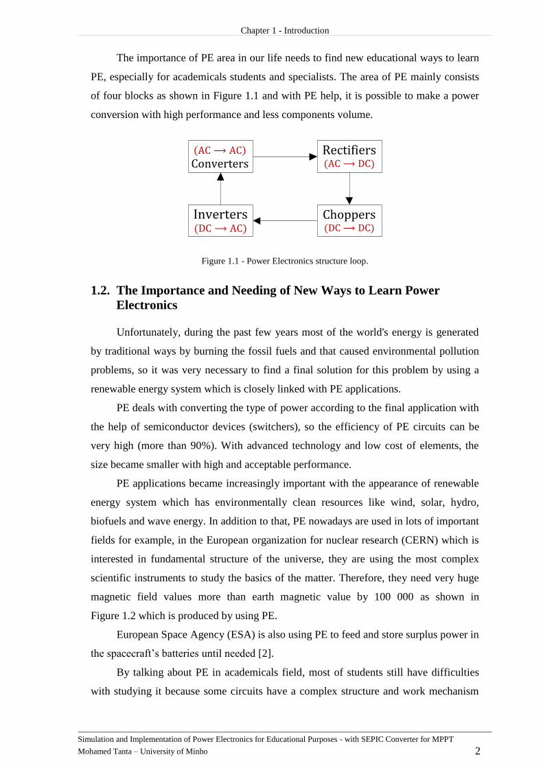
The importance of PE area in our life needs to find new educational ways to learn
PE, especially for academicals students and specialists. The area of PE mainly consists
of four blocks as shown in Figure 1.1 and with PE help, it is possible to make a power
conversion with high performance and less components volume.
Figure 1.1 - Power Electronics structure loop.
The Importance and Needing of New Ways to Learn Power 1.2.
Electronics
Unfortunately, during the past few years most of the world's energy is generated
by traditional ways by burning the fossil fuels and that caused environmental pollution
problems, so it was very necessary to find a final solution for this problem by using a
renewable energy system which is closely linked with PE applications.
PE deals with converting the type of power according to the final application with
the help of semiconductor devices (switchers), so the efficiency of PE circuits can be
very high (more than 90%). With advanced technology and low cost of elements, the
size became smaller with high and acceptable performance.
PE applications became increasingly important with the appearance of renewable
energy system which has environmentally clean resources like wind, solar, hydro,
biofuels and wave energy. In addition to that, PE nowadays are used in lots of important
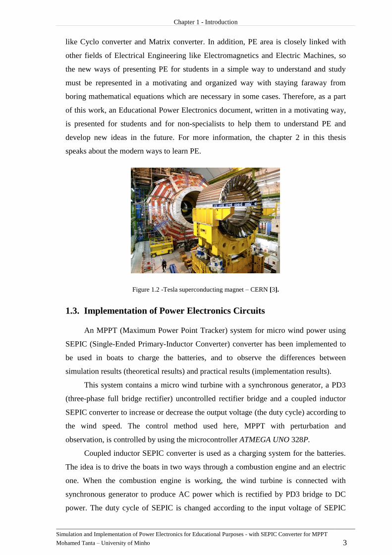
fields for example, in the European organization for nuclear research (CERN) which is
interested in fundamental structure of the universe, they are using the most complex
scientific instruments to study the basics of the matter. Therefore, they need very huge
magnetic field values more than earth magnetic value by 100 000 as shown in
Figure 1.2 which is produced by using PE.
European Space Agency (ESA) is also using PE to feed and store surplus power in
the spacecraft’s batteries until needed [2].
By talking about PE in academicals field, most of students still have difficulties
with studying it because some circuits have a complex structure and work mechanism
Chapter 1 - Introduction
Simulation and Implementation of Power Electronics for Educational Purposes - with SEPIC Converter for MPPT
Mohamed Tanta – University of Minho 3
like Cyclo converter and Matrix converter. In addition, PE area is closely linked with
other fields of Electrical Engineering like Electromagnetics and Electric Machines, so
the new ways of presenting PE for students in a simple way to understand and study
must be represented in a motivating and organized way with staying faraway from
boring mathematical equations which are necessary in some cases. Therefore, as a part
of this work, an Educational Power Electronics document, written in a motivating way,
is presented for students and for non-specialists to help them to understand PE and
develop new ideas in the future. For more information, the chapter 2 in this thesis
speaks about the modern ways to learn PE.
Figure 1.2 -Tesla superconducting magnet – CERN [3].
Implementation of Power Electronics Circuits 1.3.
An MPPT (Maximum Power Point Tracker) system for micro wind power using
SEPIC (Single-Ended Primary-Inductor Converter) converter has been implemented to
be used in boats to charge the batteries, and to observe the differences between
simulation results (theoretical results) and practical results (implementation results).
This system contains a micro wind turbine with a synchronous generator, a PD3
(three-phase full bridge rectifier) uncontrolled rectifier bridge and a coupled inductor
SEPIC converter to increase or decrease the output voltage (the duty cycle) according to
the wind speed. The control method used here, MPPT with perturbation and
observation, is controlled by using the microcontroller ATMEGA UNO 328P.
Coupled inductor SEPIC converter is used as a charging system for the batteries.
The idea is to drive the boats in two ways through a combustion engine and an electric
one. When the combustion engine is working, the wind turbine is connected with
synchronous generator to produce AC power which is rectified by PD3 bridge to DC
power. The duty cycle of SEPIC is changed according to the input voltage of SEPIC

Chapter 1 - Introduction
Simulation and Implementation of Power Electronics for Educational Purposes - with SEPIC Converter for MPPT
Mohamed Tanta – University of Minho 4
(output voltage of the rectifier) to generate the electricity and charge the batteries, as
shown in the diagram of Figure 1.3. This system uses a 450 W wind turbine
(SilentWind 24 V) with permanent magnet synchronous generator.
Figure 1.3 - Micro wind power application using SEPIC converter.
This study is a direct application about the relation between Power Electronics
converters and what is described in the written Educational Power Electronics
document, because this study uses two types of converters, converter (PD3
rectifier) and SEPIC converter (chopper).
Motivations 1.4.
Learning and presenting Power Electronics for the students in a motivating,
organized and easy way to study, with the possibility of getting knowledge through
simulation results, are the main motivations for this Master thesis work. The
implementation of a batteries charging system using a micro wind turbine, with
permanent magnet synchronous generator, three-phase uncontrolled rectifier, coupled
inductor SEPIC converter, and digital controller, are another important motivation.
Objectives and Contributions 1.5.
The objectives and contributions of this work are the following:
Presenting an Educational Power Electronics document for students with theoretical
explanations and with simulations of all the circuits by using PSIM and MATLAB
programs.
Providing the models of the simulated circuits on a CD, which gives the possibility
to check results and change circuits parameters.
Making a copy of the Educational Power Electronics document in 16:9 dimensions
to be used on multimedia devices.
Chapter 1 - Introduction
Simulation and Implementation of Power Electronics for Educational Purposes - with SEPIC Converter for MPPT
Mohamed Tanta – University of Minho 5
Implementing a batteries charging system with MPPT for micro wind turbine using
a coupled inductor SEPIC converter.
Thesis Organization 1.6.
Chapter 1 is an introduction for the main purpose which gives an idea about
needing new motivating ways to learn Power Electronics for the students and the
implemented circuits.
Chapter 2 handles the traditional and modern resources to learn Power Electronics
these days which includes journals, books, video conferencing and Power Electronics
websites.
Chapter 3 handles with Educational Power Electronics document and gives an
idea about its content, presentation and multipurpose Power Electronics circuits.
Chapter 4 talking about simulation of Power Electronics circuits, the ways of
simulation, MATLAB and PSIM programs.
Chapter 5 describes the theoretical information about micro wind power turbine
using SEPIC converter charging batteries system which includes MPPT control,
calculation design for SEPIC converter, driving circuit of MOSFET and ATMEGA 328p
microcontroller.
Chapter 6 contains the experimental results for the system and also makes a
comparison between the theoretical and experimental results for the system.
Chapter 7 contains the conclusion, the problems that should be solved and the
suggestions for the future.


Simulation and Implementation of Power Electronics for Educational Purposes - with SEPIC Converter for MPPT
Mohamed Tanta – University of Minho 7
CHAPTER 2
WhatExistsforLearningPowerElectronics
Introduction 2.1.
Power Electronics (PE) is in constant innovation and renewal, so the researchers
and people who are interested in this field should know always more and more about the
fundamentals of electronics and electrical power areas.
As a result of the importance of PE at the present time, there are many educational
sources for the people who are interested to learn PE and expand their horizons of
knowledge in this field, and because of we are in the age of scientific and technological
evolution, both of computer and the internet grid are appeared to use as a trendy
methods to get as much information as possible about any subject. In addition to that,
the electronics copies of educational books to learn PE which prepared with animated
figures are very suitable for students to analyze and recognize very well the work
mechanism for any complex circuit, also one of the sources to learn PE is the scientific
journals which publish the newest applications of science and the most important
scientific achievements. Also we do not have to ignore the role of traditional PE books
which are also the primary source to learn PE.
As a result, the available options to study PE can be classified as:
1- Electronic Learning Sources, which are Divided into:
1- PE websites and interactive forums.
2- Video conferencing and educational videos.
3- Electronic books which provided with animated figures.
4- Specific educational books written by the manufacturer.
5- Social network websites which include a content of interactive groups.
2- Traditional Learning Sources, which Divided into:
1- Scientific journals.
2- Traditional books.
3- Modeling and Simulation Programs

Chapter 2 – What Exists for Learning Power Electronics
Simulation and Implementation of Power Electronics for Educational Purposes with SEPIC Converter for MPPT
Mohamed Tanta – University of Minho 8
Electronic Learning Sources 2.2.
Electronic learning nowadays using all of multimedia devices which include lots
of available information on the internet grid in different fields to facilitate students
realizing for scientific subjects according to their abilities at any time.
The education in age of communication and information technology is a worthy
commodity, so it is important these days to realize that we have to deal with education
process in a different way from the past, so that is possible today to exchange the
information, develop the communication between people, gathering and analysis
information to find good solutions for many problems.
Some benefits for electronic educational sources [4]:
1- The big effectiveness for electronic educational sources that increase the ability
of learning and recall the information.
2- Less costs and saving more time because of the student does not have to go
every day to a university or any educational institute.
3- More flexibility than traditional learning sources which means that the student
can access to his educational program at any time.
4- The possibility to choose the level of education, whether for beginner students,
professional students or for craftsmen.
Power Electronics Websites and Interactive Forums 2.2.1.
These websites are designed to help people, especially students, job seekers and
working engineers who need information about PE completely from the basics to
advanced levels. In addition, these websites have forums for discussion about any
scientific idea with specialists and experts opinions that will confirm and make the
educational process more interesting.
Also one of the features for these websites is they are always constantly in
innovation and evolution for the information which fitting with the development of
technology. These websites are often associated with researching centers or the
universities and they are among the easiest and cheapest ways to study PE.
Some examples for tutorial PE websites, which are completely free, are shown in
Figure 2.1.
“www.completepowerelectronics.com” and “www.powerelectronics.com”.

Chapter 2 – What Exists for Learning Power Electronics
Simulation and Implementation of Power Electronics for Educational Purposes with SEPIC Converter for MPPT
Mohamed Tanta – University of Minho 9
Figure 2.1- Some examples of tutorial power electronics websites.
Video Conferencing and Educational Videos 2.2.2.
The video conference is a broadcasting live lectures from a site to several sites
which separated by distances. The process of sending and receiving information will be
as an interactive and direct process between members by using the internet grid,
cameras and monitors.
This way gives the best opportunity to learn PE for as many people as possible,
also one of the most modern applications for video conference which is related to with
engineering science is a telemedicine system which allows for doctors to confer or
doing some surgical operations through video and robot system [5].
The differences between learning PE through video conference system and
normal educational videos is that video conference system is a real time system or
synchronous information delivery system as shown in Figure 2.2, while normal
educational videos is an asynchronous information delivery system (later time).
Both ways are very preferable to learn PE and any other fields because this way is
very interesting and motivating for students, also it helping for reminding the new
concepts for a long time more than other ways, in addition of increasing the ability to
understand new difficult ideas.
Figure 2.2 - Video conference system [6].

Chapter 2 – What Exists for Learning Power Electronics
Simulation and Implementation of Power Electronics for Educational Purposes with SEPIC Converter for MPPT
Mohamed Tanta – University of Minho 10
Electronic Books which are Provided with Animated Figures 2.2.3.
Animated figures are defined as a group of drawings which are displayed behind
each other in sequential mode and regular presentation speed to give at the end a sense
of motion on screen, making the learning process interesting and motivating for students
to increase the ability of realizing new concepts.
It is possible to give the movement for the most of photos and graphics to clarify
most of unclear points or to explain some difficult ideas, so the movement of drawings
here gives the motivation for student to learn more and leads to increasing the physical
sense for learners, also it can provide this motion accompanied with sounds and
clarification texts and in this case will be similar to videos. In PE field, there are lots of
circuits with complex work mechanism (for example: cycloconverter and multi-level
inverter) that present their work mechanisms in this way leads to simplify the learning
process and make easier cognition for students whatever the circuit was complex.
This learning method is still a modern method and has a limited spread comparing
with other methods, also most of electronics books which provided with animated
figures are not free and expensive but it is possible to find some websites on the internet
which provide the explanation for some simple electronic circuits and it is completely
free.
Special Educational Books Written by the Manufacturer 2.2.4.
These books are normally written by the company that manufactured the device
and the main purpose of these books is to describe and explain about the products, how
to use it, and product advantages, so these books are not for a category of beginner
students who want to learn the basics in PE. It is more for a category of engineers and
specialist people because these books are talking about a specific application and the
achievements of company in this field to facilitate product marketing process.
The main features of these books are:
1- Usually these books are accompanied with real clarification figures of products.
2- They includes the designing values of product (datasheet).
3- Explanations about work mechanism and the product installation.
4- Keep up with the last version of product.
5- Most of these books are completely free (download from the company website).
For example: a book about HVDC (High Voltage Direct Current) for beginners
and beyond is written by ALSTOM company (ALSTOM is a French multinational

Chapter 2 – What Exists for Learning Power Electronics
Simulation and Implementation of Power Electronics for Educational Purposes with SEPIC Converter for MPPT
Mohamed Tanta – University of Minho 11
company which holds interests in the electricity generation and rail transport markets),
so this book is an educational book about specific application (HVDC) and in the same
time it aims to marketing the product [7].
Another book from ABB company (ABB is a multinational corporation
headquartered in Zurich, Switzerland, operating mainly in robotics and the power and
automation technology areas) talking about the solutions for photovoltaic protections as
shown in Figure 2.3 [8].
Figure 2.3 – HVDC book written by ALTSOM and Photovoltaic book written by ABB [7] [8].
Social Network Websites which Include a Content of Interactive Groups 2.2.5.
Social websites started recently to spread very rapidly between people and they
are known as “the new social media”, which are always in development and in
continuous widespread.
These websites are the newest communication technology products and the most
popular websites on the internet. Although these websites were established for social
communication between people, nowadays they are also being used for scientific
activities.
Some of the most famous social websites are Facebook and Twitter, and the first
social website in the world is a Facebook with more than 700 million members. It
normally consists of some social groups and pages which have specific targets and some
of them are specialized about PE with different levels for students.
In this case, the student’s responsibility is only to join for one of these educational
groups which talking about PE before being able to discuss in any topic.

Chapter 2 – What Exists for Learning Power Electronics
Simulation and Implementation of Power Electronics for Educational Purposes with SEPIC Converter for MPPT
Mohamed Tanta – University of Minho 12
The features of these websites are:
1- Full possibility to ask any question for members.
2- Speed responding, especially if the group has lots of members.
3- The possibility of discussion about any topic with members.
4- Most of these groups have permanent updating for the information.
The disadvantages of this way to learn PE is a lack of information reliability, by
another meaning, the student must be careful to choose the true information when a
scientific discussion happens between members because most of those members are not
specialized people.
Traditional Learning Sources 2.3.
Every work in this life has positive and negative sides, and that also applying for
electronic learning way which depends on computer and internet grid.
The internet grid is an open information system where any user can have his own
website which includes lots of inaccurate information and that leads to damage and
harm the academic integrity. Therefore, the importance of traditional learning sources
which usually are not free and not available for all categories like books and scientific
journals that these sources characterized by a full accurate information and still
preferable for some people in spite of a widespread of electronic learning sources and
that for sure applying for any field of study, including PE. We will talk later in some
details about the traditional sources to learn PE.
Power Electronics Journals 2.3.1.
PE journals have two kinds, one of them called educational journals which
interested in publishing the recent news and applications of PE area in a simple way for
normal people and non-specialists and the second one called academic journals which
published for researchers and academic people (specialist people).
Normally, these journals have two published ways, virtual journal contains a
collection of previously published paper in a scientific style, and hard copy journal to
facilitate its spread between people as much as possible. The headline and the main
topics for every copy of this journal are determined by an editorial team according to
their relevance. Therefore, it is not necessary that the journal be always restricted to
specific topics.
Chapter 2 – What Exists for Learning Power Electronics
Simulation and Implementation of Power Electronics for Educational Purposes with SEPIC Converter for MPPT
Mohamed Tanta – University of Minho 13
Usually most of these journals are not free because it contains lots of innovation
and updated information in PE field and some of these academic journals are related to
research bodies and the universities around the world, so these journals are not a good
choice for people who want to learn the basics in PE but on the opposite, it is a good
reference for specialists and researchers.
The advantages of these virtual journals are [9]:
1- Quick access to the previously published papers in a scientific style.
2- Valuable commentary that provided by researchers and academic team.
3- Provide the links for full-text articles and the reference journal.
4- Comfortable browse and links to previous issues.
Some examples of PE academic journal is an International Journal of
Advancements in Power Electronics & Digital Devices which includes original research
and innovation ideas, applications from all over the world.
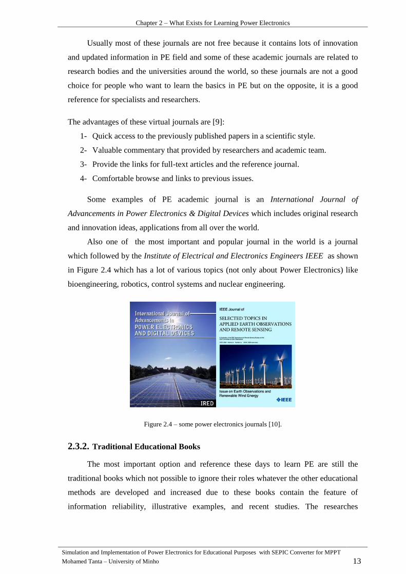
Also one of the most important and popular journal in the world is a journal
which followed by the Institute of Electrical and Electronics Engineers IEEE as shown
in Figure 2.4 which has a lot of various topics (not only about Power Electronics) like
bioengineering, robotics, control systems and nuclear engineering.
Figure 2.4 – some power electronics journals [10].
Traditional Educational Books 2.3.2.
The most important option and reference these days to learn PE are still the
traditional books which not possible to ignore their roles whatever the other educational
methods are developed and increased due to these books contain the feature of
information reliability, illustrative examples, and recent studies. The researches

Chapter 2 – What Exists for Learning Power Electronics
Simulation and Implementation of Power Electronics for Educational Purposes with SEPIC Converter for MPPT
Mohamed Tanta – University of Minho 14
nowadays indicated that reading electronics books is harder than reading traditional
ones.
Sometimes, the traditional books are more preferable to read for students and
researchers, but that does not mean ignoring the electronic learning sources. Despite of
the fact that electronic books have recently spread very quickly, but they still need lots
of time to eliminate the effect of traditional books which are indispensable for anyone
because they supposed as a permanent reference and can be stored for a long time on the
opposite of electronic storage tools which can be damaged at any time.
Both traditional and electronic books have their own features. For example, the
electronic books can contain animation figures which increase the ability of realizing
the new ideas, while the traditional books are more organized, have a logical sequence
of ideas, and suitable for all student levels. Also it is important to know that these books
are always updated to new editions to avoid old mistakes and keep up with the latest
developments in PE, so it can be found the same book of the same author with different
editions.
Modeling and Simulation Programs 2.4.
According to these programs, a student can simulate any circuit and detect both of
transient and stable results. Usually these programs consist of a dialogic interface with
student which allows for student to make a simulation and observe the results before
they are applied on reality.
Circuits simulation is a one of the newest way of self-learning PE because it helps
the student to predict and conclude the results, on the other hand, usually the simulation
is accompanied with the other previous learning ways, for example student can study
any circuit and see its work mechanism results before doing the simulation which must
to confirm the same results.
Nowadays, lots of simulation programs are available to do the simulation for
electrical circuits and the most popular program for simulation and modeling is a
MATLAB which consists of lots of libraries and every library is responsible for a
specific purpose. Simulink and Simpowersystem libraries are using to simulate Power
Electronics circuits and every model could be accompanied with editor file as a
definition file to define the variables which including inside the model file.
Also one of the most popular simulation programs is PSIM, and the main feature
of this program that it accepts the simulation with C+ language, in order to simulate a

Chapter 2 – What Exists for Learning Power Electronics
Simulation and Implementation of Power Electronics for Educational Purposes with SEPIC Converter for MPPT
Mohamed Tanta – University of Minho 15
microcontroller program. MULTISIM program, from National Instruments company, is
also a popular program to make simulations of PE circuits.
Conclusion 2.5.
After making a review about PE learning sources, traditional and modern ones, it
is very clear that every option has its own advantages and disadvantages, and that there
is no perfect option to learn PE.
The most important point which the student must know is that any information
source must be accurate, recommended and reliable, in order to learn PE. Although
traditional PE sources are more reliable and trusty, at the same time they can be boring
for students, because they usually contain lots of theoretical information and
mathematical equations (which in some cases are unnecessary).
In the end, the learner must choose the best option to learn PE according to many
points, like his skills and the level of his previous knowledge. Although the traditional
ways are typically the slowest ways to understand and remember new ideas, it is not
possible to ignore them, because they are references for teaching and learning processes.


Simulation and Implementation of Power Electronics for Educational Purposes - with SEPIC Converter for MPPT
Mohamed Tanta – University of Minho 17
CHAPTER 3
TheoryofPowerElectronicsCircuits
Introduction 3.1.
This chapter presents the Educational Power Electronics document, which was
prepared in the scope of this Master thesis for students and people who are not
specialists in Power Electronics, to make this area of Electrical Engineering as much
available as possible. Also, this chapter presents theory of PE circuits, as well as multi-
purpose PE circuits that can work in many possibilities, according to the driving way of
semiconductor elements.
Multi-Purpose Power Electronics Circuit 3.2.
This chapter gives an idea about the simulation of PE circuits and multi-purposes
circuits which described in PE document:
1- converters (Rectifiers) P-PD-S groups.
2- Rectifier groups (ways of linking) Dual converter, 12,18,24 pulse converter.
3- converters (Choppers).
4- converters (Inverters).
5- converters voltage regulators, cycloconverter, and matrix converter.
Inside these five parts there are multi-purpose circuits that can work depending on
driving method of semiconductor elements like Graetz bridge or H bridge can work as
an rectifier, chopper, or full bridge inverter. In addition, dualconverter and
cycloconverter have exactly the same circuit topology but driving method for the
elements is completely different.
Graetz Bridge (H Bridge) 3.3.
This bridge is a symmetrical bridge, and Figure 3.1 shows the feeding points for
this bridge (A,B for AC side and D,C for DC side) so it can work on three groups of
converters:
1- converters (Rectifiers).

Chapter 3 – Theory of Power Electronics Circuits
Simulation and Implementation of Power Electronics for Educational Purposes with SEPIC Converter for MPPT
Mohamed Tanta – University of Minho 18
a- Full controlled bridge.
b- Symmetrical half controlled bridge
c- Asymmetrical half controlled bridge.
2- converters (Choppers) full bridge chopper.
3- converters (Inverters) full bridge inverter.
Figure 3.1 - Graetz bridge feeding points.
Graetz Bridge Rectifier 3.3.1.
Graetz bridge rectifier could be full controlled (4 SCR – Silicon Controlled
Rectifier), half controlled (2 SCR, 2 Diodes) or uncontrolled (4 diodes) depending on
the type of semiconductor elements and it is also called full-wave rectifier which
convert the whole of the input voltage to DC voltage with the same polarity, to achieve
that, we need four semiconductor elements, each two of them work in a half of the cycle
(positive and negative one).
3.3.1.1.Full controlled Greaetz Bridge Rectifier
It is possible to change the value of firing angle by using SCRs instead of diodes
but to achieve single phase bridge rectifier, it should to create two AC signals with shift
angle between them equals to , so using center tapped transformer leads to get
double output voltage. Figure 3.2 shows center tapped transformer with PD2 (single-
phase rectifier) bridge and Figure 3.3 shows the results at resistive load and firing angle
.
Work mechanism for this bridge is completely depending on naturally
commutated process between the elements.
The average output voltage is given by the equation:
Chapter 3 – Theory of Power Electronics Circuits
Simulation and Implementation of Power Electronics for Educational Purposes with SEPIC Converter for MPPT
Mohamed Tanta – University of Minho 19
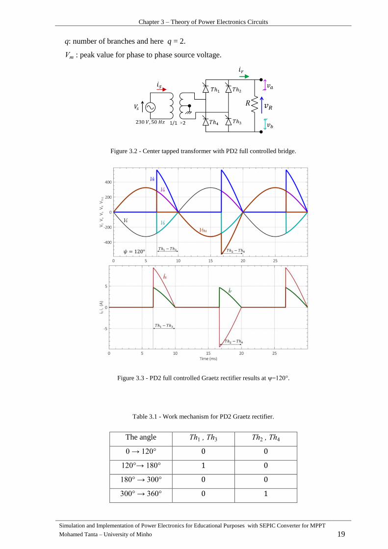
q: number of branches and here q = 2.
: peak value for phase to phase source voltage.
Figure 3.2 - Center tapped transformer with PD2 full controlled bridge.
Figure 3.3 - PD2 full controlled Graetz rectifier results at .
Table 3.1 - Work mechanism for PD2 Graetz rectifier.
The angle

Chapter 3 – Theory of Power Electronics Circuits
Simulation and Implementation of Power Electronics for Educational Purposes with SEPIC Converter for MPPT
Mohamed Tanta – University of Minho 20
3.3.1.2.Half Controlled Symmetrical Graetz Bridge Rectifier
Symmetrical PD2 bridge means that one of load voltage points is always
connected to the common cathodes point, which is related to the same type of
semiconductor elements and the other load voltage point is always connected to the
common anodes point which is also related to the same type of semiconductor elements
as shown in Figure 3.4. Therefore, this bridge means that, there are always common
anodes or cathodes point which is related to the same type of semiconductor elements.
Work mechanism for this bridge during a half cycle of the positive wave must
be in forward bias when also applying trigger pulses or a firing angle on its gate, also
diode is still connected during the period . This leads to make a short line
between and points especially in the inductive load case as shown in Figure 3.5 [11].
Figure 3.4 - PD2 Symmetrical Half-Controlled Bridge.
Figure 3.5 - Symmetrical Half bridge Results (Inductive load).

Chapter 3 – Theory of Power Electronics Circuits
Simulation and Implementation of Power Electronics for Educational Purposes with SEPIC Converter for MPPT
Mohamed Tanta – University of Minho 21
Consequently, during this period of time and are working together and that leads
to make the output voltage value equals to zero. The same process is also repeated
between and , so in each cycle there are two short circuit durations. The
average value of the output voltage is:
∫
The peak value of output voltage happens when the firing angle , and in this
case:
m
Table 3.2 - Work mechanism for symmetrical PD2 Graetz rectifier.
The angle
3.3.1.3.Half Controlled Asymmetrical Graetz Bridge Rectifier
Asymmetrical PD2 bridge means that one of the load voltage points (for example
point ) is always connected to the common cathodes point that related to different type
of semiconductor elements and the other load voltage point (point ) is always
connected to the common anodes point which is also related with a different type of
semiconductor elements, so this asymmetrical bridge means that there are always a
common anodes or cathodes points which are related with different types of
semiconductor elements as shown in Figure 3.6.
Work mechanism for this bridge during the positive half cycle of the wave
must be in a forward bias when applying trigger pulses or a firing angle on its gate,
and also the diode starts to connect at . That leads to force to stop
working, so works just during period . That leads to make a short line
between point and during - . Consequently, during this period of
time and are working together and that leads to make the output voltage value
equals to zero as shown in Figure 3.7. The same process is still repeated, so in each
cycle there are two short circuit durations.

Chapter 3 – Theory of Power Electronics Circuits
Simulation and Implementation of Power Electronics for Educational Purposes with SEPIC Converter for MPPT
Mohamed Tanta – University of Minho 22
Figure 3.6 - PD3 Asymmetrical Half-Controlled Bridge.
The Average value of output voltage is:
∫ m
m
The max value of output voltage happens when the firing angle , and in this
case:
c
m
c
Figure 3.7 - PD2 Asymmetrical Half-Controlled Bridge Results.

Chapter 3 – Theory of Power Electronics Circuits
Simulation and Implementation of Power Electronics for Educational Purposes with SEPIC Converter for MPPT
Mohamed Tanta – University of Minho 23
Table 3.3 - Work mechanism for asymmetrical PD2 Graetz rectifier.
The angle
Graetz Bridge (H Bridge) Chopper 3.3.2.
In this case, the source is connected at DC points (D,C points) as shown
in Figure 3.8, also the work mechanism has both natural and forced commutation cases.
To drive DC machine in four quadrants (both of output voltage and current could
be positive or negative), it should to use full bridge chopper or H bridge to run this
machine as a motor or a generator (braking) as shown in Figure 3.8, also the main
feature of this converter that the output voltage could be totally controlled by the
magnitude and the polarity.
Figure 3.8 - Full bridge chopper circuit.
In case of firing the elements during the period , the machine will work
as a motor and starts to rotate in clockwise direction (First quadrant) and the bridge
works as a buck converter (Step-down chopper) also the elements still in reverse
bias state. When switch is disconnected and still works, the current of machine
still flows through and the load voltage equals to zero, next if switch is
disconnected, the current still flows through and the chopper works in the fourth
quadrant (Boost converter).
In case of firing the elements during the period , the machine will work
as a motor and starts to rotate in opposite clockwise direction (Third quadrant) and the

Chapter 3 – Theory of Power Electronics Circuits
Simulation and Implementation of Power Electronics for Educational Purposes with SEPIC Converter for MPPT
Mohamed Tanta – University of Minho 24
bridge works as a buck converter (Step-down chopper) also the elements still in
reverse bias state. When switch is disconnected and still works, the current of
machine still flows through and voltage load equals to zero, next if switch is
disconnected the current still flows through and the chopper works in the
second quadrant (Boost converter) as shown in Figure 3.9. The average output voltage
can be changed by the controlling in duty cycle for each converter but driving
process for this full bridge must be integrated process, so .
∫ t
∫ t
∫
∫
E
- When -
- When
- When and the current has a positive
value (motor rotates in clockwise direction)or negative value
(braking status) as shown in Figure 3.9.
- When
and the current has a positive
value (braking status) or negative value (motor rotates in
opposite clockwise direction).
Chapter 3 – Theory of Power Electronics Circuits
Simulation and Implementation of Power Electronics for Educational Purposes with SEPIC Converter for MPPT
Mohamed Tanta – University of Minho 25
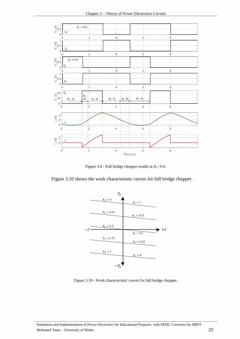
Figure 3.9 - Full bridge chopper results at .
Figure 3.10 shows the work characteristic curves for full bridge chopper.
Figure 3.10 - Work characteristic curves for full bridge chopper.
Chapter 3 – Theory of Power Electronics Circuits
Simulation and Implementation of Power Electronics for Educational Purposes with SEPIC Converter for MPPT
Mohamed Tanta – University of Minho 26
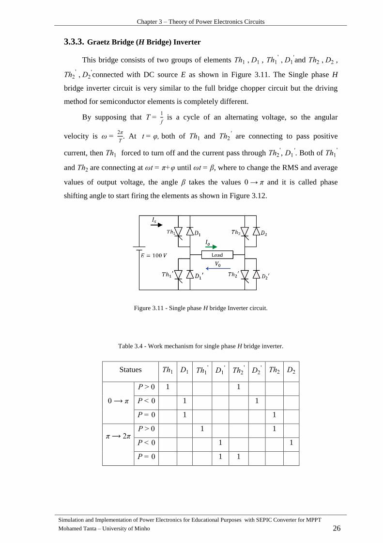
Graetz Bridge (H Bridge) Inverter 3.3.3.
This bridge consists of two groups of elements ,
and ,
connected with DC source E as shown in Figure 3.11. The Single phase H
bridge inverter circuit is very similar to the full bridge chopper circuit but the driving
method for semiconductor elements is completely different.
By supposing that
is a cycle of an alternating voltage, so the angular
velocity is
. At both of and
are connecting to pass positive
current, then forced to turn off and the current pass through ,
. Both of
and are connecting at until , where to change the RMS and average
values of output voltage, the angle takes the values and it is called phase
shifting angle to start firing the elements as shown in Figure 3.12.
Figure 3.11 - Single phase H bridge Inverter circuit.
Table 3.4 - Work mechanism for single phase H bridge inverter.
Statues
1 1
1 1
1 1
1 1
1 1
1 1

Chapter 3 – Theory of Power Electronics Circuits
Simulation and Implementation of Power Electronics for Educational Purposes with SEPIC Converter for MPPT
Mohamed Tanta – University of Minho 27
Figure 3.12 - Single phase H bridge Inverter results.
Load current must stay continuous and it has three work cases. Therefore, the first
case happens when the current passes through a closed loop like
( equals to
zero). The second case happens when the current passes from the source load ( is
positive). The third case happens when the current passes from the load source ( is
negative).
Three Phase PD3 Dualconverter 3.4.
Full controlled converter can work as a rectifier ( or as an inverter
( , but in both cases the power is transferring from AC DC and the
direction of power could be changed because the full controlled converter can
produce a reversible direct output voltage (with two direction of voltage) but still
produces one direction output current, so this dualconverter can work in four quadrants
as shown in Figure 3.14 instead of use one bridge with an inverse breaker and it can be
used to drive DC machines to work as a motor or a generator.
If two bridges are connected to each other and working together to feed the load
with two power directions as shown in Figure 3.13, in this case, it is possible to make a
controlling in power flow with two directions depending on which bridge works as a
rectifier and the other bridge certainly works as an inverter or in stopping mode.
Therefore, There are two types of work mechanism for this dualconverter:
1- Working without circulation current between bridges:
Always one bridge works and the other one stopping (floating mode).
Circulation current: the current passes through two bridges and it is not related
to the load current. This current has a big value in normal cases.
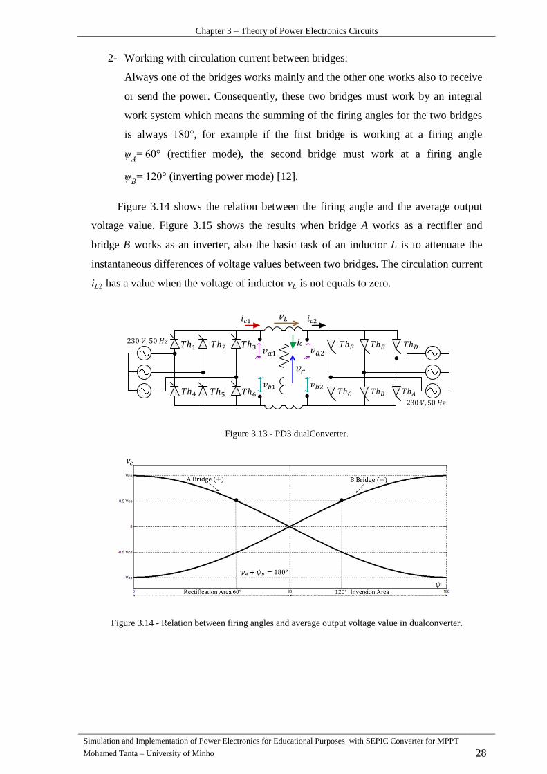
Chapter 3 – Theory of Power Electronics Circuits
Simulation and Implementation of Power Electronics for Educational Purposes with SEPIC Converter for MPPT
Mohamed Tanta – University of Minho 28
2- Working with circulation current between bridges:
Always one of the bridges works mainly and the other one works also to receive
or send the power. Consequently, these two bridges must work by an integral
work system which means the summing of the firing angles for the two bridges
is always , for example if the first bridge is working at a firing angle
(rectifier mode), the second bridge must work at a firing angle
(inverting power mode) [12].
Figure 3.14 shows the relation between the firing angle and the average output
voltage value. Figure 3.15 shows the results when bridge A works as a rectifier and
bridge B works as an inverter, also the basic task of an inductor is to attenuate the
instantaneous differences of voltage values between two bridges. The circulation current
has a value when the voltage of inductor is not equals to zero.
Figure 3.13 - PD3 dualConverter.
Figure 3.14 - Relation between firing angles and average output voltage value in dualconverter.
ic
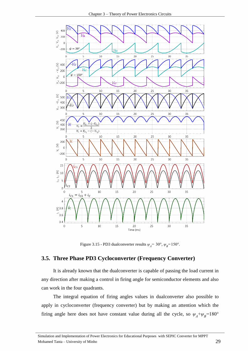
Chapter 3 – Theory of Power Electronics Circuits
Simulation and Implementation of Power Electronics for Educational Purposes with SEPIC Converter for MPPT
Mohamed Tanta – University of Minho 29
Figure 3.15 - PD3 dualconverter results ,
.
Three Phase PD3 Cycloconverter (Frequency Converter) 3.5.
It is already known that the dualconverter is capable of passing the load current in
any direction after making a control in firing angle for semiconductor elements and also
can work in the four quadrants.
The integral equation of firing angles values in dualconverter also possible to
apply in cycloconverter (frequency converter) but by making an attention which the
firing angle here does not have constant value during all the cycle, so
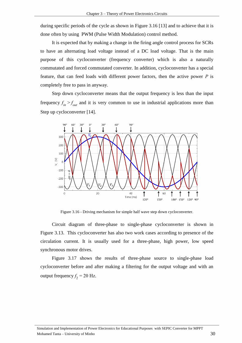
Chapter 3 – Theory of Power Electronics Circuits
Simulation and Implementation of Power Electronics for Educational Purposes with SEPIC Converter for MPPT
Mohamed Tanta – University of Minho 30
during specific periods of the cycle as shown in Figure 3.16 [13] and to achieve that it is
done often by using PWM (Pulse Width Modulation) control method.
It is expected that by making a change in the firing angle control process for SCRs
to have an alternating load voltage instead of a DC load voltage. That is the main
purpose of this cycloconverter (frequency converter) which is also a naturally
commutated and forced commutated converter. In addition, cycloconverter has a special
feature, that can feed loads with different power factors, then the active power is
completely free to pass in anyway.
Step down cycloconverter means that the output frequency is less than the input
frequency
and it is very common to use in industrial applications more than
Step up cycloconverter [14].
Figure 3.16 - Driving mechanism for simple half wave step down cycloconverter.
Circuit diagram of three-phase to single-phase cycloconverter is shown in
Figure 3.13. This cycloconverter has also two work cases according to presence of the
circulation current. It is usually used for a three-phase, high power, low speed
synchronous motor drives.
Figure 3.17 shows the results of three-phase source to single-phase load
cycloconverter before and after making a filtering for the output voltage and with an
output frequency Hz.
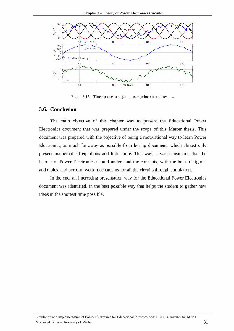
Chapter 3 – Theory of Power Electronics Circuits
Simulation and Implementation of Power Electronics for Educational Purposes with SEPIC Converter for MPPT
Mohamed Tanta – University of Minho 31
Figure 3.17 – Three-phase to single-phase cycloconverter results.
Conclusion 3.6.
The main objective of this chapter was to present the Educational Power
Electronics document that was prepared under the scope of this Master thesis. This
document was prepared with the objective of being a motivational way to learn Power
Electronics, as much far away as possible from boring documents which almost only
present mathematical equations and little more. This way, it was considered that the
learner of Power Electronics should understand the concepts, with the help of figures
and tables, and perform work mechanisms for all the circuits through simulations.
In the end, an interesting presentation way for the Educational Power Electronics
document was identified, in the best possible way that helps the student to gather new
ideas in the shortest time possible.


Simulation and Implementation of Power Electronics for Educational Purposes - with SEPIC Converter for MPPT
Mohamed Tanta – University of Minho 33
CHAPTER 4
SimulationofPowerElectronicCircuits
Introduction 4.1.
The model for any economic problem or administrative, scientific or military is
only a simplified model of this problem, which mostly takes the form of equations and
mathematical functions represent the variables that can be quantified for different
factors, so the model is a simplified representation or description of a real situation or
phenomena. After building the model of any problem, it is possible to simulate the
system, where the simulation is a tool to make the real system equivalent to the virtual
one, which should act in a similar way to the real system, giving the same or
minimizing results in the case of having the same real system inputs [15].
The modeling process for any problem must consider these two points:
1- System conception, which includes full understanding and knowledge of the real
system, taking into consideration system pre-dimension and the feasibility of the
model in case of needing any changes in the future.
2- System optimization, which includes reduction in the system costs (design and
implementation costs) and improvement in the system efficiency by using
intelligent system control [16].
These points must be taken into consideration before simulating any PE system,
which means understand and determine the inputs, outputs, variables values and
constant values of the system, after that the optimization process should start to
decrease unnecessary points.
Modeling and Simulation Type 4.2.
Normally, there are three main types of models which sorted as the following:
1- Mathematical models which can be divided into two types:
a- Analytic model: it has a solution of equations used to describe system changes
that can be expressed as a mathematical analytic function.
For example, the wind turbine output power equation is:
: Air density, : wind speed, : rotor swept area.
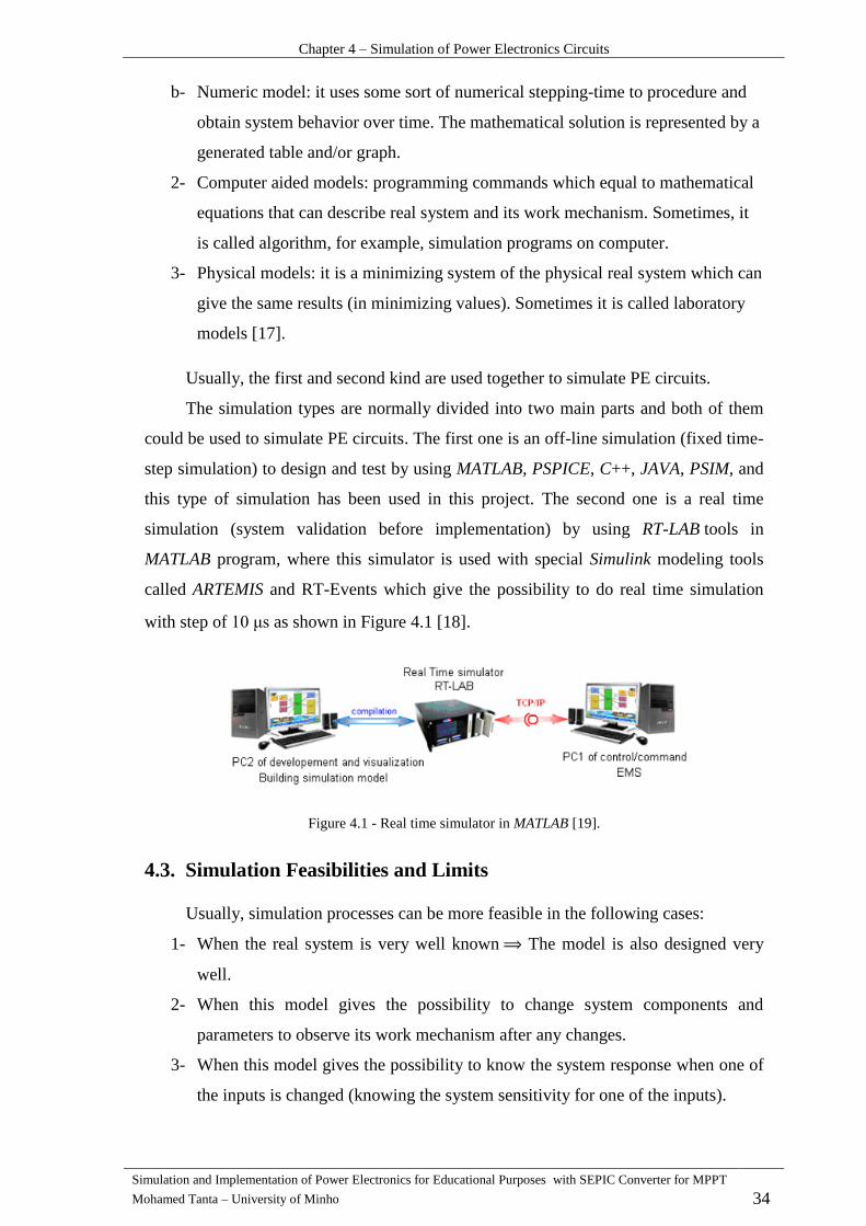
Chapter 4 – Simulation of Power Electronics Circuits
Simulation and Implementation of Power Electronics for Educational Purposes with SEPIC Converter for MPPT
Mohamed Tanta – University of Minho 34
b- Numeric model: it uses some sort of numerical stepping-time to procedure and
obtain system behavior over time. The mathematical solution is represented by a
generated table and/or graph.
2- Computer aided models: programming commands which equal to mathematical
equations that can describe real system and its work mechanism. Sometimes, it
is called algorithm, for example, simulation programs on computer.
3- Physical models: it is a minimizing system of the physical real system which can
give the same results (in minimizing values). Sometimes it is called laboratory
models [17].
Usually, the first and second kind are used together to simulate PE circuits.
The simulation types are normally divided into two main parts and both of them
could be used to simulate PE circuits. The first one is an off-line simulation (fixed time-
step simulation) to design and test by using MATLAB, PSPICE, C++, JAVA, PSIM, and
this type of simulation has been used in this project. The second one is a real time
simulation (system validation before implementation) by using RT-LAB tools in
MATLAB program, where this simulator is used with special Simulink modeling tools
called ARTEMIS and RT-Events which give the possibility to do real time simulation
with step of s as shown in Figure 4.1 [18].
Figure 4.1 - Real time simulator in MATLAB [19].
Simulation Feasibilities and Limits 4.3.
Usually, simulation processes can be more feasible in the following cases:
1- When the real system is very well known The model is also designed very
well.
2- When this model gives the possibility to change system components and
parameters to observe its work mechanism after any changes.
3- When this model gives the possibility to know the system response when one of
the inputs is changed (knowing the system sensitivity for one of the inputs).

Chapter 4 – Simulation of Power Electronics Circuits
Simulation and Implementation of Power Electronics for Educational Purposes with SEPIC Converter for MPPT
Mohamed Tanta – University of Minho 35
4- When this model gives the possibility to do a virtual maintenance for the system
to observing the new results.
5- When it allows to training new users for the real system.
Some reasons which limit using of simulation and modeling:
1- When it is not possible to find an equation or a relation between system inputs
and system outputs, like neural networks.
2- When doing the tests for the implemented system is easier than modeling this
system.
3- When the real system is a very complex system ⇒ needed a powerful simulation
program which cost lots of money and the model takes lots of time to do [20].
Power Electronics Simulation Programs 4.4.
There are lots of PE simulation programs. Some of them are specified for huge
systems simulation, and others are more specific for control systems simulation.
Therefore, in this work, two simulation programs have been used: MATLAB and PSIM.
MATLAB Program 4.4.1.
MATLAB is a one of the simulation programs which gives the ability to work in
high level programming environment. Therefore, many new libraries inside the program
recently have been developed.
MATLAB is an abbreviation of matrix-laboratory which is using for scientific and
engineering calculations. This program is a very huge program comparing to PSIM and
it has many benefits like modeling, simulation and prototyping for lots of engineering
problems.
The program in MATLAB normally consists of one or two files, the first file is an
important one and Irreplaceable which calls the Model file and contains the simulation
and modeling for the problem. The second file is not necessary for simulation process
but it could organize and facilitate the simulation which calls the Editor file and
contains the simulation variables and some of C programming code. The program
mainly has four user interfaces:
1- Command window: it is one of the most important user interfaces, which can
be used for enter data and to display results.
2- Work space: this user interface is necessary to use in huge projects because it
helps to manage the work by allowing the user to see and change the values of contents.

Chapter 4 – Simulation of Power Electronics Circuits
Simulation and Implementation of Power Electronics for Educational Purposes with SEPIC Converter for MPPT
Mohamed Tanta – University of Minho 36
3- Command history: this user interface shows the history and changing levels of
the project.
4- Current directory: it is a user interface to find M file (Model file), so any model
you want to run must be in the current directory interface.
To simulate electrical and PE circuits using MATLAB there are two libraries that
can be used. The first library is a Simulink library, which is the main library in
MATLAB, and it is used to simulate different cases, but the problem of using this library
is that we should know about the mathematical equations of the model, otherwise it is
not possible to simulate by using this library.
The second library is a Simpowersystem library, which is used for simulating PE
circuits, and that is easy to use, because it is not necessary to know any mathematical
equation. In some models it is possible to use both libraries together.
4.4.1.1. Using Simulink Library for Simulation
Creating a model file in MATLAB allows for us to use all MATLAB libraries, so
the first step is to create a Model file. Simulink library is the hugest library in MATLAB
and it contains many of sub-libraries inside the main library like Sources sub- library for
input units, Sinks for output units and Math operation sub-library.
As a simple example for using this library, RLC circuit as shown in Figure 4.2 is
simulated by using both Model and Editor files. In the end, we will notice that it is not
simple to use this library for a complex circuits or systems.
Figure 4.2 - RLC Power Circuit.
In this example, the following elements will be used:
- Integrator element to make an integration process (Continuous sub-library).
- Gain and Sum elements (Math sub-library).
- Mux element to make mixing between many signals (Signal and System sub-library).
- Sine wave source and clock timer elements (Sources sub-library).
- Scope element to monitoring the results and Workspace element to organize the
results in a matrix (sinks sub-library).
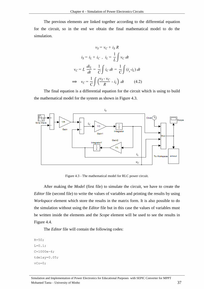
Chapter 4 – Simulation of Power Electronics Circuits
Simulation and Implementation of Power Electronics for Educational Purposes with SEPIC Converter for MPPT
Mohamed Tanta – University of Minho 37
The previous elements are linked together according to the differential equation
for the circuit, so in the end we obtain the final mathematical model to do the
simulation.
∫
∫
∫
∫(
)
The final equation is a differential equation for the circuit which is using to build
the mathematical model for the system as shown in Figure 4.3.
Figure 4.3 - The mathematical model for RLC power circuit.
After making the Model (first file) to simulate the circuit, we have to create the
Editor file (second file) to write the values of variables and printing the results by using
Workspace element which store the results in the matrix form. It is also possible to do
the simulation without using the Editor file but in this case the values of variables must
be written inside the elements and the Scope element will be used to see the results in
Figure 4.4.
The Editor file will contain the following codes:
R=50;
L=0.1;
C=1000e-6;
tdelay=0.05;
vCo=0;
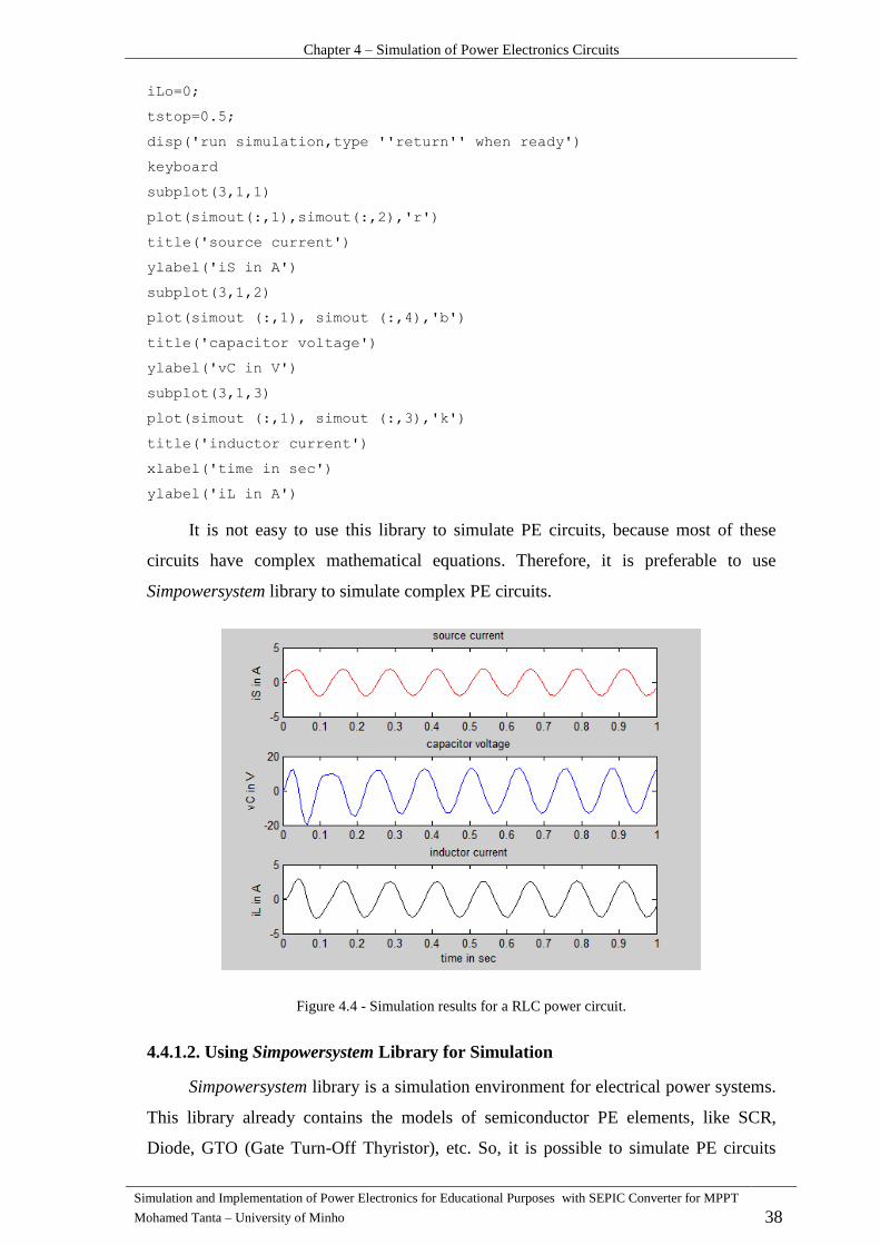
Chapter 4 – Simulation of Power Electronics Circuits
Simulation and Implementation of Power Electronics for Educational Purposes with SEPIC Converter for MPPT
Mohamed Tanta – University of Minho 38
iLo=0;
tstop=0.5;
disp('run simulation,type ''return'' when ready')
keyboard
subplot(3,1,1)
plot(simout(:,1),simout(:,2),'r')
title('source current')
ylabel('iS in A')
subplot(3,1,2)
plot(simout (:,1), simout (:,4),'b')
title('capacitor voltage')
ylabel('vC in V')
subplot(3,1,3)
plot(simout (:,1), simout (:,3),'k')
title('inductor current')
xlabel('time in sec')
ylabel('iL in A')
It is not easy to use this library to simulate PE circuits, because most of these
circuits have complex mathematical equations. Therefore, it is preferable to use
Simpowersystem library to simulate complex PE circuits.
Figure 4.4 - Simulation results for a RLC power circuit.
4.4.1.2. Using Simpowersystem Library for Simulation
Simpowersystem library is a simulation environment for electrical power systems.
This library already contains the models of semiconductor PE elements, like SCR,
Diode, GTO (Gate Turn-Off Thyristor), etc. So, it is possible to simulate PE circuits

Chapter 4 – Simulation of Power Electronics Circuits
Simulation and Implementation of Power Electronics for Educational Purposes with SEPIC Converter for MPPT
Mohamed Tanta – University of Minho 39
without needing to find the mathematical model for the circuits. The library has already
many sub-libraries like power electrical sources, electrical elements, control blocks,
measurements, three-phase machines, power electronics and renewable energy system.
To show how we can use this library in MATLAB, a three-phase controlled
rectifier bridge, as a simple example, with delay angle, is simulated by using
Simpowersystem library as shown in Figure 4.7, that presents the results in Figure 4.6.
After that, the same circuit, with the same variables values, was simulated by PSIM
program, in order to compare the results of both programs. The three-phase rectifier
bridge is shown in Figure 4.5 with the values:
V Hz
Figure 4.5 – Three-phase rectifier bridge.
Figure 4.6 – Three-phase rectifier bridge results by using Simpowersystem library.

Chapter 4 – Simulation of Power Electronics Circuits
Simulation and Implementation of Power Electronics for Educational Purposes with SEPIC Converter for MPPT
Mohamed Tanta – University of Minho 40
Figure 4.7 – Three-phase controlled rectifier bridge model using Simpowersystem library.
Powersim Program (PSIM) 4.4.2.
PSIM is a simulation program which is designed for PE circuits and dynamic
system simulation. This program is using a compact and strong algorithm about

Chapter 4 – Simulation of Power Electronics Circuits
Simulation and Implementation of Power Electronics for Educational Purposes with SEPIC Converter for MPPT
Mohamed Tanta – University of Minho 41
electrical circuits, so the simulation period is very short and the results have very
acceptable accuracy.
PSIM has a comfortable user interface and quick simulation process. Therefore,
PSIM provides powerful results. Any circuit can be created and changed in a very easy
way, also every circuit has a help available for each component.
To handle with a huge electrical system, PSIM provides the sub-circuit function to
be parts of the whole system.
The features of using PSIM for simulation are [21]:
1- PSIM user interface is a powerful, easy to use and that leads to work in more
productivity way.
2- PSIM has a running on virtual test which allows to you change the values of
components during simulation.
3- PSIM is capable to simulate complex and large power systems in very short
period, so it is one of the fastest simulator program for PE circuits.
4- The most important advantage in PSIM that this program has a C+ compiler
which allows to compiling any C+ code directly without using any other
programs. That makes the program very easy to use to implement your control
method.
5- PSIM has a large number of examples which have already done like DC power
supplies, PWM, active filter control loops.
6- PSIM has the ability to move from the design stage to simulation and
implementation stage in the shortest time possible as shown in Figure 4.8.
Figure 4.8 - PSIM environment [22].
As a part of PE simulation, the most important section is to know about how to
simulate the driving for PE switchers, and to do that, PSIM provides four methods as
shown in Figure 4.9 by using:

Chapter 4 – Simulation of Power Electronics Circuits
Simulation and Implementation of Power Electronics for Educational Purposes with SEPIC Converter for MPPT
Mohamed Tanta – University of Minho 42
1- Switch gating block: determines the pulse frequency and the duty cycle for
pulses. It contains number of interruption points during one cycle which at least
must to be 2 points, also it has a number of switching points which must to be
equal to the number of interruption points. Switching points normally take a
values between . This controller is available to control in SCR,
MOSFET, GTO, etc.
2- Alpha controller: it is used for delay angle control to drive SCR or TRIAC
(forced-commutated switches in the switch mode). It has three inputs, enable
input which turn on or turn off the controller, alpha angle input which gives the
delay angle value in degree and sync input which normally make a
synchronization with voltage signal by using voltage sensor and comparator.
The main feature of alpha controller is that the delay angle in degree can be
directly controlled. Normally SCR bridge can be controlled by an alpha
controller. It is also able to dive GTO transistor by using this controller (GTO
transistor is a symmetrical device with both forward-blocking and reverse-
blocking capabilities).
3- On-off controller: the on-off switch controller interfaces between the control
circuit and the power circuit and it is using for self-commutated switches like
MOSFET and BJT (Bipolar Junction Transistor) The MOSFET’s n channel and
npn BJT transistors are turned on when the gate signal is high and the switch is
in positive bias(Collector-Emitter or Drain-Source voltage is positive)
and turned off in case of the gating signal is low. For p channel MOSFET and
pnp BJT transistors are turned on when the gating signal is low and the switch is
in negative bias. The input must to be a logic signal coming from control circuit.
The signal level of 1 is for switch on and 0 for switch off. This controller is a
kind of PWM controller but does not give the value of delay angle directly, so
the user must calculate the value of this angle.
4- PWM controller: the PWM controller has four inputs, enable input which turn
on or turn off the controller, sync input which normally make a synchronization
with voltage signal by using voltage sensor and comparator, delay angle input
which gives the value in degree and M input (modulation index) which selected
the PWM pattern. Normally voltage/current source inverter can be controlled by
a PWM controller [23].

Chapter 4 – Simulation of Power Electronics Circuits
Simulation and Implementation of Power Electronics for Educational Purposes with SEPIC Converter for MPPT
Mohamed Tanta – University of Minho 43
In PSIM program, the BJT transistor is simulated as a voltage signal controlled
transistor instead of current controlled one to facilitate driving process for BJT which
gives the opposite behavior for the BJT in practical life [23].
Figure 4.9 - PSIM controllers for driving power electronics switches.
Simulating a three-phase rectifier bridge circuit with delay angle by using
PSIM must give the same results which have already obtained by using Simpowersystem
library in MATLAB, as shown in Figure 4.11. Since the bridge uses SCR elements, the
controller must be an alpha controller, as shown in Figure 4.10. The black lines refer to
power lines and the red ones refer to control lines.
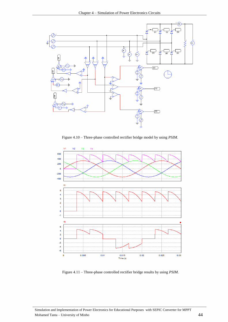
Chapter 4 – Simulation of Power Electronics Circuits
Simulation and Implementation of Power Electronics for Educational Purposes with SEPIC Converter for MPPT
Mohamed Tanta – University of Minho 44
Figure 4.10 – Three-phase controlled rectifier bridge model by using PSIM.
Figure 4.11 – Three-phase controlled rectifier bridge results by using PSIM.

Chapter 4 – Simulation of Power Electronics Circuits
Simulation and Implementation of Power Electronics for Educational Purposes with SEPIC Converter for MPPT
Mohamed Tanta – University of Minho 45
Conclusion 4.5.
Type of Simulation and modeling are presented in this chapter to know the
differences between modeling and simulation. Also, the steps which must to be known
before simulating any problem were presented in order to make an optimum simulation
process (verifying simulation feasibility and limits). The main objective of this chapter
was to present some ideas about PE simulation programs, like PSIM and MATLAB,
which include some sub-libraries. To verify that both PE simulation programs give the
same final result, a three-phase full controlled bridge rectifier was simulated by using
both programs, MATLAB and PSIM. We could conclude that building the model by
using MATLAB is more complex than using PSIM, because of MATLAB has a spacious
simulation environment to simulate all problems but in the same time both of programs
have their strength and weaknesses when they are using for educational or research
purposes like: for educational purposes, PSIM has a simple user interface and has the
simplest model to build circuits and extract the results than Simulink library in
MATLAB. For research purposes, MATLAB has more simulation capability where
Simulink environment gives the possibility to do detailed study on circuit’s behavior
during transient state [24].

Simulation and Implementation of Power Electronics for Educational Purposes - with SEPIC Converter for MPPT
Mohamed Tanta – University of Minho 47
CHAPTER 5
DevelopmentandSimulationResultsoftheMPPT
SystemwithSEPICConverter
Introduction 5.1.
This chapter describes the development and present the simulation results of a
MPPT (Maximum Power Point Tracker) system for a micro wind power turbine, with a
450 W permanent magnet synchronous generator. The MPPT uses a SEPIC converter,
which is applied in charging of batteries.
To simulate the variation of wind speed, it was necessary to use a system with
variable speed drive, where an induction motor controlled by a frequency variator. This
an important device to perform all initial laboratory tests, which allowed a better
generator control as well as to demonstrate the functioning of the system developed.
The generator produces three-phase voltages that need to be rectified, so a three-
phase full wave uncontrolled rectifier PD3 with DC-DC converter (SEPIC converter) is
used here to increase or decrease the value of DC voltage. In addition, the rectifier is
followed by a capacitor filter (condenser) to attenuate the ripples of DC voltage as much
as possible. The control incorporates a MPPT for ideal use of the wind resources and
this control depends on the measured values of input current and voltage to calculate the
instantaneous power value and compare this value with the old value of power to stay
work in the optimal power point as much as possible.
The general diagram for all system was explained in the Figure 1.3.
Wind Power Generator 5.2.
Normally, wind turbine is controlled to work inside limited wind speed domain
which specified between - and - speeds. The turbine must work inside the
domain and beyond of this domain limits, the turbine must stop to prevent it from being
driven by the generator. Figure 5.1 shows the ideal curve of the wind turbine power
which divided to the three sectors according to the wind speed value [25].
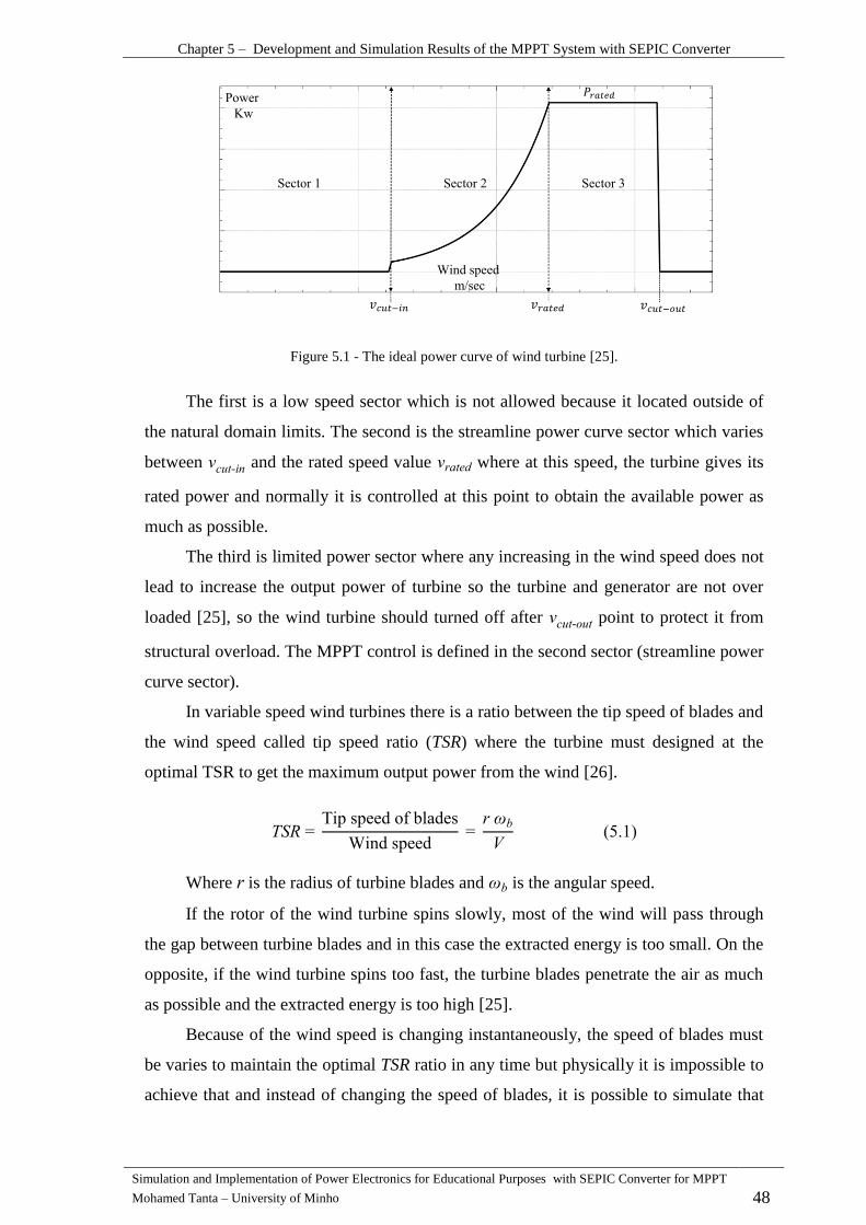
Chapter 5 – Development and Simulation Results of the MPPT System with SEPIC Converter
Simulation and Implementation of Power Electronics for Educational Purposes with SEPIC Converter for MPPT
Mohamed Tanta – University of Minho 48
Figure 5.1 - The ideal power curve of wind turbine [25].
The first is a low speed sector which is not allowed because it located outside of
the natural domain limits. The second is the streamline power curve sector which varies
between - and the rated speed value where at this speed, the turbine gives its
rated power and normally it is controlled at this point to obtain the available power as
much as possible.
The third is limited power sector where any increasing in the wind speed does not
lead to increase the output power of turbine so the turbine and generator are not over
loaded [25], so the wind turbine should turned off after - point to protect it from
structural overload. The MPPT control is defined in the second sector (streamline power
curve sector).
In variable speed wind turbines there is a ratio between the tip speed of blades and
the wind speed called tip speed ratio (TSR) where the turbine must designed at the
optimal TSR to get the maximum output power from the wind [26].
Tip speed of blades
Wind speed
Where is the radius of turbine blades and is the angular speed.
If the rotor of the wind turbine spins slowly, most of the wind will pass through
the gap between turbine blades and in this case the extracted energy is too small. On the
opposite, if the wind turbine spins too fast, the turbine blades penetrate the air as much
as possible and the extracted energy is too high [25].
Because of the wind speed is changing instantaneously, the speed of blades must
be varies to maintain the optimal TSR ratio in any time but physically it is impossible to
achieve that and instead of changing the speed of blades, it is possible to simulate that

Chapter 5 – Development and Simulation Results of the MPPT System with SEPIC Converter
Simulation and Implementation of Power Electronics for Educational Purposes with SEPIC Converter for MPPT
Mohamed Tanta – University of Minho 49
by changing the duty cycle of the DC-DC converter (increase or decrease the load of
wind turbine) which already included inside the micro wind energy system.
There are three main equations to describe the wind turbine system which are the
mechanical power, the mechanical torque and the tip speed ratio equation [26].
Where the is a power coefficient.
: is a Pitch angle of power turbine blades, is a gear ratio between the turbine
shaft and the generator rotor shaft.
The governing equation for the wind turbine ( ) is the main
equation which describe the power coefficient as a function with tip speed ratio and the
pitch angle for the blade and given as:
By supposing the pitch angle equal to zero
(
i ) e
i
By giving different values of TSR, the governing equation simulation results as in
the Figure 5.2 [26].
Figure 5.2 - Power coefficient curve as a function with TSR ( ).

Chapter 5 – Development and Simulation Results of the MPPT System with SEPIC Converter
Simulation and Implementation of Power Electronics for Educational Purposes with SEPIC Converter for MPPT
Mohamed Tanta – University of Minho 50
The micro wind power must work at optimal power curve which is the maximum
point of every mechanical power – speed characteristics (with fixed pitch angle). These
curves change according to linear speed value as shown in Figure 5.3 [26].
Figure 5.3 - Mechanical power – speed characteristics.
To convert the wind energy into mechanical energy and then to obtain electrical
energy, a micro wind generator (SilentWind) is used as shown in Figure 5.4. This
generator has small dimensions and ready to use in small applications such as boats,
caravans, recreational vehicles, telecommunications, etc. This synchronous permanent
magnet generator in Figure 5.5 has a maximum power 450 W and rated voltage 24 V.
This wind turbine has the following characteristics to determine the work limits and the
range of wind speed as shown in the Table 5.1 (electrical specifications) and Table 5.2
(mechanical specifications).
Figure 5.4 - SilentWind micro wind turbine [27].
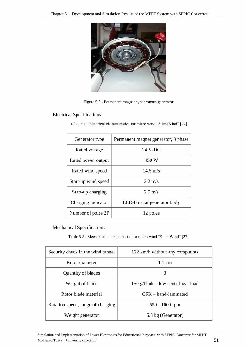
Chapter 5 – Development and Simulation Results of the MPPT System with SEPIC Converter
Simulation and Implementation of Power Electronics for Educational Purposes with SEPIC Converter for MPPT
Mohamed Tanta – University of Minho 51
Figure 5.5 - Permanent magnet synchronous generator.
Electrical Specifications:
Table 5.1 - Electrical characteristics for micro wind “SilentWind” [27].
Generator type Permanent magnet generator, 3 phase
Rated voltage 24 V-DC
Rated power output 450 W
Rated wind speed 14.5 m/s
Start-up wind speed 2.2 m/s
Start-up charging 2.5 m/s
Charging indicator LED-blue, at generator body
Number of poles 2P 12 poles
Mechanical Specifications:
Table 5.2 - Mechanical characteristics for micro wind “SilentWind” [27].
Security check in the wind tunnel 122 km/h without any complaints
Rotor diameter 1.15 m
Quantity of blades 3
Weight of blade 150 g/blade - low centrifugal load
Rotor blade material CFK – hand-laminated
Rotation speed, range of charging 550 - 1600 rpm
Weight generator 6.8 kg (Generator)
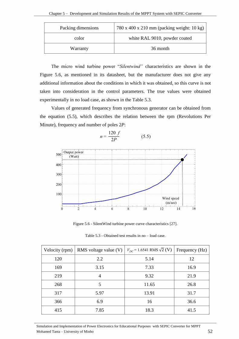
Chapter 5 – Development and Simulation Results of the MPPT System with SEPIC Converter
Simulation and Implementation of Power Electronics for Educational Purposes with SEPIC Converter for MPPT
Mohamed Tanta – University of Minho 52
Packing dimensions 780 x 400 x 210 mm (packing weight: 10 kg)
color white RAL 9010, powder coated
Warranty 36 month
The micro wind turbine power “ l ” characteristics are shown in the
Figure 5.6, as mentioned in its datasheet, but the manufacturer does not give any
additional information about the conditions in which it was obtained, so this curve is not
taken into consideration in the control parameters. The true values were obtained
experimentally in no load case, as shown in the Table 5.3.
Values of generated frequency from synchronous generator can be obtained from
the equation (5.5), which describes the relation between the rpm (Revolutions Per
Minute), frequency and number of poles 2P:
Figure 5.6 - SilentWind turbine power curve characteristics [27].
Table 5.3 - Obtained test results in no – load case.
Velocity (rpm) RMS voltage value (V) RMS √ (V) Frequency (Hz)
120 2.2 5.14 12
169 3.15 7.33 16.9
219 4 9.32 21.9
268 5 11.65 26.8
317 5.97 13.91 31.7
366 6.9 16 36.6
415 7.85 18.3 41.5

Chapter 5 – Development and Simulation Results of the MPPT System with SEPIC Converter
Simulation and Implementation of Power Electronics for Educational Purposes with SEPIC Converter for MPPT
Mohamed Tanta – University of Minho 53
464 8.8 20.5 46.4
549 10.3 24 54.9
600 11.36 26.46 60
850 16.5 38.44 85
1000 19 44.2 100
Uncontrolled Three-Phase Rectifier Bridge with Condenser 5.3.
The output voltage wave consists of the tops of the three-phase AC voltage waves
so this voltage will be with a small oscillation and it is possible to solve this problem by
using a capacitive condenser to get a DC voltage as much as possible. According to the
equation, the max value of output DC voltage will be more than the max value of
AC input voltage by 1.6541 factor (without using the condenser).
sin
Practically, it is possible to get uncontrolled three-phase rectifier bridge by using
two single phase bridges. The single-phase bridge that will using here is a GBPC5010
with a condenser F. Figure 5.7 shows how to use two single-phase rectifier
bridges to obtain one three-phase rectifier bridge. Figure 5.8 shows the condenser that
will be used to have DC wave as much as possible.
Figure 5.7 - Using two single-phase rectifiers to obtain three-phase rectifier bridge.
Figure 5.8 - F Condenser.

Chapter 5 – Development and Simulation Results of the MPPT System with SEPIC Converter
Simulation and Implementation of Power Electronics for Educational Purposes with SEPIC Converter for MPPT
Mohamed Tanta – University of Minho 54
SEPIC Converter Design 5.4.
Single Ended Primary Inductance Converter (SEPIC) is very common to use in
PV panels and wind turbines circuits as a voltage regulator because it is capable to work
as a step-up or step-down converter (like Buck-Boost converter) but with more
efficiency and less circuit size.
In this project, coupled inductor SEPIC converter is used here to get more
efficiency and other features. It consists of two coils wound onto one core and has
turn ratio, which leads to generate mutual electromagnetic flux between the
inductors, thus decrease the volume of coils and other active elements. Input voltage of
SEPIC converter is connected with series inductor and the output voltage is connected
with parallel capacitor as shown in Figure 5.9, so SEPIC converter equevalent circuit
has a current source charactaristic at the input side, also it has a voltage source
charactaristic at the output side.
Figure 5.9 - SEPIC converter equivalent circuit.
Work mechanism for this converter is very similar to isolated coils one and the
main equation which gives the average output voltage is:
Average output voltage for this converter could be higher or fewer than the input
voltage depinding on duty cycle value, but it does not invert output voltage polarity.
If output voltage is lower than input voltage.
If output voltage is higher than input voltage.
The benefits of using one coupled inductor instead of using two separated ones
are [28]:
1- The most Important feature is to generate mutual electromagnetic flux
leads to decrease the inductors values DC resistances for inductors can be
Chapter 5 – Development and Simulation Results of the MPPT System with SEPIC Converter
Simulation and Implementation of Power Electronics for Educational Purposes with SEPIC Converter for MPPT
Mohamed Tanta – University of Minho 55
reduced heating losses will decrease increase the efficiency of the
SEPIC.
2- Decrease the inductors values leads to decrease the volume of device
low costs.
3- Because of mutual inductance, the input ripple current will divide between two
inductors input ripple current will decrease using smaller capacitors
values.
For sure, next calculations will suppose continuous work mode of SEPIC to avoid many
problems to appear.
Duty Cycle Values 5.4.1.
The duty cycle of SIPEC is given by the next equations:
Where is a diode voltage dropping.
It is not possible to work with wide duty cycle domain to have a stabilize output
voltage. Therefore, the duty cycle domain must be limited between two values and
according to our application, the output voltage must always be constant with a value
more than battery’s voltage value to activate charging process. The voltage of battery
equals to 12 V so the output voltage for SEPIC is assumed 13 V. The minimum value of
input voltage is 6 V and the maximum value of input voltage is 20 V. Consequently, the
values of and are:
Inductors Values 5.4.2.
The first step of designing PWM switching regulator is to detect the inductor
ripple current to make EMI (Electromagnetic Interference) between the inductors,
where too little value may cause to have unstable PWM operation. The main rule is to
use a factor (m) between of input current with pay attention that it is not
possible to work in the discontinued region [29].

Chapter 5 – Development and Simulation Results of the MPPT System with SEPIC Converter
Simulation and Implementation of Power Electronics for Educational Purposes with SEPIC Converter for MPPT
Mohamed Tanta – University of Minho 56
The worst-case efficiency for the SEPIC.
The charging current for the battery is not constant and it depends on the kind of
battery, for example some batteries have recommended maximum charging current limit
about 2 A and other batteries have other values of charging current about 7 A.
Therefore, the domain of output current will be taken as:
⇒ W ⇒ W
In the coupled coils SEPIC converter, if the coupled coils have the same number
of windings and homogeneous coil, the mutual inductance will force the ripple current
to be divided equally between two coupled inductors, but in real coupled inductor the
inductors do not have exactly the same value so the ripple current will not divided
equally but regardless to that, the values of coupled inductors here are assumed to be
half of separate inductors values [29].
H
It is not available to get an accurate value of inductance as a calculated value so
the real value of coupled inductor equals to H.
The peak value of input side inductor current should be more than the peak value
of output side inductor current as shown in next equations [29].
(
)
To determine the value of mutual inductance firstly, one of both inductors
measured by special device to determine individual characteristics of inductor, after that
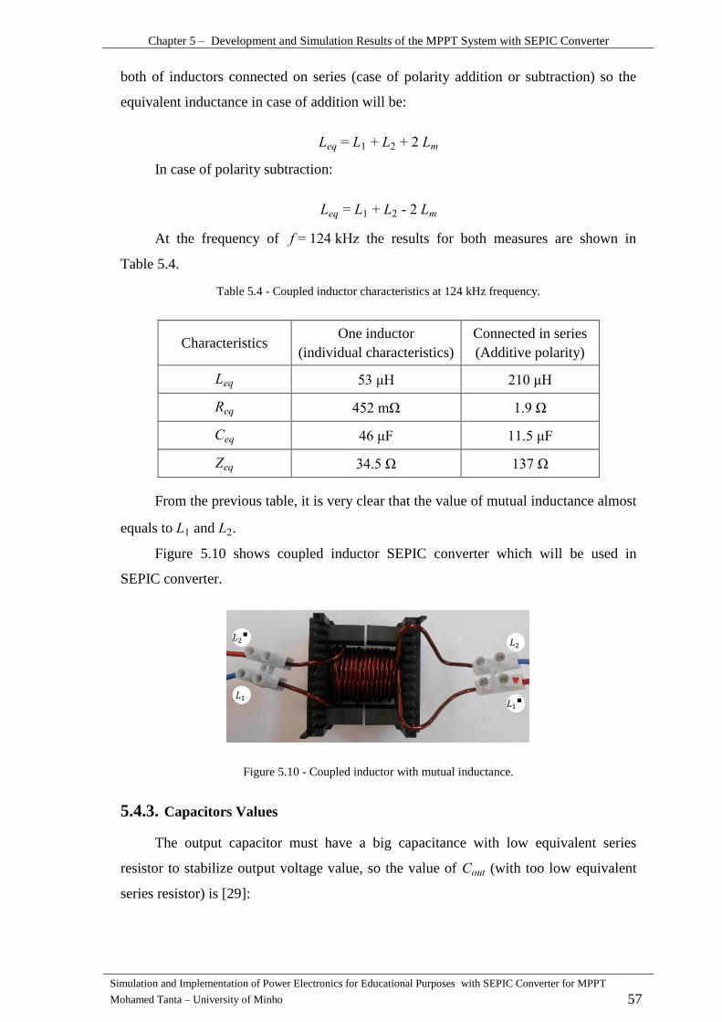
Chapter 5 – Development and Simulation Results of the MPPT System with SEPIC Converter
Simulation and Implementation of Power Electronics for Educational Purposes with SEPIC Converter for MPPT
Mohamed Tanta – University of Minho 57
both of inductors connected on series (case of polarity addition or subtraction) so the
equivalent inductance in case of addition will be:
In case of polarity subtraction:
At the frequency of kHz the results for both measures are shown in
Table 5.4.
Table 5.4 - Coupled inductor characteristics at 124 kHz frequency.
Characteristics One inductor
(individual characteristics)
Connected in series
(Additive polarity)
H H
m
F F
From the previous table, it is very clear that the value of mutual inductance almost
equals to and .
Figure 5.10 shows coupled inductor SEPIC converter which will be used in
SEPIC converter.
Figure 5.10 - Coupled inductor with mutual inductance.
Capacitors Values 5.4.3.
The output capacitor must have a big capacitance with low equivalent series
resistor to stabilize output voltage value, so the value of (with too low equivalent
series resistor) is [29]:

Chapter 5 – Development and Simulation Results of the MPPT System with SEPIC Converter
Simulation and Implementation of Power Electronics for Educational Purposes with SEPIC Converter for MPPT
Mohamed Tanta – University of Minho 58
The difference between the output voltage of SEPI and battery’s voltage should
be less than 1 V so the value of supposed as 0.3 V.
F
The real value of equals to F.
This capacitor must have an RMS current rating more than the RMS load current
value as the next equation [29]:
√
The input capacitor current must be calculated after adding the losses to its value
(dividing on the efficiency ) [29].
√
√
The ripple voltage across is:
By supposing V in in F
Selection of Active Components 5.4.4.
The current rating for the MOSFET must selected carefully because this value
will determine the maximum output current for the SEPIC [29].
At the moderate temperature, MOSFET losses is given by the next equation [29]:
l ( ) [ ( )]
Where is the resistor of Drain-Source junction in turn-on case.
Where the RMS MOSFET current value is [29]:
√
The diode must carry same value of MOSFET current so:

Chapter 5 – Development and Simulation Results of the MPPT System with SEPIC Converter
Simulation and Implementation of Power Electronics for Educational Purposes with SEPIC Converter for MPPT
Mohamed Tanta – University of Minho 59
STTH30R06W power diode will be used here with average forward current
equals to 30 A.
IRFB4110PbF power MOSFET will be used here also.
Figure 5.11 shows the implemented circuit of coupled inductor SEPIC converter.
Figure 5.11 - Implemented circuit of SEPIC converter.
1- Output capacitor F.
2- Input capacitor F
3- IRFB4110PbF power MOSFET.
4- STTH30R06W power diode.
5- Output voltage divider pins.
6- Protection fuses.
7- Gate – ground MOSFET pins.
8- MOSFET protecting and driving circuit.
9- Input source pin.
10- polar pin.
11- normal pin.
12- Load pin.
13- Ground pins.
14- Output voltage divider.
Control Process 5.5.
To drive the SEPI PWM pulses must applied on the MOSFET’s gate with
varies duty cycle according to the input voltage of the SEPIC (the output of rectifier).
The microcontroller (ATMEGA UNO 328P) tasks are:
15

Chapter 5 – Development and Simulation Results of the MPPT System with SEPIC Converter
Simulation and Implementation of Power Electronics for Educational Purposes with SEPIC Converter for MPPT
Mohamed Tanta – University of Minho 60
1- Generate PWM pulses with the possibility of change duty cycle value.
2- Read the input voltage value and change the duty cycle magnitude according to
this value.
3- Applying the MPPT control process of all system.
ATMEGA UNO 328P microcontroller will be used in this project from Atmel
manufacturer, where the ATMEGA family characterized by simple programming and the
possibility of programming in several languages like C+ and Assembly.
The microcontroller board is shown in the Figure 5.12.
Figure 5.12 - ATMEGA UNO 328P board [30].
1- External USB plug.
2- External power supply.
3- ATMEGA 328P microcontroller ship.
4- Microcontroller crystal which gives the clock frequency 16 000 kHz.
5- Reset button.
6- Power on detector.
7- Serial in and serial out detectors.
8- Processor detector.
9- In-circuit serial programmer (ICSP).
10- 5 V and 3.3 V Power supplies pins with grounded pins.
11- Analog pins for analog to digital converter (ADC).
12- Serial in or receive information detector (RX) and serial out or sending
information detector (TX).
13- Digital input/output pins (some of pins have PWM output).
14- Ground pin and analog reference pin (normally 5 V) for ADC.
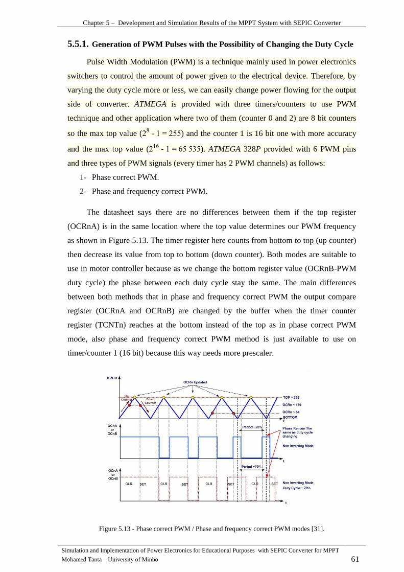
Chapter 5 – Development and Simulation Results of the MPPT System with SEPIC Converter
Simulation and Implementation of Power Electronics for Educational Purposes with SEPIC Converter for MPPT
Mohamed Tanta – University of Minho 61
Generation of PWM Pulses with the Possibility of Changing the Duty Cycle 5.5.1.
Pulse Width Modulation (PWM) is a technique mainly used in power electronics
switchers to control the amount of power given to the electrical device. Therefore, by
varying the duty cycle more or less, we can easily change power flowing for the output
side of converter. ATMEGA is provided with three timers/counters to use PWM
technique and other application where two of them (counter 0 and 2) are 8 bit counters
so the max top value ( - ) and the counter 1 is 16 bit one with more accuracy
and the max top value ( - ). ATMEGA 328P provided with 6 PWM pins
and three types of PWM signals (every timer has 2 PWM channels) as follows:
1- Phase correct PWM.
2- Phase and frequency correct PWM.
The datasheet says there are no differences between them if the top register
(OCRnA) is in the same location where the top value determines our PWM frequency
as shown in Figure 5.13. The timer register here counts from bottom to top (up counter)
then decrease its value from top to bottom (down counter). Both modes are suitable to
use in motor controller because as we change the bottom register value (OCRnB-PWM
duty cycle) the phase between each duty cycle stay the same. The main differences
between both methods that in phase and frequency correct PWM the output compare
register (OCRnA and OCRnB) are changed by the buffer when the timer counter
register (TCNTn) reaches at the bottom instead of the top as in phase correct PWM
mode, also phase and frequency correct PWM method is just available to use on
timer/counter 1 (16 bit) because this way needs more prescaler.
Figure 5.13 - Phase correct PWM / Phase and frequency correct PWM modes [31].

Chapter 5 – Development and Simulation Results of the MPPT System with SEPIC Converter
Simulation and Implementation of Power Electronics for Educational Purposes with SEPIC Converter for MPPT
Mohamed Tanta – University of Minho 62
3- Fast PWM mode.
This way could generate the highest PWM frequency comparing with the other
PWM methods as shown in Figure 5.14 and because of the MOSFET needs high work
frequency, so this PWM type is suitable for our application and possible to use with
timer/counter 1 (16 bit) and timer/counter 0 or timer/counter 2 (8 bit). The timer/counter
register here will just count from bottom to top (up counter).
According to our application and before start programming, the following points
must be considered [32]:
1- The PWM operation mode.
2- The timer/counter which is necessary to use (number of bits).
3- Prescaler value.
Because of our application here requires high work frequency, so the PWM
operation mode should be fast PWM mode and it is possible to achieve that by using
any timer/counter. The timer/counter 2 will be used here with varies top register values.
The prescaler factor N here takes one of these values (1, 8, 64, 256, or 1024) and closely
linked with the PWM frequency value, clock frequency and decimal value of top
register (OCR2A) which equals to ( ). PWM frequency equation is given by:
l
The value of prescaler factor N here is defined as 1 to obtain the highest frequency
and that achieved by activate (CS20) register, In this case the highest PWM frequency
will be:
kHz
kHz
In case of more PWM frequency is required, the decimal value of top register
must be less than 256. It should be clear now that to generate a PWM frequency more
than 62.5 kHz we should sacrifice the duty cycle resolution and to achieve that, the
value of the register (OCR2A) which define the top value must be less than 256
according to the required PWM frequency value. This choice can be achieved by
activate the bits (WGM20) and (WGM21) on (TCCR2A) register and activate the bit
(WGM22) on (TCCR2B) register as shown in Table 5.5.
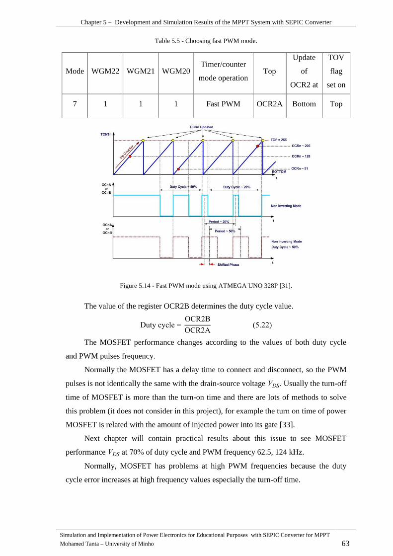
Chapter 5 – Development and Simulation Results of the MPPT System with SEPIC Converter
Simulation and Implementation of Power Electronics for Educational Purposes with SEPIC Converter for MPPT
Mohamed Tanta – University of Minho 63
Table 5.5 - Choosing fast PWM mode.
Mode WGM22 WGM21 WGM20 Timer/counter
mode operation Top
Update
of
OCR2 at
TOV
flag
set on
7 1 1 1 Fast PWM OCR2A Bottom Top
Figure 5.14 - Fast PWM mode using ATMEGA UNO 328P [31].
The value of the register OCR2B determines the duty cycle value.
uty cycle O R
O R
The MOSFET performance changes according to the values of both duty cycle
and PWM pulses frequency.
Normally the MOSFET has a delay time to connect and disconnect, so the PWM
pulses is not identically the same with the drain-source voltage . Usually the turn-off
time of MOSFET is more than the turn-on time and there are lots of methods to solve
this problem (it does not consider in this project), for example the turn on time of power
MOSFET is related with the amount of injected power into its gate [33].
Next chapter will contain practical results about this issue to see MOSFET
performance at of duty cycle and PWM frequency 62.5, 124 kHz.
Normally, MOSFET has problems at high PWM frequencies because the duty
cycle error increases at high frequency values especially the turn-off time.

Chapter 5 – Development and Simulation Results of the MPPT System with SEPIC Converter
Simulation and Implementation of Power Electronics for Educational Purposes with SEPIC Converter for MPPT
Mohamed Tanta – University of Minho 64
Read the Input Voltage / Current Values (ADC) 5.5.2.
ADC (Analog to Digital Converter) gives us the possibility to convert analog
voltage to digital one and read voltage values from sensors like temperature, humidity
and pressure sensors for many applications.
ATMEGA family are provided with analog to digital converter which ready to use
with maximum 10 bits resolution (
and that means the input ADC voltage
(analog voltage) will be converted to a decimal value between 0 and 1023. In addition,
ATMEGA 328P is provided with 6 ADC input pins (PORT C pins) but the
microcontroller can only do one ADC conversion in the same time, so between ADC
conversion process, there is an analogic multiplexer which allow for us to select the
ADC pin that we want to read. In the other words, it is possible to read one ADC value
from all 6 ADC pins at the same time.
The analog input pins can read the input analog voltage from V so the 5 V
value equals to 1023 numeric if the AREF (pin 21) is connected with 5 V source pin and
in this case the resolution will be 5 V/1023 = 4.88 mV for each value.
The internal ADC can also be used in 8 bits but that leads to decrease the ADC
resolution and reducing the time which need to complete the conversion process. The 8
bits ADC is useful to use in case of using more than 3 ADC channels.
In our project, two 10 bits ADC channels for voltage and current with 5 V
reference was used.
Also, one of ADC characteristics is an ADC frequency where any increasing in
this value leads to decrease ADC prescaler (as in PWM process).
ecause of this project depends on change MOSFET’s duty cycle according to
SEPIC input voltage, the ADC reader and value must have high prescaler as much as
possible, so high ADC prescaler value was used here (equals to 128) with 10 bits ADC
resolution. Consequently, The ADC frequency will be:
l
prescaler
kHz
kHz
The ADC prescaler is defined from the (ADCSRA) register and the bits (ADSP0,
ADSP1, ADSP2).

Chapter 5 – Development and Simulation Results of the MPPT System with SEPIC Converter
Simulation and Implementation of Power Electronics for Educational Purposes with SEPIC Converter for MPPT
Mohamed Tanta – University of Minho 65
MOSFET Driving Circuit 5.6.
The pulses which are applied on MOSFET’s gate should be provided with high
power density. Therefore, this circuit contains many elements to provide the PWM
signals in high efficiency as much as possible. These elements are voltage isolation
elements and gate drive optocoupler to achieve an optical isolation between the
microcontroller and MOSFET’s gate as shown in Figure 5.16.
To ensure safe operation range for MOSFET, two Zener diodes are using to limit
the voltage level between gate pin and source pin, so from MOSFET’s datasheet, the
absolute maximum rating of gate to source voltage equal to 40 V in repetitively case, so
the voltage must not be more than 40 V otherwise the MOSFET will damage.
By using two Zener, the voltage will be 30 V as shown in Figure 5.15.
Figure 5.15 - Optical isolation between microcontroller and gate to ground circuit.
Figure 5.16 - MOSFET driving circuit.
MPPT Control Algorithm 5.7.
The using of a Maximum Power Point Tracker (MPPT) means that the charging
system always work in the maximum power point, and to achieve that, the wind turbine
speed must be determined at specific speed but the wind speed is always changing
instantaneously, so it is almost impossible to make a controlling in wind turbine speed.
Because of changing wind turbine speed is very hard to define the MPPT, the duty
cycle of DC-DC converter (SEPIC converter) must varies according to the wind turbine
speed until reaching for the maximum power point regardless of the load value. by other

Chapter 5 – Development and Simulation Results of the MPPT System with SEPIC Converter
Simulation and Implementation of Power Electronics for Educational Purposes with SEPIC Converter for MPPT
Mohamed Tanta – University of Minho 66
words, this way depends on changing the equivalent load value for whole system
(SEPIC duty cycle) regardless of wind speed value.
In general, there are two different ways to do MPPT control. The first one is an
optimal torque control (OTC) which founded to be the best MPPT control method [25].
The second method which is used here is a perturbation and observation (P&O)
method that is a very simple mathematical technique to implement but with less
efficiency comparing with OTC method [25].
The main task for this method is to search about optimal point of power curve by
create a control variable in a small step size to increment or decrement the power
according to the location of operating point. If the operating point is located on the left
of the optimal power point, the control variable should make a shifting for operating
point in right direction and vice versa as shown in Figure 5.17.
Figure 5.17 - MPPT perturbation and observation control method [25].
The step size of the control variable should not be large to get the optimal power
point and get more efficiency as much as possible. Otherwise, the operating point will
oscillate around the optimal power point with faster response and the system will not
work at MPPT point (unstable work) [34].
The main feature for P&O method that it could be implemented without knowing
any information about wind characteristics curve. However, this method is not suitable
for rapid wind variation system because it does not give the optimal power point at
rapid wind variation.
The MPPT (P&O method) flowchart is as shown in the Figure 5.18 where K is a
duty cycle value, is an instantaneous power value, is an average power value
and - is a previous average power value.
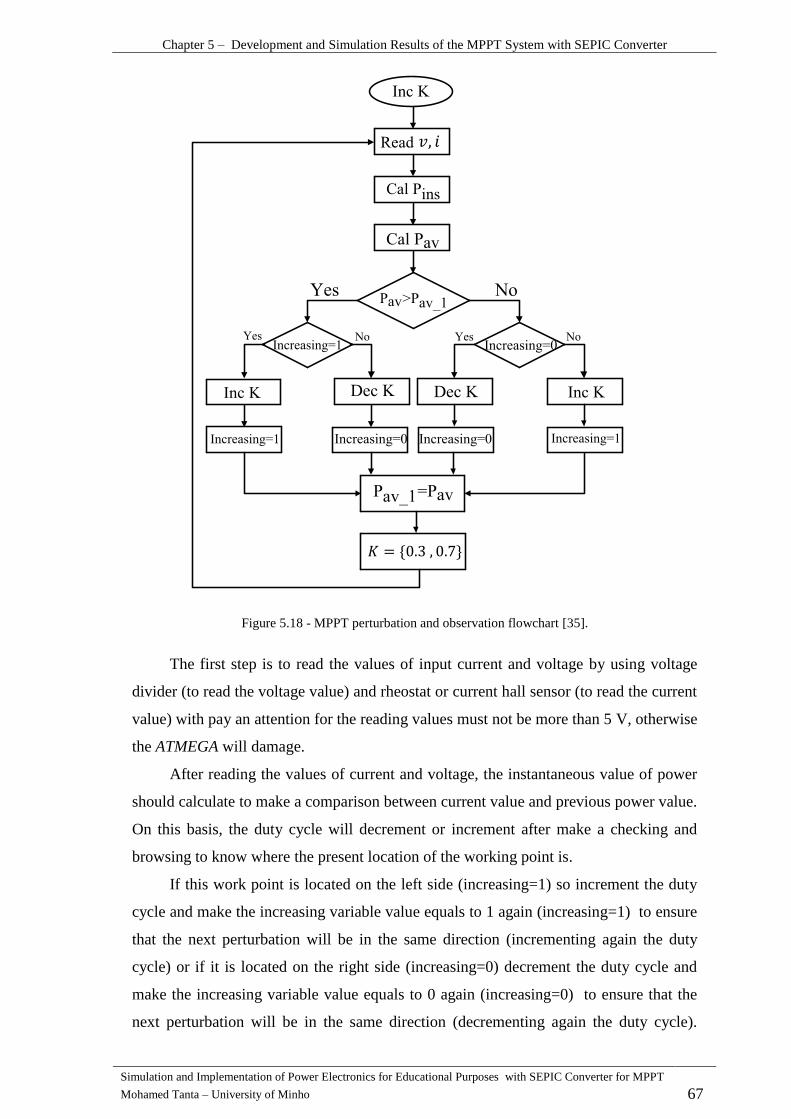
Chapter 5 – Development and Simulation Results of the MPPT System with SEPIC Converter
Simulation and Implementation of Power Electronics for Educational Purposes with SEPIC Converter for MPPT
Mohamed Tanta – University of Minho 67
Figure 5.18 - MPPT perturbation and observation flowchart [35].
The first step is to read the values of input current and voltage by using voltage
divider (to read the voltage value) and rheostat or current hall sensor (to read the current
value) with pay an attention for the reading values must not be more than 5 V, otherwise
the ATMEGA will damage.
After reading the values of current and voltage, the instantaneous value of power
should calculate to make a comparison between current value and previous power value.
On this basis, the duty cycle will decrement or increment after make a checking and
browsing to know where the present location of the working point is.
If this work point is located on the left side (increasing=1) so increment the duty
cycle and make the increasing variable value equals to 1 again (increasing=1) to ensure
that the next perturbation will be in the same direction (incrementing again the duty
cycle) or if it is located on the right side (increasing=0) decrement the duty cycle and
make the increasing variable value equals to 0 again (increasing=0) to ensure that the
next perturbation will be in the same direction (decrementing again the duty cycle).
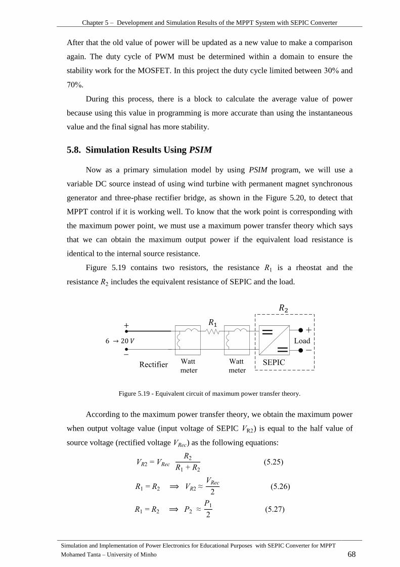
Chapter 5 – Development and Simulation Results of the MPPT System with SEPIC Converter
Simulation and Implementation of Power Electronics for Educational Purposes with SEPIC Converter for MPPT
Mohamed Tanta – University of Minho 68
After that the old value of power will be updated as a new value to make a comparison
again. The duty cycle of PWM must be determined within a domain to ensure the
stability work for the MOSFET. In this project the duty cycle limited between and
.
During this process, there is a block to calculate the average value of power
because using this value in programming is more accurate than using the instantaneous
value and the final signal has more stability.
Simulation Results Using PSIM 5.8.
Now as a primary simulation model by using PSIM program, we will use a
variable DC source instead of using wind turbine with permanent magnet synchronous
generator and three-phase rectifier bridge, as shown in the Figure 5.20, to detect that
MPPT control if it is working well. To know that the work point is corresponding with
the maximum power point, we must use a maximum power transfer theory which says
that we can obtain the maximum output power if the equivalent load resistance is
identical to the internal source resistance.
Figure 5.19 contains two resistors, the resistance is a rheostat and the
resistance includes the equivalent resistance of SEPIC and the load.
Figure 5.19 - Equivalent circuit of maximum power transfer theory.
According to the maximum power transfer theory, we obtain the maximum power
when output voltage value (input voltage of SEPIC R ) is equal to the half value of
source voltage (rectified voltage ) as the following equations:

Chapter 5 – Development and Simulation Results of the MPPT System with SEPIC Converter
Simulation and Implementation of Power Electronics for Educational Purposes with SEPIC Converter for MPPT
Mohamed Tanta – University of Minho 69
By applying variable DC voltage V as a rectified voltage and gives the
value of , In this case the system will work almost at
optimal power point and the extracted power from the source is almost a maximum.
MPPT work mechanism does not related to SEPI ’s load value Therefore,
changing the value of this load does not change the final result of MPPT.
Simulation results for primary simulation model that shown in Figure 5.20 are
shown in the Figure 5.21 where the equations and are applied here by
choosing the increment step value equals to 2.
Figure 5.20 - Primary simulation model to test MPPT control.
Now after make a confirmation about MPPT control method in case of passive
load, a micro wind turbine with permanent magnet synchronous generator and
uncontrolled three-phase rectifier bridge will be added for the primary simulation model
in Figure 5.20. The rectifier bridge will followed by a condenser 1400 F to decrease
the ripples as much as possible and the input resistance will be removed. New
simulation model will contain also all previous components and 12 V battery in the
output to test charging process.
The micro wind turbine and permanent magnet synchronous generator
characteristics in PSIM were considered as shown in the Table 5.6.
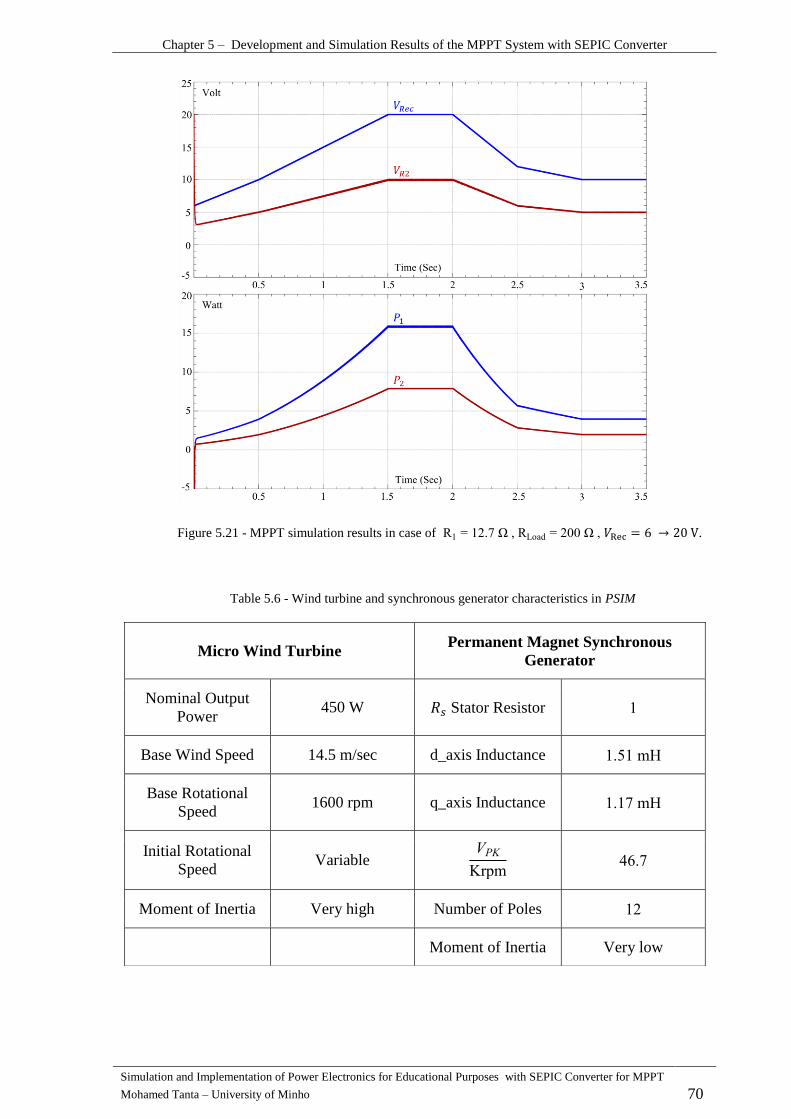
Chapter 5 – Development and Simulation Results of the MPPT System with SEPIC Converter
Simulation and Implementation of Power Electronics for Educational Purposes with SEPIC Converter for MPPT
Mohamed Tanta – University of Minho 70
Micro Wind Turbine Permanent Magnet Synchronous
Generator
Nominal Output
Power 450 W Stator Resistor
Base Wind Speed 14.5 m/sec d_axis Inductance mH
Base Rotational
Speed 1600 rpm q_axis Inductance mH
Initial Rotational
Speed Variable
Krpm
Moment of Inertia Very high Number of Poles
Moment of Inertia Very low
Table 5.6 - Wind turbine and synchronous generator characteristics in PSIM
Figure 5.21 - MPPT simulation results in case of R Ω RLoad Ω 𝑉Rec 6 V.
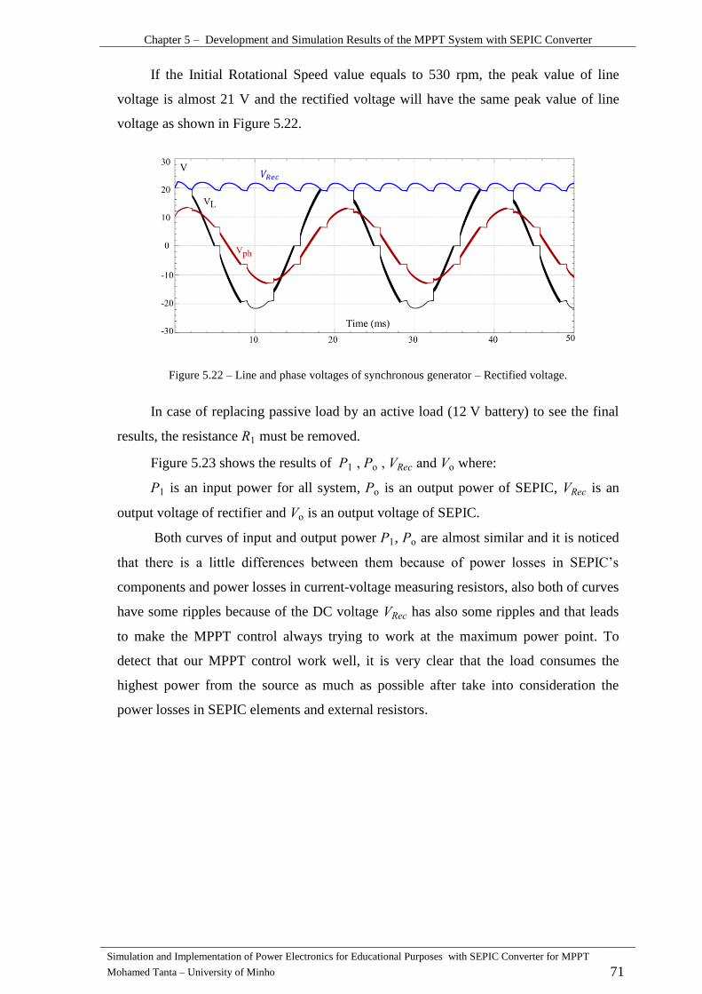
Chapter 5 – Development and Simulation Results of the MPPT System with SEPIC Converter
Simulation and Implementation of Power Electronics for Educational Purposes with SEPIC Converter for MPPT
Mohamed Tanta – University of Minho 71
If the Initial Rotational Speed value equals to 530 rpm, the peak value of line
voltage is almost 21 V and the rectified voltage will have the same peak value of line
voltage as shown in Figure 5.22.
Figure 5.22 – Line and phase voltages of synchronous generator – Rectified voltage.
In case of replacing passive load by an active load (12 V battery) to see the final
results, the resistance must be removed.
Figure 5.23 shows the results of o and o where:
is an input power for all system, o is an output power of SEPIC, is an
output voltage of rectifier and o is an output voltage of SEPIC.
Both curves of input and output power , o are almost similar and it is noticed
that there is a little differences between them because of power losses in SEPI ’s
components and power losses in current-voltage measuring resistors, also both of curves
have some ripples because of the DC voltage has also some ripples and that leads
to make the MPPT control always trying to work at the maximum power point. To
detect that our MPPT control work well, it is very clear that the load consumes the
highest power from the source as much as possible after take into consideration the
power losses in SEPIC elements and external resistors.
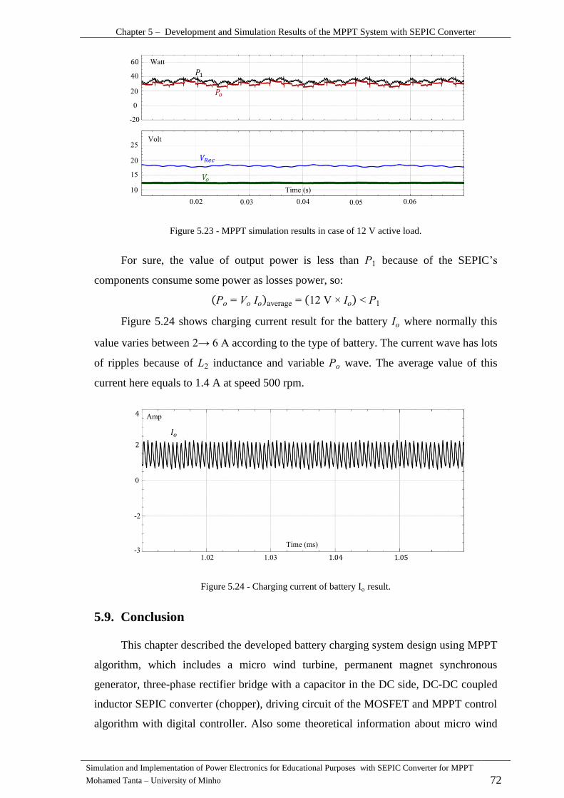
Chapter 5 – Development and Simulation Results of the MPPT System with SEPIC Converter
Simulation and Implementation of Power Electronics for Educational Purposes with SEPIC Converter for MPPT
Mohamed Tanta – University of Minho 72
Figure 5.23 - MPPT simulation results in case of 12 V active load.
For sure, the value of output power is less than because of the SEPIC’s
components consume some power as losses power, so:
average V
Figure 5.24 shows charging current result for the battery where normally this
value varies between according to the type of battery. The current wave has lots
of ripples because of inductance and variable wave. The average value of this
current here equals to 1.4 A at speed 500 rpm.
Figure 5.24 - Charging current of battery Io result.
Conclusion 5.9.
This chapter described the developed battery charging system design using MPPT
algorithm, which includes a micro wind turbine, permanent magnet synchronous
generator, three-phase rectifier bridge with a capacitor in the DC side, DC-DC coupled
inductor SEPIC converter (chopper), driving circuit of the MOSFET and MPPT control
algorithm with digital controller. Also some theoretical information about micro wind
-

Chapter 5 – Development and Simulation Results of the MPPT System with SEPIC Converter
Simulation and Implementation of Power Electronics for Educational Purposes with SEPIC Converter for MPPT
Mohamed Tanta – University of Minho 73
turbine characteristics, like TSR (Tip Speed Ratio) and ideal curve of wind turbine were
explained.
The design calculations for SEPIC converter and other components are described
in this chapter and applied on PSIM simulation model. In addition, the MPPT control
flowchart (perturbation and observation MPPT) using ATMEGA UNO 328P was
described with ADC and PWM processes.
Finally, simulation results showed the MPPT control results, where the maximum
power transfer theory was achieved to work in optimal power point and obtain the
maximum power as much as possible in case of passive load (resistor). In addition, it
was noticed that in case of active load (battery) the maximum power transfer theory and
MPPT control were achieved and both curves of , o are almost similar if the power
losses in SEPI ’s components and current-voltage measuring resistors are taken into
consideration.

Simulation and Implementation of Power Electronics for Educational Purposes - with SEPIC Converter for MPPT
Mohamed Tanta – University of Minho 75
CHAPTER 6
ExperimentalResultsoftheMPPTSystemwithSEPIC
Converter
Introduction 6.1.
This chapter presents the experimental results of the MPPT system for micro wind
power using coupled inductor SEPIC converter in case of passive (resistive) and active
load (battery), which have already presented in chapter 5 as simulation results.
Normally in engineering field, simulation results are different from and nearby
implementation ones for many reasons, like changing in MOSFET response at different
PWM work frequencies, inaccurate simulation parameters values and measurement
errors. Therefore, this chapter will describe these differences and their causes.
Most of the simulation parameters that were introduced in the Chapter 5(SEPIC
parameters, PWM signal properties, MPPT control flowchart) will be taken into account
in this chapter without any changes.
MOSFET Switching Response 6.2.
The switching power losses of MOSFET becomes a major factor in the total
power losses of PE components especially when the PWM frequency being increased to
decrease the total volume of passive equipment. In reality, power MOSFET switching
frequency is limited by reverse recovery losses of body diode more than turn-on / turn-
off time speed, where both of those effects give a poor performance of power MOSFET
and lead to decrease the conversion efficiency [36].
Poor performance of power MOSFET is related with high PWM frequency, low
PWM amplitude and duty cycle value. Therefore, the value of PWM switching
frequency is closely related with the value of duty cycle and turn-on / turn-off time
speed where these times must be less than the half cycle of PWM signal to give the
ability for power MOSFET to switch from on-state to off-state and vice versa.
Consequently, duty cycle value of power MOSFET in this project was bounded between
30% and 70%.

Chapter 6 – Implementation Results of MPPT System for Micro Wind Power Using SEPIC Converter
Simulation and Implementation of Power Electronics for Educational Purposes with SEPIC Converter for MPPT
Mohamed Tanta – University of Minho 76
For previous purposes, MOSFET driving circuit was used in this project to get
high PWM amplitude (about 15 V) and makes isolation between microcontroller board
and MOSFET’s gate circuit
Normally, power MOSFET and body diode losses are [37]:
1- Conduction losses which related with the drain-source resistor in on state.
2- Switching losses which related with turn-on delay time, turn-off delay time, rise
time, fall time and reverse recovery time of body diode.
All of implementation results waveforms were visualized in YOKOGAWA digital
oscilloscope as shown in Figure 6.1.
Figure 6.1 - YOKOGAWA digital oscilloscope.
The following results in Figure 6.2 shows MOSFET’s response at different PWM
frequencies kHz kHz , 70% of duty cycle and 15 V PWM amplitude.
It is clear that at the frequency 123 kHz, the cycle period T is less than in case
62.5 kHz and that leads to decrease MOSFET’s capability to change its work situation
(on-off), so to work at high frequency, fast switching MOSFET with small turn-
on / turn-off time speed must be used. Therefore, the frequency of 62.5 kHz was
adopted in this project because it is more preferable to use and gives spacious domain of
reliability.
Also, some distortions are founded in drain to source voltage signal when
switching frequency equals to 123 kHz as shown in the Figure 6.2.
It is very difficult and complex to simulate MOSFET’s response state in simulation
programs because of non-linear equations and characteristics of MOSFET. Therefore,
these results did not presented in chapter 5 as simulation results [38].
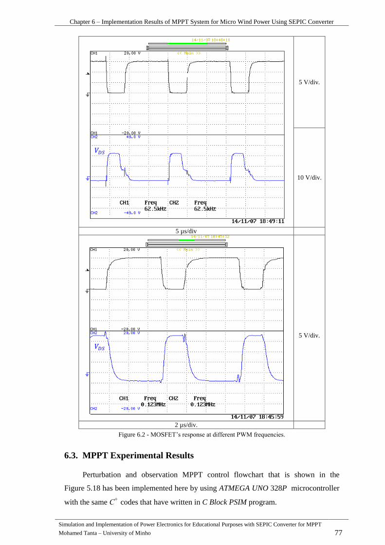
Chapter 6 – Implementation Results of MPPT System for Micro Wind Power Using SEPIC Converter
Simulation and Implementation of Power Electronics for Educational Purposes with SEPIC Converter for MPPT
Mohamed Tanta – University of Minho 77
5 V/div.
10 V/div.
5 µs/div
5 V/div.
2 µs/div.
Figure 6.2 - MOSFET’s response at different PWM frequencies
MPPT Experimental Results 6.3.
Perturbation and observation MPPT control flowchart that is shown in the
Figure 5.18 has been implemented here by using ATMEGA UNO 328P microcontroller
with the same
codes that have written in C Block PSIM program.

Chapter 6 – Implementation Results of MPPT System for Micro Wind Power Using SEPIC Converter
Simulation and Implementation of Power Electronics for Educational Purposes with SEPIC Converter for MPPT
Mohamed Tanta – University of Minho 78
At first, confirmation process for primary simulation model that illustrated in the
Figure 5.20 to test MPPT control in passive load case (resistive load) by using constant
DC voltage as a rectified voltage, then the final results will be taken by using wind
turbine (induction motor controlled by a frequency variator), permanent magnet
synchronous generator, three-phase rectifier bridge and active load (battery).
MPPT Experimental Results by Using Passive Load 6.3.1.
Primary simulation model that is shown in the Figure 5.20 is implemented here
but by using constant DC voltage source equals to 20 V as a rectified voltage. The
values of other components are still the same . we should
remember that, the results of MPPT control did not related with the load value insofar
as related with the increment step value.
In PSIM model, the increment step value was 2 and the sawtooth fast PWM wave
peak value was 100. However, in
codes of ATMEGA UNO the sawtooth fast PWM
wave peak value equals to 255 (8 bit - timer 2) and the increment step value equals to 8.
As in simulation parameters, the increment step value in implementation must be
equals to 5.1 to equivalent this value in simulation which equals to 2, but it was noticed
that to get a good implementation results as shown in the Figure 6.3, the increment step
value must be around 8 where a very low value leads to not reaching to optimal power
point (see the Figure 5.17), also a very high increment step value makes the system
unstable and oscillate around the optimal power point.
If the output power value equals to the half value of the input one, the maximum
power transfer theory will be applied and the extracted power from the source is a
maximum.
We must pay attention that the SEPIC must not work without applying load
otherwise MOSFET’s temperature will increase and damage the MOSFET

Chapter 6 – Implementation Results of MPPT System for Micro Wind Power Using SEPIC Converter
Simulation and Implementation of Power Electronics for Educational Purposes with SEPIC Converter for MPPT
Mohamed Tanta – University of Minho 79
10 V/div.
5 µs/div.
Figure 6.3 - MPPT implementation results by using passive load.
Using ATMEGA UNO 328P to do MPPT control is not very recommended
because it is not a powerful microcontroller comparing with other microcontroller types
like Texas Instrument family, also it has a slow performance and some weaknesses like:
1- In the previous calculations, the increment step value in implementation was
equal to 5.1 but in reality the value should be integer one, otherwise the MPPT
control will take a long time to be applied.
2- In C Block PSIM model, SEPIC input power average value was calculated by
doing 100 calculation steps, but in reality it was 50 steps to compensate the slow
performance of ATMEGA.
MPPT Implementation Results by Using Active Load (Battery) 6.3.2.
The main objective of this project is to implement a battery charging system by
using MPPT system for micro wind power (Silentwind) using SEPIC converter to get
the maximum power at various wind speeds.
At first, and before connect the battery to the system, some steps must be taken
into consideration to increase system protection and avoid any dangerous cases that may
cause damages for the system.
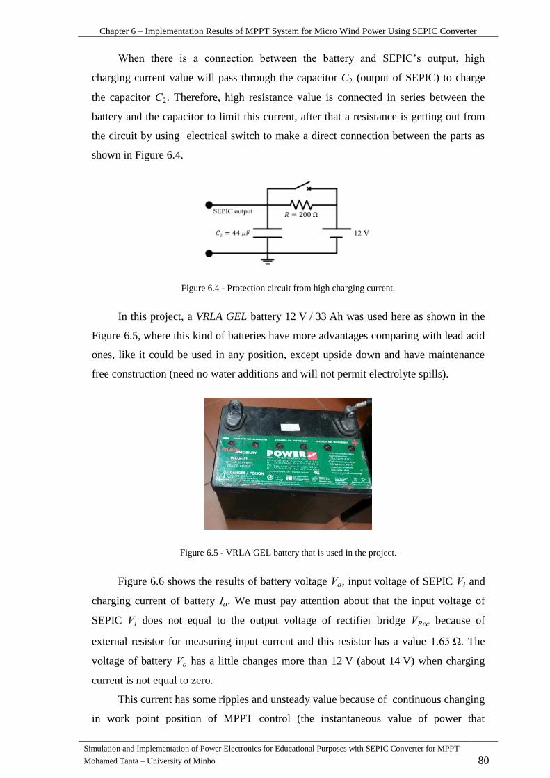
Chapter 6 – Implementation Results of MPPT System for Micro Wind Power Using SEPIC Converter
Simulation and Implementation of Power Electronics for Educational Purposes with SEPIC Converter for MPPT
Mohamed Tanta – University of Minho 80
When there is a connection between the battery and SEPI ’s output high
charging current value will pass through the capacitor (output of SEPIC) to charge
the capacitor . Therefore, high resistance value is connected in series between the
battery and the capacitor to limit this current, after that a resistance is getting out from
the circuit by using electrical switch to make a direct connection between the parts as
shown in Figure 6.4.
Figure 6.4 - Protection circuit from high charging current.
In this project, a VRLA GEL battery 12 V / 33 Ah was used here as shown in the
Figure 6.5, where this kind of batteries have more advantages comparing with lead acid
ones, like it could be used in any position, except upside down and have maintenance
free construction (need no water additions and will not permit electrolyte spills).
Figure 6.5 - VRLA GEL battery that is used in the project.
Figure 6.6 shows the results of battery voltage , input voltage of SEPIC and
charging current of battery . We must pay attention about that the input voltage of
SEPIC does not equal to the output voltage of rectifier bridge because of
external resistor for measuring input current and this resistor has a value . The
voltage of battery has a little changes more than 12 V (about 14 V) when charging
current is not equal to zero.
This current has some ripples and unsteady value because of continuous changing
in work point position of MPPT control (the instantaneous value of power that
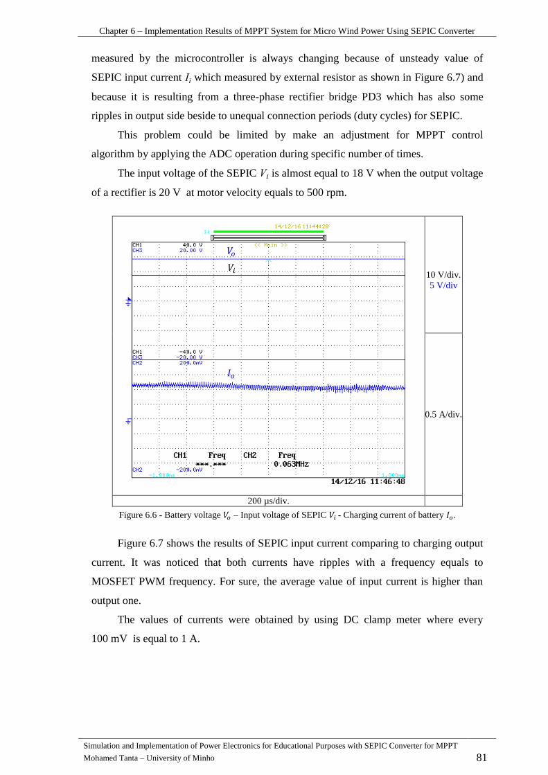
Chapter 6 – Implementation Results of MPPT System for Micro Wind Power Using SEPIC Converter
Simulation and Implementation of Power Electronics for Educational Purposes with SEPIC Converter for MPPT
Mohamed Tanta – University of Minho 81
measured by the microcontroller is always changing because of unsteady value of
SEPIC input current which measured by external resistor as shown in Figure 6.7) and
because it is resulting from a three-phase rectifier bridge PD3 which has also some
ripples in output side beside to unequal connection periods (duty cycles) for SEPIC.
This problem could be limited by make an adjustment for MPPT control
algorithm by applying the ADC operation during specific number of times.
The input voltage of the SEPIC is almost equal to 18 V when the output voltage
of a rectifier is 20 V at motor velocity equals to 500 rpm.
10 V/div.
5 V/div
0.5 A/div.
200 µs/div.
Figure 6.6 - Battery voltage – Input voltage of SEPIC - Charging current of battery .
Figure 6.7 shows the results of SEPIC input current comparing to charging output
current. It was noticed that both currents have ripples with a frequency equals to
MOSFET PWM frequency. For sure, the average value of input current is higher than
output one.
The values of currents were obtained by using DC clamp meter where every
100 mV is equal to 1 A.
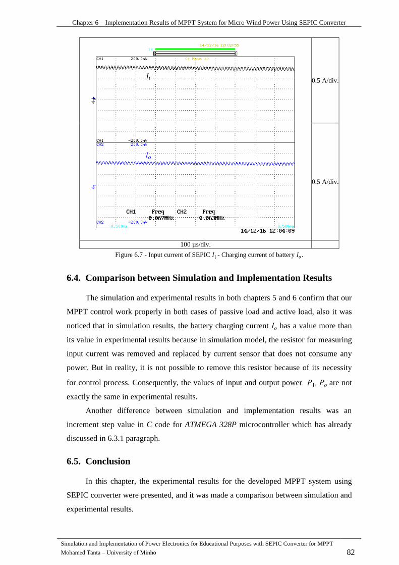
Chapter 6 – Implementation Results of MPPT System for Micro Wind Power Using SEPIC Converter
Simulation and Implementation of Power Electronics for Educational Purposes with SEPIC Converter for MPPT
Mohamed Tanta – University of Minho 82
0.5 A/div.
0.5 A/div.
100 µs/div.
Figure 6.7 - Input current of SEPIC - Charging current of battery .
Comparison between Simulation and Implementation Results 6.4.
The simulation and experimental results in both chapters 5 and 6 confirm that our
MPPT control work properly in both cases of passive load and active load, also it was
noticed that in simulation results, the battery charging current has a value more than
its value in experimental results because in simulation model, the resistor for measuring
input current was removed and replaced by current sensor that does not consume any
power. But in reality, it is not possible to remove this resistor because of its necessity
for control process. Consequently, the values of input and output power are not
exactly the same in experimental results.
Another difference between simulation and implementation results was an
increment step value in C code for ATMEGA 328P microcontroller which has already
discussed in 6.3.1 paragraph.
Conclusion 6.5.
In this chapter, the experimental results for the developed MPPT system using
SEPIC converter were presented, and it was made a comparison between simulation and
experimental results.

Chapter 6 – Implementation Results of MPPT System for Micro Wind Power Using SEPIC Converter
Simulation and Implementation of Power Electronics for Educational Purposes with SEPIC Converter for MPPT
Mohamed Tanta – University of Minho 83
It was noticed that both simulation and experimental results have some variances
because of several factors which are described in this chapter, such as the difference in
increment step value in MPPT algorithm for both results. Also the MOSFET frequency
response in reality is different from its frequency response value in simulation (the
PWM frequency is the same) especially if the temperature of the MOSFET increased
with the time.
Another difference that should not be ignored is the resistor for measuring
input current, which was removed in the simulation model, but in reality, it should be
considered, so to confirm that our MPPT control work as well in reality as in
simulation, the input and output power for SEPIC must be almost the same after taking
the effect of power losses in the input current measuring resistor and in the input voltage
measuring resistors.

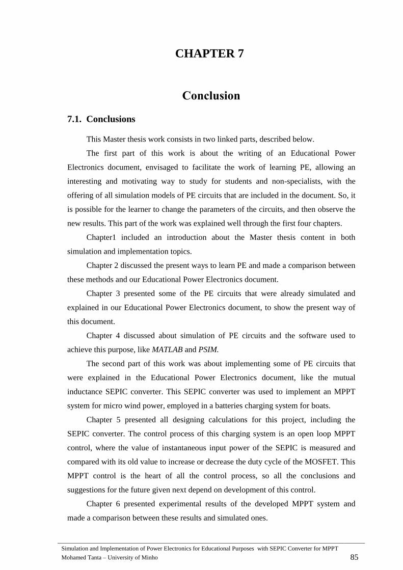
Simulation and Implementation of Power Electronics for Educational Purposes with SEPIC Converter for MPPT
Mohamed Tanta – University of Minho 85
CHAPTER 7
Conclusion
Conclusions 7.1.
This Master thesis work consists in two linked parts, described below.
The first part of this work is about the writing of an Educational Power
Electronics document, envisaged to facilitate the work of learning PE, allowing an
interesting and motivating way to study for students and non-specialists, with the
offering of all simulation models of PE circuits that are included in the document. So, it
is possible for the learner to change the parameters of the circuits, and then observe the
new results. This part of the work was explained well through the first four chapters.
Chapter1 included an introduction about the Master thesis content in both
simulation and implementation topics.
Chapter 2 discussed the present ways to learn PE and made a comparison between
these methods and our Educational Power Electronics document.
Chapter 3 presented some of the PE circuits that were already simulated and
explained in our Educational Power Electronics document, to show the present way of
this document.
Chapter 4 discussed about simulation of PE circuits and the software used to
achieve this purpose, like MATLAB and PSIM.
The second part of this work was about implementing some of PE circuits that
were explained in the Educational Power Electronics document, like the mutual
inductance SEPIC converter. This SEPIC converter was used to implement an MPPT
system for micro wind power, employed in a batteries charging system for boats.
Chapter 5 presented all designing calculations for this project, including the
SEPIC converter. The control process of this charging system is an open loop MPPT
control, where the value of instantaneous input power of the SEPIC is measured and
compared with its old value to increase or decrease the duty cycle of the MOSFET. This
MPPT control is the heart of all the control process, so all the conclusions and
suggestions for the future given next depend on development of this control.
Chapter 6 presented experimental results of the developed MPPT system and
made a comparison between these results and simulated ones.
Chapter 7 – Conclusions
Simulation and Implementation of Power Electronics for Educational Purposes with SEPIC Converter for MPPT
Mohamed Tanta – University of Minho 86
Both of results showed that in general (case of passive and active loads) the load
almost consumed the maximum power from the source, where in reality, the system
worked at a point slightly lower than the optimal power point, and that indicates a good
control system performance. It was noticed that the battery charging current had some
harmonics with a frequency equals to the PWM frequency.
The obtained results for the MPPT system are good results, but not enough for
optimal using of this charging system. Therefore, some suggestions are referred to do in
the future to improve this project, after describing some problems that occurred during
the implementation process.
ATMEGA ARDUINO UNO 328P microcontroller is used to implement the MPPT
control, where this kind of microcontroller is specified to use for small educational
projects, but in the same time it has simple design and is easy to use, when comparing
with other microcontrollers. However, it is not a powerful microcontroller, and causes
some problems for the control process, like the slow performance of the control process
when an increment step variable of the MPPT control has a double value instead of
integer one. Also, a slow control performance was noticed by the increase of the number
of array elements that were used to calculate the average power (see Figure 5.18). For
example, in the simulation code this number was 100, but in the implemented solution
(in reality) it was just 50 and that have led to obtain results with less stability.
In addition, the highest PWM frequency possible to obtain with an acceptable
accuracy was 62.5 kHz (it is possible to have higher than this value, but by sacrificing
the accuracy of the PWM pulses).
This developed system has acceptable MPPT control results, but it is possible to
make it better by overcoming the previous problems. Therefore, some suggestions are
referred in the following subchapter.
Suggestions for Future Works 7.2.
Next are presented some suggestions for future works:
1- Develop new power electronics circuits for the Educational Power Electronics
document. This document needs to be revised in order to correct eventual mistakes.
2- Make a closed loop PI (Proportional-integrator) control with our MPPT control to
adjust the battery charging current and to obtain the maximum power from the wind
turbine, where one of the disadvantages of the previous system was the non-
controlled charging current. Therefore, the microcontroller ATMEGA ARDUINO
328P must be replaced for a more powerful one, like a DSP (Digital Signal

Chapter 7 – Conclusions
Simulation and Implementation of Power Electronics for Educational Purposes with SEPIC Converter for MPPT
Mohamed Tanta – University of Minho 87
Processor) or any chip from Texas Instruments family. Also, it is recommended to
change the way of measuring the SEPIC input current, by replacing the resistor by
another technical way.
3- Develop the controller by using a MPPT control with variable increment step,
because the fixed step MPPT control cannot follow the maximum power point when
weather conditions change rapidly, and that leads to decrease the accuracy and the
system performance quality.


Simulation and Implementation of Power Electronics for Educational Purposes with SEPIC Converter for MPPT
Mohamed Tanta – University of Minho 89
References
[1] Jerry Bergman. (2009) Institute Creation Research. [Online]. http://www.icr.org/article/sir-
ambrose-fleming-father-modern-electronics/
[2] European Space Agency. (2014, May) ESA. [Online].
http://www.esa.int/Our_Activities/Space_Engineering_Technology/Power_Laboratories
[3] N. VALLS. (2009, July) Nilium. [Online]. http://www.nilium.com/compact-muon-solenoid-up-
close-and-personal
[4] Nottingham university. (2007) The university of Nottingham. [Online].
http://www.nottingham.ac.uk/elan/getting_started/benefits
[5] Allan Gyorke, "Faculty Guide to Teaching through Video conferencing," The Pennsylvania State
University, Pennsylvania, 2006.
[6] Precisionvc. [Online]. http://www.precisionvc.com/Bridging.html
[7] ALSTOM. (2010, September) [Online].
http://www.alstom.com/Global/Group/Resources/Documents/Investors%20document/Investor%20e
vents/Analysts%20presentation/Analyst%20Day%20-%20HVDC%20technology.pdf
[8] ABB. (2009, December) [Online].
http://www05.abb.com/global/scot/scot260.nsf/veritydisplay/0f2ae3c88ed9ab1b852577ec007ddb61
/$file/1SXU301208B0201.pdf
[9] IEEE. (2014, January) [Online]. http://ieeexplore.ieee.org/xpl/virtualJournals.jsp
[10] International Journal of Advancements in Power Electronics & Digital Devices. (2014) IRED.
[Online]. http://journals.theired.org/ijpedd.html
[11] Jose Rodrıguez and lejandro Weinstein, "Single-Phase Controlled Rectifiers," in Power
Electronics Handbook. University of West Florida, 2001, ch. 11, p. 171.
[12] Juan Dixon,. Santiago, CHILE., Pontificia Universidad Católica de Chile, 2010, ch. 12.
[13] BIMAL K. BOSE, Modern Power Electronics and AC drive., pp. 158-159.
[14] Bimal.K.Bose, Modern Power Electronics and AC Drives. USA, 2002, ch. 4, p. 159.
[15] Anu Maria, "INTRODUCTION TO MODELING AND SIMULATION," State University of New
York at Binghamton, New York, USA, 1997.
[16] Christopher A. Chung, "Cost-Related Resource Policies," in Simulation Modeling Handbook.
Washington, USA, 2003, ch. 2, p. 19.
[17] V.P.Singh, System modeling and simulation. New Delhi, India, 2009.
[18] Simon Abourida, Jean Belanger Christian Dufour, "Hardware-In-the-Loop Simulation of Power
Drives with RT-LAB," Opal-RT Technologies, Montreal, IEEE 2005.
[19] (2009, May) CAE net. [Online].
http://product.caenet.cn/ShowProductNewsDetail.aspx?ProductID=248&ID=1122
[20] Christopher A. Chung, "Simulation Cannot Provide Easy Answers to Complex Problems," in
Simulation Modeling Handbook. Washington, USA, 2003, p. 15.
[21] PSIM-Europe. [Online]. http://www.psim-europe.com/psim_keyfeatures.php
[22] PSIM-Europe. [Online]. http://www.psim-europe.com/psim.php
[23] Powersim Technologies Inc., "PSIM User Manual," Richmond-Canada, 1999.
[24] Alan Hadad and Akram A. Abu-aisheh Sameer Khader, "THE APPLICATION OF PSIM &
MATLAB/ SIMULINK IN POWER ELECTRONICS COURSES," University of Hartford,

Chapter 7 – Conclusion
Simulation and Implementation of Power Electronics for Educational Purposes with SEPIC Converter for MPPT
Mohamed Tanta – University of Minho 90
Palestine Polytechnic University, Hartofrd, CT, USA, IEEE 2011.
[25] Yatim A.H.M.a, Tan C.W.a, Saidur R. b Abdullah M.A.a, "A review of maximum power point
tracking algorithms for wind energy systems," Renewable and Sustainable Energy Reviews, no.
IEEE, p. 1, January 2012.
[26] Alireza Bakhshai Joanne Hui, "A New Adaptive Control Algorithm for MPPT Wind Energy
onversion System " Queen’s University Kingston anada Phd report-IEEE 2008.
[27] Silent Wind. [Online]. http://www.silentwindgenerator.com/en/windgenerator-
silentwind/windgenerator-24v
[28] ZHANG Bo, DU GuiPing, HU ZongBo DENG WeiHua, "Coupled Inductor design with small
voltage spike of SEPIC converter.," University of technology - China, IEEE 2005.
[29] Jeff Falin, "Designing DC/DC converters based on SEPIC Topology," Texas Instruments
Incorporated, Dallas, Texas, IEEE 2008.
[30] [Online]. http://4.bp.blogspot.com/-
UwY3X19nXe8/UET1ZgU_xGI/AAAAAAAAAzA/1VJSxKnypSU/s1600/ArduinoUno_R3_Front
Scheme.jpg
[31] (2010, April) Ermico. [Online]. http://www.ermicro.com/blog/?p=1971
[32] Adrian TULBURE, Mihail ABRUDEAN Bogdan CROITORU, "Microcontroller-based multiple-
platform PWM Signals generation Procedures for Industrial use," Technical University of Cluj-
Napoca , University of Alba Iulia, Romania, IEEE 2014.
[33] Laurenţiu reoşteanu Gheorghe rezeanu Răzvan Puşcaşu " METHO FOR RE U ING
MOSFET HIGH SIDE POWER SWITCH TURN-ON TIME " University “POLITEHNI ”
Bucharest, Romania, IEEE 2013.
[34] Mohammed Ouassaid, Mohamed Maaroufi, Sarah Abdourraziq Mohamed Amine Abdourraziq,
"Modified P&O MPPT Technique for Photovoltaic System," Department of Industrial Engineering,
ENSA, Cadi Ayyad University, Safi, Morocco, Rabat, IEEE 2013.
[35] Alexandre Manuel Mota José António Barros Vieira1, "Maximum Power Point Tracker Applied in
Batteries Charging With PV Panels," Escola Superior de Tecnologia de Castelo Branco, Castelo
Branco, IEEE 2008.
[36] Alex Q. Huang Suxuan Guo, "Control and Analysis of the High Efficiency Split Phase PWM
Inverter," North Carolina State University, IEEE 2014.
[37] Bo Wang, and Rengang Chen David Jauregui, "Power Loss Calculation With Common Source
Inductance Consideration for Synchronous Buck Converters," Texas Instrument, Dallas, 2011.
[38] Yali Xiong, Xu Cheng, Yue Fu, and Pavan Kumar Z. John Shen, "Power MOSFET Switching Loss
Analysis A New Insight," University of Central Florida, Orlando, IEEE 2006.