simpo pdf merge and split unregistered version - http...
TRANSCRIPT

extraoral radiographic examinations both~.~ x-ray source and image receptor (film or
electronic sensor) are placed outside the patient'smouth. This chapter describes the most common extra-oral radiographic examinations in which the sourceand sensor remain static. These include the lateralcephalometric projection of the sagittal or median plane;the submentoveitex projection of the transverse or hori-zontal plane; the Waters, posteroanterior cephalometric, andreverse- Towne projections of the coronal or frontal plane;and the oblique lateral projections of the mandibularbody and ramus. Panoramic radiography is described inChapter 10, and other more complex imaging modal-ities are described in Chapter 13.
left side of the image. This usually is done by placing ametal marker (an R or an L) on the outside of the cas-sette in a corner in which the marker does not obstructdiagnostic information.
The proper exposure parameters depend on thepatient's size, anatomy, and head orientation; imagereceptor speed; x-ray source-to-receptor distance; andwhether or not grids are used. In cases of known orsuspected disease, medium- or high-speed rare-earthscreen-film combinations provide optimal balancebetween diagnostic information and patient exposure.For orthodontic purposes, high-speed combinationsreduce patient exposure without compromising theidentification of anatomic landmarks necessary for
cephalometric analysis. Although radiographic gridsreduce scattered radiation and improve contrast andresolution, they result in higher patient exposure.Cephalometry does not require the use of grids.However, grids could improve the radiographic appear-ance of fine structures, such as trabecular architecture,and aid in the diagnosis of disease.
Proper positioning of the x-ray source, patient, andimage receptor requires patience, attention to detail,and experience. The main anatomic landmark used inpatient positioning during extraoral radiography is thecanthomeatalline, which joins the central point of theexternal auditory canal to the outer canthus of the eye.The canthomeatalline forms approximately a lO-degreeangle with the Frankfort plane, the line that connectsthe superior border of the external auditory canal withthe infraorbital rim. The image receptor and patientplacement, central beam direction, and resultant image
TechniqueThe first step in obtaining a radiograph is the selectionof the appropriate projection for the pertinent diag-nostic task. However, for pedagogical reasons, thischapter begins with the technical facets of obtaining theextraoral views to make the reader familiar with thevarious projections.
Extraoral radiographs are produced with conven-tional dental x-ray machines, certain models ofpanoramic machines, or higher-capacity medical x-rayunits. Cephalometric and skull views require at leasta 20 x 25cm (8 x 10inch) image receptor, whereasoblique lateral projections of the mandible can beobtained with a 13 x 18cm (5 x 7 inch) image receptor.It is critical to correctly and clearly label the right and
210
Simpo PDF Merge and Split Unregistered Version - http://www.simpopdf.com

211CHAPTER 11 EXTRAORAL RADIOGRAPHIC EXAMINATIONS
the radiation and allow visualization of soft tissues ofthe face.
for the lateral, submentovertex, Waters, posteroante-rior, reverse-Towne, and mandibular oblique lateralprojections are summarized' in Table 11-1 and aredescribed in detail below. Position of the Central X-Ray Beam
The central beam is perpendicular to the midsagittalplane of the patient and the plane of the image recep-tor and is centered over the external auditory meatus.
LATERAL CEPHALOMETRIC PROJECTION(LATERAL SKULL PROJECTION)
Image Receptor and Patient PlacementThe image receptor is positioned parallel to thepatient's midsagittal plane. The site of interest is placedtoward the image receptor to minimize distortion. Incephalometric radiography, the patient is placed withthe left side toward the image receptor (USA stand-ards), and a wedge filter at the tube head is positionedover the anterior aspect of the beam to absorb some of
Resultant Image (Fig. 11-1)-Exact superimposition of right and left sides is impos-sible because structures on the side near to the imagereceptor are magnified less than the same structures onthe side far from the image receptor. Bilateral struc-tures close to the midsagittal plane demonstrate lessdiscrepancy in size when compared with bilateralstructures farther away from the midsagittal plane.
Simpo PDF Merge and Split Unregistered Version - http://www.simpopdf.com

,212
""ffi.c~a.Q)Q)rot)-I
.c«Co[l.a>
()
Q)(/) Q)~ c~ s:
£~
~Q)
"'ca-IQ)~
.2":c0
>~(/)
~Q)
~
>-"00aJ
(/)::sEt1Ia:
PART IV IMAGING PRINCIPLES AND TECHNIQUES
Simpo PDF Merge and Split Unregistered Version - http://www.simpopdf.com

213CHAPTER 11 EXTRAORAL RADIOGRAPHIC EXAMINATIONS
Structures close to the midsagittal plane (e.g., theclinoid processes and inferior turbinates) should benearly superimposed.
skull image in two symmetric halves. The petrous ridgeof the temporal bone should be projected below thefloor of the maxillarv sinus.
:I
SUBMENTOVERTEX (BASE) PROJECTIONImage Receptor and Patient Placement '"
The image receptor is positioned parallel to patient'stransverse plane and perpendicular to the midsagittaland coronal planes. To achieve this, the patient's neckis extended as far backwards as possi1;>le, with the can-thomeatal line forming a 10-degree angle with theimage receptor.
POSTEROANTERIOR CEPHALOMETRICPROJECTION (POSTEROANTERIORSKULL PROJECTION)
Image Receptor and Patient Placement-The image receptor is placed in front of the patient,perpendicular to the midsagittal plane and parallel tothe coronal plane. The patient is placed so that the can-thomeatal line forms a lO-degree angle with the hori-zontal plane and the Frankfurt plane is perpendicularto the image receptor. In the posteroanterior skull pro-jection, the canthomeatal line is perpendicular to the
image receptor.
Position of the Central X-Ray BeamThe central beam is perpendicular to the image recep-tor, directed from below the mandible towards thevertex of the skull (hence the name submentovertex, orSMV), and centered about 2 cm anterior to a line con-necting the right and left condyles.
Position of the Central X-Ray BeamThe central beam is perpendicular to the image recep-tor, directed from the posterior to the anterior (hencethe name posteroanterim; or PA), parallel to patient'smidsagittal plane, and is centered at the level of thebridge of the nose.
Resultant Image (Fig. 11-2)The midsagittal plane (represented by an imaginaryline extending from the interproximal space of themaxillary central incisors through the nasal septum, tothe middle of the anterior arch of the atlas, and to thedens) should divide the skull image in two symmetrichalves. The buccal arid lingual cortical plates of themandible should be projected as uniform opaque lines.An underexposed view is required for the evaluation ofthe zygomatic arches as they will be overexposed or"burned out" on radiographs obtained with normalexposure factors.
Resultant Image (Fig. 11-4)The midsagittal plane (represented by an imaginaryline extending from the interproximal space of thecentral incisors through the nasal septum and themiddle of the bridge of the nose) should dividethe skull image in two symmetric halves. The superiorborder of the petrous ridge should lie in the lower thirdof the orbit.
WATERS PROJECTION
Image Receptor and Patient PlacementThe image receptor is placed in front of the patient andperpendicular to the midsagittal plane. The patient'shead is tilted upward so that the canthomeatal lineforms a 37-degree angle with the image receptor. If thepatient's mouth is open, the sphenoid sinus will be seensuperimposed over the palate.
REVERSE-TOWNE PROJECTION(OPEN-MOUTH)
Image Receptor and Patient PlacementThe image receptor is placed in front of the patient,perpendicular to the midsagittal and parallel to thecoronal plane. The patient's head is tilted downwardso that the canthomeatalline forms a 25- to 30-degreeangle with the image receptor. To improve the visuali-zation of the condyles, the patient's mouth is openedso that the condylar heads are located inferior to thearticular eminence. When requesting this image toevaluate the condyles, it is necessary to specify "open-mouth, reverse-Towne" otherwise a standard Towneview of the occiput may result.
Position of the Central X-Ray BeamThe central beam is perpendicular to the image re-ceptor and centered in the area of the maxillarysinuses.
Position of the Central X-Ray BeamThe central beam is perpendicular to the image recep-tor and parallel to patient's midsagittal plane and iscentered at the level of the condyles.
Resultant Image (Fig. 11-3)The midsagittal plane (represented by an imaginaryline extending from the interproximal space of themaxillary central incisors through the nasal septum andthe middle of the bridge of the nose) should divide the
Simpo PDF Merge and Split Unregistered Version - http://www.simpopdf.com

,214 IMAGING PRINCIPLES AND TECHNIQUESPART IV
A
FIG. 11-2 A, Anatomic landmarks identified in the submentovertex projection. 8, Anunderexposed submentovertex view reveals the zygomatic arches.
Simpo PDF Merge and Split Unregistered Version - http://www.simpopdf.com

215CHAPTER 11 EXTRAURAL RALJIUlJKAI'HIL I:.XAMINAIIUN:i
Foramen ovale -f--
I-llJ. .1-;5 AnatomiC lanamarKS laentlTlea In tne waters projection
Position of the Cel
The central beam islar region from a p'opposite side of the
Resultant Image (Fig. 11-5)The midsagittal plane (represented by an imaginaryline extending from the middle of the foramenmagnum and the posterior arch of the atlas through themiddle of the bridge of the nose and the nasal septum)should divide the skull image in two symmetric halves.The petrous ridge of the temporal bone should besuperimposed at the inferior part of the occipital bone,and the condylar heads should be projected inferior tothe articular eminence.
Kesultant Image (Fig. 11-6)A clear image of the teeth, the alveolar ridge, and thebody of the mandible should be obtained. If significantdistortion is present, the head was tilted excessively. Ifthe contralateral side of the mandible is superimposedover the area of interest, the head was not tilted
sufficiently.MANUltSUlAK UtSlll.lUtLATERAL PROJECTIONS
MANDIBULAR KAMUS I.lROJECTION
Image Receptor and Patient Placement
1 lie Image recepwr IS placea over me ramus ana tarenough posteriorly to include the condyle. The lowerborder of the cassette is parallel and at least 2cm belowthe inferior border of the mandible. The head is tiltedtowards the side being examined such that the condyleof the area of interest and the contralateral angle of the
MANDIBULAR ISODY I.lROjECTION
Image Receptor and Patient PlacementThe image receptor is placed against the patient'scheek on the side of interest and centered in the molar-premolar area. The lower border of the cassette is par-allel and at least 2 cm below the inferior border of themandible. The head is tilted towards the side beingexamined, and the mandible is protruded.
ntral
X-Ray Beamdirected toward the molar-premo-oint 2cm below the angle of themandible.
Simpo PDF Merge and Split Unregistered Version - http://www.simpopdf.com

216 PART IV IMAGING PRINCIPLES AND TECHNIQUES
Floor ofsella turcica
Superiorrim of orbit
Lesser wingof sphenoid
Innominateline
Mastoidprocess
Foramenrotundum
Pterygoidprocess
Base ofskull
Maxillaryantrum
Zygomaticprocess ofmaxilla
Articulationbetween atlasand occipitalcondyle
FIG. 11-4
projection.
Nasal Intermaxillary Inferiorseptum suture turbinate
Anatomic landmarks identified in the posteroanterior cephalometric
Simpo PDF Merge and Split Unregistered Version - http://www.simpopdf.com

717I=XTIIAOIIAI IIAnIOC-:IIAPHlr I=XAMINATIONSr"APT~D 11
ArticularAmi"A""A
Foramenmaanum
Posterior~rt'n "I ~tl~c
,Nasal Inferior Middle
septum turbinate turbinate
Anatomic landmarks identified in the oDen-mouth reverse-Towne Droiection.FIG. 11-5
Simpo PDF Merge and Split Unregistered Version - http://www.simpopdf.com

218 PART IV IMAGING PRINCIPLES AND TECHNIQUES
Hard palate
Inferior border of orbit
Posterior wall of sinus
Posterior wall of zygomaticprocess of maxilla
Inferior border of zygomatic arch
Dorsum of tongue Tube side, inferiorborder of mandible
HYOid bone Area of Inferior borderosteosclerosis of mandible
FIG. 11-6 Anatomic landmarks identified in the oblique lateral projection of themandibular body.
mandible form a horizontal line.protruded.
I'he mandible is
Position of the Central X-Ray BeamThe central beam is directed toward the center of theimaged ramus, from 2 cm below the inferior border ofthe opposite side of the mandible at the area of the firstmolar.
Resultant Image (Fig. 11-7)A clear image of the third molar-retromolar area, angleof the mandible, ramus, and condyle head should beobtained. If significant distortion is present, the headwas tilted excessively. If the contralateral side of themandible is superimposed over the area of interest, thehead was not tilted sufficiently.
~xtraoral Images should hrst be evaluated tor overallquality. Proper exposure and processing will result inan image with good contrast and density. Proper patientpositioning prevents unwanted superimpositions anddistortions and facilitates identification of anatomiclandmarks. Interpreting poor-quality images can lead todiagnostic errors and subsequent treatment errors.
The first step in the interpretation of radiographicimages is the identification of anatomy. A thoroughknowledge of normal radiographic anatomy and theappearance of normal variants is critical for the identi-fication of pathology. Abnormalities cause disruptionsof normal anatomy. Detecting the altered anatomy pre-cedes classifying the type of change and developing adifferential diagnosis. What is not detected cannot beinterpreted. Figs. 11-1 through 11-7 present the majoranatomic landmarks that can be identified in thevarious extraoral projections.
Interpretation of extraoral radiographs should bethorough, careful, and meticulous. Images should beinterpreted in a room with reduced ambient light, andperipheral light from the viewbox or monitor should bemasked. A systematic, methodical approach should beused for the visual exploration or interrogation of thediagnostic image. A method for the visual interrogationof extraoral projections is presented below. Thismethod is not the only approach to examining radi-ographic images. Any technique that reliably ensuresthat the entire image will be examined is equally
appropriate..LATERAL PROJECTION' (Fig. 11-8)
Step 1. Evaluate the base of the skull and calvarium.Identify the mastoid air cells, clivus, clinoid processes,sella turcica, sphenoid sinuses,and roof of the orbit.
Simpo PDF Merge and Split Unregistered Version - http://www.simpopdf.com

,
Hyoid bone Mandiblecanal
FIG. 11-7 Anatomic landmarks identified in the oblique lateral projection of the
mandibular ramus.
Simpo PDF Merge and Split Unregistered Version - http://www.simpopdf.com

,220 PART IV IMAGING PRINCIPLES AND TECHNIQUES
In the calvarium, assess vessel grooves, sutures, anddiploic space. Look for intracranial calcifications.Step 2. Evaluate the upper and middle face. Identifythe orbits, sinuses (frontal, ethmoid, and maxillary),pterygomaxillary fissures, pterygoid plates, zygomaticprocesses of the maxilla, anterior nasal spir~;; andhard palate (floor of the nose). Evaluate ttIe softtissues of the upper and middle face, nasal cavity(turbinates), soft palate, and dorsum of tongue.Step 3. Evaluate the lower face. Follow the outline ofthe mandible, starting from the condylar and coro-noid processes, to the rami, angles, and bodies, andfinally to the anterior mandible. Evaluate the softtissue of the lower face.Step 4. Evaluate the cervical spine, airway, and areaof the neck. Identify each individual vertebra,confirm that the skull-Cl and CI-C2 articulations arenormal, and assess the general alignment of the
vertebrae. Assess soft tissues of the neck, hyoid bone,and airway.Step 5. Evaluate the alveolar bone and teeth.
.SMV PROJECTION (Fig. 11-9)Step 1. Evaluate the calvarium and posterior cranialfossa. Assess the foramen magnum, atlas, dens, andoccipital condyles. Identify the petrous ridge of theright and left temporal bones, the external auditorycanals, and the mastoid air cells. In this and all sub-sequent steps, compare the right and left sides andlook for symmetry.Step 2. Evaluate the middle cranial fossa. Identify theforamina ovale and spinosum. Assess the clivus andsphenoid sinuses.Step 3. Evaluate the upper and middle face. Assessthe nasal cavity, nasal septum, maxillary and ethmoidsinuses, and orbits. Assess both the bony borders andantra or contents of these structures.
I-lu. I I-~ Inlerrogaung lne suomenloven:ex prOjection. I ne raolograpn In the upperleft demonstrates the whole image. Subsequent radiographs correspond to the steps of
interrogation.
Simpo PDF Merge and Split Unregistered Version - http://www.simpopdf.com
,221EXTRAORAL RADIOGRAPHIC EXAMINATIONSCHAPTER 11
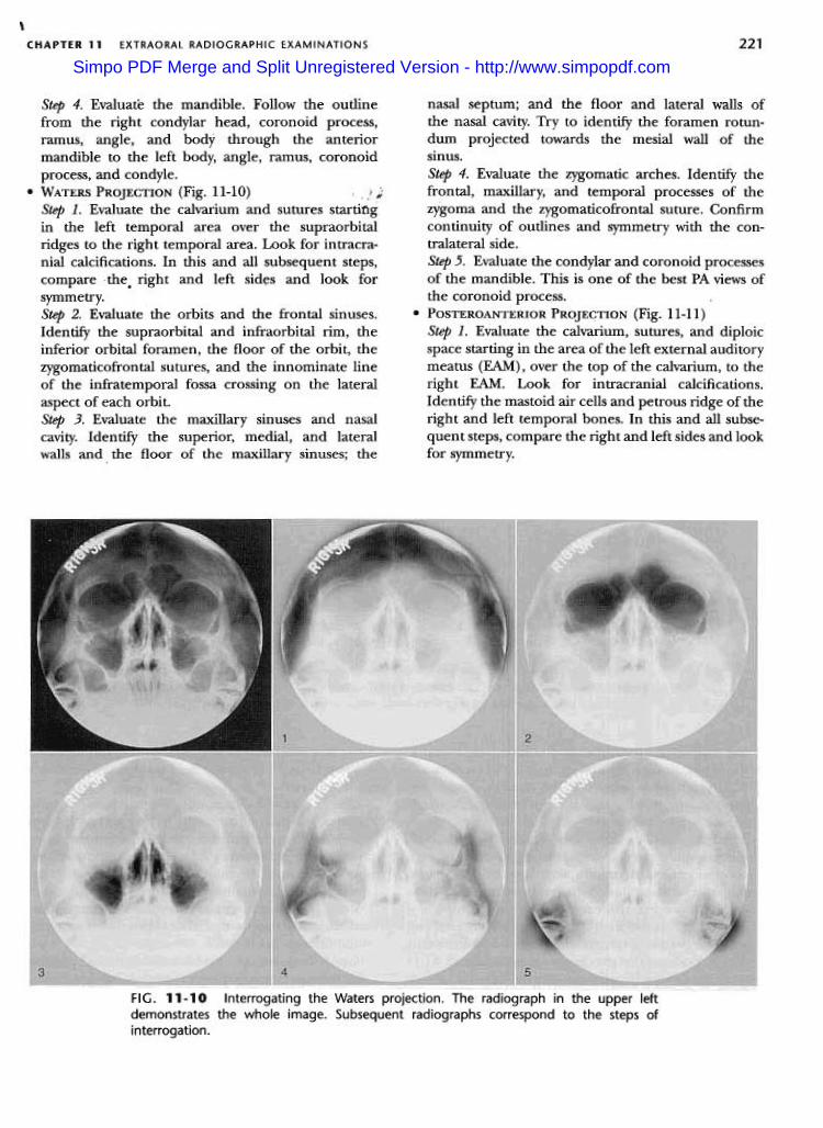
nasal septum; and the floor and lateral walls ofthe nasal cavity. Try to identify the foramen rotun-dum projected towards the mesial wall of thesinus.Step 4. Evaluate the zygomatic arches. Identify thefrontal, maxillary, and temporal processes of thezygoma and the zygomaticofrontal suture. Confirmcontinuity of outlines and symmetry with the con-tralateral side.Step 5. Evaluate the condylar and coronoid processesof the mandible. This is one of the best PA views ofthe coronoid process.
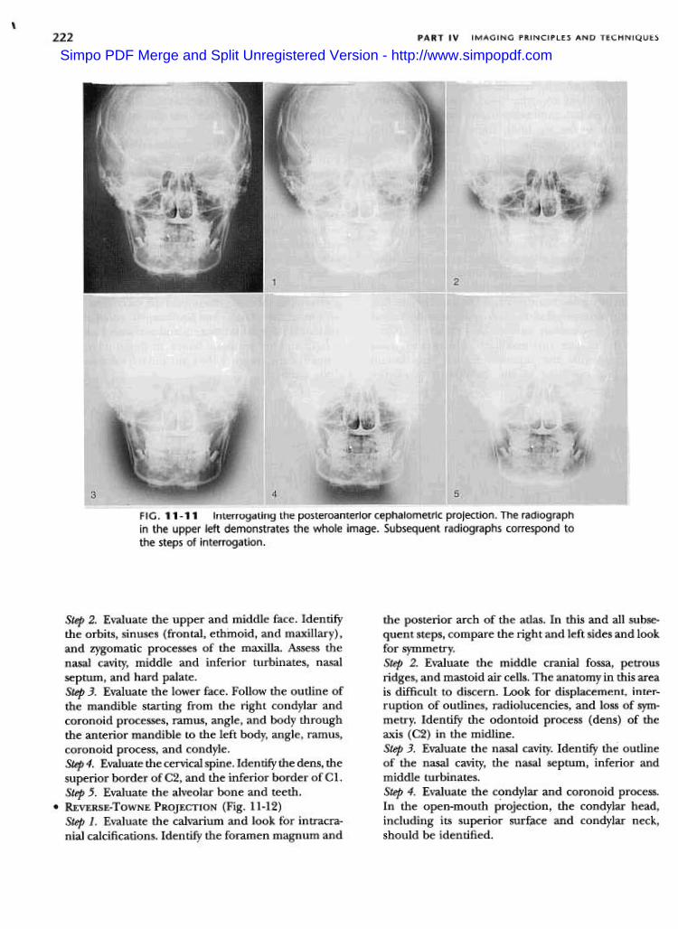
.POSTEROANTERIOR PROJECTION (Fig. 11-11)Step 1. Evaluate the calvarium, sutures, and diploicspace starting in the area of the left external auditorymeatus (EAM), over the top of the calvarium, to theright EAM. Look for intracranial calcifications.Identify the mastoid air cells and petrous ridge of theright and left temporal bones. In this and all subse-quent steps, compare the right and left sides and lookfor symmetry.
Step 4. Evaluate the mandible. Follow the outlinefrom the right condylar head, coronoid process,ramus, angle, and body through the anteriormandible to the left body, angle, ramus, coronoidprocess, and condyle.
.WATERS PROJECTION (Fig. 11-10) , fiStep 1. Evaluate the calvarium and sutures startingin the left temporal area over the supraorbitalridges to the right temporal area. Look for intracra-nial calcifications. In this and all subsequent steps,compare the. right and left sid~s and look for
symmetry.Step 2. Evaluate the orbits and the frontal sinuses.Identify the supraorbital and infraorbital rim, theinferior orbital foramen, the floor of the orbit, thezygomaticofrontal sutures, and the innominate lineof the infratemporal fossa crossing on the lateralaspect of each orbit.Step 3. Evaluate the maxillary sinuses and nasalcavity. Identify the superior, medial, and lateralwalls and. the floor of the maxillary sinuses; the
FIG. 11-10 Interrogating the Waters projection. The radiograph in the upper leftdemonstrates the whole image. Subsequent radiographs correspond to the steps of
interrogation.
Simpo PDF Merge and Split Unregistered Version - http://www.simpopdf.com
,222 PART IV IMAGING PRINCIPLES AND TECHNIQUES
FIG. 11-11 Interrogating the posteroanterior cephalometric projection. The radiographin the upper left demonstrates the whole image. Subsequent radiographs correspond tothe steps of interrogation.
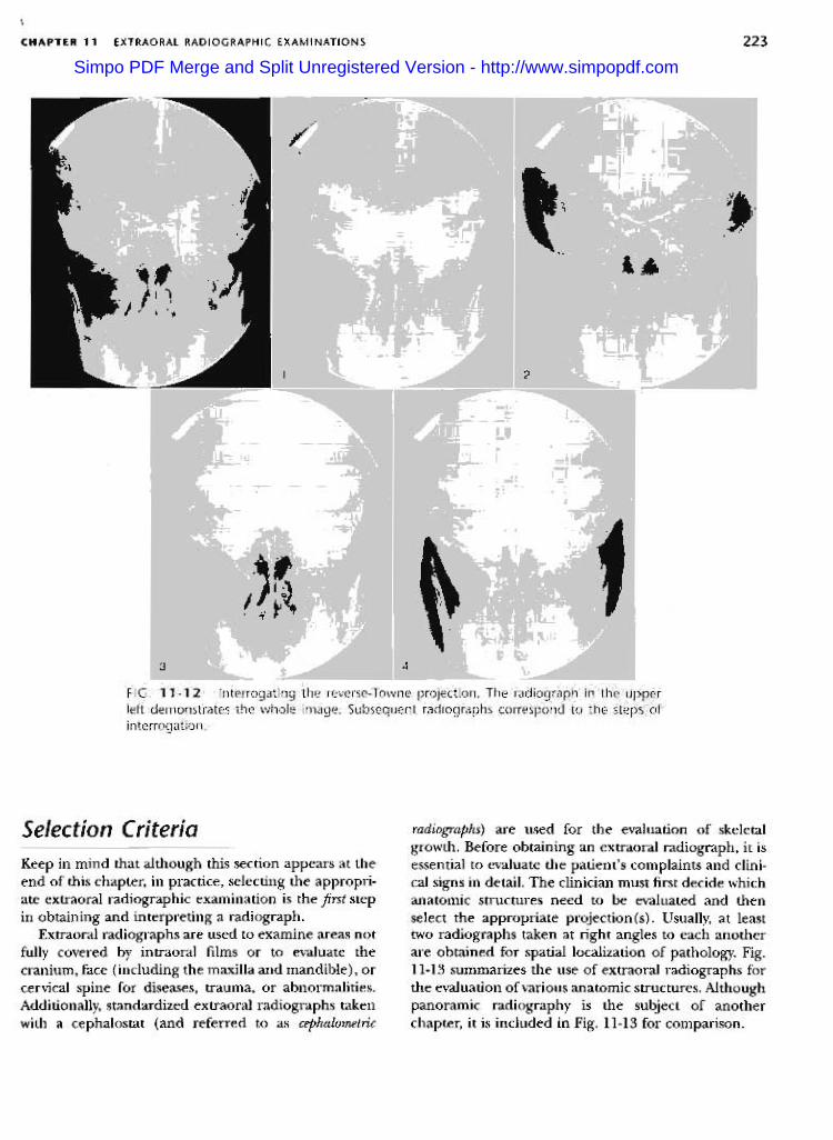
the posterior arch of the atlas. In this and all subse-quent steps, compare the right and left sides and lookfor symmetry.Step 2. Evaluate the middle cranial fossa, petrousridges, and mastoid air cells. The anatomy in this areais difficult to discern. Look for displacement, inter-ruption of outlines, radiolucencies, and loss of sym-metry. Identify the odontoid process (dens) of theaxis (C2) in the midline.Step 3. Evaluate the nasal cavity. Identify the outlineof the nasal cavity, the nasal septum, inferior andmiddle turbinates.Step 4. Evaluate the condylar and coronoid process.In the open-mouth projection, the condylar head,including its superior surface and condylar neck,should be identified.
Step 2. Evaluate the upper and middle face. Identifythe orbits, sinuses (frontal, ethmoid, and maxillary),and zygomatic processes of the maxilla. Assess thenasal cavity, middle and inferior turbinates, nasalseptum, and hard palate.Step 3. Evaluate the lower face. Follow the outline ofthe mandible starting from the right condylar andcoronoid processes, ramus, angle, and body throughthe anterior mandible to the left body, angle, ramus,coronoid process, and condyle.Step 4. Evaluate the cervical spine. Identify the dens, thesuperior border ofC2, and the inferior border ofC1.Step 5. Evaluate the alveolar bone and teeth.
.REVERSE-ToWNE PROJECTION (Fig. 11-12)Step 1. Evaluate the calvarium and look for intracra-nial calcifications. Identify the foramen magnum and
Simpo PDF Merge and Split Unregistered Version - http://www.simpopdf.com
223EXTRAORAL RADIOGRAPHIC EXAMINATIONS
\
CHAPTER 11
Selection Criteria radiographs) are used for the evaluation of skeletalgrowth. Before obtaining an extraoral radiograph, it isessential to evaluate the patient's complaints and clini-cal signs in detail. The clinician must first decide whichanatomic structures need to be evaluated and thenselect the appropriate projection(s). Usually, at leasttwo radiographs taken at right angles to each anotherare obtained for spatial localization of pathology. Fig.11-13 summarizes the use of extraoral radiographs forthe evaluation of various anatomic structures. Althoughpanoramic radiography is the subject of anotherchapter, it is included in Fig. 11-13 for comparison.
Keep in mind that although this section appears at theend of this chapter, in practice, selecting the appropri-ate extraoral radiographic examination is the first stepin obtaining and interpreting a radiograph.
Extraoral radiographs are used to examine areas notfully covered by intraoral films or to evaluate thecranium, face (including the maxilla and mandible) , orcervical spine for diseases, trauma, or abnormalities.Additionally, standardized extraoral radiographs takenwith a cephalostat (and referred to as cephalometric
Simpo PDF Merge and Split Unregistered Version - http://www.simpopdf.com

224 PART IV IMAGING PRINCIPLES AND TECHNIQUES
LateralCeph
PACeph
Reverse ObliqueTowne Body
LateralRamusSMV Waters Panoramic
Anterior mandible
Mandibular body
Ramus
Coronoid process
Condylar neck
Condylar head
Anterior maxilla
Posterior maxilla
Orbit
Zygoma
Zygomatic arch
Nasal bones
Nasal cavity
Maxillary sinus
Frontal sinus
Ethmoid sinus
Sphenoid sinus
.00
0.. 0 Low usefulness
.Medium usefulness
.High usefulnessNo symbol: Not recommened
000
.
0.0:.0
.-I..
0..f-(/)UJII:UJf-Z
u.0~UJII:~
.
D..D
0.Q
0.
..
D
0
D 0
0.
0FIG. 11-13 Relative usefulness of extraoral radiographic projections to display variousanatomic structures.
BIBLIOGRAPHY
Ballinger PW, Frank ED: Merrill's atlas of radiographic posi-tions and radiologic procedures, vol 2, ed 10, St. Louis,2003, Mosby, pp. 353-399.
Kantor ML, Norton LA: Normal radiographic anatomy andcommon anomalies seen in cephalometric films, Am JOrthod Dentofac Orthop 91:414-26, 1987.
Keats TE, Anderson MW: Atlas of normal roentgen variantsthat may simulate disease, ed 7, St. Louis, 2001, Mosby,pp. 3-275.
Shapiro R: Radiology of the normal skull, Chicago, 1981, YearBook Medical.
Swischuk LE: Imaging of the cervical spine in children, NewYork, 2002, Springer-Verlag.
Simpo PDF Merge and Split Unregistered Version - http://www.simpopdf.com