simply innovative integration -...
TRANSCRIPT
Simply innovativeintegration
LED Modules
Design-in Guide
Fortimo LLS EaseSelect
2 Philips Lighting
ContentsIntroduction to this guide 3 Information or support 3 Application note 3 Warnings and instructions 4 Cautions during storage and transportation 5Electrical design-in 6Mechanical design-in 8 System assembly instruction 8 Assembly in a fixture 12 Wires and connectors 15Optical design-in 16 Light distribution 16 Ray sets 16 Color consistency (SDCM) 17 Spectral light distribution 17 Reflector design 18Thermal design-in 18Reliability 19 Impact of thermal cycling on product failure 19 Lumen maintenance of the Fortimo LED linear modules B50L70 @ 50,000 hours 20 LM-80 data and DLC compliance 20 Lumen maintenance for different Tc temperatures 2 1
Quality, compliance and approval 22 Chemical compatibility 22 Compliance and approval marks 23 Ingress protection – IP rating, humidity and condensation 23 Blue light hazard 24 System disposal 25 Relevant standards 25 Safety 25 Electromagnetic compatibility 25 Environmental 25Contact details and suggested suppliers 26 Philips Fortimo LED linear systems 26 Philips PInS ESD support 26 ESD-related material and tool suppliers 26Disclaimer 27

3
Introduction to this guide
This guide contains information to help you design Philips Fortimo LLS EaseSelect low voltage (LV) product into a luminaire. We advise you to consult our website for the latest up-to-date information.
Information or support
If you require any further information or support, please consult your local Philips sales
representative or visit www.philips.com/oemna.
Application note
The Fortimo linear lighting system (LLS) EaseSelect (ES) is Philips’ first linear integrated
LED light engine solution that combines a UL Class 2 constant current LED driver and a
L2 LED module into a fully optimized system.
It enables OEM fixture manufacturers to design and manufacture LED fixtures meeting
minimum performance requirements optimized for most economic fixture designs.
Its patented system design provides opportunity to optimize the mechanical and electrical
fixture bill of materials while delivering high quality of light and performance.
With the application of commercial LED strip and waterproof fixtures in mind, Philips has
designed this economic system solution to provide added value to designers.
Long-lasting and low-maintenance, LED-based light sources are an excellent solution
for indoor environments. For optimal performance, these lighting applications require
a reliable power source matching the long lifetime of the LEDs. The perfectly married
component choices of LED driver and LED module offer reliability and flexibility for
optimal solutions in luminaire design.
Terms and definitions
In this guide, there will be references to three terms when referring to the Fortimo LLS
EaseSelect product.
LED module: L2 linear light engine that is comprised of PCB material, LEDs and
other electrical components, such as connectors
LED driver: LED Class 2 power source that transforms line voltage into DC voltage
to power LED module
LED system: This defines the system of LED module and LED driver as an
assembled system
Fortimo LLS ES
Design-in Guide
Introduction
to This Guide
4 Philips Lighting
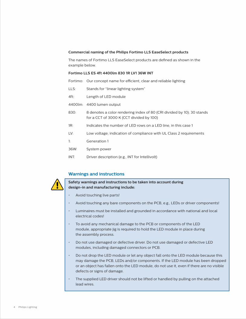
Commercial naming of the Philips Fortimo LLS EaseSelect products
The names of Fortimo LLS EaseSelect products are defined as shown in the
example below.
Fortimo LLS ES 4ft 4400lm 830 1R LV1 36W INT
Fortimo: Our concept name for efficient, clear and reliable lighting
LLS: Stands for “linear lighting system”
4ft: Length of LED module
4400lm: 4400 lumen output
830: 8 denotes a color rendering index of 80 (CRI divided by 10); 30 stands
for a CCT of 3000 K (CCT divided by 100)
1R: Indicates the number of LED rows on a LED line, in this case 1
LV: Low voltage; indication of compliance with UL Class 2 requirements
1: Generation 1
36W: System power
INT: Driver description (e.g., INT for Intellivolt)
Warnings and instructions
Safety warnings and instructions to be taken into account during design-in and manufacturing include:
• Avoid touching live parts!
• Avoid touching any bare components on the PCB, e.g., LEDs or driver components!
• Luminaires must be installed and grounded in accordance with national and local
electrical codes!
• To avoid any mechanical damage to the PCB or components of the LED
module, appropriate jig is required to hold the LED module in place during
the assembly process.
• Do not use damaged or defective driver. Do not use damaged or defective LED
modules, including damaged connectors or PCB.
• Do not drop the LED module or let any object fall onto the LED module because this
may damage the PCB, LEDs and/or components. If the LED module has been dropped
or an object has fallen onto the LED module, do not use it, even if there are no visible
defects or signs of damage.
• The supplied LED driver should not be lifted or handled by pulling on the attached
lead wires.

5
Fortimo LLS ES
Design-in Guide
Introduction
to This Guide
• The luminaire manufacturer is responsible for its own luminaire design and must
comply with all relevant safety and performance standards. The general UL 1598
recommendations for luminaire design and legal safety are also applicable to
Philips Fortimo LLS EaseSelect.
• Cap off all unused wires to prevent accidental contact with live terminals.
• Do take into account the minimum required creepage and clearance distances.
• Do not apply mains power to the LED module directly.
• Connect all electrical components first before switching on mains.
• Do not service the luminaire when the mains voltage is connected; this includes
connecting or disconnecting the LED module’s cables.
• This LED driver is not suited for DC input operation!
• The Philips Fortimo LLS EaseSelect is intended for built-in use and should not
be exposed to the elements, such as snow, water or ice. It is the luminaire
manufacturer’s responsibility to prevent exposure. Fortimo LLS EaseSelect
products are specified for UL damp and dry locations.
• For optimal reliability of the LED module, we advise not to apply an AC electric
strength test to the luminaire, as this might damage the LEDs. It is recommended
instead to apply an insulation resistance measurement at 500 VDC.
• For support with any of these aspects, please contact your local Philips
sales representative.
Cautions during storage and transportation
When storing this product for a long time (more than one week)
• Store in a dark place. Do not expose to direct sunlight.
• For Philips LED linear modules, do maintain temperature and relative
humidity between specified range as stated in the respective datasheets
(www.philips.com/oemna).
6 Philips Lighting
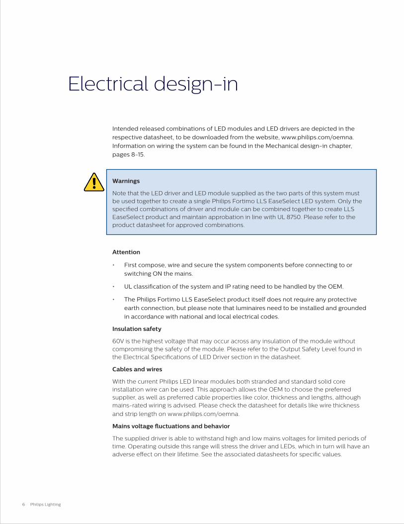
Intended released combinations of LED modules and LED drivers are depicted in the
respective datasheet, to be downloaded from the website, www.philips.com/oemna.
Information on wiring the system can be found in the Mechanical design-in chapter,
pages 8-15.
Warnings
Note that the LED driver and LED module supplied as the two parts of this system must be used together to create a single Philips Fortimo LLS EaseSelect LED system. Only the specified combinations of driver and module can be combined together to create LLS EaseSelect product and maintain approbation in line with UL 8750. Please refer to the product datasheet for approved combinations.
Attention
• First compose, wire and secure the system components before connecting to or
switching ON the mains.
• UL classification of the system and IP rating need to be handled by the OEM.
• The Philips Fortimo LLS EaseSelect product itself does not require any protective
earth connection, but please note that luminaires need to be installed and grounded
in accordance with national and local electrical codes.
Insulation safety
60V is the highest voltage that may occur across any insulation of the module without compromising the safety of the module. Please refer to the Output Safety Level found in the Electrical Specifications of LED Driver section in the datasheet.
Cables and wires
With the current Philips LED linear modules both stranded and standard solid core installation wire can be used. This approach allows the OEM to choose the preferred supplier, as well as preferred cable properties like color, thickness and lengths, although mains-rated wiring is advised. Please check the datasheet for details like wire thickness
and strip length on www.philips.com/oemna.
Mains voltage fluctuations and behavior
The supplied driver is able to withstand high and low mains voltages for limited periods of time. Operating outside this range will stress the driver and LEDs, which in turn will have an adverse effect on their lifetime. See the associated datasheets for specific values.
Electrical design-in
7
Fortimo LLS ES
Design-in Guide
Electrical
Design-in
Leakage current
Philips Fortimo LLS EaseSelect products are designed to meet leakage current
requirements per UL 8750 standards. In a luminaire, leakage current may be higher since
the LED load introduces additional parasitic capacitance. As such, precautions should be
taken at the luminaire level and also if multiple products are used in the luminaire.
Surge protection
Note: Please consult the fuse and circuit breaker manufacturer recommendations when
selecting appropriate fuse and/or circuit breakers in conjunction with LED luminaires.
Philips Fortimo LLS EaseSelect products have limited built-in surge protection (in
accordance with IEEE /ANSIC82.77-5 Transient Surge Requirements). Additional protection
against excessive high surges can be achieved by adding a surge protection device.
The actual limit can differ per product and can be found in the product’s datasheet on
www.philips.com/oemna.
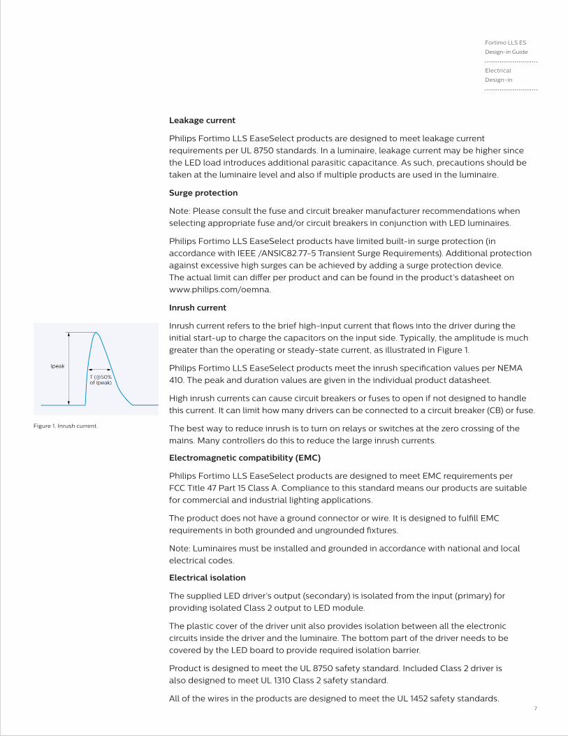
Inrush current
Inrush current refers to the brief high-input current that flows into the driver during the
initial start-up to charge the capacitors on the input side. Typically, the amplitude is much
greater than the operating or steady-state current, as illustrated in Figure 1.
Philips Fortimo LLS EaseSelect products meet the inrush specification values per NEMA
410. The peak and duration values are given in the individual product datasheet.
High inrush currents can cause circuit breakers or fuses to open if not designed to handle
this current. It can limit how many drivers can be connected to a circuit breaker (CB) or fuse.
The best way to reduce inrush is to turn on relays or switches at the zero crossing of the
mains. Many controllers do this to reduce the large inrush currents.
Electromagnetic compatibility (EMC)
Philips Fortimo LLS EaseSelect products are designed to meet EMC requirements per
FCC Title 47 Part 15 Class A. Compliance to this standard means our products are suitable
for commercial and industrial lighting applications.
The product does not have a ground connector or wire. It is designed to fulfill EMC
requirements in both grounded and ungrounded fixtures.
Note: Luminaires must be installed and grounded in accordance with national and local
electrical codes.
Electrical isolation
The supplied LED driver’s output (secondary) is isolated from the input (primary) for
providing isolated Class 2 output to LED module.
The plastic cover of the driver unit also provides isolation between all the electronic
circuits inside the driver and the luminaire. The bottom part of the driver needs to be
covered by the LED board to provide required isolation barrier.
Product is designed to meet the UL 8750 safety standard. Included Class 2 driver is
also designed to meet UL 1310 Class 2 safety standard.
All of the wires in the products are designed to meet the UL 1452 safety standards.
Figure 1. Inrush current.

8 Philips Lighting
Mechanical design-in
The Fortimo LLS EaseSelect is a system that needs to be composed of a LED module (Fortimo LLS ES) and a compatible LED driver.
System assembly instruction
Caution:
Do not handle the LED driver by the output wires or pull on the wires! Doing so will
damage the connector and electrical connection.
Do not touch the LEDs!
The module shall be handled in a way that maintains flatness and prevents excessive
flexing during the assembly process. To avoid any mechanical damage to the PCB or
components of the LED module, an appropriate jig is required to hold the LED module
in place during the assembly process.
The driver is mechanically secured to the backside of the LED module (the side where
no LEDs are located). There can be multiple mounting positions for the driver. Please
refer to the product datasheet for exact mounting positions.
Figure 2. System assembly.

9
Fortimo LLS ES
Design-in Guide
Mechanical
Design-in
Mechanical design-in The pictures below show an example of assembly for the Fortimo LLS EaseSelect 4ft
4400lm LV1 36W INT.
The mechanical and electrical connection between LED driver and LED module can be
made in a few simple steps that are described next. Depending on the fixture design, the
driver can be located either on position 1 or position 2.
Step 1: Positioning of the LED driver on the LED module
Hook-in the outer pins of the driver in the LED module.
Figure 3. Position 1.
Figure 5. LED driver assembly position 1. Figure 6. LED driver assembly position 2.
Figure 4. Position 2.
10 Philips Lighting
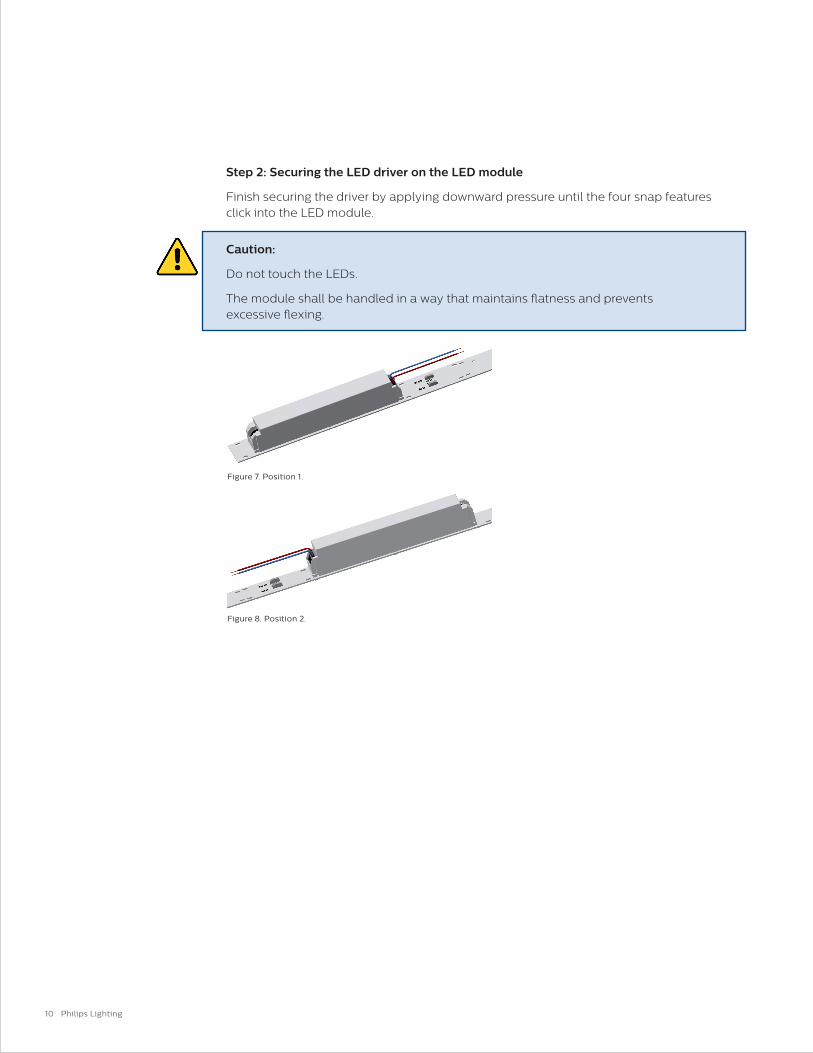
Step 2: Securing the LED driver on the LED module
Finish securing the driver by applying downward pressure until the four snap features click into the LED module.
Caution:
Do not touch the LEDs.
The module shall be handled in a way that maintains flatness and prevents excessive flexing.
Figure 8. Position 2.
Figure 7. Position 1.

11
Step 3: Creating the electrical connection between LED module and LED driver
Both the LED module and LED driver are equipped with push-in connectors. No specific cabling other than standard installation wire is required. To find details of each connector, see the respective datasheet of the product you use.
Note: The LED modules are polarity-sensitive. The wiring schematic can be found toward the end of the product datasheet. Datasheets can be downloaded from www.philips.com/oemna.
Please make sure the RED (+) and BLUE (-) wires are connected to the connectors that are marked accordingly. For position 2 the output wires of the LED driver should cross each other for making the correct connection.
Fortimo LLS ES
Design-in Guide
Mechanical
Design-in
Figure 9. Electrical connection LED module and LED
driver position 1.
Table 1. LED driver output wires.
Figure 10. Electrical connection LED module and LED
driver position 2.
Wire Color Value
Blue LED output minus (-)
Red LED output plus (+)

12 Philips Lighting
Step 4: Creating the mains voltage connection of the LED driver
Connect external mains wires to the connector (Black = Line, White = Neutral). The
LED driver does not require a functional or safety earth connection. The fixture design
determines if safety earth for the fixture’s metal parts is needed (responsibility of
OEM customer).
The mains supply has to be connected to the mains connector on the driver, not the
connector on the LED board. The mains wire installation should be done in accordance
with the national and local electrical codes. Please refer to the datasheet for strip length
and wire diameters.
Assembly in a fixture
The LED module can be mounted in a fixture where the PCB of the LED module can act as
(part) of the UL electrical and fire enclosure. Please refer to UL conditions of acceptability
(CoA) for additional details.
Securing and mounting methods
With the Philips Fortimo LLS EaseSelect LED system, securing methods other than screws
can be explored. In order to achieve this, larger copper-free isles have been designed on
both edges of the LED module. Care should be taken to ensure clamping pressure on the
PCB still maintains flatness of the LED linear module. Alternate style fasteners or mounting
may be used as long as it is properly secured, flatness is achieved and creepage and
clearances are maintained.
Fixture manufacturer must follow UL 1598 to maintain proper clearances.
Table 2. Mains wires.
Mains Connector Value
White Neutral (mains input)
Black Line (mains input)
Figure 11. Connect mains wires.
13
Fortimo LLS ES
Design-in Guide
Mechanical
Design-in
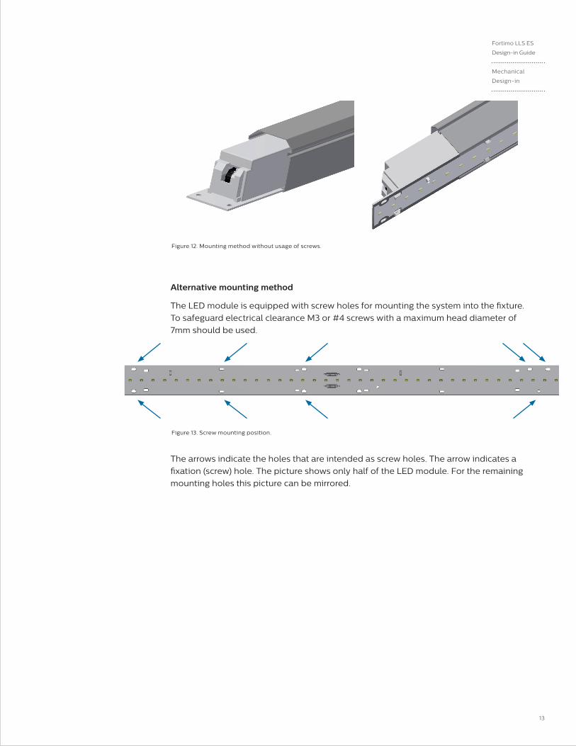
Alternative mounting method
The LED module is equipped with screw holes for mounting the system into the fixture.
To safeguard electrical clearance M3 or #4 screws with a maximum head diameter of
7mm should be used.
The arrows indicate the holes that are intended as screw holes. The arrow indicates a
fixation (screw) hole. The picture shows only half of the LED module. For the remaining
mounting holes this picture can be mirrored.
Figure 13. Screw mounting position.
Figure 12. Mounting method without usage of screws.
14 Philips Lighting
Securing the module
Optionally, you can omit some mounting points as long as the module is properly
secured and flatness is maintained. No additional heat sinking is required. However, this
must be verified by measuring the Tc temperature of the driver and module.
Screws, washers and mounting holes
To ensure the electrical insulation when using, for example, M3 or #4 metal screws, the
diameter of the screw head (and optional metal washer) must not exceed 7mm in order
to maintain proper clearance to avoid functional damage to the LED module. When using
electrically non-conductive materials the size could be allowed larger than that.
Damage of insulation layer
In general, the surface of the PCB must not be damaged by mounting materials, as this
may compromise the electrical insulating layer. However, scratching of the PCB’s white top
layer in the region that is intended for fixation by screw will not lead to loss of function or
reliability. The area around fixation holes does not carry any copper tracks. This can be seen
when looking carefully at the LED module. The mounting materials must still comply with
the relevant creepage and clearance.
Screw torque
The maximum torque that should be applied depends on the screw type and luminaire
material. The fasteners used to secure the LED module to a heat sink must be tightened
with a torque in accordance with the table below for an M3 or #4 screw.
Note: When tightening the fasteners it is best to start the fasteners into the module to allow
the module to be centered and then tighten the fasteners from the center of the module to
the ends of the module. This will help to ensure that the module will lie flat on the mounting
surface and minimize any gaps that may occur.
Warning
If a luminaire requires protective earth, all conductive parts – like the reflector – must
be electrically connected to protective earth in order to prevent hazardous conditions.
Required minimum clearance distance
Depending the maximum driver output voltages that can occur under normal
working conditions, UL 840 prescribes minimum clearance distances.
Table 3. Maximum screw torque.
Fixture Material Screw Torque for M3 or #4 Screw Max
Steel, thread forming screws 0.8 Nm

15
Fortimo LLS ES
Design-in Guide
Mechanical
Design-in
Wires and connectors
Removal of RED (+) and BLUE (-) wires from connector can be released without tools
by simultaneously twisting and pulling the wire.
Removal of the mains wires can be released from the connector by pushing the
release button.
All wires must be fully inserted such that the wire insulation is inserted into and
surrounded by the end of the housing (no bare wire should be visible).
Complementary partners for fixation alternatives
Fixation materials, such as screws, are not part of the Philips Fortimo LLS EaseSelect
LED system offering. This is an added-value area for OEMs, offering the possibility to
differentiate. However, there are several suppliers offering push-and-fix-like components
or adhesive tapes, enabling quick and easy luminaire creation. Some of these are listed
in the complementary partner section in our OEM LED components catalog (available in
printed and digital formats) or in the support section on www.philips.com/oemna.
Reference to these products does not necessarily mean they are endorsed by Philips.
Philips gives no warranties regarding these products and assumes no legal liability or
responsibility for any loss or damage resulting from the use of the information given here.
We advise not to use bare plastic push-pin fasteners (without any metal parts), as these are
likely to wear out before the lifetime of the LED product is reached, reducing the mechanical
and thermal contact between the LED module and the luminaire.

16 Philips Lighting
Optical design-in
Optics on top of or near the LED linear modules
Luminaire manufacturers have the freedom to design their own optics in order to maximize the lm/W efficiency and beam shape of the system.
Secondary optics is not part of the Philips Fortimo LLS EaseSelect LED system offering. This is an added-value area for OEMs, offering the possibility to differentiate. However, there are many companies offering, for example, reflectors, lenses or bulk diffusers and that have a standard portfolio of compatible optics available, enabling quick and easy luminaire creation. Some of these are listed in the complementary partner section in our LED components catalog (available in print and digital formats) or in the support section on www.usa.lighting.philips.com/products/oem-components/fortimo-led-modules. Reference to these products does not necessarily mean they are endorsed by Philips. Philips gives no warranties regarding these products and assumes no legal liability or responsibility for any loss or damage resulting from the use of the information given here.
Light distribution
Philips LED linear modules generate a Lambertian beam shape (see light distribution
diagram). The IES (or .ldt) files are available via the website
www.usa.lighting.philips.com/products/oem-components/fortimo-led-modules.
Ray sets
Ray set files are available for customer use and can be downloaded on
www.usa.lighting.philips.com/products/oem-components/fortimo-led-modules.
All ray set files are available containing 100,000, 500,000 and 5,000,000 rays,
although due to their size the last two types are not on the website. Please contact
your Philips representative to obtain these separately if required.
The origin of the ray sets is shown in the accompanying slide deck presentation file per
module type, as are the 3D step files, on the website.
Software File extension
ASAP .dis
Light Tools (ASCII) .ray
TracePro/Oslo (ASCII) .dat
Zemax .dat
Explanation & definitions .ppt
Solid 3D model .stp
Figure 14. Light distribution.
Table 4. Ray set zip file contains typically.
17
Fortimo LLS ES
Design-in Guide
Optical Design-in
Color consistency (SDCM)
Color consistency refers to the spread in color points between modules. It is specified in SDCM
(Standard Deviation of Color Matching) or MacAdam ellipses, which are identical. The value
refers to the size of an ellipse around a point close to the black body locus. Staying within this
ellipse results in a consistency of light, which ensures that no color difference is perceivable
between one LED module and another with the naked eye in most applications.
SDCM value in the datasheet represents an integrated measurement over the complete
LED module.
Please be aware that in applications that are more sensitive for color differences (color
consistency of <3 SDCM), such as wall washers (<2 SDCM), we advise you to contact your
local Philips representative or the Philips design-in team for expertise and support in
luminaire design and evaluation.
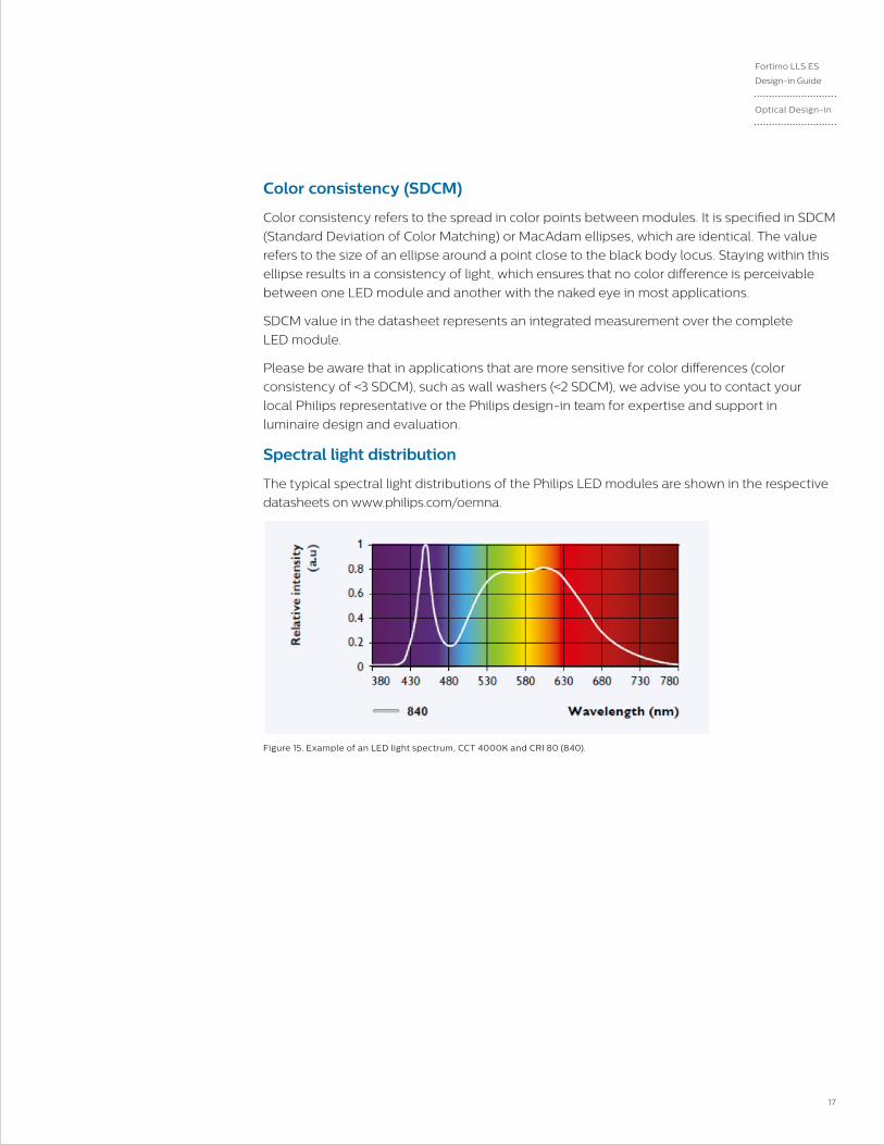
Spectral light distribution
The typical spectral light distributions of the Philips LED modules are shown in the respective
datasheets on www.philips.com/oemna.
Figure 15. Example of an LED light spectrum, CCT 4000K and CRI 80 (840).

18 Philips Lighting
Reflector design
If a reflector is designed around the LED module, it is essential to allow a proper clearance
distance between the LED module and reflector around the LED module surface, LEDs,
electrical components and the connectors. This clearance distance is necessary to ensure
safe insulation of the system and is in line with UL 1598 to prevent short circuiting, damage
and an open circuit to the LED module.
Figure 16. Fortimo LLS ES system.
Figure 17. Reference luminaire.
Thermal design-in
Depending on the thermal capability of the fixture, no additional heat sinking may be
required. However, this must be verified by measuring the Tc temperature of the driver
and module. Please refer to the datasheet for the exact location of these Tc points.
An example reference fixture is shown in Figure 18. In this fixture without additional heat
sinking, Tclife was met up to an ambient temperature of 35°C.
Fixtures can be designed for higher ambient temperature by additional heat sinking
methods. Please refer to the linear module design-in guide document (PLt-1590DG)
available on the components website, www.philips.com/oemna.

19
Fortimo LLS ES
Design-in Guide
Reliability
Thermal design-in
Impact of thermal cycling on product failure
Not only the drive current (mA) and steady state case temperature (Tc °C) have an impact
on the lifetime of LEDs. Also the number of full thermal cycles has a significant impact on
product failure. A full thermal product cycle means the complete warm up to stabilized Tc
of the product in use and full cool down to ambient temperature (Tamb) of the product
being switched off. For your convenience the amount of warranted full thermal product
cycles of the LED product at a given Tc is stated in the datasheet, which can be found on
www.philips.com/ledmodulesna. Electrically faster switching, thereby not reaching the
thermal limits of a full thermal cycle, will allow for higher numbers.
Note:
Always take the Tc temperature limits into account as stated in the datasheet for the LED
module you use.
Warranted number of full thermal product cycles at which the survival rate of the population ≥90%, at 25°C ambient temperature
Case Temperature Tc [°C] LED Module 1 LED Module 2
35 14,600
40
45 14,000
50
55 12,000 14,600
60
65 8,000 14,600
70
75 6,000 14,000
80 6,000
85 10,000
90 8,000
Table 5. Example: Warranted number of full thermal cycles at 25C degree ambient.
Example:
LED module 1 with Tc 65°C at Tamb 25°C has a warranted number of full thermal product
cycles of 8,000.
Example:
LED module 2 with Tc 65°C at Tamb 25°C has a warranted number of full thermal product
cycles of 14,600.
Reliability

20 Philips Lighting
Lumen maintenance B50L70 @ 50,000 hours
The quality of the LED linear portfolio is underpinned with Philips’ claim of B50L70 at
50,000 hours. This means that at 50,000 hours of operation at least 50% of the LED
population will emit at least 70% of its original amount of lumens. The decreased lumen
level can be a result of less light out of an LED, discrete LEDs failing – leading to
a reduced lumen output of the luminaire – or a combination of the two. This is contrary
to conventional light sources, where sometime after service life hours the conventional light
source emits no light at all. In this section the example graphs show the estimated lumen
depreciation curves for different percentage of the population and for different
Tc temperatures. The actual data for the LED linear modules can be found in the
associated datasheet.
Please refer to the associated LED module datasheet for the specific lumen
maintenance graphs.
LM-80 data and DLC compliance
The DesignLights Consortium® (DLC) promotes quality, performance and energy-efficient
commercial sector lighting solutions through collaboration among its federal, regional,
state, utility and energy efficiency program members, luminaire manufacturers, lighting
designers and other industry stakeholders throughout the U.S. and Canada. Since 2010,
the DLC has administered the Commercial LED Luminaire Qualified Products List (QPL), a
leading resource that identifies quality, energy-efficient LED luminaires for the commercial
sector. The DLC follows the ENERGY STAR guidance for lumen maintenance testing that
includes IES LM-80 test procedures and the application of LM-80 data using the IES TM-21
procedure to determine the long-term lumen maintenance of an LED light source. IES
TM-21 applies an exponential least squares curve-fit through the average values provided
in the LM-80 data. The TM-21 calculator that is used to determine the estimated long-term
lumen maintenance can be found at the Department of Energy website. The LM-80 data
for the LEDs used for each Philips LED module is available on request from your sales
representative. Please contact them for assistance in obtaining this information.
Note: TM21 refers to Tc sometime as the solder temperature of the LED measured in the insitu-test. This Tc is not equal to the Tc point of the Philips Fortimo LED modules that are used for thermal design-in. However, there is a clear thermal correlation between Ts and Tc designed for within any Fortimo LED module. The exact temperature difference (dT) depends on fixture design and application conditions.
Warning
Lumen maintenance of the LED device is not a proxy for luminaire lifetime as
it does not account for other potential failure modes in the luminaire, such as
driver failure, failure of connections, failure of optical systems, etc. Therefore,
it is strongly suggested to not use TM21 predictions and calculations as the
sole data point to specify luminaire lifetime.
21
Fortimo LLS ES
Design-in Guide
Reliability
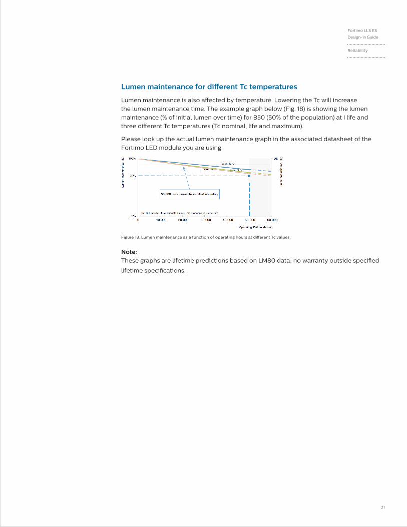
Lumen maintenance for different Tc temperatures
Lumen maintenance is also affected by temperature. Lowering the Tc will increase
the lumen maintenance time. The example graph below (Fig. 18) is showing the lumen
maintenance (% of initial lumen over time) for B50 (50% of the population) at I life and
three different Tc temperatures (Tc nominal, life and maximum).
Please look up the actual lumen maintenance graph in the associated datasheet of the
Fortimo LED module you are using.
Figure 18. Lumen maintenance as a function of operating hours at different Tc values.
Note: These graphs are lifetime predictions based on LM80 data; no warranty outside specified
lifetime specifications.
22 Philips Lighting
Quality, complianceand approval
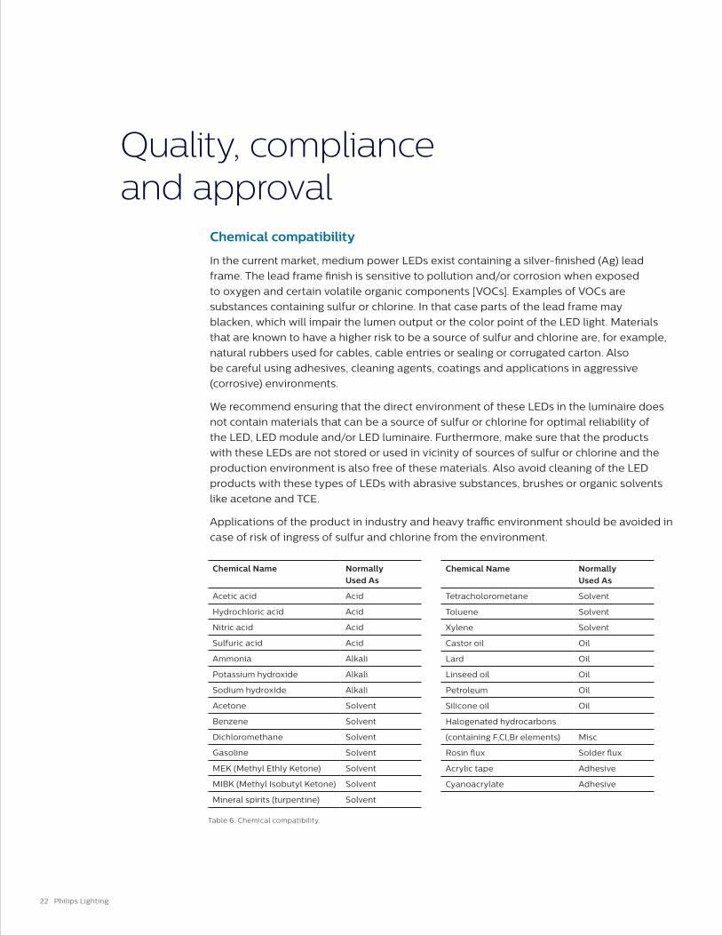
Chemical compatibility
In the current market, medium power LEDs exist containing a silver-finished (Ag) lead
frame. The lead frame finish is sensitive to pollution and/or corrosion when exposed
to oxygen and certain volatile organic components [VOCs]. Examples of VOCs are
substances containing sulfur or chlorine. In that case parts of the lead frame may
blacken, which will impair the lumen output or the color point of the LED light. Materials
that are known to have a higher risk to be a source of sulfur and chlorine are, for example,
natural rubbers used for cables, cable entries or sealing or corrugated carton. Also
be careful using adhesives, cleaning agents, coatings and applications in aggressive
(corrosive) environments.
We recommend ensuring that the direct environment of these LEDs in the luminaire does
not contain materials that can be a source of sulfur or chlorine for optimal reliability of
the LED, LED module and/or LED luminaire. Furthermore, make sure that the products
with these LEDs are not stored or used in vicinity of sources of sulfur or chlorine and the
production environment is also free of these materials. Also avoid cleaning of the LED
products with these types of LEDs with abrasive substances, brushes or organic solvents
like acetone and TCE.
Applications of the product in industry and heavy traffic environment should be avoided in
case of risk of ingress of sulfur and chlorine from the environment.
Chemical Name Normally Used As
Acetic acid Acid
Hydrochloric acid Acid
Nitric acid Acid
Sulfuric acid Acid
Ammonia Alkali
Potassium hydroxide Alkali
Sodium hydroxide Alkali
Acetone Solvent
Benzene Solvent
Dichloromethane Solvent
Gasoline Solvent
MEK (Methyl Ethly Ketone) Solvent
MIBK (Methyl Isobutyl Ketone) Solvent
Mineral spirits (turpentine) Solvent
Chemical Name Normally Used As
Tetracholorometane Solvent
Toluene Solvent
Xylene Solvent
Castor oil Oil
Lard Oil
Linseed oil Oil
Petroleum Oil
Silicone oil Oil
Halogenated hydrocarbons
(containing F,Cl,Br elements) Misc
Rosin flux Solder flux
Acrylic tape Adhesive
Cyanoacrylate Adhesive
Table 6. Chemical compatibility.

23
Fortimo LLS ES
Design-in Guide
Quality,
Compliance
and Approval
The Philips LED linear family makes use of LEDs with previously explained type of lead
frame. Therefore, the noted recommendations apply for the Fortimo LED linear modules.
Philips Fortimo LED linear systems comply with the standards shown in below paragraphs.
A list of chemicals, often found in electronics and construction materials for luminaires
that should be avoided, is provided in Table 13. Note that Philips does not warrant that
this list is exhaustive because it is impossible to determine all chemicals that may affect
LED performance. These chemicals may not be directly used in the final products, but
some of them may be used in intermediate manufacturing steps (e.g., cleaning agents).
Consequently, trace amounts of these chemicals may remain on (sub) components, such
as heat sinks. It is recommended to take precautions when designing your application.
In case of questions on compatibility of materials or applications of the product, please
contact your local Philips sales representative for application support.
Compliance and approval marks
The Fortimo LED linear family is UL/CSA approved. The relevant standards are summarized
at the end of this chapter. To ensure luminaire approval, the conditions of acceptance
need to be fulfilled. Details can be requested from your local sales representative. All
luminaire manufacturers are advised to conform to the international standards of luminaire
design (UL 1598).
Ingress protection – IP rating, humidity and condensation
Photobiological safety
The Fortimo LED Linear systems are build-in systems and, therefore, have no IP
classification. They are not designed for operation in the open air. The OEM is responsible
for proper IP classification and approbation of the luminaire. The Fortimo LED linear
modules have been developed and released for use in damp locations and not for
locations where condensation is present. If there is a possibility that condensation could
come into contact with the modules, the system/luminaire builder must take precautions to
prevent this.
The lamp standard IEC 62471 "Photobiological safety of lamps and lamp systems" gives
guidance on evaluating the photobiological safety of lamps and lamp systems, including
luminaires. It specifically defines the exposure limits, reference measurement technique
and classification scheme for the evaluation and control of photobiological hazards from
all electrically powered incoherent broadband sources of optical radiation, including
LEDs, in the wavelength range from 200 nm to 3000 nm. Measurement results for LED
products are given in Table 7. Based on these measurements, the conclusion is no safety
measures are required.

24 Philips Lighting
Blue light hazard
From the nature of most LEDs applying blue light, emphasis has been put on the hazard in
terms of Photo Biological Safety (PBS). Evaluation by the European lighting industry (ELC,
Celma) has concluded LED light sources are safe for customers when used as intended.
Nevertheless, luminaire makers have to comply with luminaire standards, including PBS.
To avoid extensive retesting, the market prefers to build on the test conclusions of the
LED (module) suppliers. The testing conclusion then will be expressed in Risk Groups
(RG), where RG0 and RG1 do not require marking and/or specific action for the OEM (as
compared to RG2 and 3). The certificates with the verdict of the LED products can be found
on www.philips.com/ledmodulesna.
Some facts on blue light.
• All light – visible, IR, UV – causes fading.
• It has long been known that blue light causes fading in yellow pigments.
• LEDs do not produce more blue light than other sources by its nature.
• Blue light content is relative to color temperature, not to light source.
“Often, investigations into the effect of short-wavelength radiation—be it on humans or
artwork—suggest that LEDs are dangerous because they emit more blue light than other
sources like incandescent bulbs or CFLs. While it is true that most LED products that emit
white light include a blue LED pump, the proportion of blue light in the spectrum is not
significantly higher for LEDs than it is for any other light source at the same correlated color
temperature (CCT).” (Department of Energy).
For more details follow the link for the U.S. Department of Energy: http://apps1.eere.energy.
gov/buildings/publications/pdfs/ssl/opticalsafety_fact-sheet.pdf.
Item Result: Risk Group
Actinic UV Exempt
Near-UV Exempt
Retinal Blue Light Exempt
Retinal Blue SmallScr Exempt
Retinal thermal Exempt
Infrared Eye Exempt
Table 7. Ingress protection – IP rating, humidity and condensation photobiological safety.
25
Fortimo LLS ES
Design-in Guide
Quality,
Compliance
and Approval
System disposal
We recommend that the Fortimo LED modules and its components are disposed of in an
appropriate way at the end of their (economic) lifetime. The modules are in effect normal
pieces of electronic equipment containing components that are currently not considered to
be harmful to the environment. We, therefore, recommend that these parts are disposed of
as normal electronic waste, in accordance with local regulations.
Relevant standards
Safety
UL8750/CSA 22.2 250-13 modules for general lighting
- safety specifications
IEC 62471 Photobiological safety of lamps and lamp systems
UL8750/SSL 7/CSA22.2 250-13 Lamp control gear
Electromagnetic compatibility
(Tested with LED linear modules, cables and Philips Advance Xitanium LED driver).
FCC47 subpart 15 Class A Limits and methods of measurement of radio disturbance
characteristics of electrical lighting and similar equipment.
FCC47 subpart 15 Class A Equipment for general lighting purposes – EMC
immunity requirements.
ANSI C82.77 Limits for harmonic current emissions (equipment input current <16
A per phase).
Environmental
The product is compliant with European Directive 2002/95/EC of January 2003 on
Restriction of the Use of Certain Hazardous Substances in Electrical and Electronic
Equipment (RoHS).
26 Philips Lighting
Contact details andsuggested suppliers
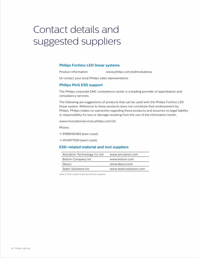
Philips Fortimo LED linear systems
Product information www.philips.com/ledmodulesna
Or contact your local Philips sales representative.
Philips PInS ESD support
The Philips corporate EMC competence center is a leading provider of approbation and
consultancy services.
The following are suggestions of products that can be used with the Philips Fortimo LED
linear system. Reference to these products does not constitute their endorsement by
Philips. Philips makes no warranties regarding these products and assumes no legal liability
or responsibility for loss or damage resulting from the use of the information herein.
www.innovationservices.philips.com/US
Phone:
+1 9788090483 (east coast)
+1 4154977939 (west coast)
ESD-related material and tool suppliers
Amcatron Technology Co Ltd www.amcatron.com
Botron Company Inc. www.botron.com
Desco www.desco.com
Static Solutions Inc www.staticsolutions.com
Table 8. ESD-related material and tool suppliers.
27
Fortimo LLS ES
Design-in Guide
Disclaimer
Disclaimer
The information in this guide is accurate at the time of writing. This guide is provided
“as is” without expressed or implied warranty of any kind. Neither Philips nor its agents
assume any liability for inaccuracies in this guide or losses incurred by use or misuse of
the information in this guide.
Philips will not be liable for any indirect, special, incidental or consequential damages
(including damages for loss of business, loss of profits or the like), whether based on breach
of contract, tort (including negligence), product liability or otherwise, even if Philips or its
representatives have been advised of the possibility of such damages.
© 2016 Philips Lighting Holding B.V. All rights reserved. Philips reserves the right to make changes in specifications and/or to discontinue any product at any time without notice or obligation and will not be liable for any consequences resulting from the use of this publication.
PLt-16270DG 11/16 philips.com
Philips LightingNorth America Corporation10275 W. Higgins RoadRosemont IL 60018Tel: 800-322-2086 Fax: 888-423-1882Customer/Technical Service: 800-372-3331OEM Support: 866-915-5886
Philips Lighting Canada Ltd.281 Hillmount Rd, Markham, ON, Canada L6C 2S3Tel. 800-668-9008