simplifying energy efficiency - abb · pdf filethere are two possible operational criteria for...
TRANSCRIPT

Lauri Tiainen, Teemu Jehkonen, Jan Fredrik hansen - drilling vessels such as semi-submersible drilling rigs and drillships are characterized by a high amount of installed electrical power for two main processes; drilling operations and dynamic positioning (dP). Both processes consume power of the order of several mWs and are powered from a common power supply consisting of multiple diesel generators in a redundant configuration. The total installed power is of around 50 MVA and is configured in several split subsystems, which can be interconnected when required. A variety of configurations exists; however, typically a semi submersible has a four-split arrangement with eight generators and eight thrusters, while a drill ship has a three-split arrangement with six generators and six thrusters.
Simplifying energy efficiency Azipod® CZ advantages for drilling vessels
T he drilling operation can consume as much as 10-15 MW and the dynamic posi-tioning operation as much as 30 MW in the most extreme weather conditions. Both
processes may be subject to large transient variations in their loads. Other loads on these vessels, such as accommodation and other auxiliaries, are minor when compared to these two largest processes. This article will focus on the thruster system used for dynamic positioning and its effects to the main power plant.
The availability to dynamic positioning is essential for operation of the vessel, as keeping position in all conditions is a prerequisite for drilling operations and also affects the safety of the vessel and persons on board, as well as the environmental emissions and risk for spill. For these reasons, thruster units are powered to keep the vessel in position consid-ering also the most extreme weather conditions permissible for safe operation. Furthermore, rules and regulations are developed so that failures of components or subsystems shall not affect station
keeping capabilities. For example, for DP classes 2 and 3, which apply to deepwater drilling units, the requirement is that the vessel maintains essential operations and keeps its position in the case of any single electrical failure (failures from fire and flooding are only covered by class 3). This means that the total rated power of all thrusters and power plant must be overdimensioned when compared to the actual loads experienced most of the time in operation. Simplified, a three-split system will be 3/2 or 150 percent rated, while a four-split system is 4/3 or 133 percent rated against power required after a single failure.
Vessel safety is, naturally, paramount and overrides efficiency and fuel oil consumption considerations. However, there remains potential to achieve energy savings and reduce installed power without compro-mising safety margins in any way, through introducing equipment such as the ABB’s Azipod CZ, which has been specially developed to maximize the output thrust force with minimum consumption of electric power.

1 Single line of a typical drillship with traditional mechanical thrusters
Drill ship configuration: typical exampleThere are two possible operational criteria for dimen-sioning main power plant and thrusters: transit and DP operation.
If DP operation is the main criterion, the size of the diesel engines selected will be determined by the power required for station-keeping and the required power for drilling operations. Here, the bollard pull capability of the thruster will be the decisive factor. If the transit speed is the dimensioning criterion, then it is the required power at the design speed (typically, this could be 10-12 knots) that sets the criteria, with the only addition being hotel and auxiliary loads. This would mean that the power requirement in bollard pull conditions is lower, as could be the case if the vessel is designed for DP operation in calmer waters. It is the designed permissible weather window and the consequence of single failure that decides the power requirements for DP operation.
With a more efficient thruster system, not only the thrusters, but the whole power plant could be adjusted.

2 Single line of a typical drillship with traditional Azipod CZ thrusters and suitable power plant
In Figure 1, a typical single line for a drillship is shown. The thruster motors consume 5.5 MW of power from the converters and the main engines each have 16 cylinders. For engines used in this kind of vessel power is usually somewhere in the range of 450-500 kW per cylinder. In this reference case we have assumed 500 kW per cylinder and that the DP operation would determine dimensions. The drilling equipment would be rated for power consumption around 8-10 MW. The reference case is shown with mechanical thrusters, as explained in the sections that follow.
With a more efficient thruster system, not only the thrusters, but the whole power plant could be adjusted. By using Azipod CZ, an efficiency gain is possible by achieving the same thrust force in bollard pull but consuming only 4.5 MW from the frequency converters. The result would be considerable savings in installed power. It should be noted that the numbers given here are assumptions and also depend on
other factors, such as ship design etc., which is not considered further here.
Figure 2 shows the single line example using 4.5MW power consuming Azipods. In this case, two fewer cylinders per engine, or a 12.5 percent reduction in installed generating power, could achieve the same output. Using 14-cylinder engines would thus cut fuel consumption, but should also reduce maintenance, given that this is typically based on the number of cylinders. It is, of course, also possible to consider other variations, such as installing different engine sizes to optimize diesel engine efficiency further. Saving space and money: reduced complexity with fewer componentsThe current Azipod CZ design provides a simple mechanical and electrical interface for the customer for design and construction, and the steering and propulsion drives are the main components to be integrated with the ship power system. Figure 3
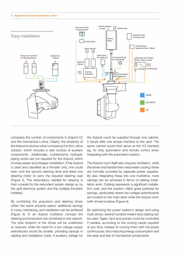
compares the number of components in Azipod CZ and the mechanical L-drive. Clearly, the simplicity of the Azipod is obvious when comparing it to the L-drive solution, which includes a vast number of auxiliary components. Additionally, cumbersome hydraulic piping works are not required for the Azipod, which involves easier and cheaper installation. If the Azipod is used and classified as a thruster only, one could even omit the second steering drive and leave one steering motor to carry the required steering load (Figure 4). The redundancy needed for steering is then covered by the redundant system design ie, by the split electrical system and the multiple thrusters installed.
By combining the propulsion and steering drives within the same physical space, additional savings in costs, interfacing, and installation can be achieved (Figure 5). In an Azipod multidrive concept the steering and propulsion are combined in one cabinet. The total footprint of the drives will be unaffected or reduced, while the need for a low voltage supply switchboard would be smaller, providing savings in cabling and installation costs. If auxiliary voltage for
the Azipod could be supplied through one cabinet, it would offer one simple interface to the yard. The same cabinet would then serve as the I/O interface eg, for ship automation and remote control when integrating with the automation system. The Azipod room itself also requires ventilation, while the drives and transformers need water cooling; these are normally provided by separate power supplies. By also integrating these into one multidrive, more savings can be achieved in terms of cabling instal-lation work. Cabling represents a significant installa-tion cost, and the solution offers great potential for savings, particularly where low voltage switchboards are located on the main deck while the Azipod room (with drives) is below (Figure 4).
By optimizing the power system’s design and using multi-drives, several hundred meters less cabling can be used. Again, fans and pumps could be controlled if needed, according to the cooling needs required at any time, instead of running them with full power continuously, thus reducing energy consumption and the wear and tear of mechanical components.
Auxiliary systems
Frequency ConverterFor Steering Motors
Azipod Aux.Cabinet
Instrument PanelCompressed Air
SteeringMotors
Drain PumpFor Shaft Seal
SteeringHydraulics
ElectricMotor
Instrument PanelFor Shaft Break
Motor FoundationsShaft Alignment
Steering GearExpansion Tank + Piping
Heat dissipationto amp.
Cooling Loop
Cooling Loop
Lubrication Unit: PumpsMotors, Filters, Coolers
Gravity Tanks
Motor Starters
Expansion TankFor Lower GearEasy installation
WATER
OIL
ELECTRICITY
3 Azipod CZ versus mechanical L-drive

PM motor efficiency: high result with effective motorsSince the propulsion system’s load profile has a huge impact on the vessel’s operating cost, the selection of the motor type alone is a significant factor in the energy efficiency and fuel consumption. The Azipod has the capacity to provide immediate full torque, which is available without any mechanical limitations or losses occurring in the transfer between motor and propeller, giving fast thrust and steering response. All of the heat produced by the motor is also cooled directly by sea water, which means the cooling capacity installed in the vessel can be reduced. The following drillship concept calculation shows the savings in real terms.
An evaluation is made to compare the yearly energy consumption of two different concepts of propulsion: 6 x Azipod CZ 4,5 MW thrusters and 6 x Mechanical L-drive 4,5 MW thrusters. The operational profile is based on the assumption that 5 percent of the vessels operations per year are at full speed. The remaining 95 percent of the time is dedicated to DP operation according to statistics provided for a similar DP vessel.
4 Azipod CZ as a thruster unit, with a single steering drive 5 Multidrive concept
By combining the propulsion and steering drives within the same physical space, additional savings in costs, interfacing, and installation can be achieved.

Meanwhile, 90 percent of DP operating, the thrusters function at lower than 100 rpm propeller speeds (ie, less than 15 percent of rated power). Mechanical, hydrody-namical, hull interaction, thermal and electrical losses are calculated based on load share.
The comparison shows that that Azipod CZ is about 7 percent more energy efficient on a drillship operation than the L-drive. This is due to the use of permanent magnet technology, which has a remarkably higher rate of efficiency when running at low RPM (Figure 5). If energy costs are given as $330 per MWh, this would reduce annual energy costs by about $480,000.
From small creeks to great rivers: PM auxiliary lossesThe following model presents losses in auxiliary systems, including those additional loads which are typically not taken into account when comparing different drive systems.
A mechanical thruster system will have a significant base load that is largely unchanged by the load on the propeller, and this in particular contributes to a relatively high contribution to energy losses when operating at partial loads (low powers), such as DP operation (Figure 8). Therefore, such components as cooling fans, lube oil pumps etc.. have been taken into account in this analysis. The aim was to compare ”apples to apples,” hence all losses that are equal
to the systems, such as transformer losses, electric power transmit losses etc., have been disregarded.
In conclusion, the analysis shows that there is the potential for annual energy savings of 3-7 percent using Azipod CZ propulsion.
Certain variables are unknown and have been omitted from the evaluation, such as losses in hydraulic steering gears, additional ventilation and the cooling needed for higher ambient losses from the mechanical thruster. Thus, the real difference should be even higher than calculated here.
Hydrodynamic benefitsIn addition to the direct differences in electrical effi-ciency already discussed, the Azipod CZ propeller shaft is installed with a 7-degree tilt angle in order to improve hydrodynamic efficiency and reduce thrust losses from hull interaction (Figure 9). The tilt angle also reduces interaction with other pontoons and thrusters, limiting further interaction with the hull (the Coandă effect) without the need for the tilted nozzles that are used in several mechanical thrusters which, while avoiding such effects, bring the disadvantage of increasing thrust losses. Hydrodynamically, this means a 4-8 percent advantage in thrust, compared with the tilted nozzle used with mechanical thrusters. A design that did not incorporate any tilt angle would lead to 10-30 percent loss of unit thrust.
6 A typical power system installation of a drilling semisubmersible rig
1
0.82
0.84
0.86
0.88
0.9
0.94
0.96
0.98
0.92
8060 120 140 160 180 200 220 240100Propeller RPM
Induction motorCZ motor effiency
7 Electric motor efficiency curves induction motor versus permanent magnet motor
Efficiency points were modeled with a VSD-motor simulation tool for 4.5 MW induction motor for thruster drive and Azipod C with permanent magnet motor.
Note: The efficiency curves are represented from 60 rpm propeller speed to full speed. 230 rpm point represents the transit mode

0
0.02
0.04
0.06
0.08
0.12
0.14
0.16
0.18
0.1
8060 120 140 160 180 200 220 240100Propeller RPM
L-drive propulsion/aux...CZ propulsion/aux losses...
Concluding remarksThere are a number of factors contributing to the greater efficiency of an Azipod CZ thruster over its mechanical counterpart, and the type of electric motor, mechanical connection, tilting and hydro-dynamic considerations all need to be considered in order to optimize energy efficiency and minimize thruster losses.
The potential of utilizing higher energy efficiency and power and energy savings depends on the design requirements and operational profile of the vessel, and should thus be checked case by case. The benefits of the Azipod CZ thruster can affect the design and dimensioning of the power plant for drilling vessels either by reducing the installed power capacity for same station keeping performance or by retaining power capacity while increasing the boundaries and margins of operations.
The energy and fuel saving potential of choosing the Azipod CZ solution established in the evaluation indicates that around 15 percent less energy can be used annually over a mechanical thruster. This is the result of electrical and hydrodynamical efficiency and will depend on propulsion load profile.
Lauri [email protected]
Teemu JehkonenABB [email protected]
Jan Fredrik [email protected]
9 Azipod CZ comes with a built-in tilt angle of the propeller shaft
8 Thruster auxiliary losses
Auxiliary losses in relation to actual power at specific load point. (LV electric drive additional losses 0.5 percent are included in Azipod CZ curve)