simple machines student activity book
TRANSCRIPT

Simple Machines
Student Activity Book
Name__________________________________________________________________
This activity book is yours to keep. Please put your name on it now. Your teacher will want
you to keep careful records of your investigations in this notebook.
Contents Simple Machines - Contents ........................................................................................................................ 1
Work ............................................................................................................................................................ 2
It’s All in the Balance ............................................................................................................................... 3-5
Moving the Fulcrum .................................................................................................................................... 6
Class 1 Levers .......................................................................................................................................... 7-8
Class 2 Levers ........................................................................................................................................ 9-10
Class 3 Levers ...................................................................................................................................... 11-12
Mechanical Advantage ......................................................................................................................... 13-14
Wheel and Axle ......................................................................................................................................... 15
Gears ......................................................................................................................................................... 16
Fixed Pulleys ........................................................................................................................................ 17-18
Movable Pulleys ................................................................................................................................... 19-20
Block and Tackle ....................................................................................................................................... 21
Pulley Systems and Mechanical Advantage .............................................................................................. 22
Inclined Plane ....................................................................................................................................... 23-25
Wedges ...................................................................................................................................................... 25
Screw Models ....................................................................................................................................... 26-27
Stairs .......................................................................................................................................................... 27
Glossary ..................................................................................................................................................... 28
Copyright 1997 by the Board of Cooperative Educational Services for the Second Supervisory District of Monroe and Orleans Counties. All rights reserved. No
part of this publication may be reproduced, stored in a retrieval system, or transmitted, in any form or by any means, electronic, mechanical photocopying,
recording, or otherwise, without the prior written permission of the publisher.
11/06

Work
When a force is used to move something, work is done. The amount of work depends on the amount of force and the distance moved.
Work = Force x Distance 1. In each of the following descriptions, tell why work is being done or why it is not being done. a. Lifting a bucket of water off the ground. _____________________________________
______________________________________________________________________
b. Riding a bicycle uphill. ___________________________________________________
______________________________________________________________________
c. Leaning against a wall. ___________________________________________________
______________________________________________________________________ d. Opening a door. _________________________________________________________
______________________________________________________________________
e. Sitting in a chair. ________________________________________________________
______________________________________________________________________
2. Work = Force x Distance Example: 20 gram-meters = 10 grams x 2 meters
a. How much work is done if an object weighing 5 grams (g) is lifted to a shelf 2 meters (m) high?
_______________________________________________________________________
b. If it takes a force of 15 g to move a cart 100 centimeters (cm), how much work is done?
_______________________________________________________________________ 3. Which requires more work, lifting 2 g up 10 cm or 3 g up 6 cm?
Explain. _____________________________________________________________________ ____________________________________________________________________________ ____________________________________________________________________________
____________________________________________________________________________ 2
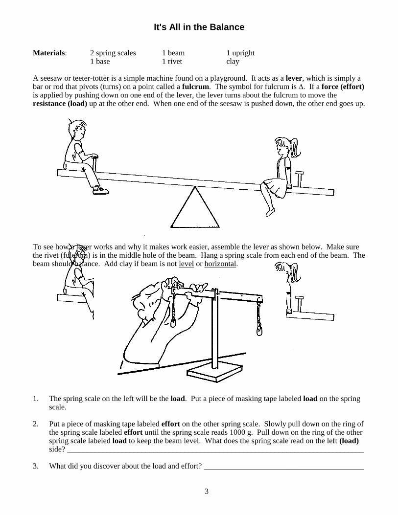
It's All in the Balance Materials: 2 spring scales 1 beam 1 upright 1 base 1 rivet clay
A seesaw or teeter-totter is a simple machine found on a playground. It acts as a lever, which is simply a bar or rod that pivots (turns) on a point called a fulcrum. The symbol for fulcrum is ∆. If a force (effort) is applied by pushing down on one end of the lever, the lever turns about the fulcrum to move the resistance (load) up at the other end. When one end of the seesaw is pushed down, the other end goes up. To see how a lever works and why it makes work easier, assemble the lever as shown below. Make sure the rivet (fulcrum) is in the middle hole of the beam. Hang a spring scale from each end of the beam. The beam should balance. Add clay if beam is not level or horizontal.
1. The spring scale on the left will be the load. Put a piece of masking tape labeled load on the spring
scale. 2. Put a piece of masking tape labeled effort on the other spring scale. Slowly pull down on the ring of
the spring scale labeled effort until the spring scale reads 1000 g. Pull down on the ring of the other spring scale labeled load to keep the beam level. What does the spring scale read on the left (load) side? ____________________________________________________________________________
3. What did you discover about the load and effort? _________________________________________
3

4. Repeat steps 1 and 2 for the lever shown below.
Effort is 1000 g
Load is g
5. What did you find? ________________________________________________________________ 6. Find out what happens to the effort when the load is closer to the fulcrum than the effort. The beam
will not balance. Pull the spring scale on the left down until the beam is level before completing the problem below.
Load is 1000 g
Effort is g
7. a. What happens to the amount of effort when the load is placed closer to the fulcrum than the effort? ____________________________________________________________________
____________________________________________________________________
b. How can a student weighing 60 pounds balance a student weighing 100 pounds on a seesaw?
____________________________________________________________________ ____________________________________________________________________
4

8. The distance from the fulcrum to the load or effort can be found mathematically. If a load of 800 g is placed 10 cm to the left of the fulcrum, where would an effort of 400 g be applied to the right of the fulcrum so the system would balance?
One way to find where to place the 400 g effort is to slide it along the beam until it balances. Another way is to use the equation below.
Distance x Load = Distance x Effort
Let A = distance the effort is applied in cm from the fulcrum 10 cm x 800 g = A x 400 g 8000 cm-g = A x 400 g 8000 cm-g = A 400 g 20 cm = A
9. Complete the following problems. Use the equation.
a. If a load of 600 g is placed 6 cm to the left of the fulcrum, where would an effort of 200 g be applied to the right side of the fulcrum to make the system balance?
Distance x Load = Distance x Effort
Let A = the distance the effort is applied in cm from the fulcrum
6 cm x 600 g = A x 200 g
b. If it takes an effort of 500 g applied 20 cm to the right of the fulcrum to balance a load 5 cm to the left of the fulcrum, what would the load be?
Let B = the load in g.
5 cm x B = 20 cm x 500 g
5

Moving the Fulcrum Materials: 2 spring scales 1 beam 1 upright 1 base 1 rivet
1. How much effort is needed to balance Lever A if the load is 1500 g? ________________________ 2. The fulcrum in Lever B has been moved one hole to the left of where it was placed in Lever A. Notice
that the load is still one hole to the left of the fulcrum. Will Lever B take more, less, or the same amount of effort to balance the load (1500 g) when compared with Lever A?
Predict:__________________________________________________________________________
To find out, assemble Lever B. It will not balance. Slowly pull the spring scale on the left (load) down until the beam is level or horizontal. Now pull down on the spring scale on the left with a force (load) of 1500 g. Hold the spring scale on the right (effort) still. What does the spring scale read on the right (effort) side? __________________________________________________________________________ 3. State a rule for applying a force (effort) on this type of lever that requires the least amount of effort to
balance the load.
________________________________________________________________________________ ________________________________________________________________________________
________________________________________________________________________________
________________________________________________________________________________
6

Class 1 Levers
Materials: 2 measuring tapes 1 base 1 rivet
2 spring scales 1 beam 1 upright
A class 1 lever has the fulcrum between the effort and the load. All the levers used so far are class 1 levers.
1. a. Shown below are examples of class 1 levers. Label the load, fulcrum and effort for each one.
b. List more class 1 levers______________________________________________________
_________________________________________________________________________
_________________________________________________________________________
_________________________________________________________________________
7
Figure A.
load effort
Figure B.

2. a. Assemble the class 1 lever as shown in Figure A. Pull down on the load (spring scale) with a
force of 3000 g. How much effort is required to make this lever horizontal (level)? ________
b. If a load moves upward 5 cm, how far downward does the effort move? _________________
Only measure the distance the effort moves. You do not have to use the spring scales to
answer this question.
3. a. Move the effort (spring scale) again as shown in Figure B. If a load of 3000 g is used, how
much effort must be applied? ______________________
b. If a load in Figure B moves upward 5 cm, how far downward does the effort move? _______
Remember, you do not have to use the spring scales.
4. Explain how the position of the fulcrum affects the effort needed to move the load.
_______________________________________________________________________________
_______________________________________________________________________________
_______________________________________________________________________________
5. Without measuring, how can you find how far downward the effort will move if you know how far
upward the load moves? Explain.
______________________________________________________________________________
______________________________________________________________________________
______________________________________________________________________________
8
load effort
load effort
5 cm ?

effort
load
Class 2 Levers Materials: 2 measuring tapes 1 base 1 rivet 2 spring scales 1 beam 1 upright A class 2 lever has the load between the fulcrum and the effort. 1. a. Shown below are examples of class 2 levers. Label the fulcrum, load and effort positions for each one.
b. List more class 2 levers._______________________________________________
_________________________________________________________________
__________________________________________________________________ Complete the chart below by following the directions in questions 2-4. Use the completed chart to help answer questions 5 and 6. Load Position
Load
Distance Load
Moves
Effort
Distance Effort
Moves
Hole 2
2000 g
5 cm
Hole 3
2000 g
5 cm
Hole 4
2000 g
5 cm
2. Put the fulcrum pin in hole 1. Hang the spring scale
labeled load from hole 2. Put the second spring scale labeled effort in hole 5 as shown.
a. Pull down with a force (load) of 2000 g. How much effort is needed to keep the beam
level?_______________ Record this number on the chart.
b. Hold the beam level. How far does the effort move if the load moves upward 5 cm? Find a way to answer this question and record the results on the chart. Remember, you do not have to use the spring scales.
c. Does the method used on page 8, number 5, work for a class 2 lever? ________
9
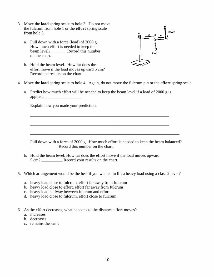
3. Move the load spring scale to hole 3. Do not move
the fulcrum from hole 1 or the effort spring scale from hole 5.
a. Pull down with a force (load) of 2000 g.
How much effort is needed to keep the beam level?_______ Record this number on the chart.
b. Hold the beam level. How far does the
effort move if the load moves upward 5 cm? Record the results on the chart.
4. Move the load spring scale to hole 4. Again, do not move the fulcrum pin or the effort spring scale.
a. Predict how much effort will be needed to keep the beam level if a load of 2000 g is applied.__________________
Explain how you made your prediction. __________________________________________________________________ __________________________________________________________________ _______________________________________________________________________
Pull down with a force of 2000 g. How much effort is needed to keep the beam balanced? _____________ Record this number on the chart.
b. Hold the beam level. How far does the effort move if the load moves upward
5 cm? __________ Record your results on the chart. 5. Which arrangement would be the best if you wanted to lift a heavy load using a class 2 lever?
a. heavy load close to fulcrum, effort far away from fulcrum b. heavy load close to effort, effort far away from fulcrum c. heavy load halfway between fulcrum and effort d. heavy load close to fulcrum, effort close to fulcrum
6. As the effort decreases, what happens to the distance effort moves?
a. increases b. decreases c. remains the same
10

Class 3 Levers Materials: 2 measuring tapes 1 base 1 rivet 2 spring scales 1 beam 1 upright A class 3 lever has the effort between the fulcrum and the load. 1. a. Shown below are examples of class 3 levers. Label the fulcrum, load and effort.
b. Name some other class 3 levers.__________________________________________________
____________________________________________________________________________
____________________________________________________________________________
Complete the chart below by following the directions in questions 2-4. Use the completed chart to help answer questions 5-7. Effort Position
Load
Distance Load
Moves
Effort
Distance Effort
Moves
Hole 2
500 g
5 cm
Hole 3
500 g
5 cm
Hole 4
500 g
5 cm
2. Put the fulcrum pin in hole 1. Put the spring scale
labeled effort in hole 2. Put the spring scale labeled load in hole 5 as shown.
a. Pull down on the spring scale (load) with a force of 500 g. You may have to hold the base with your hand to keep it from moving. How much effort does it take to keep the beam
level?______________ Record this number on the chart.
b. If the effort moves upward 5 cm, how far upward does the load move? ________ Record this distance on the chart.
11

3. Move the effort spring scale to hole 3. Do not move the fulcrum or the load spring scale.
a. Pull down on the spring scale load with a force
of 500 g. How much effort does it take to keep the beam level?_________ Record this number on the chart.
b. If the effort moves upward 5 cm, how far upward does the load move?__________ Record this distance on the chart.
4. Move the effort spring scale to hole 4. Do not move the fulcrum or the load spring scale.
a. Predict how much effort will be needed to keep the beam level if there is a load of 500 g.______ Predict how far the load will move if the effort moves 5 cm. ____________ Explain how you made your prediction.
_____________________________________________________________________________
_____________________________________________________________________________ _____________________________________________________________________________
b. Pull down on the spring scale (load) with a force of 500 g. How much effort does it take to keep the beam level? _________________ Record this number on the chart. How far will the load move if the effort moves 5 cm? _________________
5. What happens to the distance the load moves, as the effort is moved closer to the fulcrum?
a. increases b. decreases c. stays the same
6. What happens to the effort as it moves closer to the load?
a. increases b. decreases c. stays the same
7. What is the advantage of a class 3 lever?_______________________________________________
12

Mechanical Advantage
You found in previous activities that the effort needed to lift the load was sometimes less than the load. This
was done by placing a heavy load close to the fulcrum and the effort farther away from the fulcrum than the
load. The beam helped increase the smaller effort to enable it to lift the larger load. This ability of a lever to
increase the force (effort) applied to it is called its mechanical advantage (M.A.). The mechanical advantage
of a lever can be found by using this formula:
M.A. = Load ÷ Effort
Here is an example:
200 g
load effort
load
Load
Effort
2000 g
200 g
10
Find the mechanical advantages for questions 1-6.
Class 1 levers
1. 2.
100 g 300 g
effort effort load load
13
600 g 300 g
M.A.=
2000 g
M.A.=
M.A.=

Class 2 Levers
3. 100 g effort 4. 200 g effort
Class 3 Levers
5. 6.
effort 800 g effort 1000 g
load
7. What did you find out about the mechanical advantage of class 1 and class 2 levers?
_________________________________________________________________________________
_________________________________________________________________________________
_________________________________________________________________________________
8. What do you notice about the mechanical advantage of class 3 levers?
_________________________________________________________________________________
_________________________________________________________________________________
_________________________________________________________________________________
14
500 g 400 g
200 g 500 g

or 10:1
Wheel and Axle
In the windlass shown above, the axle is firmly attached to the wheel’s center so both the wheel and axle turn
together. A windlass is really a continuous lever rotating around a fulcrum.
Look at the diagram above. Notice that the fulcrum is located between the load (resistance) and the effort.
What class lever is a wheel and axle? __________
The purpose of a wheel and axle is to move a large resistance (load) with much less force (effort). To find
the mechanical advantage of a wheel and axle, find the ratio of the effort arm (radius of the wheel) to the load
arm (radius of the axle). Suppose the windlass has an effort arm 50 cm long and a load arm 5 cm. What is
the mechanical advantage?
Radius of Wheel (Effort Arm) = 50 cm = 10
Radius of Axle (Load Arm) 5 cm 1
The mechanical advantage is 10. When a force of 5 pounds is applied to the wheel, a force of 50 pounds is
applied to the axle.
Explain how a screwdriver and a steering wheel are examples of a wheel and axle, and how each makes work
easier.
____________________________________________________________________________________
____________________________________________________________________________________
____________________________________________________________________________________
Name some other devices that consist of a wheel and axle _____________________________________
____________________________________________________________________________________
____________________________________________________________________________________
15
M.A. =

Crank Handle
Gears
Materials: 1 egg beater masking tape
1. Line the crank handle up with the shaft. Put a piece of tape
on the blade that also lines up with the shaft.
Each team member will turn the crank handle while
the other members count how many times the marked
blade goes around when the handle goes around once.
Results:
Trial #1 Blades turn __________ times.
Trial #2 Blades turn __________ times.
Trial #3 Blades turn __________ times.
Trial #4 Blades turn __________ times.
Trial #5 Blades turn __________ times.
2. What did you find?_______________________________________________________________
______________________________________________________________________________
______________________________________________________________________________
3. Does an eggbeater increase speed or produce a greater mechanical advantage?
______________________________________________________________________________
How do you know? ______________________________________________________________
______________________________________________________________________________
4. When a small gear turns a large gear, force is increased. Look, below. The small gear has 6 teeth, the
large gear, 12 teeth. If the small gear is driving the large gear, how many times must the small gear go
around to make the large one turn once? ____________ What is the mechanical advantage the small gear
has when compared to the large gear?_____________
16
Shaft
Blade

effort
Fixed Pulleys
Materials: 2 measuring tapes 1 hook assembly string (60 cm)
2 spring scales 1 pulley
1 base 1 two-piece pulley upright
Assemble the materials as shown below.
1. How much effort is needed to lift a load of 2000 g? ____________________________________
2. Does the fixed pulley give an effort (mechanical) advantage? ____________________________
Explain: ______________________________________________________________________
_____________________________________________________________________________
_____________________________________________________________________________
3. Does the fixed pulley give a work advantage? ________________________________________
Explain: ______________________________________________________________________
_____________________________________________________________________________
_____________________________________________________________________________
4. Does the fixed pulley change the direction of the force? ________________________________
5. Does the fixed pulley change the amount of force needed to lift the load? __________________
6. If the load moves upward 5 cm, how far does the effort move downward? __________________
17
load
Make a small loop at
each end of the string.
Tie with an overhand
knot.

7. A fixed pulley acts like a class 1 lever. Look at the illustration below.
A fixed pulley can do no more than change the direction of a force. Like the seesaw whose fulcrum is in the
center, the effort arm and load (resistance) arm are of equal length. There is no useful mechanical advantage.
If the effort line is pulled downward 10 cm, the load moves upward 10 cm. This happens, for example,
when a flag is raised on a flag pole. The fixed pulley simply makes lifting the flag easier because pulling
down is easier than pulling up.
18
effort load

Movable Pulleys Materials: 2 measuring tapes 1 hook assembly string (60 cm) 2 spring scales 1 pulley 1 base 1 two-piece pulley upright
Assemble the materials as shown below.
effort load
1. How much effort is needed to lift a load of 2000 g? _________________________________________
2. Does the movable pulley give an effort (mechanical) advantage? _______________________________
___________________________________________________________________________________
Explain: ___________________________________________________________________________
___________________________________________________________________________________
___________________________________________________________________________________
3. Does the movable pulley give a work advantage? ___________________________________________
Explain: ___________________________________________________________________________ ___________________________________________________________________________________
___________________________________________________________________________________
4. Does a movable pulley change the direction of the force (effort) needed to pick up the load? _________
5. Does a movable pulley change the amount of force needed to lift the load? _______________________
19
Use string with loops at each
end from last activity.

6. If the load moves upward 5 cm, how far does the effort move? ____________________________
7. A movable pulley acts like a class 2 lever. Look at the illustration below.
A movable pulley offers a mechanical advantage of approximately 2. Like the wheelbarrow, the fulcrum is at one end, the effort at the other end, and the load halfway between the fulcrum and the effort. This means the effort will always move twice the distance the load moves, but will require an effort approximately equal to half the load.
20
effort
load

Block and Tackle Materials: 2 measuring tapes 1 base string (75 cm) 2 pulleys 1 hook assembly 2 spring scales 1 two-piece pulley upright Assemble the materials as shown below.
1. How much effort is needed to lift a load of 2000 g? _________________________________________
2. Does the fixed and movable pulley combination give an effort (mechanical) advantage? ____________
Explain ________________________________________________________________________________
__________________ 3. Does the fixed and movable pulley combination give a work advantage? ________________________
Explain
____________________________________________________________________________________________________________________________________________________________ 4. Does the fixed and movable pulley combination change the direction of the force (effort) needed to pick
up the load? ________________________________________________________________________
5. Does the fixed and movable pulley combination change the amount of force needed to lift the load?
___________________________________________________________________________________ 6. If the load moves upward 5 cm, how far does the effort move? ________________________________
7. A fixed and movable pulley combination is called a block and tackle.
21
Make a small loop at each end
of the string. Tie with an overhand
knot.
effort
load


Inclined Plane
Materials: Cart Assembly Inclined Plane Assembly 1 protractor 4 wheels 1 base 1 spring scale 2 dowels 1 board (ramp) masking tape 1 #64 rubber band 1 bottom half scissors 1 box of pulley upright 1 straw 1 ramp support washers
1. Cart Assembly
a. Unfold box and tape one end closed. b. Cut two 4 cm long pieces from the straw. c. Tape one 4 cm piece to the bottom of the box as shown below. Tape the second 4 cm piece of straw to the other end of the box.
Straw
d. Put one wheel on one end of a dowel. Slide the dowel through the straw on the box. Put another
wheel on the dowel as shown below. Repeat for the other end of the box.
e. Put the rubber band around the box just above the wheels as shown above.
f. Put enough washers (approximately 27-31) in the cart (box) so that the entire cart assembly
weighs 400 g. Close box top. Slip the hook on the spring scale under the rubber band at one end of the cart to weigh the cart.
23
Straw
Side View Bottom View
Bottom
Tape
Rubber band
End View

2. Inclined Plane Assembly a. Screw the upright into the base. b. Slide the ramp support onto the upright until it is approximately 4 cm from the top. c. Tighten both wing nuts. d. Slide the ramp support rod all the way through the hole in the board so that it touches the wood
(see below).
Front View Side View
3. a. It took an effort of 400 g to lift the cart assembly (load) that weighed 400 g. These numbers are
recorded in the chart below.
Angle
Load
Effort
Lifted
400 g
400 g
60°
400 g
45°
400 g
30°
400 g
b. Set the inclined plane (board) at 60° as shown below. Tighten wing nuts.
c. Use the spring scale to find the effort needed to slowly pull the cart assembly up the incline.
Record in the Effort column. 4 a. Repeat step 3b and 3c for 45°. b. Repeat step 3b and 3c for 30°. 5. How did the effort change as the slope (angle) changed? ________________________________ ____________________________________________________________________________
24
Ramp Support
Upright
Ramp
Base
Ramp Support
Ramp
Upright
Base

6. To find the mechanical advantage of any inclined plane, compare the length of the incline to the height
of the incline. For the inclined plane shown below, the cart would have to move up the slope 30 cm to lift the cart 15 cm. The mechanical advantage would be
30 cm 15 cm
Therefore, your 400 g cart could be pulled to the top with an effort of approximately 200 g.
How much effort must be used to pull a cart weighing 600 g to the top of the same inclined plane? Remember, the mechanical advantage is 2.
Wedges A wedge used to split wood is an example of two inclined planes placed “back to back.” Suppose a splitting wedge is 6 inches long and 2 inches thick. A sledge hammer would have to move the wedge 6 inches into the wood to split or pry the wood 2 inches apart. The mechanical advantage would be 3. What is the mechanical advantage of the wedge on the right? __________________________________ Which wedge would split wood more easily? _________________ Why? ________________________ ____________________________________________________________________________________ ____________________________________________________________________________________ Other wedges with fine edges, such as knives or razor blades press into the material to be cut, then the rest of the blade wedges or pries away a slice of the material.
Name five tools that are wedges.
1. 2. 3. ____________________
4. 5. _____________________
25
30 cm
15 cm
Wedge A
Mechanical Advantage is 3
Wedge B
= 2.

Screw Models Materials: 2 pencils blue crayon or marker scissors
activity Sheet #2 red crayon or marker tape 1. Follow the directions in Activity Sheet #2. 2. a. Place triangle A on top of triangle B as shown below. The triangles are like two inclined planes.
b. Which inclined plane would be easier to go up? ________________________________________ Why? _________________________________________________________________________ ______________________________________________________________________________
3. a. Place a pencil next to triangle A and tape it to the side of the triangle as shown below.
b. Wrap triangle A around the pencil until it is completely wrapped around the pencil. Be sure to wrap the triangle so the colored strip is on the outside. Tape the end so it does not unwind.
4. Use the other pencil and repeat step 3 for triangle B. 5. Does each wrapped triangle look like a screw? ____________________ 6. a. If the model screws were real, which screw, A or B, would take longer to screw into wood? _____
Why? _________________________________________________________________________ ______________________________________________________________________________
b. Which screw would be harder to screw into wood? ________ Why? _______________________ ______________________________________________________________________________ ______________________________________________________________________________
26

7. Remove the paper from each pencil. What shape best describes the paper when it has been removed from the pencil?
a. pulley b. spiral c. lever
8. What type of simple machine is a screw?______________________________________
Stairs Materials: activity sheet #3 scissors tape or glue 1. Follow the directions on Activity Sheet #3 to cut out and assemble model stairs. 2. Place the stairs on your desk or table so the shaded rectangles are on top. Look at the slope of the
line (inclined plane) on the side of the stairs. Would these stairs be easy or difficult to climb? ___________ Why? _____________________________________________________________________________
________________________________________________________________________________
___ 3. Place stairs on your desk or table so the unshaded rectangles are on top. Look at the slope of the line
(inclined plane) on the side of the stairs. Would these stairs be easy or difficult to climb?__________________ Why? _____________________________________________________
________________________________________________________________________________
___ 4. Which is easier to climb, an incline with a gentle slope or one with a steep slope? _____________
27
Glossary
axle - the rod or shaft on which a wheel revolves.
block and tackle - a combination of fixed and movable pulleys used to lift loads.
bolt - a shaft with an inclined plane wound around it.
effort - the force that is applied to a machine to produce an action.
force - a push or pull that makes something move, slow down, stop, or the
pressure that something exerts on an object.
friction - the resistance to motion that results when two surfaces rub against each
other.
fulcrum - the pivot or turning point of a lever.
gears - wheels with teeth used to turn other gears or be turned by other gears.
inclined plane - a simple machine that is a sloping surface. It is used to alter the effort and
distance involved in doing work.
lever - a simple machine that turns on a pivot, called a fulcrum, to produce a
useful movement.
load - the weight of an object that is moved by a machine, or the resistance to
movement that a machine must overcome.
mechanical advantage - the ability of a lever to increase the force (effort) applied to it.
pulley - a grooved wheel over which a rope, chain or belt passes.
screw - a shaft with an inclined plane wound around it.
system - a group of interacting objects.
thread - a spiraling inclined plane placed on the shaft of a screw (bolt) or on the
inside of a nut.
wedge - moving inclined plane(s).
wheel and axle - a circular disc attached to a shaft at its center.
work - the product of a force moving an object a measurable distance. Work =
force x distance.
28
