simple and accurate approach to implement the complex trans-conductance in time- domain simulators...
TRANSCRIPT

Simple and Accurate Approach to Implement Simple and Accurate Approach to Implement the Complex Trans-Conductance in Time-the Complex Trans-Conductance in Time-
Domain SimulatorsDomain Simulators
M. Homayouni, D. Schreurs, and M. Homayouni, D. Schreurs, and
B. NauwelaersB. Nauwelaers
K.U.Leuven, BelgiumK.U.Leuven, Belgium

OutlineOutline
• Introduction to Table-Based ModelIntroduction to Table-Based Model• Microwave and mm-Wave IssuesMicrowave and mm-Wave Issues• ImplementationImplementation
• Linear ModelLinear Model• Non-Linear ModelNon-Linear Model
• ConclusionConclusion• AcknowledgementAcknowledgement

Introduction to Table-Based ModelIntroduction to Table-Based Model
• Layout and equivalent circuit of CMOS FinFET transistor.Layout and equivalent circuit of CMOS FinFET transistor.

Introduction to Table-Based ModelIntroduction to Table-Based Model
• Equivalent Circuit• Intrinsic Network: Parameters that are bias-dependent, representing active
channel.• Extrinsic Network: Parasitic elements that are bias-independent, originating
from layout pads.

Introduction to Table-Based ModelIntroduction to Table-Based Model
• Model (equivalent circuit parameters) is extracted from Model (equivalent circuit parameters) is extracted from measurements carried out on actual device.measurements carried out on actual device.
• DC-measurementsDC-measurements• S-parameter measurementsS-parameter measurements• Thermal measurementsThermal measurements• Noise measurementsNoise measurements
– Intrinsic Network ParametersIntrinsic Network Parameters• Bias-dependentBias-dependent• Extracted from S-parameters at hot bias condition (Vgs and Vds non-zero)Extracted from S-parameters at hot bias condition (Vgs and Vds non-zero)• Tabulated in table-files Tabulated in table-files
– Extrinsic Network Parameters Extrinsic Network Parameters • Bias-independentBias-independent• Extracted from S-parameters at cold bias condition (Vds=0)Extracted from S-parameters at cold bias condition (Vds=0)• Tabulated in table-files Tabulated in table-files

Microwave and mm-Wave IssuesMicrowave and mm-Wave Issues
• Complex Trans-ConductanceComplex Trans-Conductance• gm, represents the gaingm, represents the gain• represents the channel time-delayrepresents the channel time-delay
Complex Trans-conductance
Microwave and mm-Wave IssuesMicrowave and mm-Wave Issues
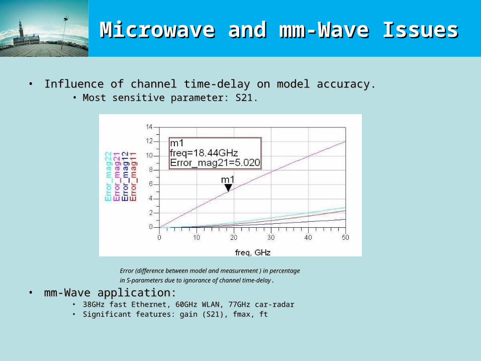
• Influence of channel time-delay on model accuracy.Influence of channel time-delay on model accuracy.• Most sensitive parameter: S21.Most sensitive parameter: S21.
Error (difference between model and measurement ) in percentage Error (difference between model and measurement ) in percentage
in S-parameters due to ignorance of channel time-delayin S-parameters due to ignorance of channel time-delay..
• mm-Wave application:mm-Wave application:• 38GHz fast Ethernet, 60GHz WLAN, 77GHz car-radar38GHz fast Ethernet, 60GHz WLAN, 77GHz car-radar• Significant features: gain (S21), fmax, ftSignificant features: gain (S21), fmax, ft

ImplementationImplementation
• Do microwave software support complex trans-conductance (time-delay)?
ADS (Advance Design System) Yes
Spectre (Cadence) No
Verilog-A No
Spice No
Complex trans-conductance in ADSGain: gm = 45mS time delay: t = 5.2psec

ImplementationImplementation
• represents the channel time-delayrepresents the channel time-delay
• Virtual implementation of time-delayVirtual implementation of time-delay• Introduction of transmission lineIntroduction of transmission line
– @ Gate terminal to delay the sampling voltage@ Gate terminal to delay the sampling voltage– @ Drain terminal to delay the current of voltage-controlled @ Drain terminal to delay the current of voltage-controlled
current source (VCCS)current source (VCCS)
Delayed Voltage

ImplementationImplementation
• How to determine and implement the t-line?How to determine and implement the t-line?• T-line should be terminated with match-load to guarantee no T-line should be terminated with match-load to guarantee no
reflection.reflection.
• Input impedance of t-line should be orders of magnitudes larger than Input impedance of t-line should be orders of magnitudes larger than impedance seen from connection point (Zin should be much larger impedance seen from connection point (Zin should be much larger than Zout) .than Zout) .
• Electrical length of t-line corresponds to time-delay.Electrical length of t-line corresponds to time-delay.
Zin
Zout

ImplementationImplementation
• Implementation Issues for SimulatorsImplementation Issues for Simulators• T-lines are not very convenient for time-domain simulators.T-lines are not very convenient for time-domain simulators.• T-lines are approximated by lumped LC-networkT-lines are approximated by lumped LC-network
– Simpler to extract the valuesSimpler to extract the values– Simpler to develop them in modelSimpler to develop them in model– Limited in terms of frequency rangeLimited in terms of frequency range

ImplementationImplementation
• Approximate LC-NetworkApproximate LC-Network• If If then the LC-network is performing as a t-line that delays the then the LC-network is performing as a t-line that delays the
input signal.input signal.
• is in order of tenth of psec.is in order of tenth of psec.• Z0 is in order of MZ0 is in order of M• In our case (FinFET transistor):In our case (FinFET transistor):
– 300MHz < f < 50GHz300MHz < f < 50GHz
– psec psec
02 2 2
0 0
11
(1 )jout
in
V Zj e
V Z LCZ j L j
< 0.3333 , acceptable but limitedin terms of frequency range

ImplementationImplementation
• Comparison between Comparison between model and model and measurement in both measurement in both cases, with time-cases, with time-delay and without delay and without
time-delaytime-delay..• Accuracy of model is Accuracy of model is
improved due to improved due to implementation of implementation of time-delay.time-delay.
Improvement in model accuracy

ImplementationImplementation
• Non-linear table-based model
Integration
ImplementationImplementation
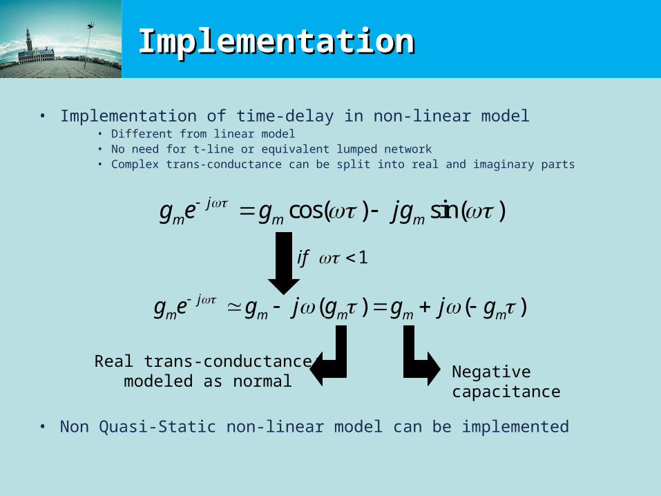
• Implementation of time-delay in non-linear model• Different from linear model• No need for t-line or equivalent lumped network• Complex trans-conductance can be split into real and imaginary parts
• Non Quasi-Static non-linear model can be implemented
( ) ( )jm m m m mg e g j g g j g
cos( ) sin( )jm m mg e g jg
1if
Real trans-conductance: modeled as normal
Negative capacitance

ConclusionConclusion
• Channel time-delay is significant at microwave and mm-Channel time-delay is significant at microwave and mm-wave frequencies.wave frequencies.
• Accurate technique was introduced to introduce complex Accurate technique was introduced to introduce complex trans-conductance in time-domain simulators.trans-conductance in time-domain simulators.
• Simple and accurate approximation was introduced to Simple and accurate approximation was introduced to ease the time-delay implementation in model for time-ease the time-delay implementation in model for time-domain simulators.domain simulators.
• Simple method was introduced to implement non quasi-Simple method was introduced to implement non quasi-static non-linear table-based models.static non-linear table-based models.

Acknowledgements
• Nano-RF project IST-027150
• FinFET team at IMEC
• Andries Scholten from NXP