simp kin radiation shielding
DESCRIPTION
It`s SimpkinTRANSCRIPT
1
2007 AAPM Summer School2007 AAPM Summer School
Overview and Basis of Overview and Basis of Design for NCRP Report 147Design for NCRP Report 147
Douglas J. Simpkin, Ph.D.Aurora St. Luke’s Medical Ctr
Milwaukee, [email protected]
http://www.geocities.com/djsimpkin/
2
Welcome To The Welcome To The Next GenerationNext Generation**• NCRP Report No. 147: Structural Shielding
Design for X-ray Imaging• AAPM Task Group 108: Shielding for
PET/CT Facilities• NCRP Report No. 151: Structural Shielding
Design for Megavoltage Radiotherapy Facilities
*Of shielding design, that is!
3
NotesNotes• NCRP Report No. 147 was a committee
report– I take credit for the good stuff, blame the others
for the bad• NCRP Report No. 147 was our take on
“best practice” at one moment in time…– It’ll need constant revision
• But we hope that our methods will be rigorous enough to last a few years!
• I’ll point out those areas that I recognize as requiring a “fresh view”
4
History of Diagnostic XHistory of Diagnostic X--ray ray Shielding DesignShielding Design
• NBS Handbook 60 (1955) & Braestrup & Wykoff Health Physics Text (1958)
• NCRP Reports 34 (1972) & 49 (1976)– Standard for specifying shielding for
past 30 years– Limitations noted by mid ‘70s
• AAPM Task Group 9 formed 1989 • NCRP/ AAPM Task Group 1992
5
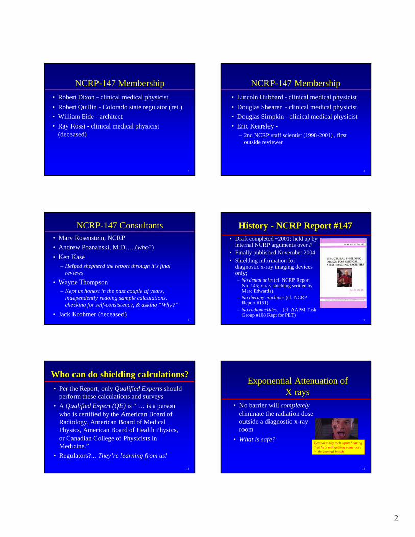
History History –– NCRP/ AAPM Task Group 1992-2004
• Measured/confirmed fundamental shielding data– Workloads– Transmission
• Refined shielding theory• Published results along the
way– 16 refereed publications,
including 5 in Medical Physics & 6 in Health Physics
– >31 invited lectures given by the members at AAPM, HPS, CRCPD, RSNA, AAPM & HPS Chapters, etc
Ben Archer, Linc Hubbard, Bob Dixon & I meet at Bob’s beach house (off season... Can you tell the Yankees from the Southerners?)
6
NCRP-147 Cochairs• Joel Gray
– clinical/ industry medical physicist
• Ben Archer– clinical
medical physicist
2
7
NCRP-147 Membership• Robert Dixon - clinical medical physicist• Robert Quillin - Colorado state regulator (ret.).• William Eide - architect• Ray Rossi - clinical medical physicist
(deceased)
8
NCRP-147 Membership• Lincoln Hubbard - clinical medical physicist• Douglas Shearer - clinical medical physicist• Douglas Simpkin - clinical medical physicist• Eric Kearsley -
– 2nd NCRP staff scientist (1998-2001) , first outside reviewer
9
NCRP-147 Consultants• Marv Rosenstein, NCRP• Andrew Poznanski, M.D…..(who?)• Ken Kase
– Helped shepherd the report through it’s final reviews
• Wayne Thompson– Kept us honest in the past couple of years,
independently redoing sample calculations, checking for self-consistency, & asking “Why?”
• Jack Krohmer (deceased)10
History History -- NCRP Report #147NCRP Report #147• Draft completed ~2001; held up by
internal NCRP arguments over P• Finally published November 2004• Shielding information for
diagnostic x-ray imaging devices only; – No dental units (cf. NCRP Report
No. 145; x-ray shielding written by Marc Edwards)
– No therapy machines (cf. NCRP Report #151)
– No radionuclides… (cf. AAPM Task Group #108 Rept for PET)
11
Who can do shielding calculations?Who can do shielding calculations?• Per the Report, only Qualified Experts should
perform these calculations and surveys• A Qualified Expert (QE) is “ … is a person
who is certified by the American Board of Radiology, American Board of Medical Physics, American Board of Health Physics, or Canadian College of Physicists in Medicine.”
• Regulators?... They’re learning from us!
12
Exponential Attenuation of Exponential Attenuation of X raysX rays
• No barrier will completelyeliminate the radiation dose outside a diagnostic x-ray room
• What is safe?Typical x-ray tech upon hearing that he’s still getting some dose in the control booth
3
13
Controlled & Uncontrolled AreasControlled & Uncontrolled Areas• Controlled areas are occupied by
employees/ staff whose occupational radiation dose is monitored
• Uncontrolled areas occupied by individuals such as patients, visitors to the facility, and employees who do not work routinely with or around radiation sources. Areas adjacent to, but not part of, the x-ray facility are also uncontrolled areas.
14
Design Goal, Design Goal, PP
• P = permitted radiation level in the occupied area.
• P must be consistent with NRCP Report 116, which limits the effective dose equivalent – Which can’t be measured– Is highly photon energy-dependent
• P for NCRP-147 is a kerma value• P for NCRP-151 (with neutrons) is a dose
equivalent
15
Design Goal, Design Goal, PP
Factor of 5 decrease
Factor of 10 decreaseEffect
1 mGy/y = 0.02 mGy/wk
Fraction ( =½) of 10 mGy/y limit for new operations = 5 mGy/y (~matches fetal dose limit)= 0.1 mGy/wk
NCRP-1472004
5 mGy/y = 0.1 mGy/wk
50 mGy/y = 1 mGy/wk
NCRP-491976
Uncontrolled AreaControlled Area
16
NCRP 0.25 NCRP 0.25 mSv/ymSv/y General Public Limit?General Public Limit?
NCRP-116 sayeth unto us:“...whenever the potential exists for exposure of an individual member of the public to exceed 25 percent of the annual effective dose limit as a result of irradiation attributable to a single site, the site operator should ensure that the annual exposure of the maximally exposed individual, from all man-made exposures (excepting that individual's medical exposure), does not exceed 1 mSv on a continuous basis. Alternatively, if such an assessment is not conducted, no single source or set of sources under one control should result in an individual being exposed to more than 0.25 mSv annually.”
17
NCRP Statement 10 (2004)• In Statement No. 10 Recent Applications of
of the NCRP Public Dose Limit Recommendation for Ionizing Radiation (December ‘04) the NCRP reinforced that “An effective dose … that does not exceed 1 mSv y-1 is justified for the conservatively safe assumptions used in the recommended shielding design methodology.”
• Statement No. 10 is available at www.ncrp.com18
Uncontrolled Uncontrolled PP=0.1 mGy/y=0.1 mGy/y will will satisfy 0.25 mSv/ysatisfy 0.25 mSv/y
• Ignoring patient attenuation• Assuming perpendicular beam incidence• Ignoring attenuating items in room (e.g. Pb
aprons and fluoro drapes, etc.)• Assuming worst-case leakage levels• Assuming conservatively large beam areas
for worst-case scatter calculations
4
19
Uncontrolled Uncontrolled PP=0.1 mGy/y=0.1 mGy/y will will satisfy 0.25 mSv/ysatisfy 0.25 mSv/y
• Assuming conservatively high occupancy factors
• Pb sheets come in quantized thicknesses (e.g. 1/32 inch, 1/16 inch, etc). Using the next greater thickness will shield to much lower levels than P
• Assuming minimum distances from source to personnel in occupied areas
20
Uncontrolled Uncontrolled PP=0.1 mGy/y=0.1 mGy/y will will satisfy 0.25 mSv/ysatisfy 0.25 mSv/y
• At <50 keV, the Effective Dose Equivalent is a small fraction of the kerma (due to shielding of deep organs by overlying tissues)
21
Occupancy Factor, Occupancy Factor, TT• Traditionally, shielding designers have
allowed for partial occupancy in shielded areas, with T the “occupancy” factor
• T is the fraction of the beam-on time a shielded area is occupied by an individualan individual
•• Shielding task: a barrier is acceptable if Shielding task: a barrier is acceptable if it decreases the kerma behind the barrier it decreases the kerma behind the barrier to to P/TP/T
• If T<1, the “full-time dose” will be P/T22
Recommended Occupancy FactorsRecommended Occupancy FactorsOffices, labs, pharmacies, receptionist areas, attendedwaiting rooms, kids’ play areas, x-ray rooms, filmreading areas, nursing stations, x-ray control rooms
1
Patient exam & treatment rooms ½
Corridors, patient rooms, employee lounges, staff restrooms 1/5
Corridor doors 1/8
Public toilets, vending areas, storage rooms, outdoorareas w/ seating, unattended waiting rooms, patientholding
1/20
Outdoors, unattended parking lots, attics, stairways,unattended elevators, janitor’s closets 1/40
236
Radiation Worker
P = 5 mGy y -1 T = 1
VisitorP = 1 mGy y -1
T = 1/20
Lawyer’s Office (not associated with X-Ray Clinic)
ReceptionistP = 1 mGy y -1
T = 1
Members of the PublicP = 1 mGy y -1T = 1
X-Ray Clinic X-Ray Clinic Waiting Area
24
XX--ray Beam Transmissionray Beam Transmission• For a given x-ray
spectrum, the Transmission, B,through a barrier of thickness x is the ratio of kerma with & without the barrier
)0()()(
KxKxB =
K(0)
K(x)
x
Radiation Source
Kerma detector
5
25
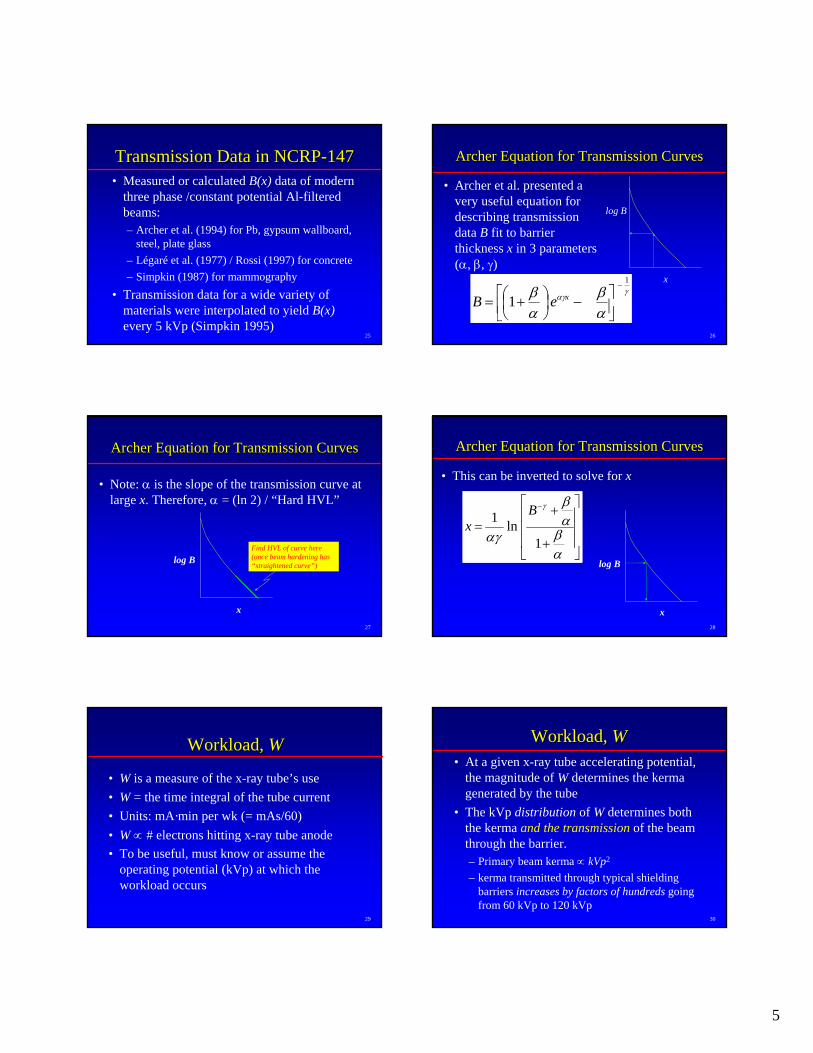
Transmission Data in NCRPTransmission Data in NCRP--147147• Measured or calculated B(x) data of modern
three phase /constant potential Al-filtered beams:– Archer et al. (1994) for Pb, gypsum wallboard,
steel, plate glass– Légaré et al. (1977) / Rossi (1997) for concrete – Simpkin (1987) for mammography
• Transmission data for a wide variety of materials were interpolated to yield B(x)every 5 kVp (Simpkin 1995)
26
Archer Equation for Transmission CurvesArcher Equation for Transmission Curves
• Archer et al. presented a very useful equation for describing transmission data B fit to barrier thickness x in 3 parameters (α, β, γ)
γαγ
αβ
αβ
1
1−
⎥⎦⎤
⎢⎣⎡ −⎟
⎠⎞
⎜⎝⎛ += xeB
x
log B
27
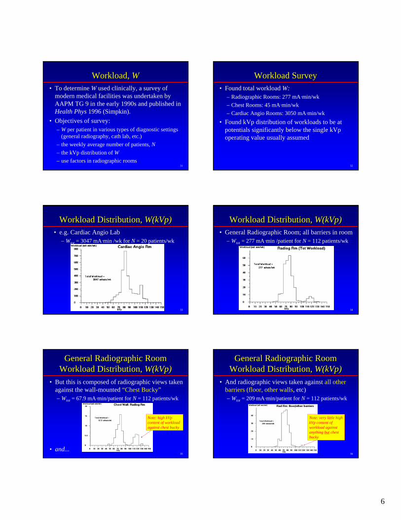
Archer Equation for Transmission CurvesArcher Equation for Transmission Curves
• Note: α is the slope of the transmission curve at large x. Therefore, α = (ln 2) / “Hard HVL”
x
log BFind HVL of curve here (once beam hardening has “straightened curve”)
28
Archer Equation for Transmission CurvesArcher Equation for Transmission Curves
• This can be inverted to solve for x
⎥⎥⎥
⎦
⎤
⎢⎢⎢
⎣
⎡
+
+=
−
αβαβ
αγ
γ
1ln1 B
x
x
log B
29
Workload, Workload, WW
• W is a measure of the x-ray tube’s use• W = the time integral of the tube current• Units: mA·min per wk (= mAs/60)• W ∝ # electrons hitting x-ray tube anode• To be useful, must know or assume the
operating potential (kVp) at which the workload occurs
30
Workload, Workload, WW• At a given x-ray tube accelerating potential,
the magnitude of W determines the kerma generated by the tube
• The kVp distribution of W determines both the kerma and the transmission of the beam through the barrier.– Primary beam kerma ∝ kVp2
– kerma transmitted through typical shielding barriers increases by factors of hundreds going from 60 kVp to 120 kVp
6
31
Workload, Workload, WW• To determine W used clinically, a survey of
modern medical facilities was undertaken by AAPM TG 9 in the early 1990s and published in Health Phys 1996 (Simpkin).
• Objectives of survey:– W per patient in various types of diagnostic settings
(general radiography, cath lab, etc.)– the weekly average number of patients, N– the kVp distribution of W– use factors in radiographic rooms
32
Workload SurveyWorkload Survey• Found total workload W:
– Radiographic Rooms: 277 mA·min/wk – Chest Rooms: 45 mA·min/wk – Cardiac Angio Rooms: 3050 mA·min/wk
• Found kVp distribution of workloads to be at potentials significantly below the single kVp operating value usually assumed
33
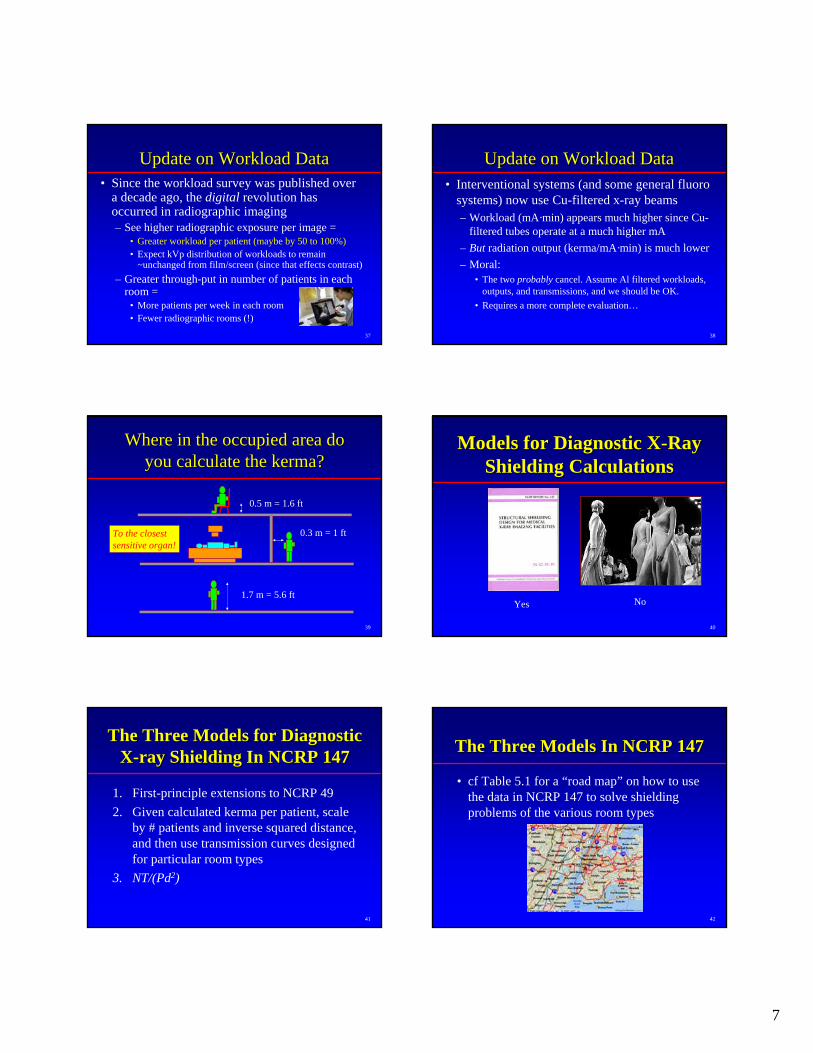
Workload Distribution, Workload Distribution, W(kVp)W(kVp)• e.g. Cardiac Angio Lab
– Wtot = 3047 mA·min /wk for N = 20 patients/wk
34
Workload Distribution, Workload Distribution, W(kVp)W(kVp)• General Radiographic Room; all barriers in room
– Wtot = 277 mA·min /patient for N = 112 patients/wk
35
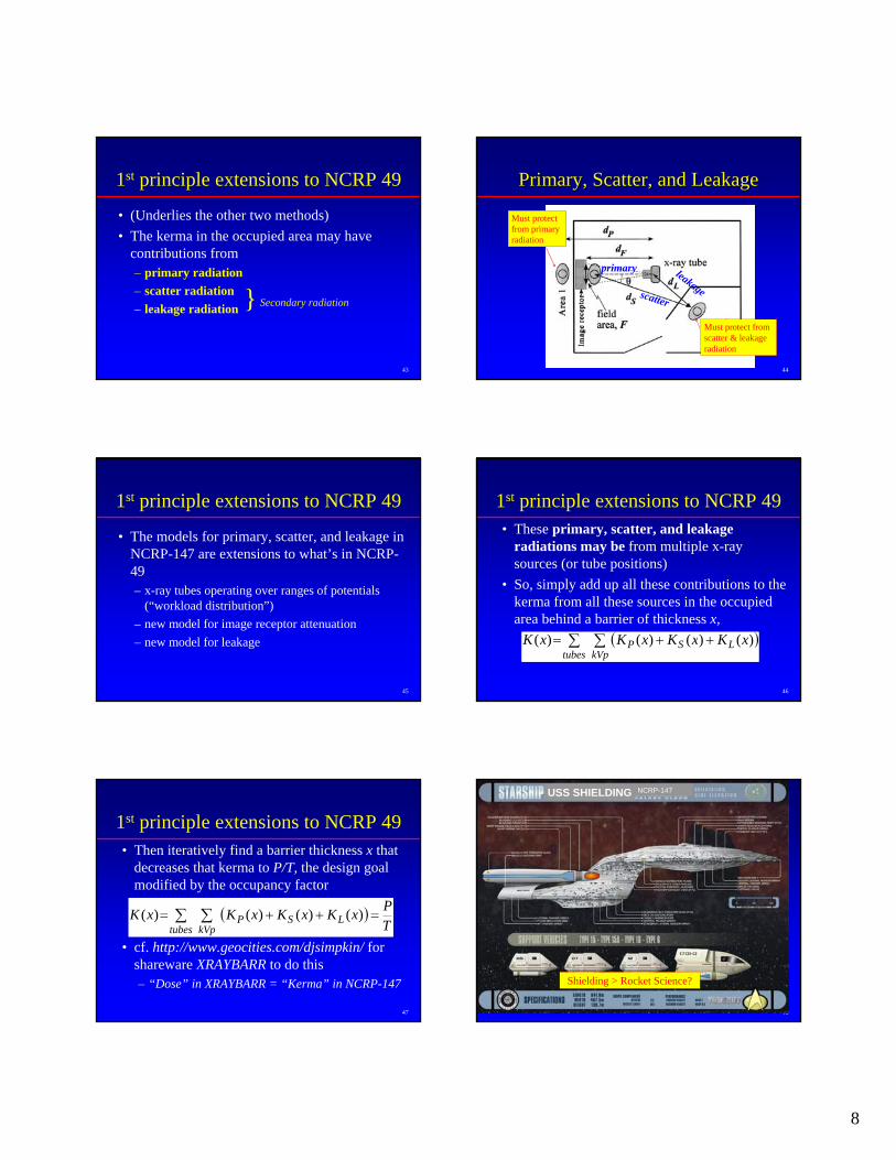
General Radiographic Room General Radiographic Room Workload Distribution, Workload Distribution, W(kVp)W(kVp)
• But this is composed of radiographic views taken against the wall-mounted “Chest Bucky”– Wtot = 67.9 mA·min/patient for N = 112 patients/wk
• and...
Note: high kVp content of workload against chest bucky
36
General Radiographic Room General Radiographic Room Workload Distribution, Workload Distribution, W(kVp)W(kVp)
• And radiographic views taken against all other barriers (floor, other walls, etc)– Wtot = 209 mA·min/patient for N = 112 patients/wk
Note: very little high kVp content of workload against anything but chest bucky
7
37
Update on Workload DataUpdate on Workload Data• Since the workload survey was published over
a decade ago, the digital revolution has occurred in radiographic imaging– See higher radiographic exposure per image =
• Greater workload per patient (maybe by 50 to 100%)• Expect kVp distribution of workloads to remain
~unchanged from film/screen (since that effects contrast)– Greater through-put in number of patients in each
room =• More patients per week in each room• Fewer radiographic rooms (!)
38
Update on Workload DataUpdate on Workload Data• Interventional systems (and some general fluoro
systems) now use Cu-filtered x-ray beams– Workload (mA·min) appears much higher since Cu-
filtered tubes operate at a much higher mA– But radiation output (kerma/mA·min) is much lower – Moral:
• The two probably cancel. Assume Al filtered workloads, outputs, and transmissions, and we should be OK.
• Requires a more complete evaluation…
39
Where in the occupied area do Where in the occupied area do you calculate the you calculate the kermakerma??
1.7 m = 5.6 ft
0.3 m = 1 ft
0.5 m = 1.6 ft
To the closest sensitive organ!
40
Models for Diagnostic XModels for Diagnostic X--Ray Ray Shielding CalculationsShielding Calculations
Yes No
41
The Three Models for Diagnostic The Three Models for Diagnostic XX--ray Shielding In NCRP 147ray Shielding In NCRP 147
1. First-principle extensions to NCRP 492. Given calculated kerma per patient, scale
by # patients and inverse squared distance, and then use transmission curves designed for particular room types
3. NT/(Pd2)
42
The Three Models In NCRP 147The Three Models In NCRP 147
• cf Table 5.1 for a “road map” on how to use the data in NCRP 147 to solve shielding problems of the various room types
8
43
1st principle extensions to NCRP 49
• (Underlies the other two methods)• The kerma in the occupied area may have
contributions from– primary radiation– scatter radiation– leakage radiation Secondary radiation}
44
Primary, Scatter, and LeakagePrimary, Scatter, and Leakage
Must protect from scatter & leakage radiation
Must protect from primary radiation
primary
scatter
leakage
45
1st principle extensions to NCRP 49
• The models for primary, scatter, and leakage in NCRP-147 are extensions to what’s in NCRP-49 – x-ray tubes operating over ranges of potentials
(“workload distribution”)– new model for image receptor attenuation– new model for leakage
46
1st principle extensions to NCRP 49• These primary, scatter, and leakage
radiations may be from multiple x-ray sources (or tube positions)
• So, simply add up all these contributions to the kerma from all these sources in the occupied area behind a barrier of thickness x,
( )∑ ∑ ++=tubes kVp
LSP xKxKxKxK )()()()(
47
1st principle extensions to NCRP 49• Then iteratively find a barrier thickness x that
decreases that kerma to P/T, the design goal modified by the occupancy factor
• cf. http://www.geocities.com/djsimpkin/ for shareware XRAYBARR to do this– “Dose” in XRAYBARR = “Kerma” in NCRP-147
( )∑ ∑ =++=tubes kVp
LSP TPxKxKxKxK )()()()(
48
USS SHIELDING
Shielding > Rocket Science?
NCRP-147
9
49
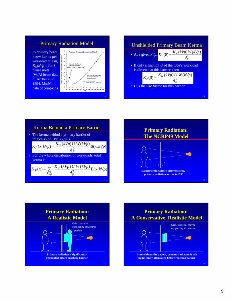
Primary Radiation ModelPrimary Radiation Model• In primary beam,
know kerma per workload at 1 m, KW(kVp) , for 3 phase units (W/Al beam data of Archer et al. 1994, Mo/Mo data of Simpkin)
Primary Kerma at 1 m per workload
50
Unshielded Primary Beam KermaUnshielded Primary Beam Kerma
• At a given kVp,
• If only a fraction U of the tube’s workload is directed at this barrier, then
• U is the use factor for this barrier
2
)()()0(P
WP d
kVpWkVpKK =
2
)()()0(P
WP d
kVpWUkVpKK =
51
KermaKerma Behind a Primary BarrierBehind a Primary Barrier• The kerma behind a primary barrier of
transmission B(x, kVp) is
• For the whole distribution of workloads, total kerma is
),()()(),( 2 kVpxBd
kVpWUkVpKkVpxKP
WP =
),()()()( 2 kVpxBd
kVpWUkVpKxKP
W
kVpP ∑=
52
Primary Radiation:Primary Radiation:The NCRP49 ModelThe NCRP49 Model
Barrier of thickness x decreases raw primary radiation kerma to P/T
x
53
Primary Radiation:Primary Radiation:A Realistic ModelA Realistic Model
Primary radiation is significantly attenuated before reaching barrier
Grid, cassette, supporting structures
patient
54
Primary Radiation:Primary Radiation:A Conservative, Realistic ModelA Conservative, Realistic Model
Even without the patient, primary radiation is stillsignificantly attenuated before reaching barrier
Grid, cassette, maybe supporting structures
10
55
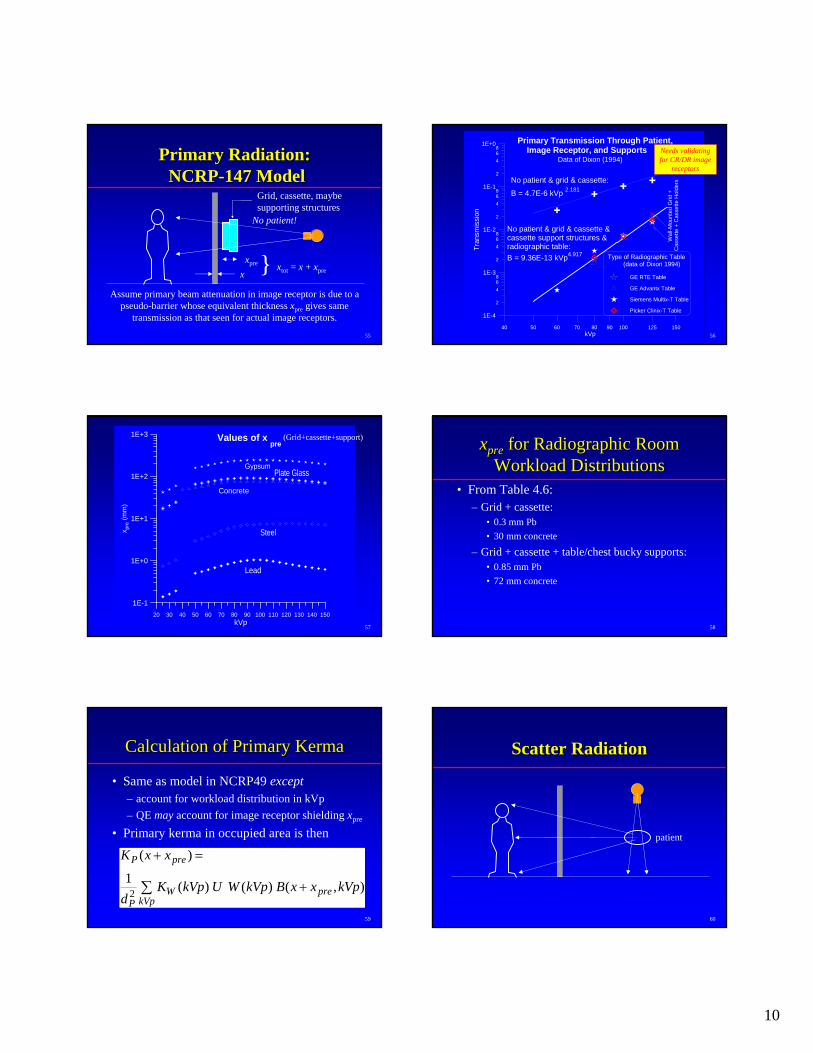
Primary Radiation:Primary Radiation:NCRPNCRP--147 Model147 Model
Assume primary beam attenuation in image receptor is due to a pseudo-barrier whose equivalent thickness xpre gives same
transmission as that seen for actual image receptors.
Grid, cassette, maybe supporting structures
xxpre } xtot = x + xpre
No patient!
5640 50 60 70 80 90 100 125 150
kVp
2
468
2
468
2
468
2
468
1E-4
1E-3
1E-2
1E-1
1E+0
Tran
smis
sion
No patient & grid & cassette &cassette support structures &radiographic table:B = 9.36E-13 kVp4.917
Primary Transmission Through Patient, Image Receptor, and Supports
Type of Radiographic Table (data of Dixon 1994)
GE RTE Table
GE Advantx Table
Siemens Multix-T Table
Picker Clinix-T Table
Wal
l-Mou
nted
Grid
+C
asse
tte +
Cas
sette
Hol
dersNo patient & grid & cassette:
B = 4.7E-6 kVp 2.181
Data of Dixon (1994)Needs validating for CR/DR image
receptors
57
20 30 40 50 60 70 80 90 100 110 120 130 140 150kVp
1E-1
1E+0
1E+1
1E+2
1E+3
x pre
(mm
)
Plate GlassGypsum
Concrete
Steel
Lead
Values of x pre
(Grid+cassette+support)
58
xxprepre for Radiographic Room for Radiographic Room Workload DistributionsWorkload Distributions
• From Table 4.6:– Grid + cassette:
• 0.3 mm Pb• 30 mm concrete
– Grid + cassette + table/chest bucky supports:• 0.85 mm Pb• 72 mm concrete
59
Calculation of Primary Calculation of Primary KermaKerma
• Same as model in NCRP49 except– account for workload distribution in kVp– QE may account for image receptor shielding xpre
• Primary kerma in occupied area is then
∑ +
=+
kVppreW
P
preP
kVpxxBkVpWUkVpKd
xxK
),()()(1
)(
2
60
Scatter RadiationScatter Radiation
patient
11
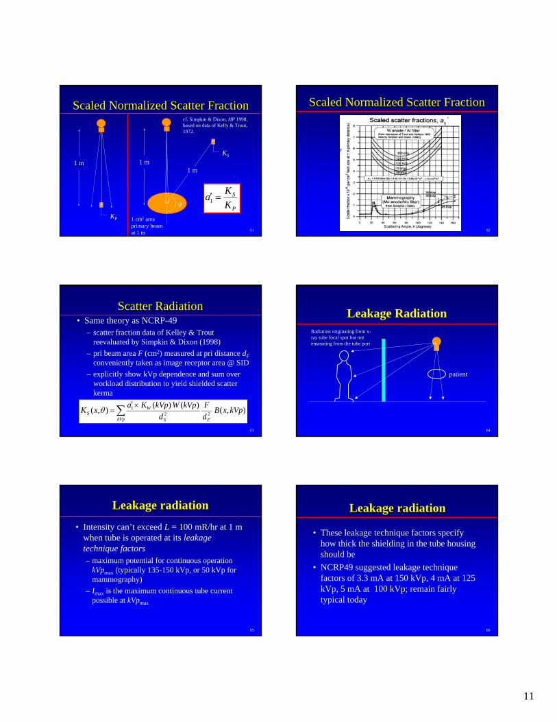
61
Scaled Normalized Scatter FractionScaled Normalized Scatter Fraction
KP
1 mKS
1 m1 m
1 cm2 area primary beam at 1 m
θ P
S
KKa =′1
cf. Simpkin & Dixon, HP 1998, based on data of Kelly & Trout, 1972.
62
'
Scaled Normalized Scatter FractionScaled Normalized Scatter Fraction
63
Scatter RadiationScatter Radiation• Same theory as NCRP-49
– scatter fraction data of Kelley & Trout reevaluated by Simpkin & Dixon (1998)
– pri beam area F (cm2) measured at pri distance dFconveniently taken as image receptor area @ SID
– explicitly show kVp dependence and sum over workload distribution to yield shielded scatter kerma
),()()(),( 221 kVpxB
dF
dkVpWkVpKaxK
FkVp S
WS ∑ ×′
=θ
64
Leakage Radiation
patient
Radiation originating from x-ray tube focal spot but not emanating from the tube port
65
Leakage radiationLeakage radiation
• Intensity can’t exceed L = 100 mR/hr at 1 m when tube is operated at its leakage technique factors– maximum potential for continuous operation
kVpmax (typically 135-150 kVp, or 50 kVp for mammography)
– Imax is the maximum continuous tube current possible at kVpmax
66
Leakage radiationLeakage radiation
• These leakage technique factors specify how thick the shielding in the tube housing should be
• NCRP49 suggested leakage technique factors of 3.3 mA at 150 kVp, 4 mA at 125 kVp, 5 mA at 100 kVp; remain fairly typical today
12
67
Leakage radiationLeakage radiation• NCRP-147 calculations (and shielding methods
2 and 3) use – 3.3 mA at 150 kVp– worst case leakage rates– (Subsequently, we’ve found that assuming 4 mA at
125 kVp leakage technique factors specifies barriers that are 10-20% thicker than in the report)
– However, typical leakage rates are 0-30% of the maximum leakage so we don’t see a problem
68
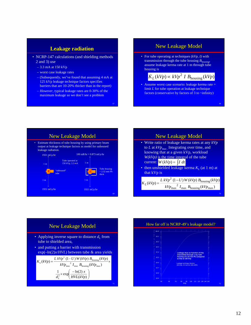
New Leakage ModelNew Leakage Model
• For tube operating at techniques (kVp, I) with transmission through the tube housing Bhousing, assume leakage kerma rate at 1 m through tube housing is
• Assume worst case scenario: leakage kerma rate = limit L for tube operation at leakage technique factors (conservative by factors of 3 to ~infinity)
)()( housing2 kVpBIkVpkVpKL ∝&
69
New Leakage ModelNew Leakage Model• Estimate thickness of tube housing by using primary beam
output at leakage technique factors as model for unhousedleakage radiation.
1 m
1 m
“unhoused”tube
1931 mGy/hr
1931 mGy/hr
1 m
1 mTube operated at 150 kVp, 3.3 mA
Tube housing = 2.32 mm Pbthick
1931 mGy/hr
100 mR/hr = 0.873 mGy/hr
70
New Leakage ModelNew Leakage Model• Write ratio of leakage kerma rates at any kVp
to L at kVpmax . Integrating over time, and knowing that at a given kVp, workload W(kVp) is the time integral of the tube current:
• then unshielded leakage kerma KL (at 1 m) at that kVp is
∫= dtIkVpW )(
)(
)()()1()(
maxhousingmax2
max
housing2
kVpBIkVp
kVpBkVpWUkVpLkVpKL
−=
71
New Leakage ModelNew Leakage Model
• Applying inverse square to distance dL from tube to shielded area,
• and putting a barrier with transmission exp(–ln(2)x/HVL) between tube & area yields
⎟⎟⎠
⎞⎜⎜⎝
⎛ −×
×−
=
)()2ln(exp1
)()()()1(
)(
2
maxhousingmax2
max
housing2
kVpHVLx
d
kVpBIkVpkVpBkVpWUkVpL
kVpK
L
L
7250 60 70 80 90 100 110 120 130 140 150
kVp
1E-9
1E-8
1E-7
1E-6
1E-5
1E-4
1E-3
1E-2
1E-1
1E+0
Leakage dose as function of kVp transmitted through x-ray tube housing of 2.32 mm Pb compared to that at 150 kVp
Leakage technique factors:150 kVp, 3.3 mA for 100 mR/hr
How far off is NCRPHow far off is NCRP--4949’’s leakage model?s leakage model?
13
73
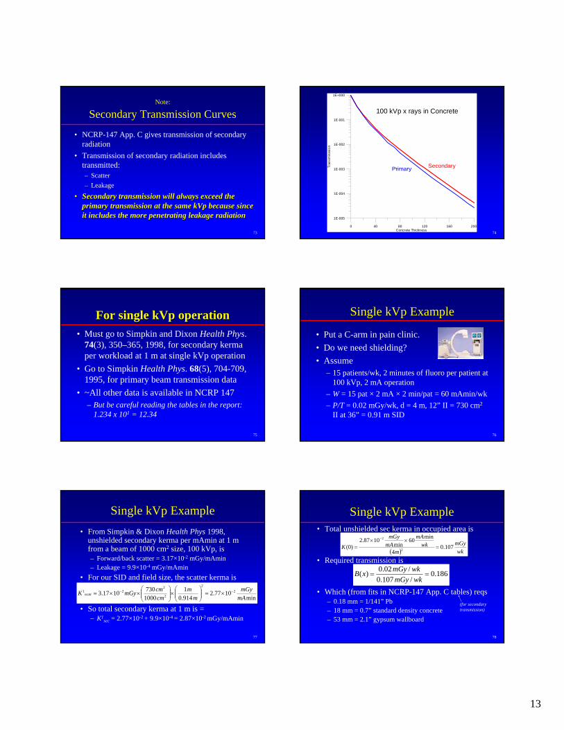
Note:
Secondary Transmission Curves
• NCRP-147 App. C gives transmission of secondary radiation
• Transmission of secondary radiation includes transmitted:– Scatter– Leakage
•• Secondary transmission will always exceed the Secondary transmission will always exceed the primary transmission at the same kVp because since primary transmission at the same kVp because since it includes the more penetrating leakage radiationit includes the more penetrating leakage radiation
740 40 80 120 160 200
Concrete Thickness
1E-005
1E-004
1E-003
1E-002
1E-001
1E+000
Tran
smis
ssio
n
SecondaryPrimary
100 kVp x rays in Concrete
75
For single kVp operationFor single kVp operation• Must go to Simpkin and Dixon Health Phys.
74(3), 350–365, 1998, for secondary kermaper workload at 1 m at single kVp operation
• Go to Simpkin Health Phys. 68(5), 704-709, 1995, for primary beam transmission data
• ~All other data is available in NCRP 147– But be careful reading the tables in the report:
1.234 x 101 = 12.34
76
Single kVp Example
• Put a C-arm in pain clinic. • Do we need shielding?• Assume
– 15 patients/wk, 2 minutes of fluoro per patient at 100 kVp, 2 mA operation
– W = 15 pat × 2 mA × 2 min/pat = 60 mAmin/wk– P/T = 0.02 mGy/wk, d = 4 m, 12” II = 730 cm2
II at 36” = 0.91 m SID
77
Single kVp Example• From Simpkin & Dixon Health Phys 1998,
unshielded secondary kerma per mAmin at 1 m from a beam of 1000 cm2 size, 100 kVp, is– Forward/back scatter = 3.17×10⁻² mGy/mAmin– Leakage = 9.9×10⁻⁴ mGy/mAmin
• For our SID and field size, the scatter kerma is
• So total secondary kerma at 1 m is = – K1
sec = 2.77×10⁻² + 9.9×10-4 = 2.87×10⁻² mGy/mAmin
min1077.2
914.01
10007301017.3 2
2
2
221
mAmGy
mm
cmcmmGyK scatt
−− ×=⎟⎟⎠
⎞⎜⎜⎝
⎛×⎟⎟⎠
⎞⎜⎜⎝
⎛××=
78
Single kVp Example• Total unshielded sec kerma in occupied area is
• Required transmission is
• Which (from fits in NCRP-147 App. C tables) reqs– 0.18 mm = 1/141” Pb– 18 mm = 0.7” standard density concrete– 53 mm = 2.1” gypsum wallboard
( ) wkmGy
mwk
mAmA
mGy
K 107.04
min60min
1087.2)0( 2
2
=××
=
−
186.0/107.0
/02.0)( ==wkmGy
wkmGyxB
(for secondary transmission)
14
79
Shielding Model No. 2Shielding Model No. 2• For each clinical workload distribution, of
total workload Wnorm per patient, for both primary and secondary barriers, NCRP 147 provides:– K1 , the kerma per patient at 1 m distance
• Primary kerma per patient KP1 is in Table 4.5
• Secondary kerma per patient Ksec1 is in Table 4.7
– B, the transmission of the radiation generated by this workload distribution for primary or secondary barriers (cf App B & C)
80
Shielding Model No. 2Shielding Model No. 2• The unshielded kerma, K(0), for
– N patient procedures (suggested values of N are in Table 4.3) or, equivalently
– total workload Wtot (where workload/pat = Wnorm)– can tweak Wtot by a QE-specified different
workload per patient, Wsite
• Kerma is then
– (where U is replaced by 1 for secondary barriers)norm
tot
WdWUK
dNUKK 2
1
2
1)0( ==
81
Shielding Model No. 2Shielding Model No. 2• Ratio of P/T to K(0) is the required transmission
– (again, U is replaced by 1 for secondary barriers)
•• Transmission Transmission BB is now a function of is now a function of –– barrier material and thicknessbarrier material and thickness–– workload distributionworkload distribution–– primary or secondaryprimary or secondary
1
2
1
2
)0(/)(
UDTWWdP
UDTNdP
KTPxB
tot
norm===
82
CathCath Lab Example: WallLab Example: Wall
• Assume d=4 m, uncontrolled area P = 0.02 mGy wk-1, T=1, 12” =30.5 cm diameter image receptor, 90° scatter, N=25 patients wk-1
• From Table 4.7, look up secondary kerma at 1 m per patient for Cath Lab distribution: Ksec
1 = 2.7 mGy patient-1
• Total unshielded weekly kerma is then1
2
11
22.4)4(
257.2)0( −−−
=×
= wkmGym
wkpatpatmGyK
83
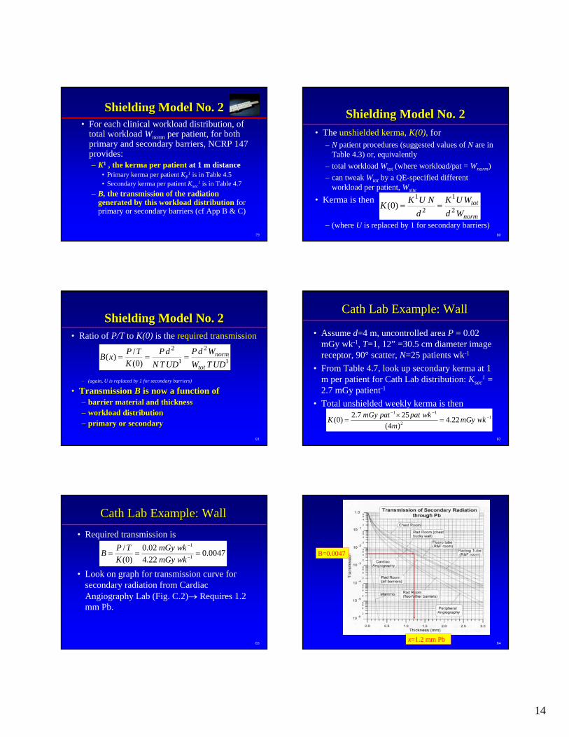
CathCath Lab Example: WallLab Example: Wall• Required transmission is
• Look on graph for transmission curve for secondary radiation from Cardiac Angiography Lab (Fig. C.2)→ Requires 1.2 mm Pb.
0047.022.402.0
)0(/
1
1
=== −
−
wkmGywkmGy
KTPB
84
B=0.0047
x=1.2 mm Pb
15
85
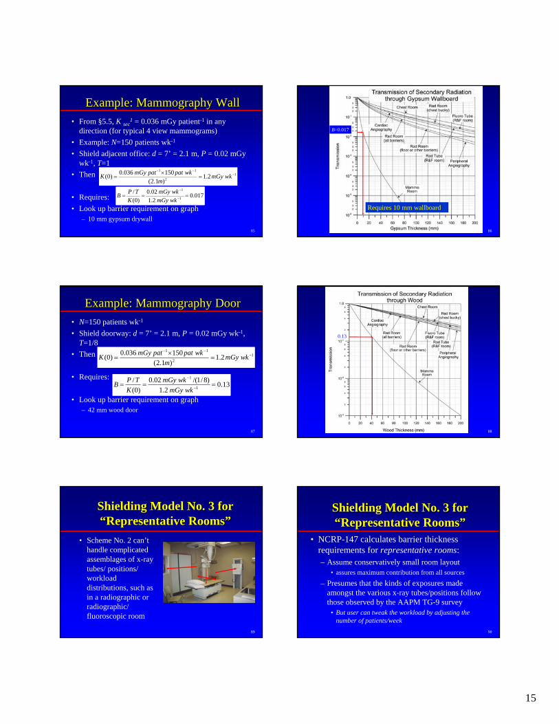
Example: Mammography WallExample: Mammography Wall• From §5.5, K sec
1 = 0.036 mGy patient-1 in any direction (for typical 4 view mammograms)
• Example: N=150 patients wk-1
• Shield adjacent office: d = 7’ = 2.1 m, P = 0.02 mGy wk-1, T=1
• Then
• Requires:• Look up barrier requirement on graph
– 10 mm gypsum drywall
12
11
2.1)1.2(150036.0)0( −
−−
=×
= wkmGym
wkpatpatmGyK
017.02.102.0
)0(/
1
1
=== −
−
wkmGywkmGy
KTPB
86
Requires 10 mm wallboard
B=0.017
87
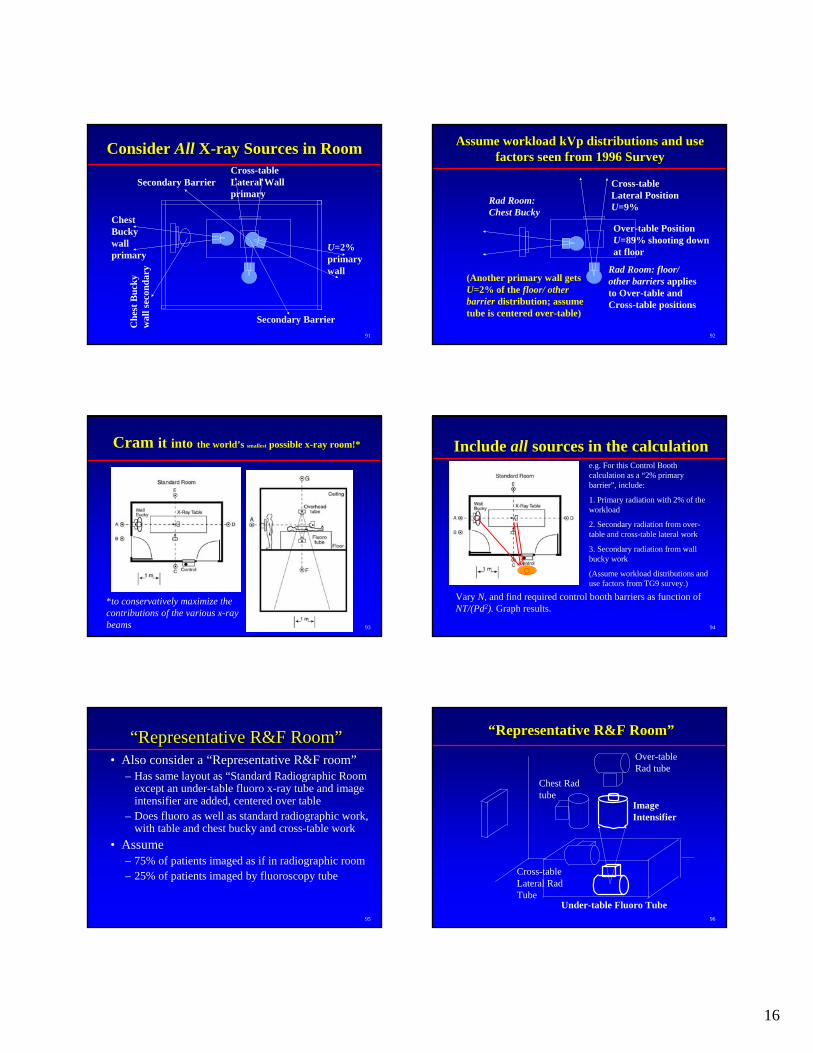
Example: Mammography DoorExample: Mammography Door• N=150 patients wk-1
• Shield doorway: d = 7’ = 2.1 m, P = 0.02 mGy wk-1, T=1/8
• Then
• Requires:
• Look up barrier requirement on graph– 42 mm wood door
12
11
2.1)1.2(150036.0)0( −
−−
=×
= wkmGym
wkpatpatmGyK
13.02.1
)8/1/(02.0)0(
/1
1
=== −
−
wkmGywkmGy
KTPB
88
0.13
89
Shielding Model No. 3 for Shielding Model No. 3 for ““Representative RoomsRepresentative Rooms””
• Scheme No. 2 can’t handle complicated assemblages of x-ray tubes/ positions/ workload distributions, such as in a radiographic or radiographic/ fluoroscopic room
90
Shielding Model No. 3 for Shielding Model No. 3 for ““Representative RoomsRepresentative Rooms””
• NCRP-147 calculates barrier thickness requirements for representative rooms:– Assume conservatively small room layout
• assures maximum contribution from all sources
– Presumes that the kinds of exposures made amongst the various x-ray tubes/positions follow those observed by the AAPM TG-9 survey
• But user can tweak the workload by adjusting the number of patients/week
16
91
Consider Consider AllAll XX--ray Sources in Roomray Sources in Room
Chest Buckywall primary
Cross-table Lateral Wall primary
Che
st B
ucky
wal
l sec
onda
ry
U=2% primary wall
Secondary Barrier
Secondary Barrier
92
Assume workload kVp distributions and use Assume workload kVp distributions and use factors seen from 1996 Surveyfactors seen from 1996 Survey
Rad Room:Chest Bucky
Rad Room: floor/ other barriers applies to Over-table and Cross-table positions
Cross-table Lateral Position U=9%
Over-table Position U=89% shooting down at floor
(Another primary wall gets U=2% of the floor/ other barrier distribution; assume tube is centered over-table)
93
Cram Cram itit intointo the worldthe world’’s s smallestsmallest possible xpossible x--ray room!*ray room!*
*to conservatively maximize the contributions of the various x-ray beams 94
Include Include allall sources in the calculationsources in the calculatione.g. For this Control Booth calculation as a “2% primary barrier”, include:
1. Primary radiation with 2% of the workload
2. Secondary radiation from over-table and cross-table lateral work
3. Secondary radiation from wall bucky work
(Assume workload distributions and use factors from TG9 survey.)
Vary N, and find required control booth barriers as function of NT/(Pd2). Graph results.
95
““Representative R&F RoomRepresentative R&F Room””• Also consider a “Representative R&F room”
– Has same layout as “Standard Radiographic Room except an under-table fluoro x-ray tube and image intensifier are added, centered over table
– Does fluoro as well as standard radiographic work, with table and chest bucky and cross-table work
• Assume– 75% of patients imaged as if in radiographic room– 25% of patients imaged by fluoroscopy tube
96
Chest Radtube
Cross-table Lateral RadTube
Over-table Rad tube
““Representative R&F RoomRepresentative R&F Room””
ImageIntensifier
Under-table Fluoro Tube
17
97
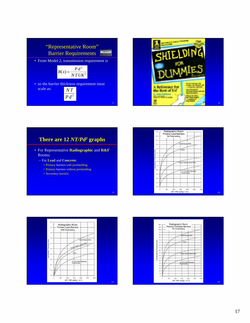
““Representative RoomRepresentative Room””Barrier RequirementsBarrier Requirements
• From Model 2, transmission requirement is
• so the barrier thickness requirement must scale as:
1
2
)(UKTNdPxB =
2dPTN
98
99
There are 12 There are 12 NT/PdNT/Pd22 graphsgraphs
• For Representative Radiographic and R&FRooms:– For Lead and Concrete:
• Primary barriers with preshielding• Primary barriers without preshielding• Secondary barriers
100
101 102
18
1030.1 1.0 10.0 100.0 1000.0
NT/Pd2(mSv-1m-2)
0.0
0.2
0.4
0.6
0.8
1.0
1.2
1.4
1.6
1.8
2.0
2.2Le
ad B
arrie
r Thi
ckne
ss R
equi
rem
ent (
mm
)
22.9 cm
30.5 cm35.6 cm
Cardiac AngiographyShielding Barrier Requirements
Lead
Image IntensifierDiameter:
TO BE READ BY PHYSICISTS ONLY
104
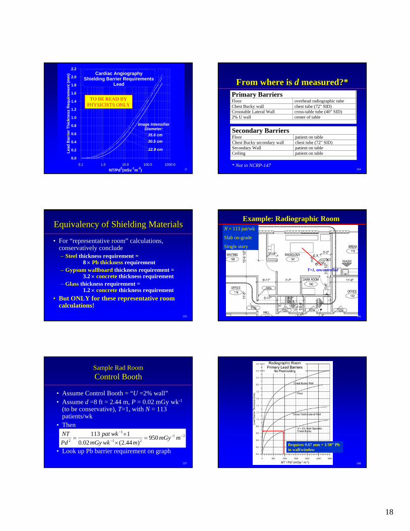
From where is From where is dd measured?*measured?*Primary Barriers Floor overhead radiographic tube Chest Bucky wall chest tube (72" SID) Crosstable Lateral Wall cross-table tube (40" SID) 2% U wall center of table
Secondary BarriersFloor patient on tableChest Bucky secondary wall chest tube (72" SID)Secondary Wall patient on tableCeiling patient on table
* Not in NCRP-147
105
Equivalency of Shielding MaterialsEquivalency of Shielding Materials
• For “representative room” calculations, conservatively conclude– Steel thickness requirement =
8 × Pb thickness requirement– Gypsum wallboard thickness requirement =
3.2 × concrete thickness requirement– Glass thickness requirement =
1.2 × concrete thickness requirement• But ONLY for these representative room
calculations!106
Example: Radiographic RoomExample: Radiographic RoomN = 113 pat/wk
Slab on-grade
Single story
T=1, uncontrolled
107
Sample Sample RadRad RoomRoomControl BoothControl Booth
• Assume Control Booth = “U =2% wall”• Assume d =8 ft = 2.44 m, P = 0.02 mGy wk-1
(to be conservative), T=1, with N = 113 patients/wk
• Then
• Look up Pb barrier requirement on graph
2121
1
2 950)44.2(02.0
1113 −−−
−
=×
×= mmGy
mwkmGywkpat
PdNT
108
Requires 0.67 mm = 1/38” Pbin wall/window
19
109
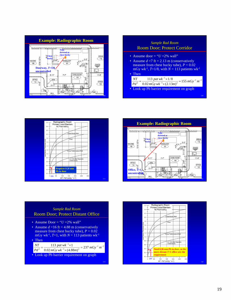
Example: Radiographic RoomExample: Radiographic Room
Doorway, T=1/8, uncontrolled
Chest bucky
Tube directed at chest bucky
110
Sample Sample RadRad RoomRoomRoomRoom Door; Protect CorridorDoor; Protect Corridor
• Assume door = “U =2% wall”• Assume d =7 ft = 2.13 m (conservatively
measure from chest bucky tube), P = 0.02 mGy wk-1, T=1/8, with N = 113 patients wk-1
• Then
• Look up Pb barrier requirement on graph
2121
1
2 155)31.2(02.0
8/1113 −−−
−
=××
= mmGymwkmGy
wkpatPdNT
111
Requires 0.28 mm Pb in door
155112
Example: Radiographic RoomExample: Radiographic Room
Office, T=1, uncontrolled
Chest bucky
Tube directed at chest bucky
113
Sample Sample RadRad RoomRoomRoomRoom Door; Protect Distant OfficeDoor; Protect Distant Office
• Assume Door = “U =2% wall”• Assume d =16 ft = 4.88 m (conservatively
measure from chest bucky tube), P = 0.02 mGy wk-1, T=1, with N = 113 patients wk-1
• Then
• Look up Pb barrier requirement on graph
2121
1
2 237)88.4(02.0
1113 −−−
−
=×
×= mmGy
mwkmGywkpat
PdNT
114
Need 0.36 mm Pb in door, so the more-distant T=1 office sets the requirement
237
20
115
0.11.0
10.0100.0
1000.0N
T/Pd 2(mSv -1m
-2)
0.0
0.2
0.4
0.6
0.8
1.0
1.2
1.4
1.6
1.8
2.0
2.2
Lead Barrier Thickness Requirement (mm)
22.9 cm30.5 cm35.6 cm
Cardiac A
ngiographyShielding B
arrier Requirem
entsLead
Image IntensifierD
iameter:
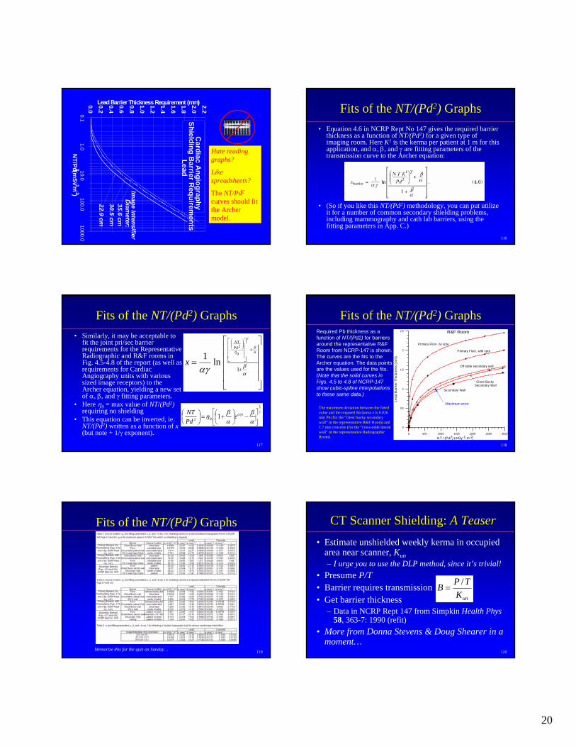
Hate reading graphs?
Like spreadsheets?
The NT/Pd2
curves should fit the Archer model.
116
Fits of the NT/(Pd2) Graphs• Equation 4.6 in NCRP Rept No 147 gives the required barrier
thickness as a function of NT/(Pd2) for a given type of imaging room. Here K1 is the kerma per patient at 1 m for this application, and α, β, and γ are fitting parameters of the transmission curve to the Archer equation:
• (So if you like this NT/(Pd2) methodology, you can put utilize it for a number of common secondary shielding problems, including mammography and cath lab barriers, using the fitting parameters in App. C.)
117
Fits of the NT/(Pd2) Graphs• Similarly, it may be acceptable to
fit the joint pri/sec barrier requirements for the Representative Radiographic and R&F rooms in Fig. 4.5-4.8 of the report (as well as requirements for Cardiac Angiography units with various sized image receptors) to the Archer equation, yielding a new set of α, β, and γ fitting parameters.
• Here η0 = max value of NT/(Pd2) requiring no shielding
• This equation can be inverted, ie. NT/(Pd2) written as a function of x (but note + 1/γ exponent).
⎥⎥⎥⎥
⎦
⎤
⎢⎢⎢⎢
⎣
⎡
=+
+⎥⎥⎥
⎦
⎤
⎢⎢⎢
⎣
⎡⎟⎟⎠
⎞⎜⎜⎝
⎛
αβ
αβ
γ
η
αγ 1
0
2
ln1PdNT
x
γαγ
αβ
αβη
1
02 1 ⎥⎦
⎤⎢⎣
⎡−⎟
⎠⎞
⎜⎝⎛ +=⎟
⎠⎞
⎜⎝⎛ xe
PdNT
118
Fits of the NT/(Pd2) Graphs
0 500 1000 1500 2000 2500 3000
NT / (Pd2) (mGy-1 m-2)
0
0.5
1
1.5
2
2.5
Lead
Bar
rier T
hick
ness
(mm
)
R&F Room
Chest Bucky Secondary Wall
Primary Floor, no xpre
Off-table secondary wall
Secondary Wall
Primary Floor, with xpre
Required Pb thickness as a function of NT/(Pd2) for barriers around the representative R&F Room from NCRP-147 is shown. The curves are the fits to the Archer equation. The data points are the values used for the fits. (Note that the solid curves in Figs. 4.5 to 4.8 of NCRP-147 show cubic-spline interpolations to these same data.)
Maximum errorThe maximum deviation between the fitted value and the required thickness x is 0.026 mm Pb (for the “chest bucky secondary wall” in the representative R&F Room) and 1.7 mm concrete (for the “cross-table lateral wall” in the representative Radiographic Room).
119
Fits of the NT/(Pd2) Graphs
Memorize this for the quiz on Sunday… 120
CT Scanner Shielding: CT Scanner Shielding: A TeaserA Teaser• Estimate unshielded weekly kerma in occupied
area near scanner, Kun– I urge you to use the DLP method, since it’s trivial!
• Presume P/T• Barrier requires transmission• Get barrier thickness
– Data in NCRP Rept 147 from Simpkin Health Phys 58, 363-7: 1990 (refit)
• More from Donna Stevens & Doug Shearer in a moment…
unKTPB /
=
21
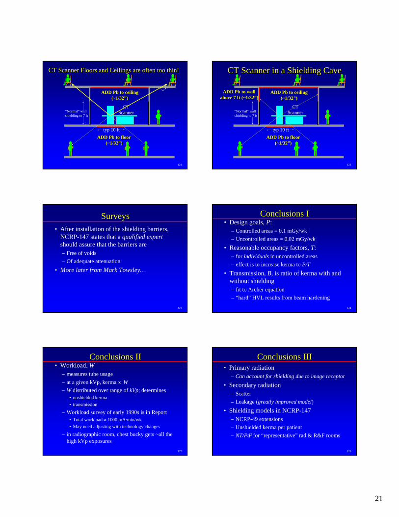
121
CT Scanner Floors and Ceilings are often too thin!CT Scanner Floors and Ceilings are often too thin!
“Normal” wall shielding to 7 ft
CT Scanner
ADD ADD PbPb to floor to floor (~1/32(~1/32””))
typ 10 ft
ADD ADD PbPb to ceiling to ceiling (~1/32(~1/32””))
122
CT Scanner in a Shielding CaveCT Scanner in a Shielding Cave
“Normal” wall shielding to 7 ft
CT Scanner
ADD ADD PbPb to floor to floor (~1/32(~1/32””))
typ 10 ft
ADD ADD PbPb to ceiling to ceiling (~1/32(~1/32””))
ADD ADD PbPb to wall to wall above 7 ft (~1/32above 7 ft (~1/32””))
123
SurveysSurveys• After installation of the shielding barriers,
NCRP-147 states that a qualified expertshould assure that the barriers are – Free of voids– Of adequate attenuation
• More later from Mark Towsley…
124
Conclusions IConclusions I• Design goals, P:
– Controlled areas = 0.1 mGy/wk– Uncontrolled areas = 0.02 mGy/wk
• Reasonable occupancy factors, T:– for individuals in uncontrolled areas– effect is to increase kerma to P/T
• Transmission, B, is ratio of kerma with and without shielding– fit to Archer equation– “hard” HVL results from beam hardening
125
Conclusions IIConclusions II• Workload, W
– measures tube usage– at a given kVp, kerma ∝ W– W distributed over range of kVp; determines
• unshielded kerma• transmission
– Workload survey of early 1990s is in Report• Total workload ≠ 1000 mA·min/wk• May need adjusting with technology changes
– in radiographic room, chest bucky gets ~all the high kVp exposures
126
Conclusions IIIConclusions III• Primary radiation
– Can account for shielding due to image receptor• Secondary radiation
– Scatter– Leakage (greatly improved model)
• Shielding models in NCRP-147– NCRP-49 extensions– Unshielded kerma per patient– NT/Pd2 for “representative” rad & R&F rooms
22
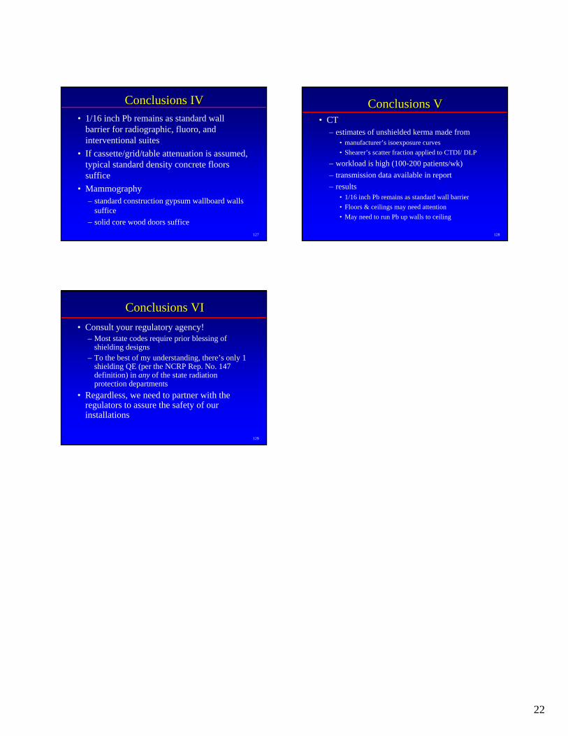
127
Conclusions IVConclusions IV• 1/16 inch Pb remains as standard wall
barrier for radiographic, fluoro, and interventional suites
• If cassette/grid/table attenuation is assumed, typical standard density concrete floors suffice
• Mammography– standard construction gypsum wallboard walls
suffice– solid core wood doors suffice
128
Conclusions VConclusions V• CT
– estimates of unshielded kerma made from• manufacturer’s isoexposure curves• Shearer’s scatter fraction applied to CTDI/ DLP
– workload is high (100-200 patients/wk)– transmission data available in report– results
• 1/16 inch Pb remains as standard wall barrier• Floors & ceilings may need attention• May need to run Pb up walls to ceiling
129
Conclusions VIConclusions VI• Consult your regulatory agency!
– Most state codes require prior blessing of shielding designs
– To the best of my understanding, there’s only 1 shielding QE (per the NCRP Rep. No. 147 definition) in any of the state radiation protection departments
• Regardless, we need to partner with the regulators to assure the safety of our installations