simotion d410-2 - ucc.colorado.eduucc.colorado.edu/siemens/d410-2_operating_en-us.pdfsimotion d410-2...
TRANSCRIPT
� SIMOTION D410- �2
___________________
___________________
___________________
___________________
___________________
___________________
___________________
___________________
___________________
SIMOTION
SIMOTION D410-2
Manual
Valid for SIMOTION D410-2 DP
02/2012
Preface
Description 1
Operator control (hardware) 2
Interfaces 3
Technical data 4
Dimension drawings 5
Spare parts / accessories 6
Standards and approvals A
ESD guidelines B
Siemens Automation
Legal information
Legal information Warning notice system
This manual contains notices you have to observe in order to ensure your personal safety, as well as to prevent damage to property. The notices referring to your personal safety are highlighted in the manual by a safety alert symbol, notices referring only to property damage have no safety alert symbol. These notices shown below are graded according to the degree of danger.
DANGER indicates that death or severe personal injury will result if proper precautions are not taken.
WARNING indicates that death or severe personal injury may result if proper precautions are not taken.
CAUTION with a safety alert symbol, indicates that minor personal injury can result if proper precautions are not taken.
CAUTION without a safety alert symbol, indicates that property damage can result if proper precautions are not taken.
NOTICE indicates that an unintended result or situation can occur if the relevant information is not taken into account.
If more than one degree of danger is present, the warning notice representing the highest degree of danger will be used. A notice warning of injury to persons with a safety alert symbol may also include a warning relating to property damage.
Qualified Personnel The product/system described in this documentation may be operated only by personnel qualified for the specific task in accordance with the relevant documentation, in particular its warning notices and safety instructions. Qualified personnel are those who, based on their training and experience, are capable of identifying risks and avoiding potential hazards when working with these products/systems.
Proper use of Siemens products Note the following:
WARNING Siemens products may only be used for the applications described in the catalog and in the relevant technical documentation. If products and components from other manufacturers are used, these must be recommended or approved by Siemens. Proper transport, storage, installation, assembly, commissioning, operation and maintenance are required to ensure that the products operate safely and without any problems. The permissible ambient conditions must be complied with. The information in the relevant documentation must be observed.
Trademarks All names identified by ® are registered trademarks of Siemens AG. The remaining trademarks in this publication may be trademarks whose use by third parties for their own purposes could violate the rights of the owner.
Disclaimer of Liability We have reviewed the contents of this publication to ensure consistency with the hardware and software described. Since variance cannot be precluded entirely, we cannot guarantee full consistency. However, the information in this publication is reviewed regularly and any necessary corrections are included in subsequent editions.
Siemens AG Industry Sector Postfach 48 48 90026 NÜRNBERG GERMANY
Copyright © Siemens AG 2012. All rights reserved
SIMOTION D410-2 Manual, 02/2012 3
Preface
Contents of the Product Manual This document is part of the SIMOTION D documentation package.
Scope The SIMOTION D410-2 Manual describes the SIMOTION D410-2 DP Control Unit.
Note
An independent SIMOTION D410 Manual is available for the SIMOTION D410 DP and SIMOTION D410 PN Control Units.
Standards The SIMOTION system was developed in accordance with ISO 9001 quality guidelines.
Sections in this manual The following information blocks describe of the purpose and the use of the manual:
● Description
This section provides information pertaining to the SIMOTION system and its integration in the information landscape.
● Operator control (hardware)
This section describes the operator control and display elements of the SIMOTION D410-2.
● Interfaces
This section provides information on the interfaces, their pin assignments and application options.
● Technical data
This section describes the properties and features of the SIMOTION D410-2.
● Dimension drawings
● Spare parts / accessories
This section provides information about accessories and spare parts for the SIMOTION D410-2.
Siemens Automation
Preface
SIMOTION D410-2 4 Manual, 02/2012
● Appendix
This section provides information about the various standards, approvals and EMC directives that the device complies with.
● Index to locate information
SIMOTION Documentation An overview of the SIMOTION documentation can be found in a separate list of references.
This documentation is included as electronic documentation in the scope of delivery of SIMOTION SCOUT. It comprises 10 documentation packages.
The following documentation packages are available for SIMOTION V4.3:
● SIMOTION Engineering System
● SIMOTION System and Function Descriptions
● SIMOTION Service and Diagnostics
● SIMOTION IT
● SIMOTION Programming
● SIMOTION Programming - References
● SIMOTION C
● SIMOTION P
● SIMOTION D
● SIMOTION Supplementary Documentation
Additional information Click the following link to find information on the the following topics:
● Ordering documentation/overview of documentation
● Additional links to download documents
● Using documentation online (find and search in manuals/information)
http://www.siemens.com/motioncontrol/docu
Please send any questions about the technical documentation (e.g. suggestions for improvement, corrections) to the following e-mail address: [email protected]
My Documentation Manager Click the following link for information on how to compile documentation individually on the basis of Siemens content and how to adapt this for the purpose of your own machine documentation:
http://www.siemens.com/mdm
Preface
SIMOTION D410-2 Manual, 02/2012 5
Training Click the following link for information on SITRAIN - Siemens training courses for automation products, systems and solutions:
http://www.siemens.com/sitrain
FAQs Frequently Asked Questions can be found in SIMOTION Utilities & Applications, which are included in the scope of delivery of SIMOTION SCOUT, and in the Service&Support pages in Product Support:
http://support.automation.siemens.com
Technical support Country-specific telephone numbers for technical support are provided on the Internet under Contact:
http://www.siemens.com/automation/service&support
Disposal and recycling SIMOTION D410-2 is an environmentally friendly product! It includes the following features:
● In spite of its excellent resistance to fire, the flame-resistant agent in the plastic used for the housing does not contain halogens.
● Identification of plastic materials in accordance with ISO 11469.
● Less material used because the unit is smaller and with fewer components thanks to integration in ASICs.
The disposal of the products described in this manual should be performed in compliance with the valid national regulations.
The products can be largely recycled owing to their low pollutant content. To recycle and dispose of your old device in an environmentally friendly way, please contact a recycling company certified for electronic waste.
If you have any further questions about disposal and recycling, please contact your local Siemens representative. Contact details can be found in our contacts database on the Internet at:
http://www.automation.siemens.com/partner
Siemens Automation
Preface
SIMOTION D410-2 6 Manual, 02/2012
Further information / FAQs You can find further information on this manual under the following FAQ:
http://support.automation.siemens.com/WW/view/de/27585482
The following information sources are also available:
● SIMOTION Utilities & Applications: SIMOTION Utilities & Applications will be included in the SIMOTION SCOUT scope of delivery and, along with FAQs, also contain free utilities (e.g. calculation tools, optimization tools, etc.) as well as application examples (ready-to-apply solutions such as winders, cross cutters or handling)
● The latest SIMOTION FAQs at http://support.automation.siemens.com/WW/view/en/10805436/133000
● SIMOTION SCOUT online help
● For additional documentation (separate document), please refer to the list of references
SIMOTION D410-2 Manual, 02/2012 7
Table of contents
Preface ...................................................................................................................................................... 3
1 Description................................................................................................................................................. 9
1.1 System overview............................................................................................................................9
1.2 System components ....................................................................................................................13
1.3 I/O integration...............................................................................................................................17
1.4 SIMOTION D410-2 DP representation ........................................................................................18
1.5 Type plates...................................................................................................................................19
1.6 CompactFlash card......................................................................................................................20
1.7 Licensing ......................................................................................................................................23
1.8 Safety information ........................................................................................................................24
2 Operator control (hardware)..................................................................................................................... 25
2.1 Overview of operator control and display elements.....................................................................25
2.2 Operator controls .........................................................................................................................26 2.2.1 Service selector switch ................................................................................................................26 2.2.2 Mode selector switch ...................................................................................................................27 2.2.3 DIAG button .................................................................................................................................29 2.2.4 RESET button ..............................................................................................................................30 2.2.5 Switch S5.0 ..................................................................................................................................30 2.2.6 SIMOTION CompactFlash card...................................................................................................31
2.3 Error and status displays .............................................................................................................32
3 Interfaces................................................................................................................................................. 33
3.1 Overview of interfaces .................................................................................................................33
3.2 DRIVE-CLiQ interface..................................................................................................................34
3.3 PROFIBUS DP interfaces ............................................................................................................36
3.4 Encoder interface (HTL/TTL/SSI) ................................................................................................38
3.5 Digital I/Os / temperature sensor / analog input ..........................................................................41 3.5.1 Properties.....................................................................................................................................41 3.5.2 Interface characteristics ...............................................................................................................42 3.5.3 Interface assignment....................................................................................................................42 3.5.4 Use of the interfaces ....................................................................................................................47 3.5.5 Connection examples ..................................................................................................................49
3.6 Power supply................................................................................................................................54
3.7 Ethernet interface.........................................................................................................................55
3.8 Measuring sockets .......................................................................................................................57
3.9 Power Module Interface ...............................................................................................................58
Siemens Automation
Table of contents
SIMOTION D410-2 8 Manual, 02/2012
4 Technical data ......................................................................................................................................... 59
4.1 Shipping and storage conditions................................................................................................. 59
4.2 Mechanical and climatic ambient conditions............................................................................... 60
4.3 System data, connection values, dimensions and weight .......................................................... 62
4.4 Interfaces and performance features .......................................................................................... 63 4.4.1 PLC and motion control performance ......................................................................................... 63 4.4.2 Communication ........................................................................................................................... 64 4.4.3 Onboard I/Os............................................................................................................................... 65 4.4.4 Onboard encoder interface ......................................................................................................... 67
4.5 Clock ........................................................................................................................................... 68
5 Dimension drawings ................................................................................................................................ 71
5.1 SIMOTION D410-2 DP dimension drawing ................................................................................ 71
5.2 Mounting plate dimension drawing ............................................................................................. 72
5.3 CAD data, dimension drawings, and circuit-diagram macros ..................................................... 73
6 Spare parts / accessories ........................................................................................................................ 75
6.1 Available spare parts and accessories ....................................................................................... 75
6.2 TM31 terminal module ................................................................................................................ 77
6.3 TM41 terminal module ................................................................................................................ 78
6.4 TM54F terminal module .............................................................................................................. 78
6.5 TM15 and TM17 High Feature terminal modules ....................................................................... 80
6.6 CUA31/CUA32 control unit adapter ............................................................................................ 81
6.7 DMC20/DME20 DRIVE-CLiQ hub .............................................................................................. 82
A Standards and approvals ......................................................................................................................... 83
A.1 General rules............................................................................................................................... 83
A.2 Device-specific information ......................................................................................................... 85
A.3 Safety of electronic controllers.................................................................................................... 85
B ESD guidelines ........................................................................................................................................ 87
B.1 ESD definition ............................................................................................................................. 87
B.2 Electrostatic charging of individuals............................................................................................ 88
B.3 Basic measures for protection against discharge of static electricity ......................................... 89
Index........................................................................................................................................................ 91
SIMOTION D410-2 Manual, 02/2012 9
Description 11.1 System overview
SIMOTION D SIMOTION D is a drive-based version of SIMOTION based on the SINAMICS S120 drive family.
With SIMOTION D, the SIMOTION PLC and motion control functionalities as well as the SINAMICS S120 drive software run on shared control hardware.
SIMOTION D is available in two versions:
● SIMOTION D410-2 is a compact control unit predestined for single-axis applications.
● SIMOTION D4x5-2 is a control unit for multi-axis applications in the SINAMICS S120 booksize format.
The following performance variants of the SIMOTION D4x5-2 control units are offered:
Control unit Performance variant Range of applications SIMOTION D425-2 BASIC performance For up to 16 axes SIMOTION D435-2 STANDARD performance For up to 32 axes SIMOTION D445-2 HIGH performance For up to 64 axes SIMOTION D455-2 ULTRA-HIGH performance For up to 128 axes or applications with very
short control cycles
Note
The SIMOTION D410-2 is described in this manual.
Separate manuals are available for the SIMOTION D4x5-2 and the SIMOTION D4x5 and SIMOTION D410 predecessor modules.
SIMOTION D is an integral part of the Totally Integrated Automation (TIA) concept. TIA is characterized by integrated data management, configuration, and communication for all products and systems. Thus, an extensive toolbox of automation modules is also available for the SIMOTION D410-2.
Siemens Automation
Description 1.1 System overview
SIMOTION D410-2 10 Manual, 02/2012
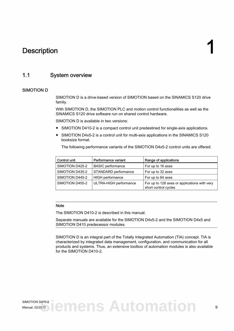
SIMOTION D410-2
Figure 1-1 SIMOTION D410-2
SIMOTION D410-2 is a compact control unit for single-axis applications.
The control unit is snapped directly on to the SINAMICS S120 PM340 power module in blocksize format and has an integrated drive control for either one servo, one vector or one V/f axis.
SIMOTION D410-2 can be extended with additional SINAMICS S110/S120 control units (e.g. CU305) and so can also be used for smaller multi-axis applications (e.g. with 2 - 3 axes).
Description 1.1 System overview
SIMOTION D410-2 Manual, 02/2012 11
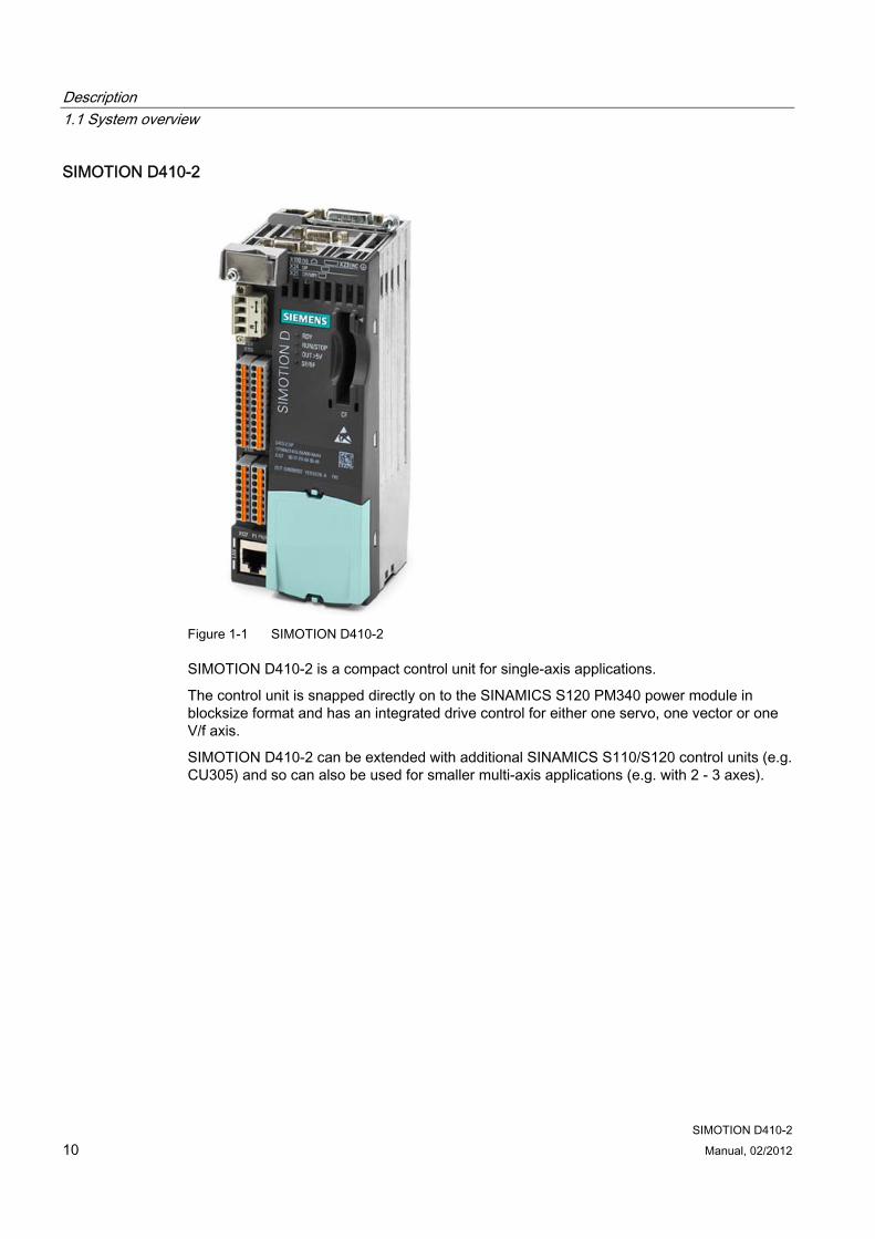
Example of a single-axis application
Figure 1-2 Application example with one axis
The example shows a single-axis application, consisting of a SIMOTION D410-2 (control unit) ① that is snapped directly on to the SINAMICS PM340 power module ②. The motor is supplied with power via the PM340. The encoder is connected by means of DRIVE-CLiQ.
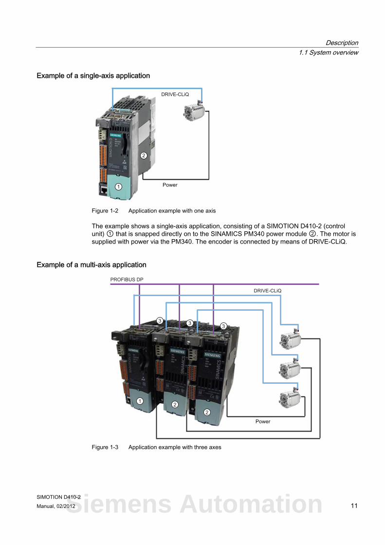
Example of a multi-axis application
Figure 1-3 Application example with three axes
Siemens Automation
Description 1.1 System overview
SIMOTION D410-2 12 Manual, 02/2012
The example shows an application with three axes, consisting of:
● One SIMOTION D410-2 DP (control unit) ①, snapped on to the PM340 ③
The SIMOTION D410-2 DP is snapped directly on to the SINAMICS PM340 power module. The motor is supplied with power via the PM340. The encoder is connected by means of DRIVE-CLiQ.
● Two SINAMICS S110 CU305 ②, snapped on to the PM340 ③
The control units are connected to the SIMOTION D410-2 DP via PROFIBUS DP. The two SINAMICS S110 CU305 are snapped directly on to the SINAMICS PM340 power modules. The motors are supplied with power via the PM340. The encoders are connected by means of DRIVE-CLiQ.
Note
Path interpolation is not supported for V4.3.
Application Combining a power module with SIMOTION D410-2 forms a compact single drive for machine and plant engineering.
Applications include:
● Machine concepts with central drive (e.g. presses, printing and packaging machines, etc.)
● Modular machine concepts where the machine modules broken down to single axes
● Single drives with high accuracy, stability and concentricity requirements (compared with standard drives) in machine and industrial plant engineering
● Single drives for transport tasks (conveying, raising, lowering)
● Single drives with integrated PLC functionality and expanded motion control functionality such as output cams or cams
● Drives without power recovery (wire drawing, extruding)
● Drive connections with high availability requirements (incoming supply failure may not cause all axes to fail)
● Small multi-axis groupings (typically two to three axes) based on SINAMICS S110/120 blocksize.
Hardware components As central hardware the SIMOTION D410-2 control unit is made up of the SIMOTION runtime system and the SINAMICS drive control.
A range of additional SINAMICS S120 components, such as SMx encoder systems or terminal modules can be connected via DRIVE-CLiQ.
With a few exceptions (e.g. no BOP20 basic operator panel, etc.), the drive control integrated in SIMOTION D410-2 has the same control properties and performance features as the SINAMICS S120 CU310-2 control unit.
Description 1.2 System components
SIMOTION D410-2 Manual, 02/2012 13
Extension of the drive computing performance To fully utilize the motion control performance of a SIMOTION D410-2 when required, the drive-side computing performance can be extended by connecting additional SINAMICS S110/S120 control units (e.g. CU305, CU310-2, etc.) via PROFIBUS to the SIMOTION D410-2.
Software components The basic functionality of SIMOTION D is supplied on a CompactFlash Card containing the following:
● The SIMOTION runtime system with the following functions:
– Freely programmable runtime system (IEC 61131)
– Various runtime levels (tasks)
– PLC and arithmetic functionality
– Motion control functions
– Communication functions
● The SINAMICS S120 drive control with the following functions:
– Current and torque control
– Speed control
1.2 System components
Overview SIMOTION D410-2 communicates with the components of the automation landscape via the following interfaces:
● PROFIBUS DP
● Ethernet
● DRIVE-CLiQ (DRIVE Component Link with IQ)
● Power module interface (PM-IF)
SIMOTION D features a SINAMICS Integrated drive element. Communication with the SINAMICS Integrated is via PROFIBUS mechanisms (DP Integrated), via PROFIdrive message frames.
Shorter cycle times and greater numbers of addresses for each node are achieved with the "DP Integrated" compared to the "external PROFIBUS DP".
The most important components of the system and their functions are shown below.
Siemens Automation
Description 1.2 System components
SIMOTION D410-2 14 Manual, 02/2012
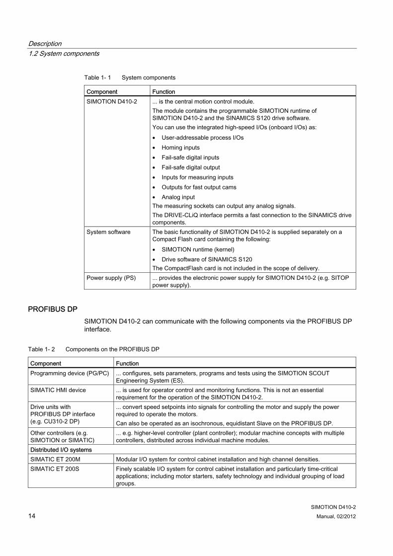
Table 1- 1 System components
Component Function SIMOTION D410-2 ... is the central motion control module.
The module contains the programmable SIMOTION runtime of SIMOTION D410-2 and the SINAMICS S120 drive software. You can use the integrated high-speed I/Os (onboard I/Os) as: • User-addressable process I/Os • Homing inputs • Fail-safe digital inputs • Fail-safe digital output • Inputs for measuring inputs • Outputs for fast output cams • Analog input The measuring sockets can output any analog signals. The DRIVE-CLiQ interface permits a fast connection to the SINAMICS drive components.
System software The basic functionality of SIMOTION D410-2 is supplied separately on a Compact Flash card containing the following: • SIMOTION runtime (kernel) • Drive software of SINAMICS S120 The CompactFlash card is not included in the scope of delivery.
Power supply (PS) ... provides the electronic power supply for SIMOTION D410-2 (e.g. SITOP power supply).
PROFIBUS DP SIMOTION D410-2 can communicate with the following components via the PROFIBUS DP interface.
Table 1- 2 Components on the PROFIBUS DP
Component Function Programming device (PG/PC) ... configures, sets parameters, programs and tests using the SIMOTION SCOUT
Engineering System (ES). SIMATIC HMI device ... is used for operator control and monitoring functions. This is not an essential
requirement for the operation of the SIMOTION D410-2. Drive units with PROFIBUS DP interface (e.g. CU310-2 DP)
... convert speed setpoints into signals for controlling the motor and supply the power required to operate the motors. Can also be operated as an isochronous, equidistant Slave on the PROFIBUS DP.
Other controllers (e.g. SIMOTION or SIMATIC)
... e.g. higher-level controller (plant controller); modular machine concepts with multiple controllers, distributed across individual machine modules.
Distributed I/O systems SIMATIC ET 200M Modular I/O system for control cabinet installation and high channel densities. SIMATIC ET 200S Finely scalable I/O system for control cabinet installation and particularly time-critical
applications; including motor starters, safety technology and individual grouping of load groups.
Description 1.2 System components
SIMOTION D410-2 Manual, 02/2012 15
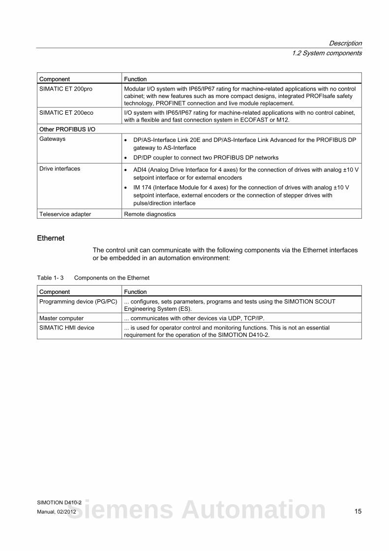
Component Function SIMATIC ET 200pro Modular I/O system with IP65/IP67 rating for machine-related applications with no control
cabinet; with new features such as more compact designs, integrated PROFIsafe safety technology, PROFINET connection and live module replacement.
SIMATIC ET 200eco I/O system with IP65/IP67 rating for machine-related applications with no control cabinet, with a flexible and fast connection system in ECOFAST or M12.
Other PROFIBUS I/O Gateways • DP/AS-Interface Link 20E and DP/AS-Interface Link Advanced for the PROFIBUS DP
gateway to AS-Interface • DP/DP coupler to connect two PROFIBUS DP networks
Drive interfaces • ADI4 (Analog Drive Interface for 4 axes) for the connection of drives with analog ±10 V setpoint interface or for external encoders
• IM 174 (Interface Module for 4 axes) for the connection of drives with analog ±10 V setpoint interface, external encoders or the connection of stepper drives with pulse/direction interface
Teleservice adapter Remote diagnostics
Ethernet The control unit can communicate with the following components via the Ethernet interfaces or be embedded in an automation environment:
Table 1- 3 Components on the Ethernet
Component Function Programming device (PG/PC) ... configures, sets parameters, programs and tests using the SIMOTION SCOUT
Engineering System (ES). Master computer ... communicates with other devices via UDP, TCP/IP. SIMATIC HMI device ... is used for operator control and monitoring functions. This is not an essential
requirement for the operation of the SIMOTION D410-2.
Siemens Automation
Description 1.2 System components
SIMOTION D410-2 16 Manual, 02/2012
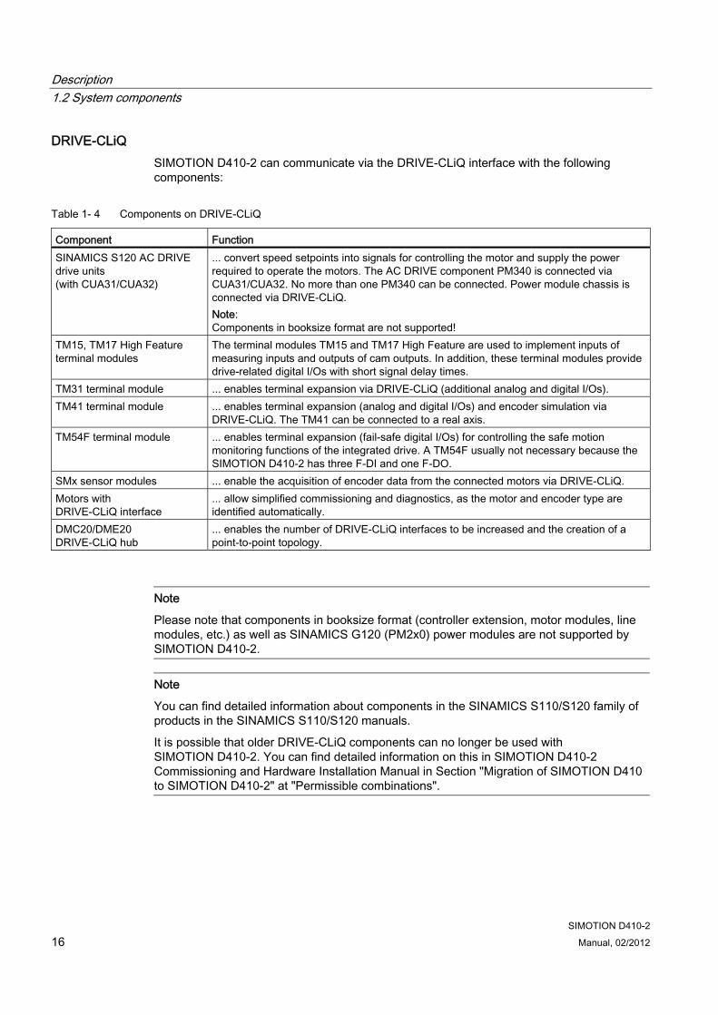
DRIVE-CLiQ SIMOTION D410-2 can communicate via the DRIVE-CLiQ interface with the following components:
Table 1- 4 Components on DRIVE-CLiQ
Component Function SINAMICS S120 AC DRIVE drive units (with CUA31/CUA32)
... convert speed setpoints into signals for controlling the motor and supply the power required to operate the motors. The AC DRIVE component PM340 is connected via CUA31/CUA32. No more than one PM340 can be connected. Power module chassis is connected via DRIVE-CLiQ. Note: Components in booksize format are not supported!
TM15, TM17 High Feature terminal modules
The terminal modules TM15 and TM17 High Feature are used to implement inputs of measuring inputs and outputs of cam outputs. In addition, these terminal modules provide drive-related digital I/Os with short signal delay times.
TM31 terminal module ... enables terminal expansion via DRIVE-CLiQ (additional analog and digital I/Os). TM41 terminal module ... enables terminal expansion (analog and digital I/Os) and encoder simulation via
DRIVE-CLiQ. The TM41 can be connected to a real axis. TM54F terminal module ... enables terminal expansion (fail-safe digital I/Os) for controlling the safe motion
monitoring functions of the integrated drive. A TM54F usually not necessary because the SIMOTION D410-2 has three F-DI and one F-DO.
SMx sensor modules ... enable the acquisition of encoder data from the connected motors via DRIVE-CLiQ. Motors with DRIVE-CLiQ interface
... allow simplified commissioning and diagnostics, as the motor and encoder type are identified automatically.
DMC20/DME20 DRIVE-CLiQ hub
... enables the number of DRIVE-CLiQ interfaces to be increased and the creation of a point-to-point topology.
Note
Please note that components in booksize format (controller extension, motor modules, line modules, etc.) as well as SINAMICS G120 (PM2x0) power modules are not supported by SIMOTION D410-2.
Note
You can find detailed information about components in the SINAMICS S110/S120 family of products in the SINAMICS S110/S120 manuals.
It is possible that older DRIVE-CLiQ components can no longer be used with SIMOTION D410-2. You can find detailed information on this in SIMOTION D410-2 Commissioning and Hardware Installation Manual in Section "Migration of SIMOTION D410 to SIMOTION D410-2" at "Permissible combinations".
Description 1.3 I/O integration
SIMOTION D410-2 Manual, 02/2012 17
1.3 I/O integration
Note
Note that not all modules in the ET 200 I/O family are approved for SIMOTION. Moreover, system-related functional differences can come into play when these I/Os or I/O systems are used on SIMOTION vs. on SIMATIC. For example, special process-control functions (e.g. HART modules, etc.) are not supported by SIMOTION for the ET 200M distributed I/O system.
A detailed, regularly updated list of the I/O modules approved for use with SIMOTION, as well as notes on their use, can be found at Internet address (http://support.automation.siemens.com/WW/view/en/11886029)
In addition to the I/O modules released for SIMOTION, in principle all certified standard PROFIBUS slaves (DP-V0/DP-V1/DP-V2) may be connected to SIMOTION D410-2. These modules are integrated via the GSD file (PROFIBUS) of the device's manufacturer.
Note
Please note that in isolated cases, additional boundary conditions must be fulfilled in order to integrate a module into SIMOTION. Thus, a few modules require "driver blocks" , e.g. in the form of function blocks, that permit (or simplify) integration.
For modules enabled for SIMOTION (e.g. SIMATIC S7-300 module FM 350-1, etc.), these driver modules are part of the SIMOTION SCOUT engineering system command library.
Siemens Automation
Description 1.4 SIMOTION D410-2 DP representation
SIMOTION D410-2 18 Manual, 02/2012
1.4 SIMOTION D410-2 DP representation
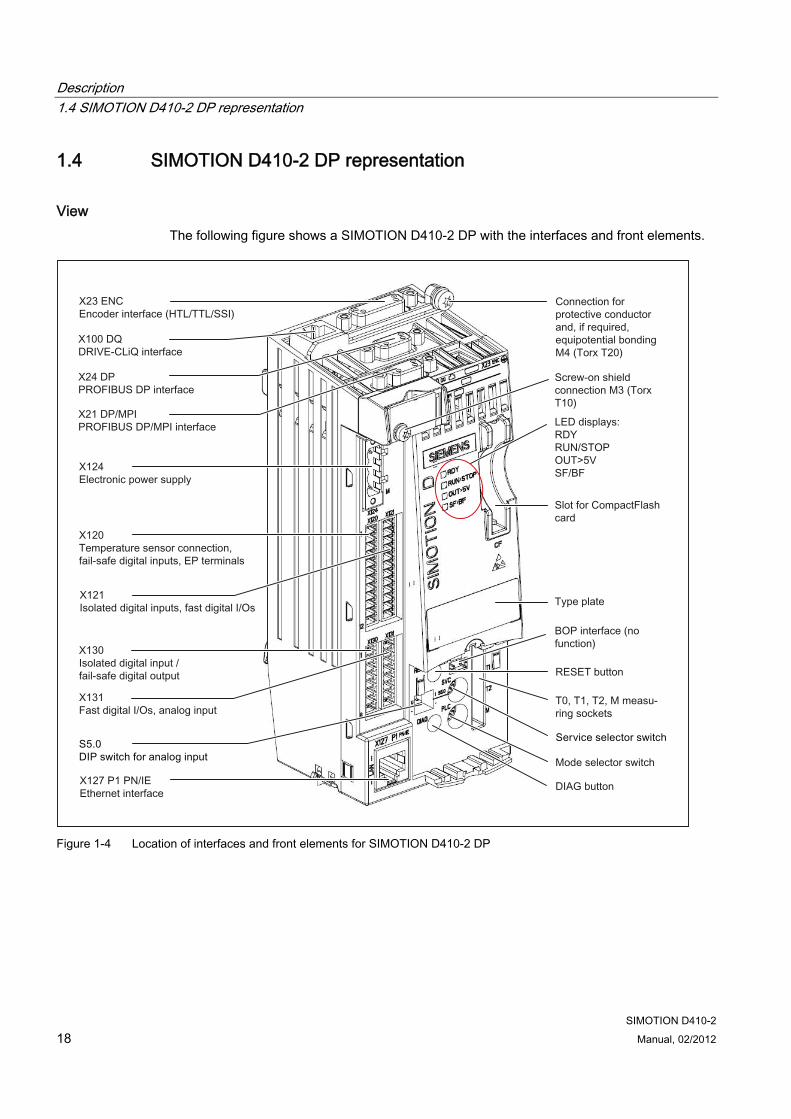
View The following figure shows a SIMOTION D410-2 DP with the interfaces and front elements.
Figure 1-4 Location of interfaces and front elements for SIMOTION D410-2 DP
Description 1.5 Type plates
SIMOTION D410-2 Manual, 02/2012 19
The interface to the power module (PM) is located at the rear of the SIMOTION D410-2.
Figure 1-5 Power Module Interface (PM-IF)
See also Interfaces (Page 33)
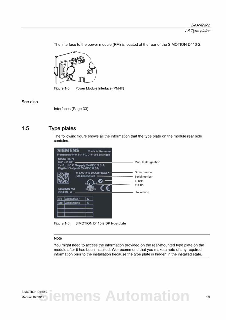
1.5 Type plates The following figure shows all the information that the type plate on the module rear side contains.
Module designation
Order number
Serial number
HW version
C-Tick
CULUS
Figure 1-6 SIMOTION D410-2 DP type plate
Note
You might need to access the information provided on the rear-mounted type plate on the module after it has been installed. We recommend that you make a note of any required information prior to the installation because the type plate is hidden in the installed state.
Siemens Automation
Description 1.6 CompactFlash card
SIMOTION D410-2 20 Manual, 02/2012
Note
The information contained in each field of the type plate on your actual control unit may differ from that presented in this manual (for example, a later product version, approvals and marks that have not yet been earned, etc., may be shown).
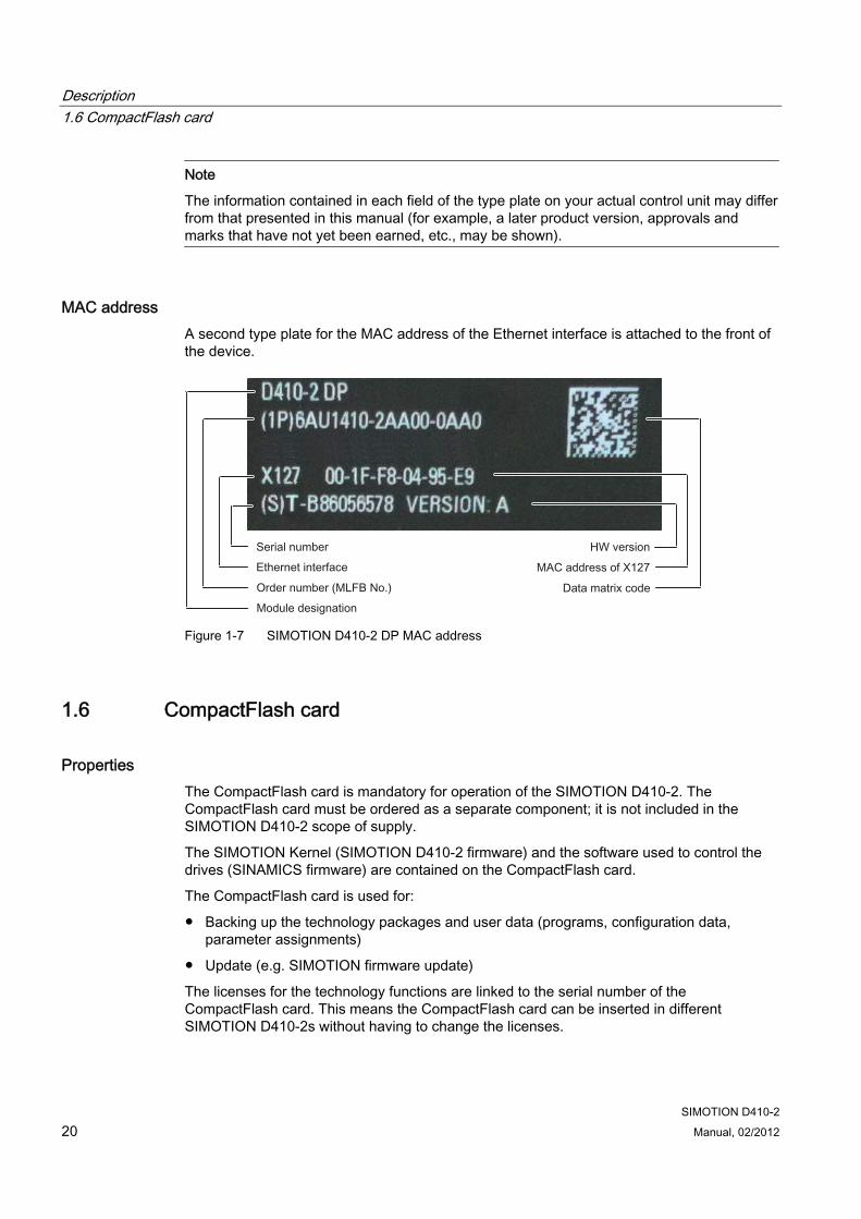
MAC address A second type plate for the MAC address of the Ethernet interface is attached to the front of the device.
Figure 1-7 SIMOTION D410-2 DP MAC address
1.6 CompactFlash card
Properties The CompactFlash card is mandatory for operation of the SIMOTION D410-2. The CompactFlash card must be ordered as a separate component; it is not included in the SIMOTION D410-2 scope of supply.
The SIMOTION Kernel (SIMOTION D410-2 firmware) and the software used to control the drives (SINAMICS firmware) are contained on the CompactFlash card.
The CompactFlash card is used for:
● Backing up the technology packages and user data (programs, configuration data, parameter assignments)
● Update (e.g. SIMOTION firmware update)
The licenses for the technology functions are linked to the serial number of the CompactFlash card. This means the CompactFlash card can be inserted in different SIMOTION D410-2s without having to change the licenses.
Description 1.6 CompactFlash card
SIMOTION D410-2 Manual, 02/2012 21
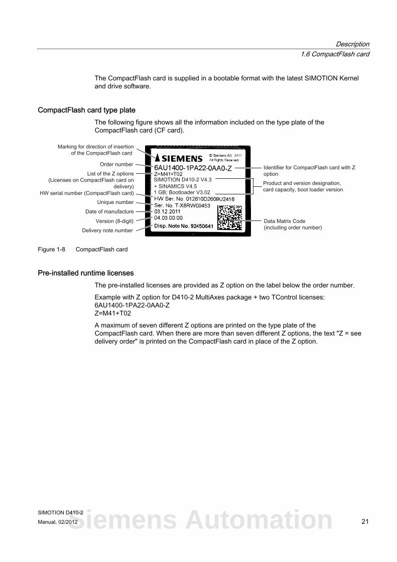
The CompactFlash card is supplied in a bootable format with the latest SIMOTION Kernel and drive software.
CompactFlash card type plate The following figure shows all the information included on the type plate of the CompactFlash card (CF card).
Figure 1-8 CompactFlash card
Pre-installed runtime licenses The pre-installed licenses are provided as Z option on the label below the order number.
Example with Z option for D410-2 MultiAxes package + two TControl licenses: 6AU1400-1PA22-0AA0-Z Z=M41+T02
A maximum of seven different Z options are printed on the type plate of the CompactFlash card. When there are more than seven different Z options, the text "Z = see delivery order" is printed on the CompactFlash card in place of the Z option.
Siemens Automation
Description 1.6 CompactFlash card
SIMOTION D410-2 22 Manual, 02/2012
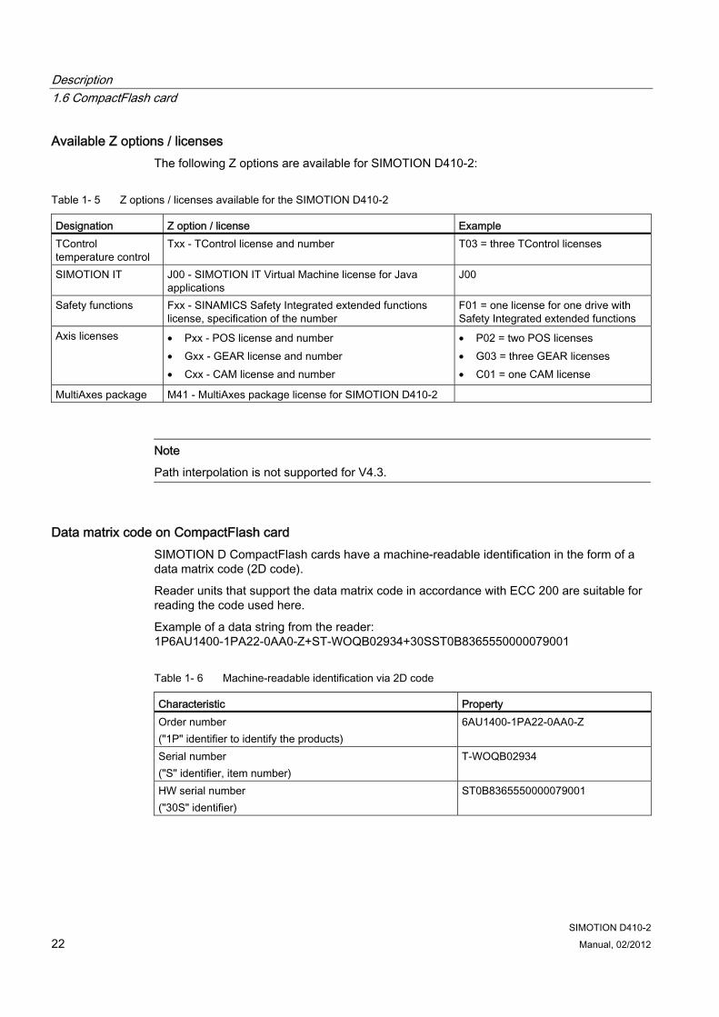
Available Z options / licenses The following Z options are available for SIMOTION D410-2:
Table 1- 5 Z options / licenses available for the SIMOTION D410-2
Designation Z option / license Example TControl temperature control
Txx - TControl license and number T03 = three TControl licenses
SIMOTION IT J00 - SIMOTION IT Virtual Machine license for Java applications
J00
Safety functions Fxx - SINAMICS Safety Integrated extended functions license, specification of the number
F01 = one license for one drive with Safety Integrated extended functions
Axis licenses • Pxx - POS license and number • Gxx - GEAR license and number • Cxx - CAM license and number
• P02 = two POS licenses • G03 = three GEAR licenses • C01 = one CAM license
MultiAxes package M41 - MultiAxes package license for SIMOTION D410-2
Note
Path interpolation is not supported for V4.3.
Data matrix code on CompactFlash card SIMOTION D CompactFlash cards have a machine-readable identification in the form of a data matrix code (2D code).
Reader units that support the data matrix code in accordance with ECC 200 are suitable for reading the code used here.
Example of a data string from the reader: 1P6AU1400-1PA22-0AA0-Z+ST-WOQB02934+30SST0B8365550000079001
Table 1- 6 Machine-readable identification via 2D code
Characteristic Property Order number ("1P" identifier to identify the products)
6AU1400-1PA22-0AA0-Z
Serial number ("S" identifier, item number)
T-WOQB02934
HW serial number ("30S" identifier)
ST0B8365550000079001
Description 1.7 Licensing
SIMOTION D410-2 Manual, 02/2012 23
In addition to the "serial number", CompactFlash cards also have a "HW serial number".
If licenses are purchased for licensed functions, a "license key" is generated from the HW serial number of the CompactFlash card and the serial number of the purchased licenses; such licenses are valid only for the associated CompactFlash card.
The data required for the licensing can be read by reader unit via the bar codes on the license certificates (Certificate of License "CoL") and the 2D code on the CompactFlash card in order, for example, to automate the licensing process.
1.7 Licensing
SIMOTION D410-2 licensing SIMOTION D410-2 is a compact control unit predestined for single-axis applications. SIMOTION D410-2 has an integrated drive control for either a servo, a vector or a V/f axis. One real axis can be used without requiring a license for a SIMOTION D410-2. Speed-controlled axes and virtual axes never require a license.
SIMOTION D410-2 can be extended with additional SINAMICS S110/S120 control units (e.g. CU305) and so can also be used for smaller multi-axis applications (e.g. with 2 - 3 axes). These additional axes must be licensed with the single-axis licenses or the "D410-2 MultiAxes Package". See chapter CompactFlash card (Page 20).
Note
If you use more than one real axis with SIMOTION D410-2, you must license these additional axes. The axis license with the highest functionality is covered by the inclusive license (a real axis). The functionality has the following granularity: CAM > GEAR > POS.
Example:
You use two real axes: 1 POS, 1 CAM. Because the CAM license has a higher value, and so inclusive, you only need to purchase a POS license.
Licenses are required for runtime functions such as SIMOTION IT Virtual Machine. These licenses can be pre-installed on a CompactFlash card (CF card) or ordered separately.
Additional references For more information about license management, see the SIMOTION SCOUT Configuration Manual. General information about licensing can be found in the SIMOTION motion control, SINAMICS S120 and motors for production machines catalog, PM21 catalog.
Siemens Automation
Description 1.8 Safety information
SIMOTION D410-2 24 Manual, 02/2012
1.8 Safety information Observe the following safety information when working with SIMOTION D410-2 and its components!
CAUTION The CompactFlash card may only be unplugged and plugged in when SIMOTION D410-2 is switched off (zero current)!
The SIMOTION D410-2 is in a de-energized state when all the LEDs are OFF.
The CompactFlash card is an ESD-sensitive component. When removing and inserting the CompactFlash card, observe the ESD regulations.
CAUTION The 50 mm clearances above and below the components must be observed. The ventilation openings at the top and bottom must not be covered by any connecting cables.
WARNING Safe, problem-free operation of the SIMOTION D control unit assumes proper transportation, storage, setup, and installation, as well as careful operation and maintenance.
In addition to the danger and warning information provided in the technical customer documentation, the applicable national, local, and plant-specific regulations and requirements must be taken into account.
Only safety extra-low voltage in accordance with EN/IEC 60950-1 may be connected to all connections and terminals.
SIMOTION D410-2 Manual, 02/2012 25
Operator control (hardware) 22.1 Overview of operator control and display elements
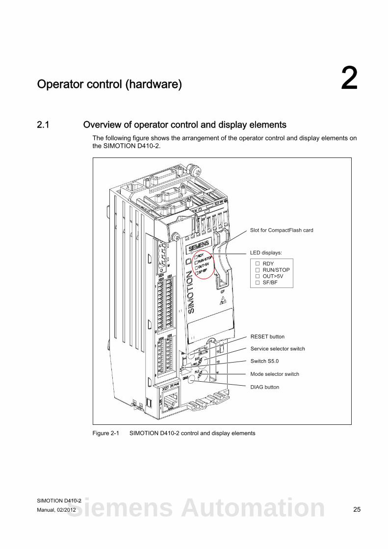
The following figure shows the arrangement of the operator control and display elements on the SIMOTION D410-2.
Figure 2-1 SIMOTION D410-2 control and display elements
Siemens Automation
Operator control (hardware) 2.2 Operator controls
SIMOTION D410-2 26 Manual, 02/2012
2.2 Operator controls
2.2.1 Service selector switch
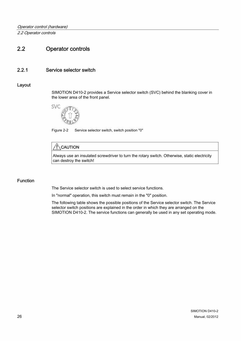
Layout SIMOTION D410-2 provides a Service selector switch (SVC) behind the blanking cover in the lower area of the front panel.
Figure 2-2 Service selector switch, switch position "0"
CAUTION Always use an insulated screwdriver to turn the rotary switch. Otherwise, static electricity can destroy the switch!
Function The Service selector switch is used to select service functions.
In "normal" operation, this switch must remain in the "0" position.
The following table shows the possible positions of the Service selector switch. The Service selector switch positions are explained in the order in which they are arranged on the SIMOTION D410-2. The service functions can generally be used in any set operating mode.
Operator control (hardware) 2.2 Operator controls
SIMOTION D410-2 Manual, 02/2012 27
Table 2- 1 Switch positions of the Service selector switch
Position Service mode Meaning 0 No service/diagnostic function activated 1 Delete/restore non-
volatile SIMOTION data
The non-volatile SIMOTION data of the SIMOTION D410-2 is first deleted and then restored with the contents of the PMEMORY backup file.
B Downgrade (device update tool)
SIMOTION D410-2 control units and projects can be upgraded using upgrade data created previously. This upgrade data is generated with the device update tool ("Project > Start device update tool" menu in SIMOTION SCOUT). If the upgrade process fails to bring about the desired result, the upgrade can be rejected by means of the switch position. This will roll the system back to the previous configuration.
D Backup of diagnostic data and non-volatile SIMOTION data
The diagnostic data and non-volatile SIMOTION data can be backed up in STOP, STOPU, and RUN state. The advantage of backing up in RUN state is the availability of enhanced diagnostic information (via websites) and TO alarm information.
Note
Alternatively, diagnostic data and non-volatile SIMOTION data can also be backed up via the DIAG button, see Section DIAG button (Page 29).
2.2.2 Mode selector switch
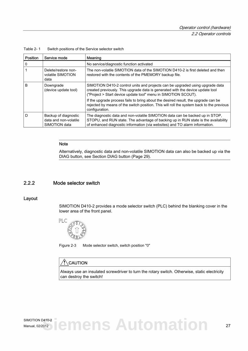
Layout SIMOTION D410-2 provides a mode selector switch (PLC) behind the blanking cover in the lower area of the front panel.
Figure 2-3 Mode selector switch, switch position "0"
CAUTION Always use an insulated screwdriver to turn the rotary switch. Otherwise, static electricity can destroy the switch!
Siemens Automation
Operator control (hardware) 2.2 Operator controls
SIMOTION D410-2 28 Manual, 02/2012
Function The following table contains the possible mode selector switch positions and the associated operating mode.
Table 2- 2 Mode selector switch positions
Position Operating mode
Meaning
0 RUN SIMOTION D410-2 executes the user program and the associated system services: • Read process image of inputs. • Execution of the user programs assigned to the execution system. • Write process image of outputs. The technology packages are active in this state. They can execute commands from the user program.
1 STOPU SIMOTION D410-2 does not execute any user program. • The technology packages are active. Test and commissioning functions can be executed.
The user program is not active. • The I/O modules are in a secure state, i.e. the digital outputs have the status "LOW" and the
analog outputs are at zero current/voltage.
2 STOP SIMOTION D410-2 does not execute any user program. • It is possible to load a complete user program. • All system services (communications, etc.) are active. • The I/O modules are in a secure state, i.e. the digital outputs have the status "LOW" and the
analog outputs are at zero current/voltage. • The technology packages are inactive, i.e. all enables are deleted. No axis motions can be
executed.
3 MRES Module memory reset / reset the SIMOTION D410-2 to the default settings. Using the MRES switch position, you can perform depending on the operating sequence • Overall reset of the SIMOTION D410-2 or • Restore the SIMOTION D410-2 to the default settings. For additional details on the operating sequence, refer to the SIMOTION D410-2 Commissioning and Hardware Installation Manual.
Note
In the "RUN" setting, you can also control the SIMOTION D410-2 operating mode from the SIMOTION SCOUT engineering system. This means that it is not necessary to adjust the mode selector switch to change the operating mode.
Operator control (hardware) 2.2 Operator controls
SIMOTION D410-2 Manual, 02/2012 29
Additional references Detailed information
● For information on setting the operating modes, refer to the SIMOTION SCOUT Configuration Manual.
● For device upgrade (device update tool), see Upgrading SIMOTION Devices Operating Instructions.
2.2.3 DIAG button
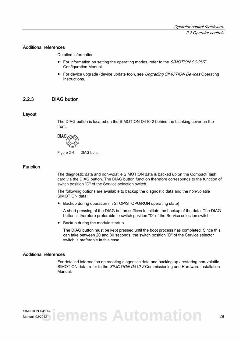
Layout The DIAG button is located on the SIMOTION D410-2 behind the blanking cover on the front.
Figure 2-4 DIAG button
Function The diagnostic data and non-volatile SIMOTION data is backed up on the CompactFlash card via the DIAG button. The DIAG button function therefore corresponds to the function of switch position "D" of the Service selection switch.
The following options are available to backup the diagnostic data and the non-volatile SIMOTION data:
● Backup during operation (in STOP/STOPU/RUN operating state)
A short pressing of the DIAG button suffices to initiate the backup of the data. The DIAG button is therefore preferable to switch position "D" of the Service selection switch.
● Backup during the module startup
The DIAG button must be kept pressed until the boot process has completed. Since this can take between 20 and 30 seconds, the switch position "D" of the Service selector switch is preferable in this case.
Additional references For detailed information on creating diagnostic data and backing up / restoring non-volatile SIMOTION data, refer to the SIMOTION D410-2 Commissioning and Hardware Installation Manual.
Siemens Automation
Operator control (hardware) 2.2 Operator controls
SIMOTION D410-2 30 Manual, 02/2012
2.2.4 RESET button
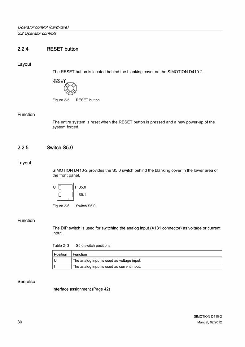
Layout The RESET button is located behind the blanking cover on the SIMOTION D410-2.
Figure 2-5 RESET button
Function The entire system is reset when the RESET button is pressed and a new power-up of the system forced.
2.2.5 Switch S5.0
Layout SIMOTION D410-2 provides the S5.0 switch behind the blanking cover in the lower area of the front panel.
Figure 2-6 Switch S5.0
Function The DIP switch is used for switching the analog input (X131 connector) as voltage or current input.
Table 2- 3 S5.0 switch positions
Position Function U The analog input is used as voltage input. I The analog input is used as current input.
See also Interface assignment (Page 42)
Operator control (hardware) 2.2 Operator controls
SIMOTION D410-2 Manual, 02/2012 31
2.2.6 SIMOTION CompactFlash card
Function The SIMOTION Kernel (SIMOTION D410-2 firmware) and the software used to control the drives (SINAMICS firmware) are contained on the CompactFlash card.
The CompactFlash card (CF card) is used to
● Backup technology packages and user data
● Update (e.g. SIMOTION firmware update)
Slot for CompactFlash card The CompactFlash card is inserted into the plug-in module over the blanking cover (see Overview of operator control and display elements (Page 25)).
Note
The CompactFlash card may only be inserted or removed while the module is in a de-energized state. The SIMOTION D410-2 is in a de-energized state when all the LEDs are OFF.
The CompactFlash card of the SIMOTION D410-2 must not be used in a SIMOTION D410, D4x5 or D4x5-2!
Additional information For more information on writing and formatting the CompactFlash card, refer to the SIMOTION D410-2 Commissioning Manual.
Siemens Automation
Operator control (hardware) 2.3 Error and status displays
SIMOTION D410-2 32 Manual, 02/2012
2.3 Error and status displays
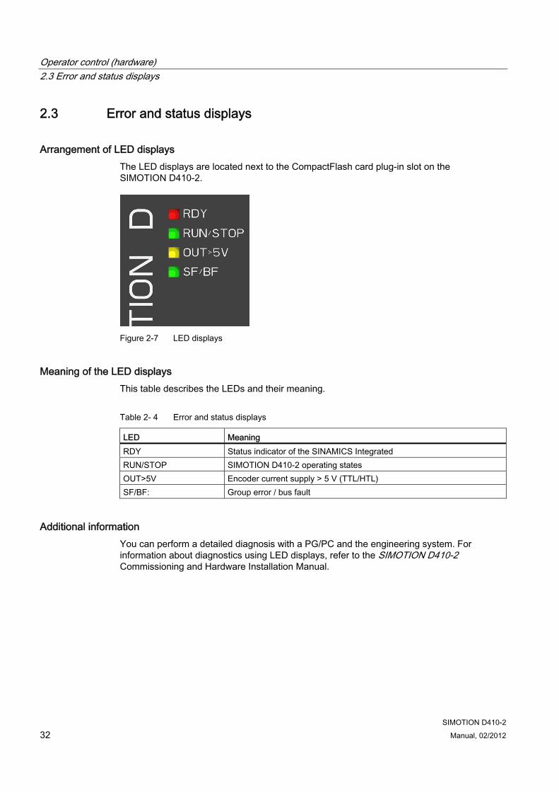
Arrangement of LED displays The LED displays are located next to the CompactFlash card plug-in slot on the SIMOTION D410-2.
Figure 2-7 LED displays
Meaning of the LED displays This table describes the LEDs and their meaning.
Table 2- 4 Error and status displays
LED Meaning RDY Status indicator of the SINAMICS Integrated RUN/STOP SIMOTION D410-2 operating states OUT>5V Encoder current supply > 5 V (TTL/HTL) SF/BF: Group error / bus fault
Additional information You can perform a detailed diagnosis with a PG/PC and the engineering system. For information about diagnostics using LED displays, refer to the SIMOTION D410-2 Commissioning and Hardware Installation Manual.
SIMOTION D410-2 Manual, 02/2012 33
Interfaces 33.1 Overview of interfaces
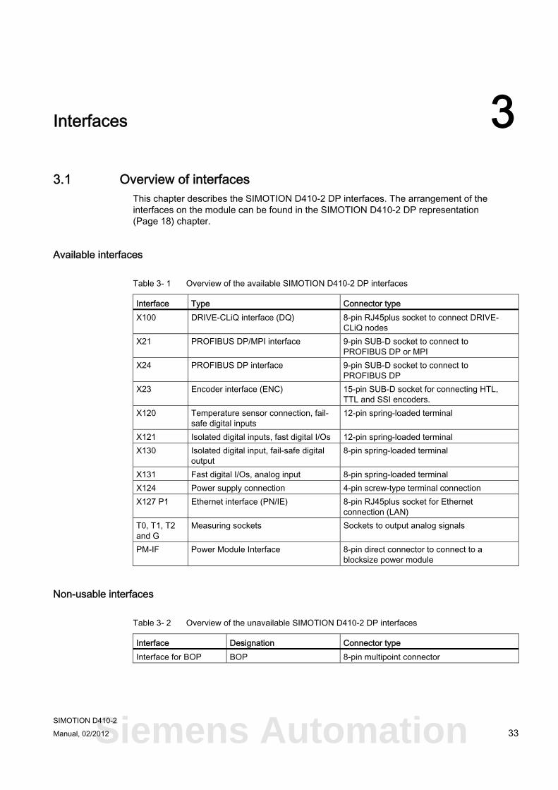
This chapter describes the SIMOTION D410-2 DP interfaces. The arrangement of the interfaces on the module can be found in the SIMOTION D410-2 DP representation (Page 18) chapter.
Available interfaces
Table 3- 1 Overview of the available SIMOTION D410-2 DP interfaces
Interface Type Connector type X100 DRIVE-CLiQ interface (DQ) 8-pin RJ45plus socket to connect DRIVE-
CLiQ nodes X21 PROFIBUS DP/MPI interface 9-pin SUB-D socket to connect to
PROFIBUS DP or MPI X24 PROFIBUS DP interface 9-pin SUB-D socket to connect to
PROFIBUS DP X23 Encoder interface (ENC) 15-pin SUB-D socket for connecting HTL,
TTL and SSI encoders. X120 Temperature sensor connection, fail-
safe digital inputs 12-pin spring-loaded terminal
X121 Isolated digital inputs, fast digital I/Os 12-pin spring-loaded terminal X130 Isolated digital input, fail-safe digital
output 8-pin spring-loaded terminal
X131 Fast digital I/Os, analog input 8-pin spring-loaded terminal X124 Power supply connection 4-pin screw-type terminal connection X127 P1 Ethernet interface (PN/IE) 8-pin RJ45plus socket for Ethernet
connection (LAN) T0, T1, T2 and G
Measuring sockets Sockets to output analog signals
PM-IF Power Module Interface 8-pin direct connector to connect to a blocksize power module
Non-usable interfaces
Table 3- 2 Overview of the unavailable SIMOTION D410-2 DP interfaces
Interface Designation Connector type Interface for BOP BOP 8-pin multipoint connector
Siemens Automation
Interfaces 3.2 DRIVE-CLiQ interface
SIMOTION D410-2 34 Manual, 02/2012
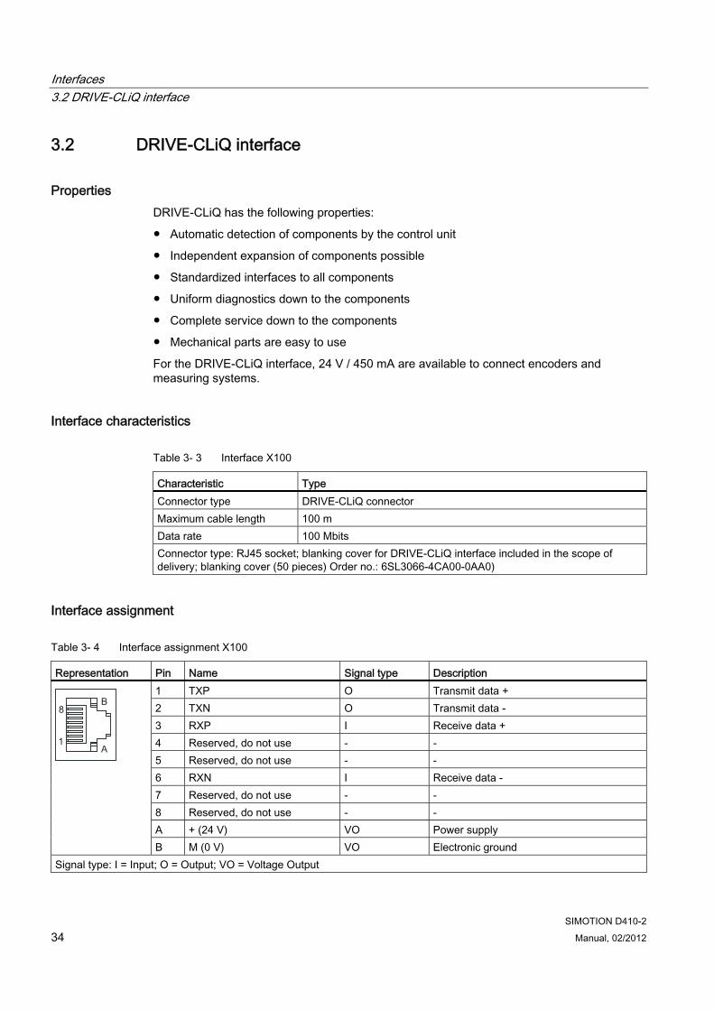
3.2 DRIVE-CLiQ interface
Properties DRIVE-CLiQ has the following properties:
● Automatic detection of components by the control unit
● Independent expansion of components possible
● Standardized interfaces to all components
● Uniform diagnostics down to the components
● Complete service down to the components
● Mechanical parts are easy to use
For the DRIVE-CLiQ interface, 24 V / 450 mA are available to connect encoders and measuring systems.
Interface characteristics
Table 3- 3 Interface X100
Characteristic Type Connector type DRIVE-CLiQ connector Maximum cable length 100 m Data rate 100 Mbits Connector type: RJ45 socket; blanking cover for DRIVE-CLiQ interface included in the scope of delivery; blanking cover (50 pieces) Order no.: 6SL3066-4CA00-0AA0)
Interface assignment
Table 3- 4 Interface assignment X100
Representation Pin Name Signal type Description 1 TXP O Transmit data + 2 TXN O Transmit data - 3 RXP I Receive data + 4 Reserved, do not use - - 5 Reserved, do not use - - 6 RXN I Receive data - 7 Reserved, do not use - - 8 Reserved, do not use - - A + (24 V) VO Power supply
B M (0 V) VO Electronic ground Signal type: I = Input; O = Output; VO = Voltage Output
Interfaces 3.2 DRIVE-CLiQ interface
SIMOTION D410-2 Manual, 02/2012 35
Connectable devices The following table contains the components that can communicate with SIMOTION D410-2 via the DRIVE-CLiQ interface. Note the max. number of nodes that can be connected to the DRIVE-CLiQ!
Note
Note also the topology rules of the SINAMICS S120, see SINAMICS S120 Function Manual, Section "Rules for wiring with DRIVE-CLiQ".
Table 3- 5 DRIVE-CLiQ connection topology
Component Max. number of connectable nodes Drive Max. one drive from the following:
• PM340 Blocksize Power Module (D410-2 directly snapped on) • PM340 Blocksize Power Module (D410-2 issued via CUA31/CUA32) • Power Module Chassis AC/AC
Motors with DRIVE-CLiQ interface, DRIVE-CLiQ encoder and SMx sensor modules
Max. five encoder systems via DRIVE-CLiQ: • Sensor modules (SMx) for transferring an encoder signal to DRIVE-CLiQ • Encoders with a DRIVE-CLiQ interface • Motors with DRIVE-CLiQ interface You require a DRIVE-CLiQ hub module (DMC20/DME20) or a CUA32 to connect more than one encoder system via DRIVE-CLiQ.
Terminal expansion modules Max. eight terminal modules (TM), of which • Maximum three TM15, TM17 High Feature, TM41 • Maximum eight TM15 DI/DO, TM31 • Maximum one TM54F
DRIVE-CLiQ hub module 20 (DMC20/DME20)
Max. one DMC20 or DME20 Note: Because an SMx sensor module and a motor with a DRIVE-CLiQ interface have only one DRIVE-CLiQ interface, a DMC20/DME20 must be used with a second encoder on the DRIVE-CLiQ. If a CUA31/CUA32 is used, the DMC20/DME20 is not required. Alternatively, a second encoder can also be connected via the X23 encoder interface.
Siemens Automation
Interfaces 3.3 PROFIBUS DP interfaces
SIMOTION D410-2 36 Manual, 02/2012
Additional information For information on the components that can be connected via DRIVE-CLiQ (setup, connection, configuration, etc.) see
● SINAMICS S120 Control Units and Additional System Components Manual
● SINAMICS S120 for AC Drives Manual
● SINAMICS S120 Commissioning Manual
● SINAMICS S120 Safety Integrated Function Manual
● TM15/TM17 High Feature SIMOTION Terminal Modules Commissioning Manual
● SIMOTION Terminal Modules TM15 / TM17 Manual
3.3 PROFIBUS DP interfaces
Properties SIMOTION D410-2 DP provides two interfaces for connection on the PROFIBUS DP:
● PROFIBUS DP/MPI interface (X21)
● PROFIBUS DP interface (X24)
The interfaces can be run asynchronously or isochronously, equidistant.
SIMOTION D410-2 DP includes master and I-slave functionality.
Interface characteristics
Table 3- 6 X21 and X24 interfaces
Characteristics Type Connector type 9-pin sub-D socket Cable type PROFIBUS cable Max. cable length 100 m at 12 Mbit/s Maximum data rate 12 Mbit/s
Interfaces 3.3 PROFIBUS DP interfaces
SIMOTION D410-2 Manual, 02/2012 37
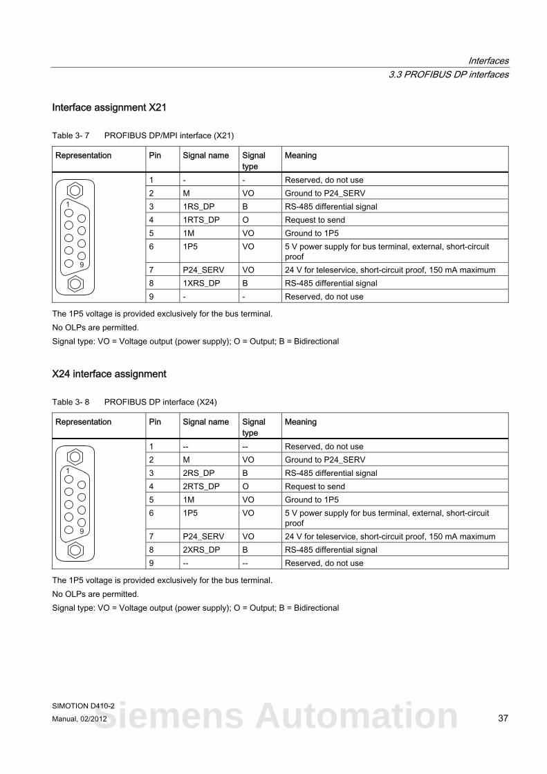
Interface assignment X21
Table 3- 7 PROFIBUS DP/MPI interface (X21)
Representation Pin Signal name Signal type
Meaning
1 - - Reserved, do not use 2 M VO Ground to P24_SERV 3 1RS_DP B RS-485 differential signal 4 1RTS_DP O Request to send 5 1M VO Ground to 1P5 6 1P5 VO 5 V power supply for bus terminal, external, short-circuit
proof 7 P24_SERV VO 24 V for teleservice, short-circuit proof, 150 mA maximum 8 1XRS_DP B RS-485 differential signal
9 - - Reserved, do not use
The 1P5 voltage is provided exclusively for the bus terminal. No OLPs are permitted. Signal type: VO = Voltage output (power supply); O = Output; B = Bidirectional
X24 interface assignment
Table 3- 8 PROFIBUS DP interface (X24)
Representation Pin Signal name Signal type
Meaning
1 -- -- Reserved, do not use 2 M VO Ground to P24_SERV 3 2RS_DP B RS-485 differential signal 4 2RTS_DP O Request to send 5 1M VO Ground to 1P5 6 1P5 VO 5 V power supply for bus terminal, external, short-circuit
proof 7 P24_SERV VO 24 V for teleservice, short-circuit proof, 150 mA maximum 8 2XRS_DP B RS-485 differential signal
9 -- -- Reserved, do not use
The 1P5 voltage is provided exclusively for the bus terminal. No OLPs are permitted. Signal type: VO = Voltage output (power supply); O = Output; B = Bidirectional
Siemens Automation
Interfaces 3.4 Encoder interface (HTL/TTL/SSI)
SIMOTION D410-2 38 Manual, 02/2012
Connectable devices The following devices can be connected to the PROFIBUS DP interfaces:
● PG/PC
● SIMATIC HMI devices
● SIMATIC controllers with PROFIBUS DP interface
● Distributed I/O
● Teleservice adapter
● Drive units with PROFIBUS DP interface (standard slaves)
Note
For remote diagnosis, a teleservice adapter can be connected to the PROFIBUS X21 or X24 interface. A teleservice adapter can only be connected to one of the two interfaces.
The power supply for the teleservice adapter (terminals 2 and 7) can accept current loads as high as 150 mA and is sustained short-circuit proof.
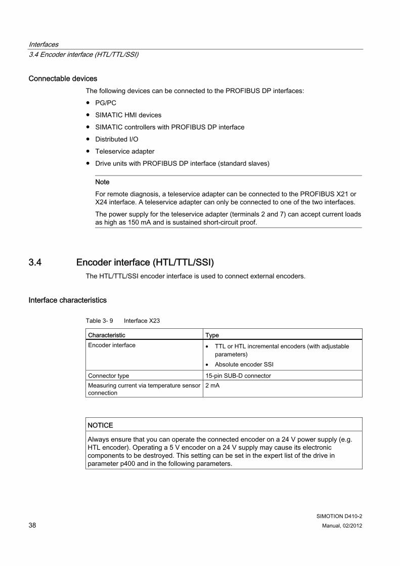
3.4 Encoder interface (HTL/TTL/SSI) The HTL/TTL/SSI encoder interface is used to connect external encoders.
Interface characteristics
Table 3- 9 Interface X23
Characteristic Type Encoder interface • TTL or HTL incremental encoders (with adjustable
parameters) • Absolute encoder SSI
Connector type 15-pin SUB-D connector Measuring current via temperature sensor connection
2 mA
NOTICE Always ensure that you can operate the connected encoder on a 24 V power supply (e.g. HTL encoder). Operating a 5 V encoder on a 24 V supply may cause its electronic components to be destroyed. This setting can be set in the expert list of the drive in parameter p400 and in the following parameters.
Interfaces 3.4 Encoder interface (HTL/TTL/SSI)
SIMOTION D410-2 Manual, 02/2012 39
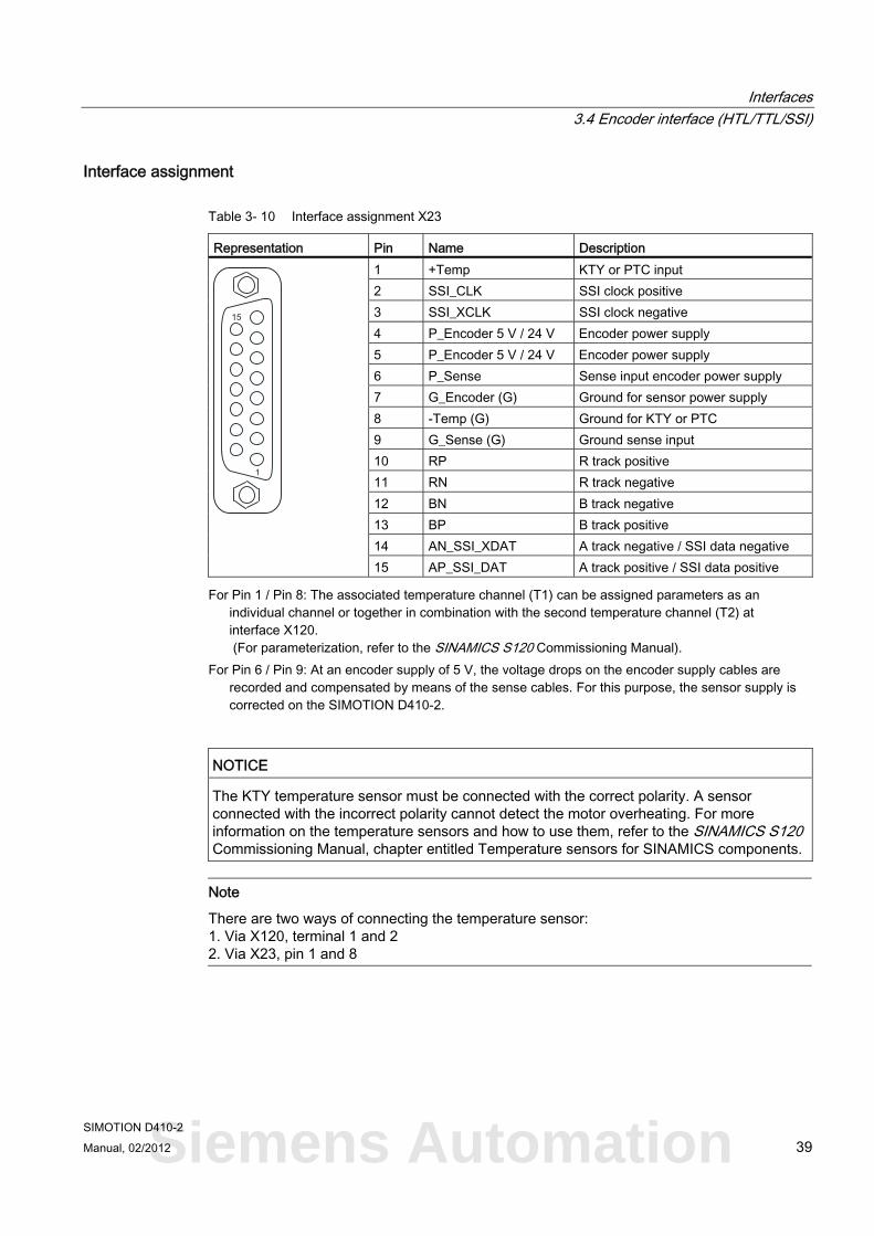
Interface assignment
Table 3- 10 Interface assignment X23
Representation Pin Name Description 1 +Temp KTY or PTC input 2 SSI_CLK SSI clock positive 3 SSI_XCLK SSI clock negative 4 P_Encoder 5 V / 24 V Encoder power supply 5 P_Encoder 5 V / 24 V Encoder power supply 6 P_Sense Sense input encoder power supply 7 G_Encoder (G) Ground for sensor power supply 8 -Temp (G) Ground for KTY or PTC 9 G_Sense (G) Ground sense input 10 RP R track positive 11 RN R track negative 12 BN B track negative 13 BP B track positive 14 AN_SSI_XDAT A track negative / SSI data negative
15 AP_SSI_DAT A track positive / SSI data positive
For Pin 1 / Pin 8: The associated temperature channel (T1) can be assigned parameters as an individual channel or together in combination with the second temperature channel (T2) at interface X120. (For parameterization, refer to the SINAMICS S120 Commissioning Manual).
For Pin 6 / Pin 9: At an encoder supply of 5 V, the voltage drops on the encoder supply cables are recorded and compensated by means of the sense cables. For this purpose, the sensor supply is corrected on the SIMOTION D410-2.
NOTICE The KTY temperature sensor must be connected with the correct polarity. A sensor connected with the incorrect polarity cannot detect the motor overheating. For more information on the temperature sensors and how to use them, refer to the SINAMICS S120 Commissioning Manual, chapter entitled Temperature sensors for SINAMICS components.
Note
There are two ways of connecting the temperature sensor: 1. Via X120, terminal 1 and 2 2. Via X23, pin 1 and 8
Siemens Automation
Interfaces 3.4 Encoder interface (HTL/TTL/SSI)
SIMOTION D410-2 40 Manual, 02/2012
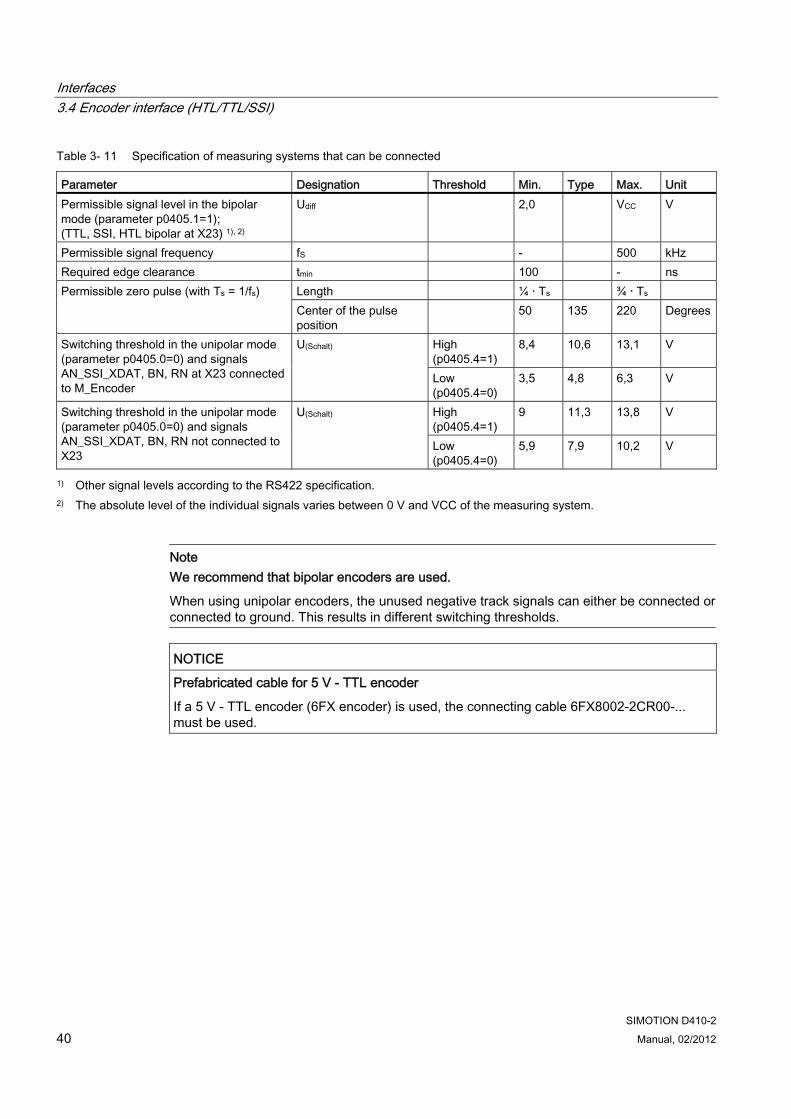
Table 3- 11 Specification of measuring systems that can be connected
Parameter Designation Threshold Min. Type Max. Unit Permissible signal level in the bipolar mode (parameter p0405.1=1); (TTL, SSI, HTL bipolar at X23) 1), 2)
Udiff 2,0 VCC V
Permissible signal frequency fS - 500 kHz Required edge clearance tmin 100 - ns
Length ¼ · Ts ¾ · Ts Permissible zero pulse (with Ts = 1/fs) Center of the pulse position
50 135 220 Degrees
High (p0405.4=1)
8,4 10,6 13,1 V Switching threshold in the unipolar mode (parameter p0405.0=0) and signals AN_SSI_XDAT, BN, RN at X23 connected to M_Encoder
U(Schalt)
Low (p0405.4=0)
3,5 4,8 6,3 V
High (p0405.4=1)
9 11,3 13,8 V Switching threshold in the unipolar mode (parameter p0405.0=0) and signals AN_SSI_XDAT, BN, RN not connected to X23
U(Schalt)
Low (p0405.4=0)
5,9 7,9 10,2 V
1) Other signal levels according to the RS422 specification. 2) The absolute level of the individual signals varies between 0 V and VCC of the measuring system.
Note We recommend that bipolar encoders are used.
When using unipolar encoders, the unused negative track signals can either be connected or connected to ground. This results in different switching thresholds.
NOTICE Prefabricated cable for 5 V - TTL encoder
If a 5 V - TTL encoder (6FX encoder) is used, the connecting cable 6FX8002-2CR00-... must be used.
Interfaces 3.5 Digital I/Os / temperature sensor / analog input
SIMOTION D410-2 Manual, 02/2012 41
3.5 Digital I/Os / temperature sensor / analog input
3.5.1 Properties The onboard I/Os (Onboard I/Os) of the SIMOTION D410-2 are assigned to the SINAMICS Integrated. An appropriate configuration allows the I/Os also to be used by SIMOTION.
Digital I/Os The digital I/Os at the X120, X121 and X130, X131 connectors are provided for the connection of sensors and actuators.
Following types of digital I/Os are available on the SIMOTION D410-2:
● Three fail-safe electrically-isolated digital inputs (F-DI)
(can be used alternatively as six standard digital inputs, DI 17 can also be used as EP terminal)
● One fail-safe electrically-isolated digital output (F-DO)
(can be used alternatively as one standard digital output)
● Five electrically-isolated digital inputs (DI)
● Eight high-speed non-isolated digital I/Os (DI/DO)
Assignment of the I/Os to functions can be parameterized as required. Special functions (e.g. input of measuring input and output for output cam) can also be assigned to the I/Os.
Note
For optimal noise immunity of the digital inputs, the use of shielded cables is necessary if they are to be used as • Inputs of measuring inputs or • Inputs for equivalent zero mark
Analog input The analog input at connector X131 can be parameterized as voltage or current input.
Switching between the voltage or current input using a DIP switch, refer to Switch S5.0 (Page 30).
Siemens Automation
Interfaces 3.5 Digital I/Os / temperature sensor / analog input
SIMOTION D410-2 42 Manual, 02/2012
3.5.2 Interface characteristics
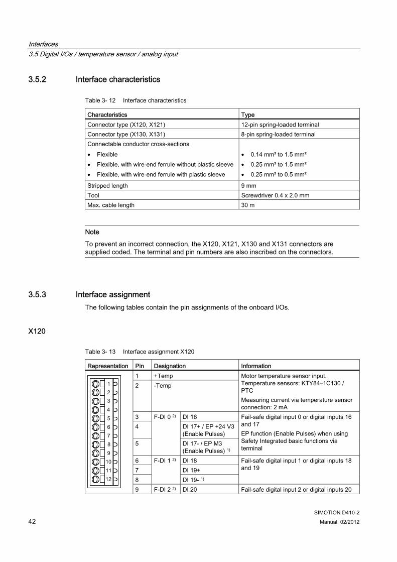
Table 3- 12 Interface characteristics
Characteristics Type Connector type (X120, X121) 12-pin spring-loaded terminal Connector type (X130, X131) 8-pin spring-loaded terminal Connectable conductor cross-sections • Flexible • Flexible, with wire-end ferrule without plastic sleeve • Flexible, with wire-end ferrule with plastic sleeve
• 0.14 mm² to 1.5 mm² • 0.25 mm² to 1.5 mm² • 0.25 mm² to 0.5 mm²
Stripped length 9 mm Tool Screwdriver 0.4 x 2.0 mm Max. cable length 30 m
Note
To prevent an incorrect connection, the X120, X121, X130 and X131 connectors are supplied coded. The terminal and pin numbers are also inscribed on the connectors.
3.5.3 Interface assignment The following tables contain the pin assignments of the onboard I/Os.
X120
Table 3- 13 Interface assignment X120
Representation Pin Designation Information 1 +Temp 2 -Temp
Motor temperature sensor input. Temperature sensors: KTY84–1C130 / PTC Measuring current via temperature sensor connection: 2 mA
3 DI 16 4 DI 17+ / EP +24 V3
(Enable Pulses) 5
F-DI 0 2)
DI 17- / EP M3 (Enable Pulses) 1)
Fail-safe digital input 0 or digital inputs 16 and 17 EP function (Enable Pulses) when using Safety Integrated basic functions via terminal
6 DI 18 7 DI 19+ 8
F-DI 1 2)
DI 19- 1)
Fail-safe digital input 1 or digital inputs 18 and 19
9 F-DI 2 2) DI 20 Fail-safe digital input 2 or digital inputs 20
Interfaces 3.5 Digital I/Os / temperature sensor / analog input
SIMOTION D410-2 Manual, 02/2012 43
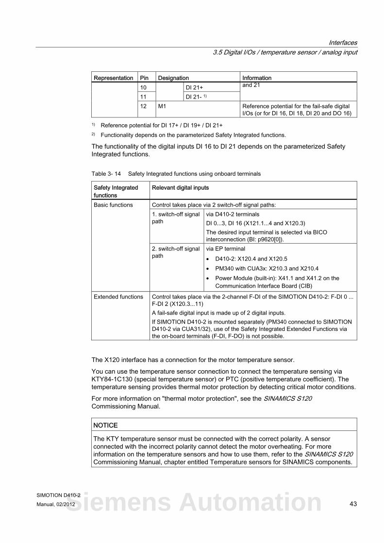
Representation Pin Designation Information 10 DI 21+ 11 DI 21- 1)
and 21
12 M1 Reference potential for the fail-safe digital I/Os (or for DI 16, DI 18, DI 20 and DO 16)
1) Reference potential for DI 17+ / DI 19+ / DI 21+ 2) Functionality depends on the parameterized Safety Integrated functions.
The functionality of the digital inputs DI 16 to DI 21 depends on the parameterized Safety Integrated functions.
Table 3- 14 Safety Integrated functions using onboard terminals
Safety Integrated functions
Relevant digital inputs
Control takes place via 2 switch-off signal paths: 1. switch-off signal path
via D410-2 terminals DI 0...3, DI 16 (X121.1...4 and X120.3) The desired input terminal is selected via BICO interconnection (BI: p9620[0]).
Basic functions
2. switch-off signal path
via EP terminal • D410-2: X120.4 and X120.5 • PM340 with CUA3x: X210.3 and X210.4 • Power Module (built-in): X41.1 and X41.2 on the
Communication Interface Board (CIB)
Extended functions Control takes place via the 2-channel F-DI of the SIMOTION D410-2: F-DI 0 ... F-DI 2 (X120.3...11) A fail-safe digital input is made up of 2 digital inputs. If SIMOTION D410-2 is mounted separately (PM340 connected to SIMOTION D410-2 via CUA31/32), use of the Safety Integrated Extended Functions via the on-board terminals (F-DI, F-DO) is not possible.
The X120 interface has a connection for the motor temperature sensor.
You can use the temperature sensor connection to connect the temperature sensing via KTY84-1C130 (special temperature sensor) or PTC (positive temperature coefficient). The temperature sensing provides thermal motor protection by detecting critical motor conditions.
For more information on "thermal motor protection", see the SINAMICS S120 Commissioning Manual.
NOTICE The KTY temperature sensor must be connected with the correct polarity. A sensor connected with the incorrect polarity cannot detect the motor overheating. For more information on the temperature sensors and how to use them, refer to the SINAMICS S120 Commissioning Manual, chapter entitled Temperature sensors for SINAMICS components.
Siemens Automation
Interfaces 3.5 Digital I/Os / temperature sensor / analog input
SIMOTION D410-2 44 Manual, 02/2012
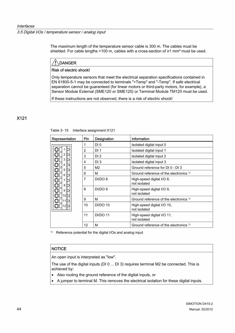
The maximum length of the temperature sensor cable is 300 m. The cables must be shielded. For cable lengths >100 m, cables with a cross-section of ≥1 mm² must be used.
DANGER Risk of electric shock!
Only temperature sensors that meet the electrical separation specifications contained in EN 61800-5-1 may be connected to terminals "+Temp" and "-Temp". If safe electrical separation cannot be guaranteed (for linear motors or third-party motors, for example), a Sensor Module External (SME120 or SME125) or Terminal Module TM120 must be used.
If these instructions are not observed, there is a risk of electric shock!
X121
Table 3- 15 Interface assignment X121
Representation Pin Designation Information 1 DI 0 Isolated digital input 0 2 DI 1 Isolated digital input 1 3 DI 2 Isolated digital input 2 4 DI 3 Isolated digital input 3 5 M2 Ground reference for DI 0 - DI 3 6 M Ground reference of the electronics 1) 7 DI/DO 8 High-speed digital I/O 8,
not isolated 8 DI/DO 9 High-speed digital I/O 9,
not isolated 9 M Ground reference of the electronics 1) 10 DI/DO 10 High-speed digital I/O 10,
not isolated 11 DI/DO 11 High-speed digital I/O 11,
not isolated
12 M Ground reference of the electronics 1)
1) Reference potential for the digital I/Os and analog input
NOTICE An open input is interpreted as "low".
The use of the digital inputs (DI 0 ... DI 3) requires terminal M2 be connected. This is achieved by: • Also routing the ground reference of the digital inputs, or • A jumper to terminal M. This removes the electrical isolation for these digital inputs.
Interfaces 3.5 Digital I/Os / temperature sensor / analog input
SIMOTION D410-2 Manual, 02/2012 45
X130
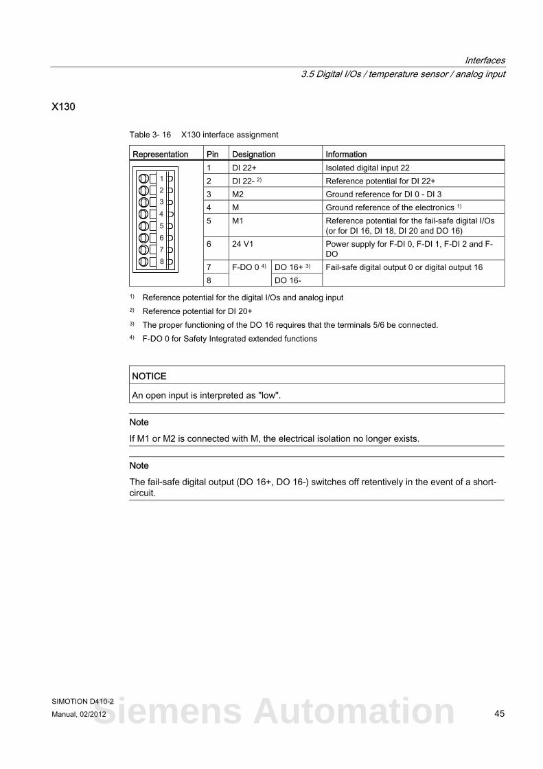
Table 3- 16 X130 interface assignment
Representation Pin Designation Information 1 DI 22+ Isolated digital input 22 2 DI 22- 2) Reference potential for DI 22+ 3 M2 Ground reference for DI 0 - DI 3 4 M Ground reference of the electronics 1) 5 M1 Reference potential for the fail-safe digital I/Os
(or for DI 16, DI 18, DI 20 and DO 16) 6 24 V1 Power supply for F-DI 0, F-DI 1, F-DI 2 and F-
DO 7 DO 16+ 3) 8
F-DO 0 4) DO 16-
Fail-safe digital output 0 or digital output 16
1) Reference potential for the digital I/Os and analog input 2) Reference potential for DI 20+ 3) The proper functioning of the DO 16 requires that the terminals 5/6 be connected. 4) F-DO 0 for Safety Integrated extended functions
NOTICE An open input is interpreted as "low".
Note
If M1 or M2 is connected with M, the electrical isolation no longer exists.
Note
The fail-safe digital output (DO 16+, DO 16-) switches off retentively in the event of a short-circuit.
Siemens Automation
Interfaces 3.5 Digital I/Os / temperature sensor / analog input
SIMOTION D410-2 46 Manual, 02/2012
X131
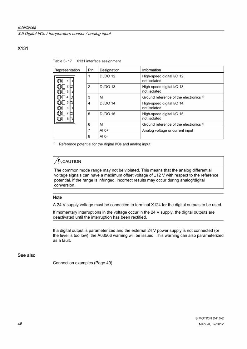
Table 3- 17 X131 interface assignment
Representation Pin Designation Information 1 DI/DO 12 High-speed digital I/O 12,
not isolated 2 DI/DO 13 High-speed digital I/O 13,
not isolated 3 M Ground reference of the electronics 1) 4 DI/DO 14 High-speed digital I/O 14,
not isolated 5 DI/DO 15 High-speed digital I/O 15,
not isolated 6 M Ground reference of the electronics 1) 7 AI 0+
8 AI 0- Analog voltage or current input
1) Reference potential for the digital I/Os and analog input
CAUTION The common mode range may not be violated. This means that the analog differential voltage signals can have a maximum offset voltage of ±12 V with respect to the reference potential. If the range is infringed, incorrect results may occur during analog/digital conversion.
Note
A 24 V supply voltage must be connected to terminal X124 for the digital outputs to be used.
If momentary interruptions in the voltage occur in the 24 V supply, the digital outputs are deactivated until the interruption has been rectified.
If a digital output is parameterized and the external 24 V power supply is not connected (or the level is too low), the A03506 warning will be issued. This warning can also parameterized as a fault.
See also Connection examples (Page 49)
Interfaces 3.5 Digital I/Os / temperature sensor / analog input
SIMOTION D410-2 Manual, 02/2012 47
3.5.4 Use of the interfaces
Fail-safe digital I/Os (F-DI/F-DO) The SIMOTION D410-2 provides three fail-safe isolated digital inputs (F-DI) and one fail-safe isolated digital output (F-DO):
● An F-DI consists of a digital input and a second digital input to which the cathode of the optocoupler is connected.
Each of the F-DIs can also be used as two standard digital inputs, e.g. the use of the F-DI 0 as DI 16 and DI 17.
● The F-DO 0 can also used as a standard digital output.
The F-DO 0 consists of a high-side switch and a low-side switch. For applications without the safety function, the high-side switch may be used as an additional digital output. The low-side switch is not available.
Note
The following safety functions are available for SIMOTION D410-2 DP: • Safety Integrated Basic Functions via the EP terminals • Safety Integrated extended functions via onboard I/Os (3 F-DI and 1 F-DO) • Safety Integrated Extended Functions with TM54F • Safety Integrated basic and extended functions via secure communication from
"PROFIsafe to PROFIBUS" Control (F logic) is via a SIMATIC F-CPU which is connected to PROFIsafe via PROFIBUS (e.g. a CPU 317F-2 DP)
For further information on Safety Integrated, see the SINAMICS S120 Safety Integrated Function Manual.
Digital inputs (DI) The SIMOTION D410-2 provides five digital inputs (DI).
The electrically isolated inputs can be used as freely addressable inputs.
Note
An open input is interpreted as "low".
For the DI 22 digital input to function correctly, the coupled reference potential (DI 22-) must be connected. The following options are available: • Connect the coupled reference potential of the digital input to M1, M2 or M.
This assigns the input to the potential of the associated pin. • Create a bridge between terminal M and terminal M1 or M2.
Caution: This will cancel the electrical isolation for this digital input!
Siemens Automation
Interfaces 3.5 Digital I/Os / temperature sensor / analog input
SIMOTION D410-2 48 Manual, 02/2012
Bidirectional digital I/Os (DI/DO) The SIMOTION D410-2 provides eight bidirectional digital I/Os (DI/DO) that can be parameterized channel-specific as digital input or output.
This produces the following usage options for the parameterization of the DI/DO:
Table 3- 18 DI/DO usage possibilities
DI/DO Interface Use Parameterization of the DI/DO as digital inputs: DI/DO 8 to DI/DO 15 X121, X131 "Fast inputs" for measuring inputs 1) or homing inputs DI/DO 8 to DI/DO 15 X121, X131 Freely addressable inputs Parameterization of the DI/DO as digital outputs: DI/DO 8 to DI/DO 15 X121, X131 "High-speed" outputs of output cams DI/DO 8 to DI/DO 15 X121, X131 Freely addressable outputs
1) With a signal edge at the relevant input, the current actual values of one or more encoders are measured with positioning accuracy to determine lengths and distances. The assignment of the inputs is not fixed, and the special use is activated in the SIMOTION SCOUT engineering system.
Note
An additional external electronics power supply via terminal X124 is required in two cases: • If the digital outputs DO 8 to DO 15 are in use, the power supply needs to be connected
to X124. • The power module provides the electronics power supply of the SIMOTION D410-2. If the
SIMOTION D410-2 needs to remain functional when the power module is switched off, X124 must be used for the electronics power supply.
Additional references For information on configuring the digital I/Os as freely addressable I/Os, inputs of measuring inputs or outputs of output cams, see the SIMOTION D410-2 Commissioning and Hardware Installation Manual.
For information on the configuration and function of the measuring input and output cam technology objects, refer to the SIMOTION Output Cams and Measuring Inputs Function Manual.
Interfaces 3.5 Digital I/Os / temperature sensor / analog input
SIMOTION D410-2 Manual, 02/2012 49
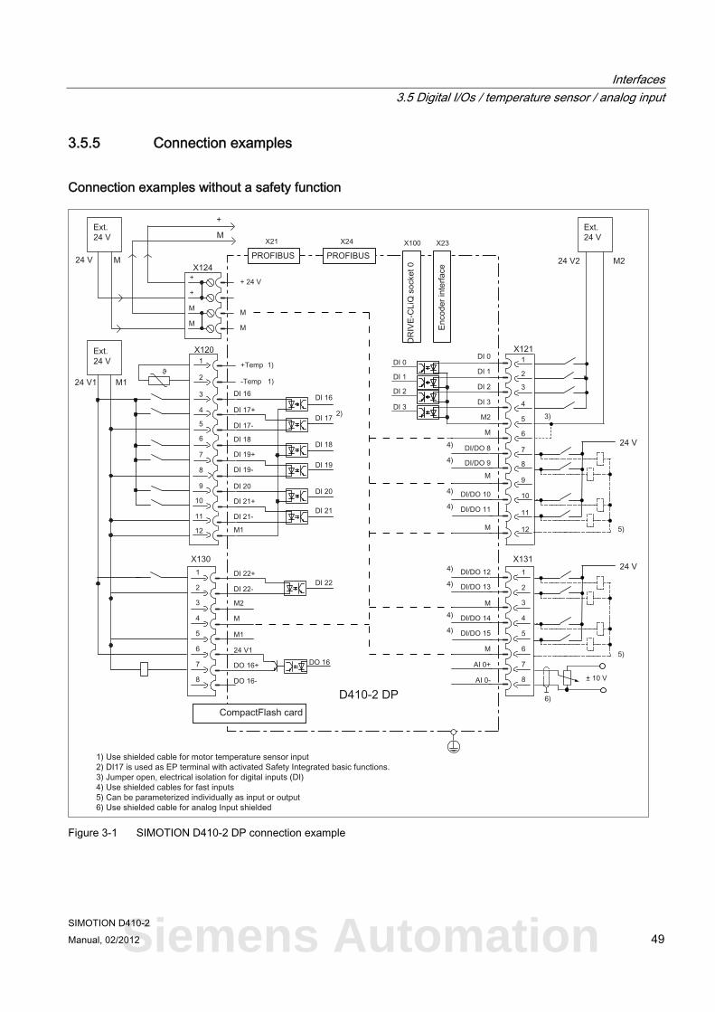
3.5.5 Connection examples
Connection examples without a safety function
Figure 3-1 SIMOTION D410-2 DP connection example
Siemens Automation
Interfaces 3.5 Digital I/Os / temperature sensor / analog input
SIMOTION D410-2 50 Manual, 02/2012
+
+M 1
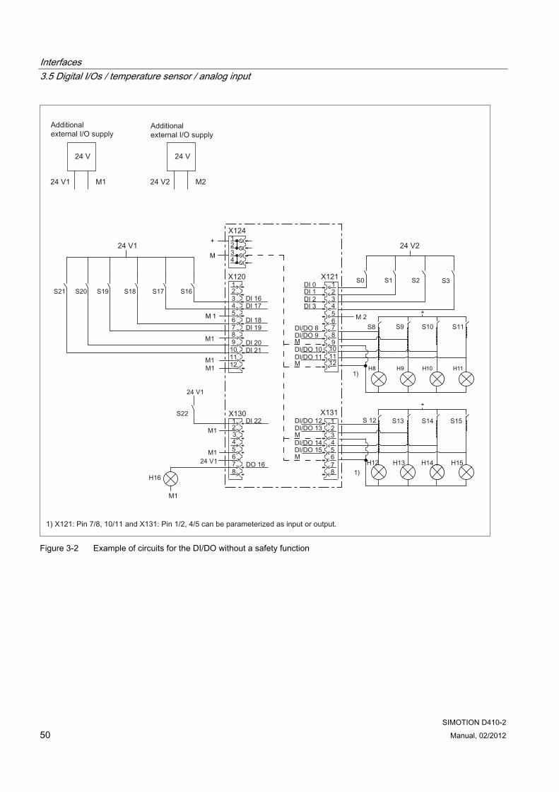
Figure 3-2 Example of circuits for the DI/DO without a safety function
Interfaces 3.5 Digital I/Os / temperature sensor / analog input
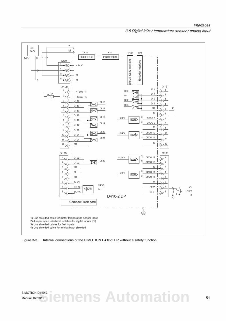
SIMOTION D410-2 Manual, 02/2012 51
Figure 3-3 Internal connections of the SIMOTION D410-2 DP without a safety function
Siemens Automation
Interfaces 3.5 Digital I/Os / temperature sensor / analog input
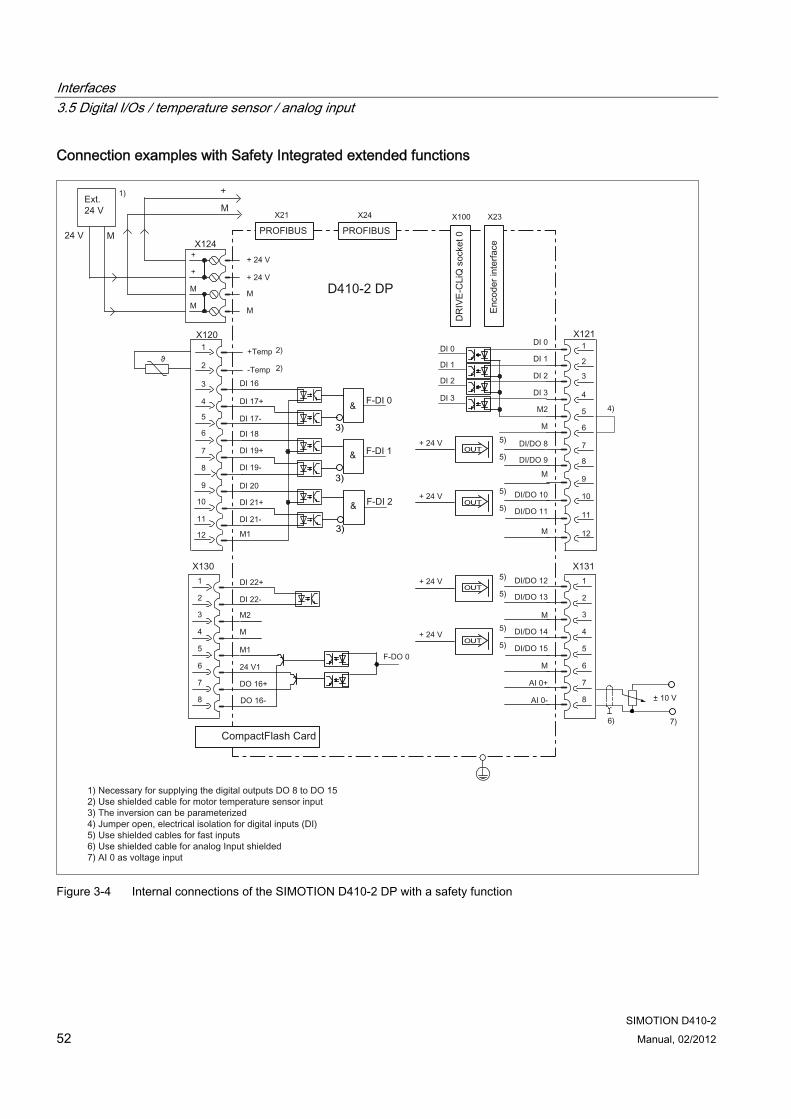
SIMOTION D410-2 52 Manual, 02/2012
Connection examples with Safety Integrated extended functions
Figure 3-4 Internal connections of the SIMOTION D410-2 DP with a safety function
Interfaces 3.5 Digital I/Os / temperature sensor / analog input
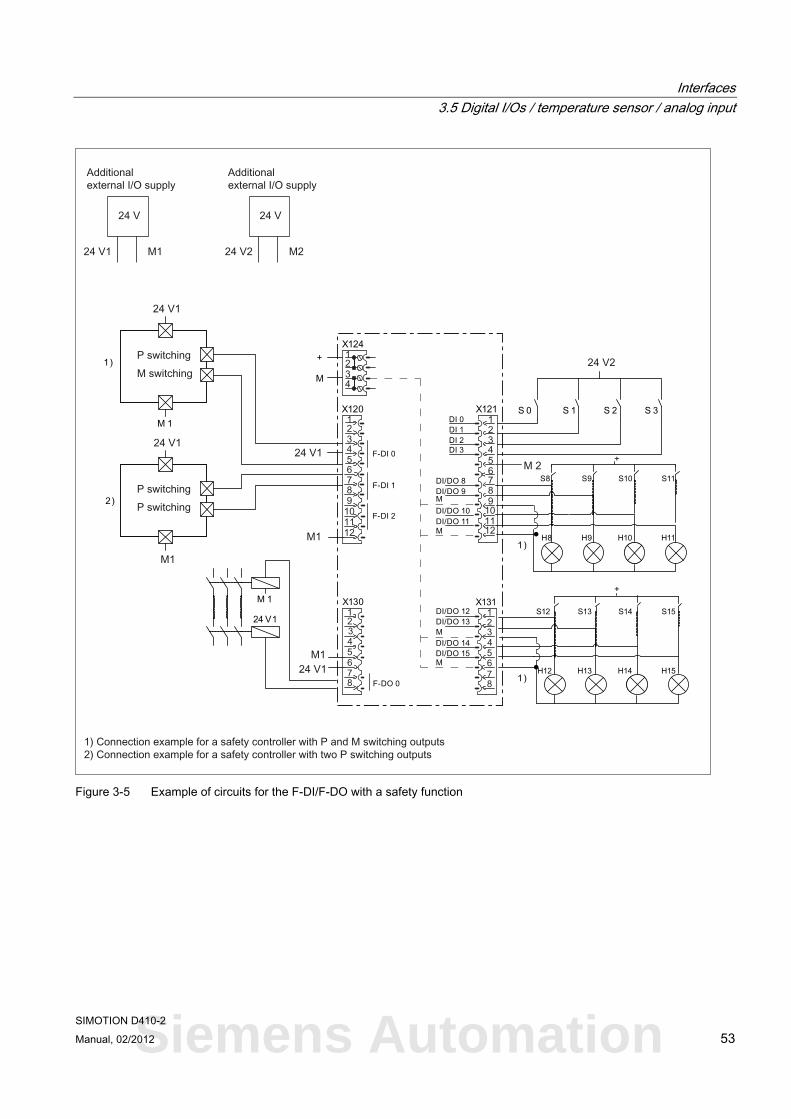
SIMOTION D410-2 Manual, 02/2012 53
+
+
S 3S 2S 1S 0
24 V1
M 1
Figure 3-5 Example of circuits for the F-DI/F-DO with a safety function
Siemens Automation
Interfaces 3.6 Power supply
SIMOTION D410-2 54 Manual, 02/2012
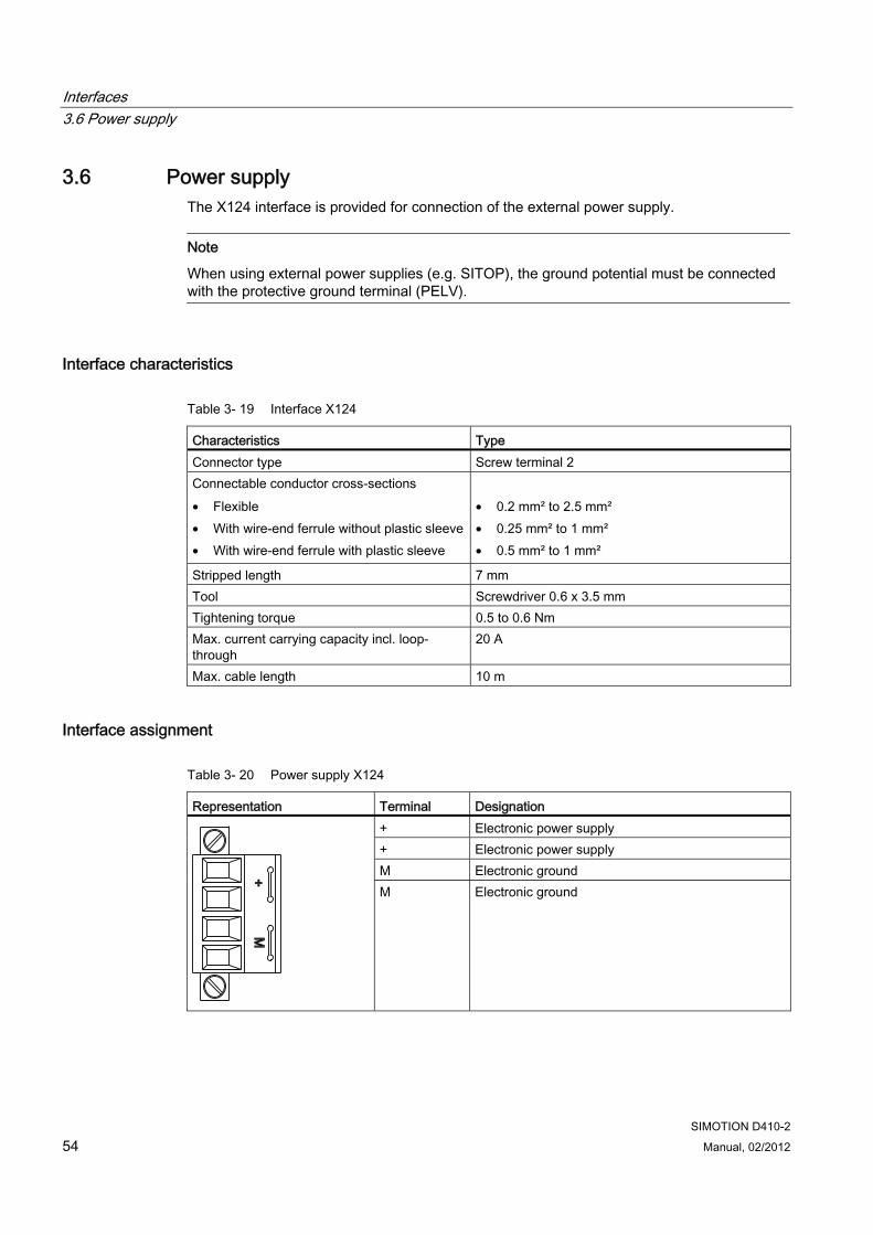
3.6 Power supply The X124 interface is provided for connection of the external power supply.
Note
When using external power supplies (e.g. SITOP), the ground potential must be connected with the protective ground terminal (PELV).
Interface characteristics
Table 3- 19 Interface X124
Characteristics Type Connector type Screw terminal 2 Connectable conductor cross-sections • Flexible • With wire-end ferrule without plastic sleeve• With wire-end ferrule with plastic sleeve
• 0.2 mm² to 2.5 mm² • 0.25 mm² to 1 mm² • 0.5 mm² to 1 mm²
Stripped length 7 mm Tool Screwdriver 0.6 x 3.5 mm Tightening torque 0.5 to 0.6 Nm Max. current carrying capacity incl. loop-through
20 A
Max. cable length 10 m
Interface assignment
Table 3- 20 Power supply X124
Representation Terminal Designation + Electronic power supply + Electronic power supply M Electronic ground
M Electronic ground
Interfaces 3.7 Ethernet interface
SIMOTION D410-2 Manual, 02/2012 55
Note
The power supply terminal strip must be screwed on tightly using a flat-bladed screwdriver.
Note
The 24 V is looped through via the 24 V connector. In this case, pin 1 is jumpered with pin 2, and pin 3 is jumpered with pin 4 in the connector. The maximum current can be limited through the current carrying capacity of the cable. The current carrying capacity of the cable depends, for example, on the type of cable installation (cable duct, laying on a cable rack, etc.).
3.7 Ethernet interface
Properties SIMOTION D410-2 has an X127 interface for connection to Industrial Ethernet. Industrial Ethernet is a communication network with a transmission rate of 10/100 Mbit/s.
SIMOTION D410-2 offers the following functions via the Ethernet interface:
● PROFINET basic services (e.g. DCP, LLDP, SNMP)
Although these PROFINET basic services provide uniform functions for the address assignment and diagnostics, they do not provide PROFINET IO communication for the connection of drives or I/O modules, for example.
● Communication with STEP 7 and SIMOTION SCOUT
● Communication between SIMOTION and SIMATIC NET OPC
The "SIMATIC NET SOFTNET-S7 (S7-OPC server)" software must be installed on the PG/PC for this function.
● Connection of HMI systems
● Communication with other devices over TCP/IP or UDP communication
● IT communication (via SIMOTION IT DIAG, SIMOTION IT OPC XML-DA, SIMOTION IT Virtual Machine)
For more information regarding the software packages, see Catalog PM 21, refer to the list of references (separate document) for the order number.
Siemens Automation
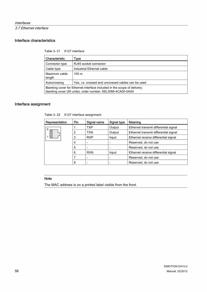
Interfaces 3.7 Ethernet interface
SIMOTION D410-2 56 Manual, 02/2012
Interface characteristics
Table 3- 21 X127 interface
Characteristic Type Connector type RJ45 socket connector Cable type Industrial Ethernet cable Maximum cable length
100 m
Autocrossing Yes, i.e. crossed and uncrossed cables can be used Blanking cover for Ethernet interface included in the scope of delivery; blanking cover (50 units), order number: 6SL3066-4CA00-0AA0
Interface assignment
Table 3- 22 X127 interface assignment
Representation Pin Signal name Signal type Meaning 1 TXP Output Ethernet transmit differential signal 2 TXN Output Ethernet transmit differential signal 3 RXP Input Ethernet receive differential signal 4 - - Reserved, do not use 5 - - Reserved, do not use 6 RXN Input Ethernet receive differential signal 7 - - Reserved, do not use
8 - - Reserved, do not use
Note
The MAC address is on a printed label visible from the front.

Interfaces 3.8 Measuring sockets
SIMOTION D410-2 Manual, 02/2012 57
3.8 Measuring sockets
Properties The T0 - T2 measuring sockets are used to output analog signals. Any interconnectable signal can be output via SINAMICS on every measuring socket on the control unit.
Note
The measuring sockets are suited for multiple-spring wire connectors with a diameter of 2 mm.
Interface characteristics
Table 3- 23 T0, T1 and T2 interfaces
Characteristic Type Connector type 2 mm sockets Voltage 0 V to 5 V Resolution 8-bit Load current max. 3 mA Sustained short-circuit proof Reference potential is M terminal
Interface assignment
Table 3- 24 Interface assignments T0, T1 and T2
Representation Pin Designation T0 Measuring socket 0 T1 Measuring socket 1 T2 Measuring socket 2
M Ground
Siemens Automation
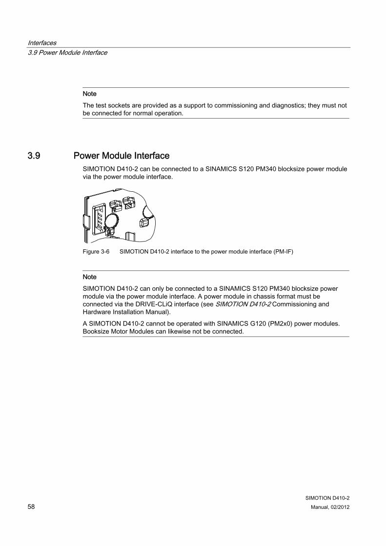
Interfaces 3.9 Power Module Interface
SIMOTION D410-2 58 Manual, 02/2012
Note
The test sockets are provided as a support to commissioning and diagnostics; they must not be connected for normal operation.
3.9 Power Module Interface SIMOTION D410-2 can be connected to a SINAMICS S120 PM340 blocksize power module via the power module interface.
Figure 3-6 SIMOTION D410-2 interface to the power module interface (PM-IF)
Note
SIMOTION D410-2 can only be connected to a SINAMICS S120 PM340 blocksize power module via the power module interface. A power module in chassis format must be connected via the DRIVE-CLiQ interface (see SIMOTION D410-2 Commissioning and Hardware Installation Manual).
A SIMOTION D410-2 cannot be operated with SINAMICS G120 (PM2x0) power modules. Booksize Motor Modules can likewise not be connected.
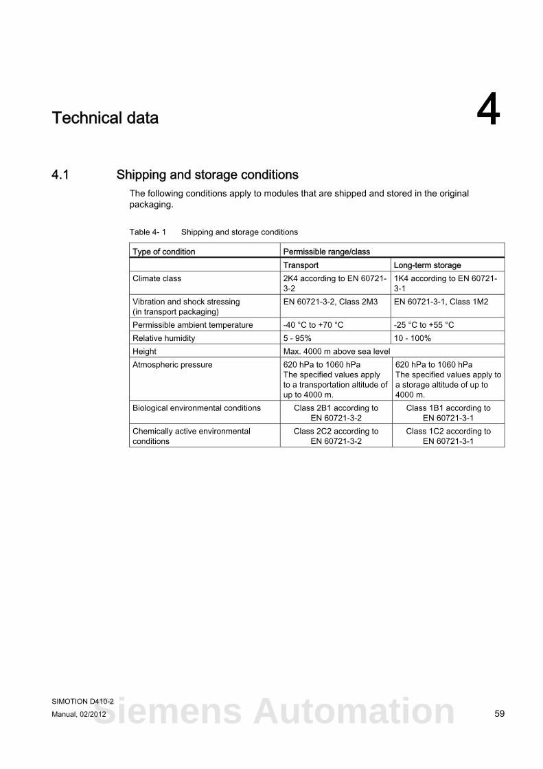
SIMOTION D410-2 Manual, 02/2012 59
Technical data 44.1 Shipping and storage conditions
The following conditions apply to modules that are shipped and stored in the original packaging.
Table 4- 1 Shipping and storage conditions
Type of condition Permissible range/class Transport Long-term storage Climate class 2K4 according to EN 60721-
3-2 1K4 according to EN 60721-3-1
Vibration and shock stressing (in transport packaging)
EN 60721-3-2, Class 2M3 EN 60721-3-1, Class 1M2
Permissible ambient temperature -40 °C to +70 °C -25 °C to +55 °C Relative humidity 5 - 95% 10 - 100% Height Max. 4000 m above sea level Atmospheric pressure 620 hPa to 1060 hPa
The specified values apply to a transportation altitude of up to 4000 m.
620 hPa to 1060 hPa The specified values apply to a storage altitude of up to 4000 m.
Biological environmental conditions Class 2B1 according to EN 60721-3-2
Class 1B1 according to EN 60721-3-1
Chemically active environmental conditions
Class 2C2 according to EN 60721-3-2
Class 1C2 according to EN 60721-3-1
Siemens Automation
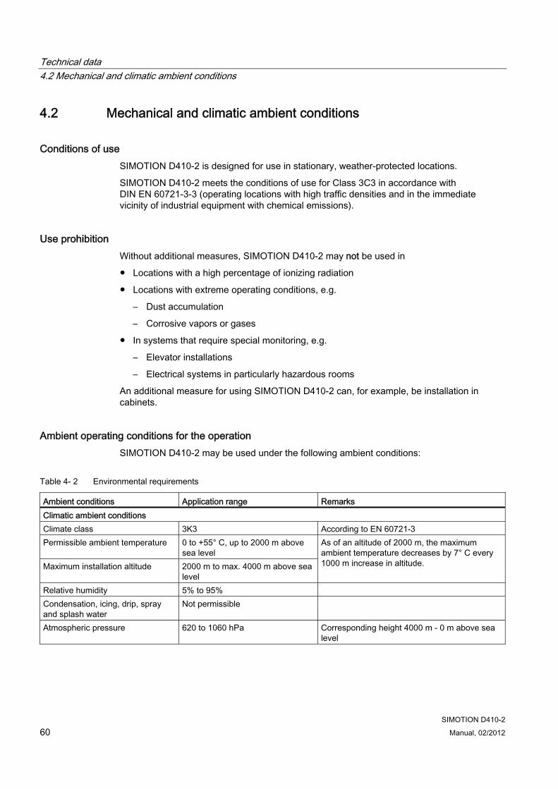
Technical data 4.2 Mechanical and climatic ambient conditions
SIMOTION D410-2 60 Manual, 02/2012
4.2 Mechanical and climatic ambient conditions
Conditions of use SIMOTION D410-2 is designed for use in stationary, weather-protected locations.
SIMOTION D410-2 meets the conditions of use for Class 3C3 in accordance with DIN EN 60721-3-3 (operating locations with high traffic densities and in the immediate vicinity of industrial equipment with chemical emissions).
Use prohibition Without additional measures, SIMOTION D410-2 may not be used in
● Locations with a high percentage of ionizing radiation
● Locations with extreme operating conditions, e.g.
– Dust accumulation
– Corrosive vapors or gases
● In systems that require special monitoring, e.g.
– Elevator installations
– Electrical systems in particularly hazardous rooms
An additional measure for using SIMOTION D410-2 can, for example, be installation in cabinets.
Ambient operating conditions for the operation SIMOTION D410-2 may be used under the following ambient conditions:
Table 4- 2 Environmental requirements
Ambient conditions Application range Remarks Climatic ambient conditions Climate class 3K3 According to EN 60721-3 Permissible ambient temperature 0 to +55° C, up to 2000 m above
sea level Maximum installation altitude 2000 m to max. 4000 m above sea
level
As of an altitude of 2000 m, the maximum ambient temperature decreases by 7° C every 1000 m increase in altitude.
Relative humidity 5% to 95% Condensation, icing, drip, spray and splash water
Not permissible
Atmospheric pressure 620 to 1060 hPa Corresponding height 4000 m - 0 m above sea level
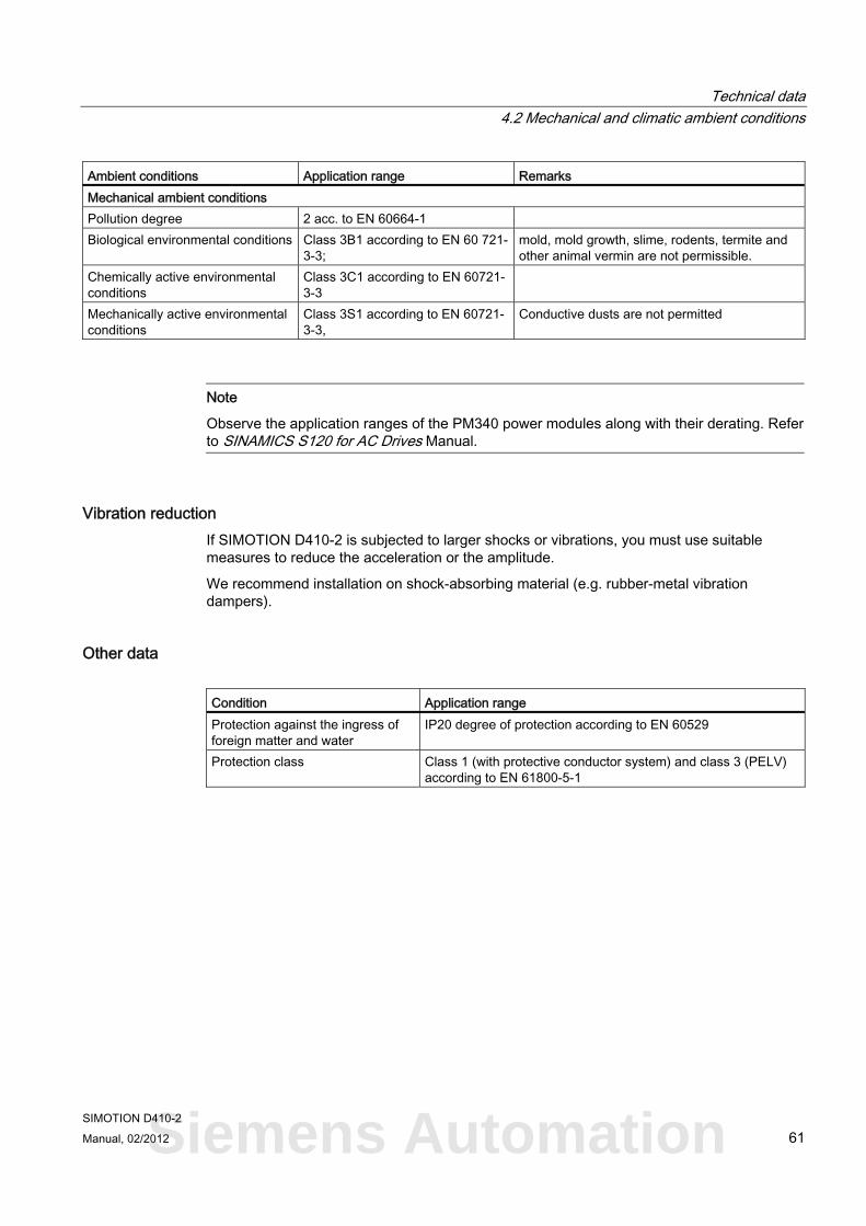
Technical data 4.2 Mechanical and climatic ambient conditions
SIMOTION D410-2 Manual, 02/2012 61
Ambient conditions Application range Remarks Mechanical ambient conditions Pollution degree 2 acc. to EN 60664-1 Biological environmental conditions Class 3B1 according to EN 60 721-
3-3; mold, mold growth, slime, rodents, termite and other animal vermin are not permissible.
Chemically active environmental conditions
Class 3C1 according to EN 60721-3-3
Mechanically active environmental conditions
Class 3S1 according to EN 60721-3-3,
Conductive dusts are not permitted
Note
Observe the application ranges of the PM340 power modules along with their derating. Refer to SINAMICS S120 for AC Drives Manual.
Vibration reduction If SIMOTION D410-2 is subjected to larger shocks or vibrations, you must use suitable measures to reduce the acceleration or the amplitude.
We recommend installation on shock-absorbing material (e.g. rubber-metal vibration dampers).
Other data Condition Application range Protection against the ingress of foreign matter and water
IP20 degree of protection according to EN 60529
Protection class Class 1 (with protective conductor system) and class 3 (PELV) according to EN 61800-5-1
Siemens Automation
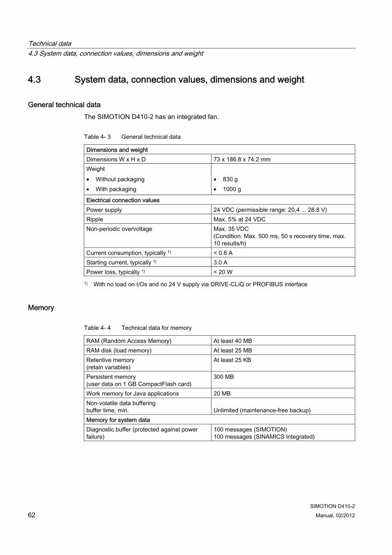
Technical data 4.3 System data, connection values, dimensions and weight
SIMOTION D410-2 62 Manual, 02/2012
4.3 System data, connection values, dimensions and weight
General technical data The SIMOTION D410-2 has an integrated fan.
Table 4- 3 General technical data
Dimensions and weight Dimensions W x H x D 73 x 186.8 x 74.2 mm Weight • Without packaging • With packaging
• 830 g • 1000 g
Electrical connection values Power supply 24 VDC (permissible range: 20,4 ... 28.8 V) Ripple Max. 5% at 24 VDC Non-periodic overvoltage Max. 35 VDC
(Condition: Max. 500 ms, 50 s recovery time, max. 10 results/h)
Current consumption, typically 1) < 0.8 A Starting current, typically 1) 3.0 A Power loss, typically 1) < 20 W
1) With no load on I/Os and no 24 V supply via DRIVE-CLiQ or PROFIBUS interface
Memory
Table 4- 4 Technical data for memory
RAM (Random Access Memory) At least 40 MB RAM disk (load memory) At least 25 MB Retentive memory (retain variables)
At least 25 KB
Persistent memory (user data on 1 GB CompactFlash card)
300 MB
Work memory for Java applications 20 MB Non-volatile data buffering buffer time, min.
Unlimited (maintenance-free backup)
Memory for system data Diagnostic buffer (protected against power failure)
100 messages (SIMOTION) 100 messages (SINAMICS Integrated)
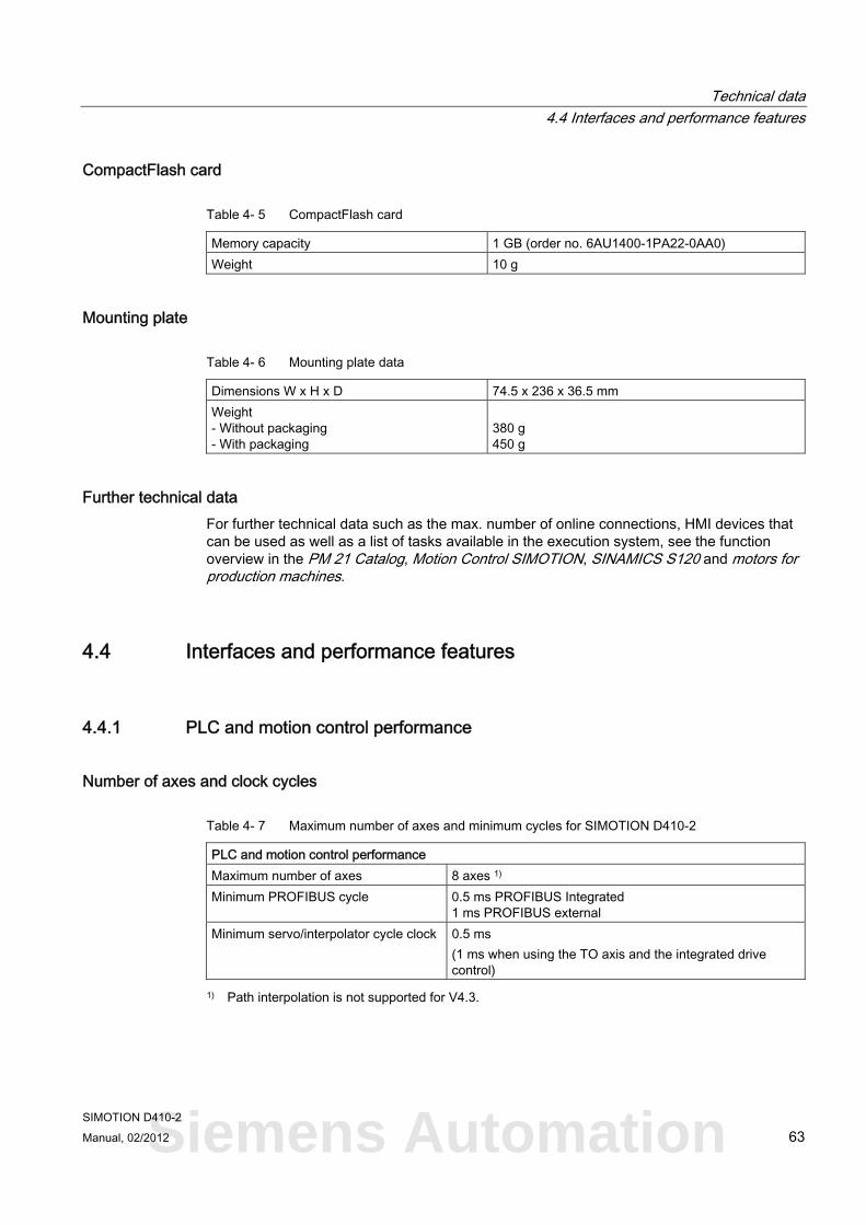
Technical data 4.4 Interfaces and performance features
SIMOTION D410-2 Manual, 02/2012 63
CompactFlash card
Table 4- 5 CompactFlash card
Memory capacity 1 GB (order no. 6AU1400-1PA22-0AA0) Weight 10 g
Mounting plate
Table 4- 6 Mounting plate data
Dimensions W x H x D 74.5 x 236 x 36.5 mm Weight - Without packaging - With packaging
380 g 450 g
Further technical data For further technical data such as the max. number of online connections, HMI devices that can be used as well as a list of tasks available in the execution system, see the function overview in the PM 21 Catalog, Motion Control SIMOTION, SINAMICS S120 and motors for production machines.
4.4 Interfaces and performance features
4.4.1 PLC and motion control performance
Number of axes and clock cycles
Table 4- 7 Maximum number of axes and minimum cycles for SIMOTION D410-2
PLC and motion control performance Maximum number of axes 8 axes 1) Minimum PROFIBUS cycle 0.5 ms PROFIBUS Integrated
1 ms PROFIBUS external Minimum servo/interpolator cycle clock 0.5 ms
(1 ms when using the TO axis and the integrated drive control)
1) Path interpolation is not supported for V4.3.
Siemens Automation
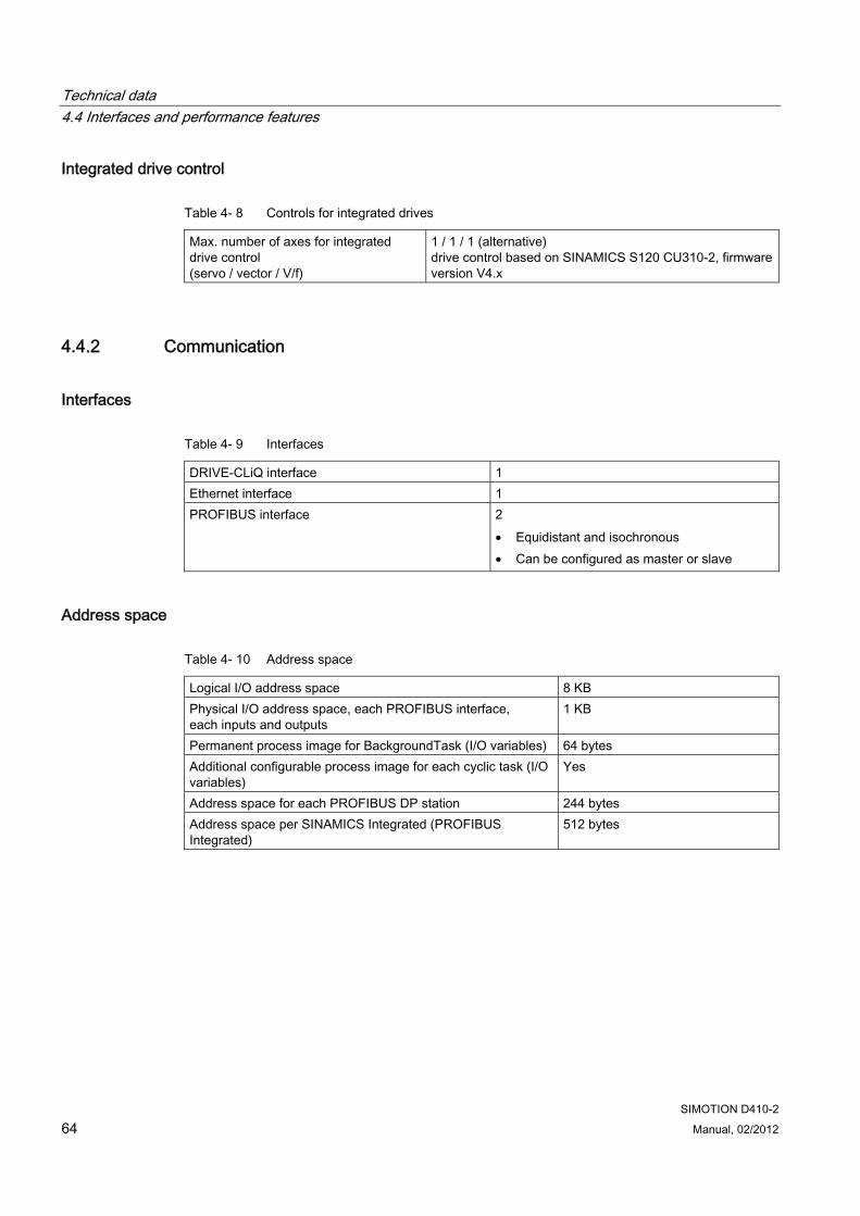
Technical data 4.4 Interfaces and performance features
SIMOTION D410-2 64 Manual, 02/2012
Integrated drive control
Table 4- 8 Controls for integrated drives
Max. number of axes for integrated drive control (servo / vector / V/f)
1 / 1 / 1 (alternative) drive control based on SINAMICS S120 CU310-2, firmware version V4.x
4.4.2 Communication
Interfaces
Table 4- 9 Interfaces
DRIVE-CLiQ interface 1 Ethernet interface 1 PROFIBUS interface 2
• Equidistant and isochronous • Can be configured as master or slave
Address space
Table 4- 10 Address space
Logical I/O address space 8 KB Physical I/O address space, each PROFIBUS interface, each inputs and outputs
1 KB
Permanent process image for BackgroundTask (I/O variables) 64 bytes Additional configurable process image for each cyclic task (I/O variables)
Yes
Address space for each PROFIBUS DP station 244 bytes Address space per SINAMICS Integrated (PROFIBUS Integrated)
512 bytes
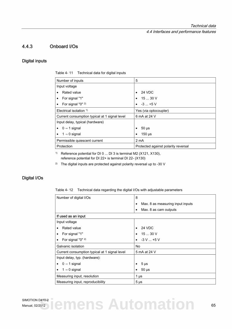
Technical data 4.4 Interfaces and performance features
SIMOTION D410-2 Manual, 02/2012 65
4.4.3 Onboard I/Os
Digital inputs
Table 4- 11 Technical data for digital inputs
Number of inputs 5 Input voltage • Rated value • For signal "1" • For signal "0" 2)
• 24 VDC • 15 ... 30 V • -3 ... +5 V
Electrical isolation 1) Yes (via optocoupler) Current consumption typical at 1 signal level 6 mA at 24 V Input delay, typical (hardware) • 0 → 1 signal • 1 → 0 signal
• 50 μs • 150 μs
Permissible quiescent current 2 mA Protection Protected against polarity reversal
1) Reference potential for DI 0 ... DI 3 is terminal M2 (X121, X130), reference potential for DI 22+ is terminal DI 22- (X130)
2) The digital inputs are protected against polarity reversal up to -30 V
Digital I/Os
Table 4- 12 Technical data regarding the digital I/Os with adjustable parameters
Number of digital I/Os 8 • Max. 8 as measuring input inputs • Max. 8 as cam outputs
If used as an input Input voltage • Rated value • For signal "1" • For signal "0" 2)
• 24 VDC • 15 ... 30 V • -3 V ... +5 V
Galvanic isolation No Current consumption typical at 1 signal level 5 mA at 24 V Input delay, typ. (hardware): • 0 → 1 signal • 1 → 0 signal
• 5 μs • 50 μs
Measuring input, resolution 1 μs Measuring input, reproducibility 5 μs
Siemens Automation
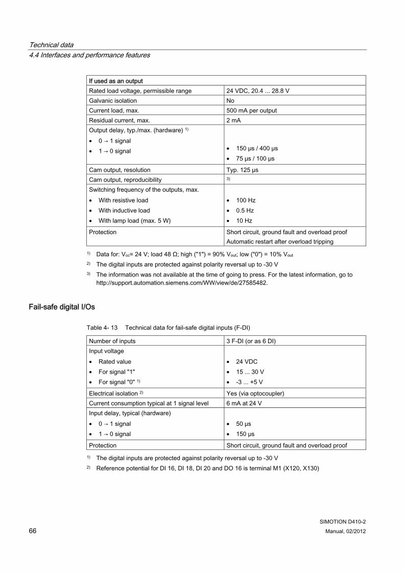
Technical data 4.4 Interfaces and performance features
SIMOTION D410-2 66 Manual, 02/2012
If used as an output Rated load voltage, permissible range 24 VDC, 20.4 ... 28.8 V Galvanic isolation No Current load, max. 500 mA per output Residual current, max. 2 mA Output delay, typ./max. (hardware) 1) • 0 → 1 signal • 1 → 0 signal
• 150 μs / 400 μs • 75 μs / 100 μs
Cam output, resolution Typ. 125 µs Cam output, reproducibility 3) Switching frequency of the outputs, max. • With resistive load • With inductive load • With lamp load (max. 5 W)
• 100 Hz • 0.5 Hz • 10 Hz
Protection Short circuit, ground fault and overload proof Automatic restart after overload tripping
1) Data for: Vcc= 24 V; load 48 Ω; high ("1") = 90% Vout; low ("0") = 10% Vout 2) The digital inputs are protected against polarity reversal up to -30 V 3) The information was not available at the time of going to press. For the latest information, go to
http://support.automation.siemens.com/WW/view/de/27585482.
Fail-safe digital I/Os
Table 4- 13 Technical data for fail-safe digital inputs (F-DI)
Number of inputs 3 F-DI (or as 6 DI) Input voltage • Rated value • For signal "1" • For signal "0" 1)
• 24 VDC • 15 ... 30 V • -3 ... +5 V
Electrical isolation 2) Yes (via optocoupler) Current consumption typical at 1 signal level 6 mA at 24 V Input delay, typical (hardware) • 0 → 1 signal • 1 → 0 signal
• 50 μs • 150 μs
Protection Short circuit, ground fault and overload proof
1) The digital inputs are protected against polarity reversal up to -30 V 2) Reference potential for DI 16, DI 18, DI 20 and DO 16 is terminal M1 (X120, X130)
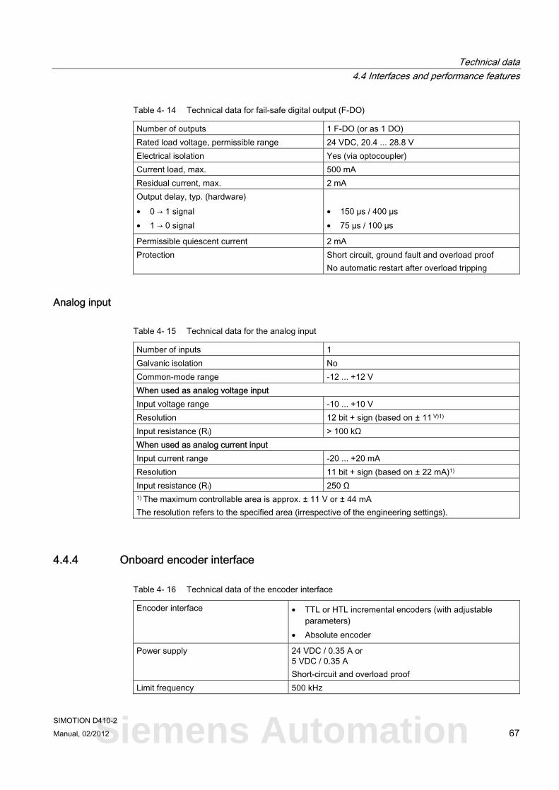
Technical data 4.4 Interfaces and performance features
SIMOTION D410-2 Manual, 02/2012 67
Table 4- 14 Technical data for fail-safe digital output (F-DO)
Number of outputs 1 F-DO (or as 1 DO) Rated load voltage, permissible range 24 VDC, 20.4 ... 28.8 V Electrical isolation Yes (via optocoupler) Current load, max. 500 mA Residual current, max. 2 mA Output delay, typ. (hardware) • 0 → 1 signal • 1 → 0 signal
• 150 μs / 400 μs • 75 μs / 100 μs
Permissible quiescent current 2 mA Protection Short circuit, ground fault and overload proof
No automatic restart after overload tripping
Analog input
Table 4- 15 Technical data for the analog input
Number of inputs 1 Galvanic isolation No Common-mode range -12 ... +12 V When used as analog voltage input Input voltage range -10 ... +10 V Resolution 12 bit + sign (based on ± 11 V)1) Input resistance (Ri) > 100 kΩ When used as analog current input Input current range -20 ... +20 mA Resolution 11 bit + sign (based on ± 22 mA)1) Input resistance (Ri) 250 Ω 1) The maximum controllable area is approx. ± 11 V or ± 44 mA The resolution refers to the specified area (irrespective of the engineering settings).
4.4.4 Onboard encoder interface
Table 4- 16 Technical data of the encoder interface
Encoder interface • TTL or HTL incremental encoders (with adjustable parameters)
• Absolute encoder
Power supply 24 VDC / 0.35 A or 5 VDC / 0.35 A Short-circuit and overload proof
Limit frequency 500 kHz
Siemens Automation
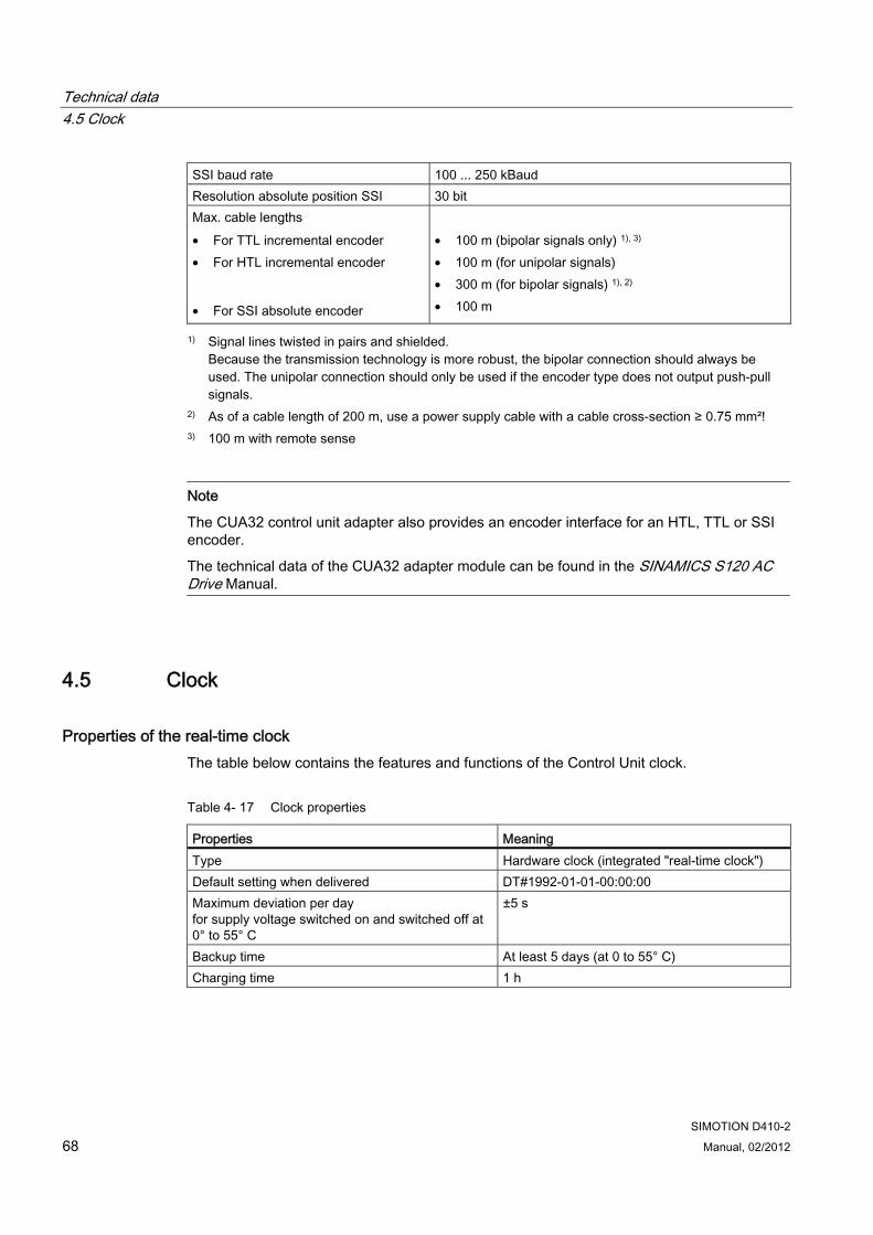
Technical data 4.5 Clock
SIMOTION D410-2 68 Manual, 02/2012
SSI baud rate 100 ... 250 kBaud Resolution absolute position SSI 30 bit Max. cable lengths • For TTL incremental encoder • For HTL incremental encoder
• For SSI absolute encoder
• 100 m (bipolar signals only) 1), 3) • 100 m (for unipolar signals) • 300 m (for bipolar signals) 1), 2) • 100 m
1) Signal lines twisted in pairs and shielded. Because the transmission technology is more robust, the bipolar connection should always be used. The unipolar connection should only be used if the encoder type does not output push-pull signals.
2) As of a cable length of 200 m, use a power supply cable with a cable cross-section ≥ 0.75 mm²! 3) 100 m with remote sense
Note
The CUA32 control unit adapter also provides an encoder interface for an HTL, TTL or SSI encoder.
The technical data of the CUA32 adapter module can be found in the SINAMICS S120 AC Drive Manual.
4.5 Clock
Properties of the real-time clock The table below contains the features and functions of the Control Unit clock.
Table 4- 17 Clock properties
Properties Meaning Type Hardware clock (integrated "real-time clock") Default setting when delivered DT#1992-01-01-00:00:00 Maximum deviation per day for supply voltage switched on and switched off at 0° to 55° C
±5 s
Backup time At least 5 days (at 0 to 55° C) Charging time 1 h

Technical data 4.5 Clock
SIMOTION D410-2 Manual, 02/2012 69
With power OFF The Control Unit clock continues to operate with the POWER OFF for the duration of the battery backup time (excluding software clock). The buffer is recharged in the POWER ON state. If the real-time clock backup time is exceeded, the time is reset. If the SIMOTION D410-2 is reset to its factory settings, the clock is also reset to the "default setting when delivered".
Siemens Automation

Technical data 4.5 Clock
SIMOTION D410-2 70 Manual, 02/2012
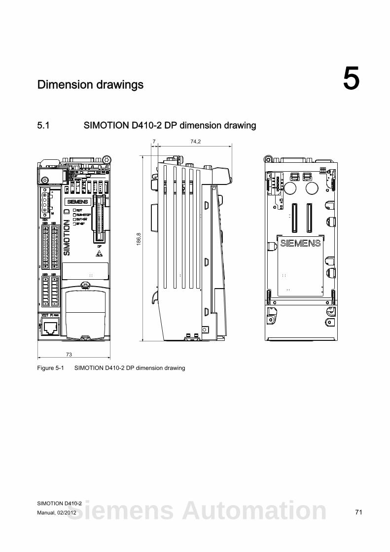
SIMOTION D410-2 Manual, 02/2012 71
Dimension drawings 55.1 SIMOTION D410-2 DP dimension drawing
Figure 5-1 SIMOTION D410-2 DP dimension drawing
Siemens Automation
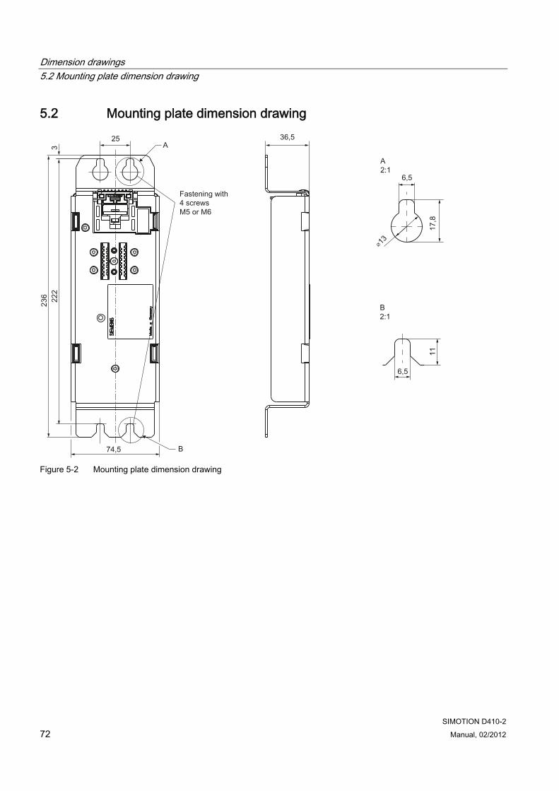
Dimension drawings 5.2 Mounting plate dimension drawing
SIMOTION D410-2 72 Manual, 02/2012
5.2 Mounting plate dimension drawing
Figure 5-2 Mounting plate dimension drawing
Dimension drawings 5.3 CAD data, dimension drawings, and circuit-diagram macros
SIMOTION D410-2 Manual, 02/2012 73
5.3 CAD data, dimension drawings, and circuit-diagram macros
Dimension drawings and CAD data Dimension drawings, as well as 2D and 3D CAD data can be found:
● In the CAD Creator at the following Internet address (http://support.automation.siemens.com/WW/view/en/30559271).
● In the DT Configurator of the Industry Mall (http://www.siemens.com/dt-configurator).
Circuit-diagram macros EPLAN circuit-diagram macros are available for the SIMOTION D410-2. The macros are supported when you create circuit diagrams. For information on how to do this, refer to: Internet address (http://support.automation.siemens.com/WW/view/en/31622426).
Siemens Automation

Dimension drawings 5.3 CAD data, dimension drawings, and circuit-diagram macros
SIMOTION D410-2 74 Manual, 02/2012
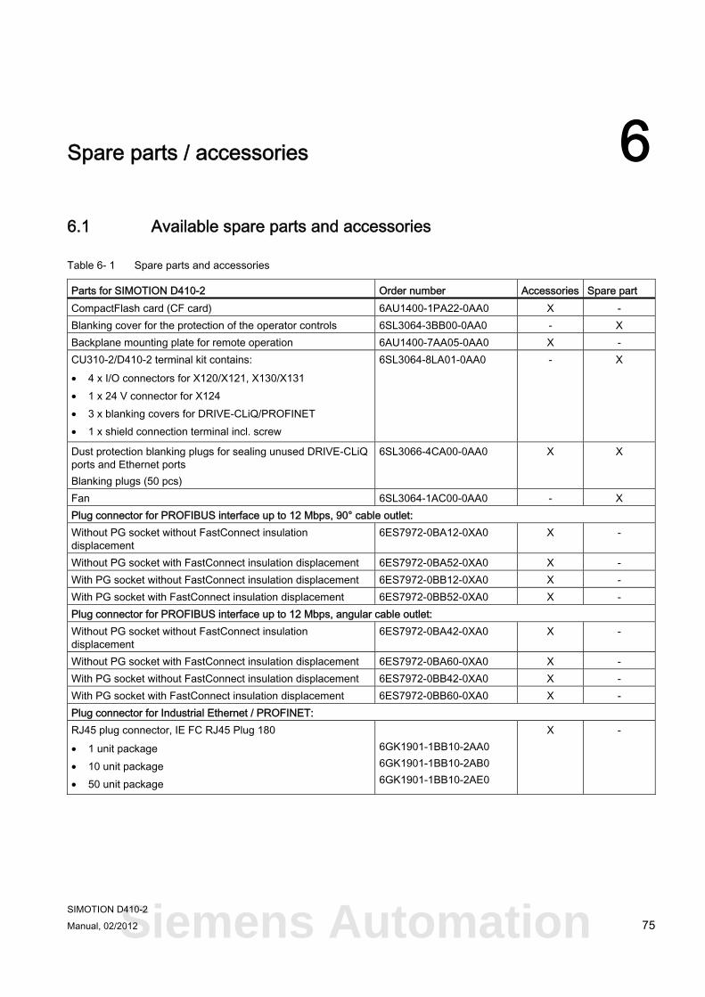
SIMOTION D410-2 Manual, 02/2012 75
Spare parts / accessories 66.1 Available spare parts and accessories
Table 6- 1 Spare parts and accessories
Parts for SIMOTION D410-2 Order number Accessories Spare part CompactFlash card (CF card) 6AU1400-1PA22-0AA0 X - Blanking cover for the protection of the operator controls 6SL3064-3BB00-0AA0 - X Backplane mounting plate for remote operation 6AU1400-7AA05-0AA0 X - CU310-2/D410-2 terminal kit contains: • 4 x I/O connectors for X120/X121, X130/X131 • 1 x 24 V connector for X124 • 3 x blanking covers for DRIVE-CLiQ/PROFINET • 1 x shield connection terminal incl. screw
6SL3064-8LA01-0AA0 - X
Dust protection blanking plugs for sealing unused DRIVE-CLiQ ports and Ethernet ports Blanking plugs (50 pcs)
6SL3066-4CA00-0AA0 X X
Fan 6SL3064-1AC00-0AA0 - X Plug connector for PROFIBUS interface up to 12 Mbps, 90° cable outlet: Without PG socket without FastConnect insulation displacement
6ES7972-0BA12-0XA0 X -
Without PG socket with FastConnect insulation displacement 6ES7972-0BA52-0XA0 X - With PG socket without FastConnect insulation displacement 6ES7972-0BB12-0XA0 X - With PG socket with FastConnect insulation displacement 6ES7972-0BB52-0XA0 X - Plug connector for PROFIBUS interface up to 12 Mbps, angular cable outlet: Without PG socket without FastConnect insulation displacement
6ES7972-0BA42-0XA0 X -
Without PG socket with FastConnect insulation displacement 6ES7972-0BA60-0XA0 X - With PG socket without FastConnect insulation displacement 6ES7972-0BB42-0XA0 X - With PG socket with FastConnect insulation displacement 6ES7972-0BB60-0XA0 X - Plug connector for Industrial Ethernet / PROFINET: RJ45 plug connector, IE FC RJ45 Plug 180 • 1 unit package • 10 unit package • 50 unit package
6GK1901-1BB10-2AA0 6GK1901-1BB10-2AB0 6GK1901-1BB10-2AE0
X -
Siemens Automation
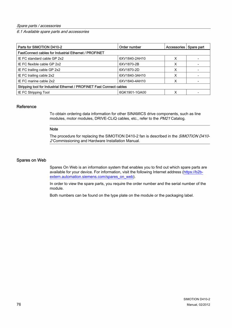
Spare parts / accessories 6.1 Available spare parts and accessories
SIMOTION D410-2 76 Manual, 02/2012
Parts for SIMOTION D410-2 Order number Accessories Spare part FastConnect cables for Industrial Ethernet / PROFINET IE FC standard cable GP 2x2 6XV1840-2AH10 X - IE FC flexible cable GP 2x2 6XV1870-2B X - IE FC trailing cable GP 2x2 6XV1870-2D X - IE FC trailing cable 2x2 6XV1840-3AH10 X - IE FC marine cable 2x2 6XV1840-4AH10 X - Stripping tool for Industrial Ethernet / PROFINET Fast Connect cables IE FC Stripping Tool 6GK1901-1GA00 X -
Reference To obtain ordering data information for other SINAMICS drive components, such as line modules, motor modules, DRIVE-CLiQ cables, etc., refer to the PM21 Catalog.
Note
The procedure for replacing the SIMOTION D410-2 fan is described in the SIMOTION D410-2 Commissioning and Hardware Installation Manual.
Spares on Web Spares On Web is an information system that enables you to find out which spare parts are available for your device. For information, visit the following Internet address (https://b2b-extern.automation.siemens.com/spares_on_web).
In order to view the spare parts, you require the order number and the serial number of the module.
Both numbers can be found on the type plate on the module or the packaging label.
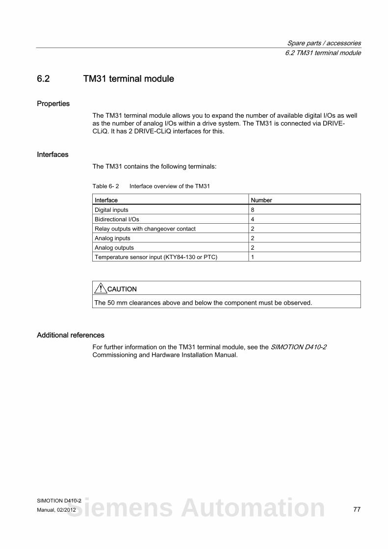
Spare parts / accessories 6.2 TM31 terminal module
SIMOTION D410-2 Manual, 02/2012 77
6.2 TM31 terminal module
Properties The TM31 terminal module allows you to expand the number of available digital I/Os as well as the number of analog I/Os within a drive system. The TM31 is connected via DRIVE-CLiQ. It has 2 DRIVE-CLiQ interfaces for this.
Interfaces The TM31 contains the following terminals:
Table 6- 2 Interface overview of the TM31
Interface Number Digital inputs 8 Bidirectional I/Os 4 Relay outputs with changeover contact 2 Analog inputs 2 Analog outputs 2 Temperature sensor input (KTY84-130 or PTC) 1
CAUTION The 50 mm clearances above and below the component must be observed.
Additional references For further information on the TM31 terminal module, see the SIMOTION D410-2 Commissioning and Hardware Installation Manual.
Siemens Automation
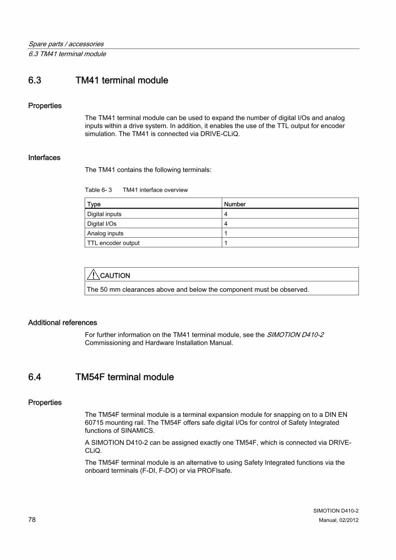
Spare parts / accessories 6.3 TM41 terminal module
SIMOTION D410-2 78 Manual, 02/2012
6.3 TM41 terminal module
Properties The TM41 terminal module can be used to expand the number of digital I/Os and analog inputs within a drive system. In addition, it enables the use of the TTL output for encoder simulation. The TM41 is connected via DRIVE-CLiQ.
Interfaces The TM41 contains the following terminals:
Table 6- 3 TM41 interface overview
Type Number Digital inputs 4 Digital I/Os 4 Analog inputs 1 TTL encoder output 1
CAUTION The 50 mm clearances above and below the component must be observed.
Additional references For further information on the TM41 terminal module, see the SIMOTION D410-2 Commissioning and Hardware Installation Manual.
6.4 TM54F terminal module
Properties The TM54F terminal module is a terminal expansion module for snapping on to a DIN EN 60715 mounting rail. The TM54F offers safe digital I/Os for control of Safety Integrated functions of SINAMICS.
A SIMOTION D410-2 can be assigned exactly one TM54F, which is connected via DRIVE-CLiQ.
The TM54F terminal module is an alternative to using Safety Integrated functions via the onboard terminals (F-DI, F-DO) or via PROFIsafe.
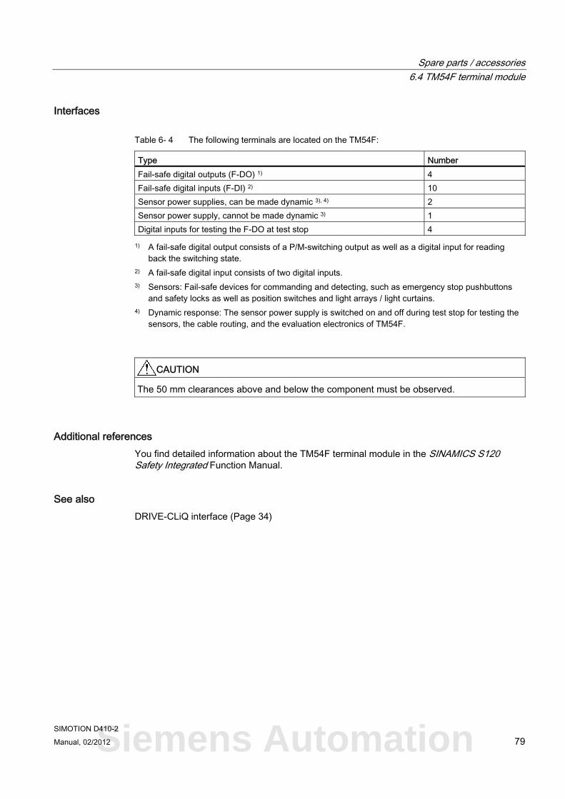
Spare parts / accessories 6.4 TM54F terminal module
SIMOTION D410-2 Manual, 02/2012 79
Interfaces
Table 6- 4 The following terminals are located on the TM54F:
Type Number Fail-safe digital outputs (F-DO) 1) 4 Fail-safe digital inputs (F-DI) 2) 10 Sensor power supplies, can be made dynamic 3), 4) 2 Sensor power supply, cannot be made dynamic 3) 1 Digital inputs for testing the F-DO at test stop 4
1) A fail-safe digital output consists of a P/M-switching output as well as a digital input for reading back the switching state.
2) A fail-safe digital input consists of two digital inputs. 3) Sensors: Fail-safe devices for commanding and detecting, such as emergency stop pushbuttons
and safety locks as well as position switches and light arrays / light curtains. 4) Dynamic response: The sensor power supply is switched on and off during test stop for testing the
sensors, the cable routing, and the evaluation electronics of TM54F.
CAUTION The 50 mm clearances above and below the component must be observed.
Additional references You find detailed information about the TM54F terminal module in the SINAMICS S120 Safety Integrated Function Manual.
See also DRIVE-CLiQ interface (Page 34)
Siemens Automation
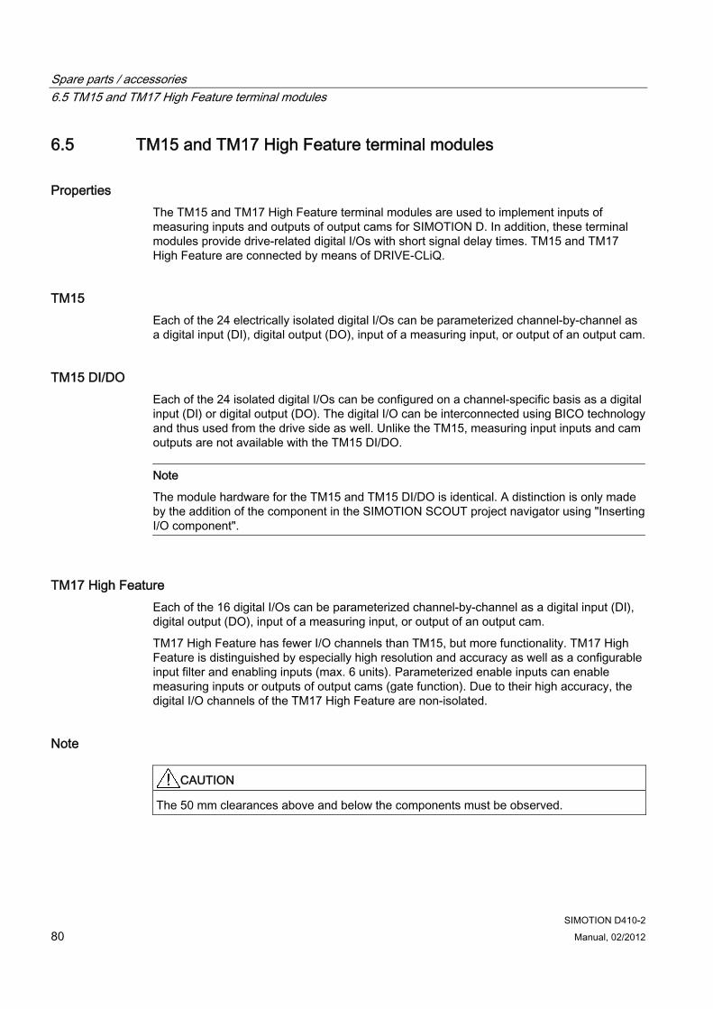
Spare parts / accessories 6.5 TM15 and TM17 High Feature terminal modules
SIMOTION D410-2 80 Manual, 02/2012
6.5 TM15 and TM17 High Feature terminal modules
Properties The TM15 and TM17 High Feature terminal modules are used to implement inputs of measuring inputs and outputs of output cams for SIMOTION D. In addition, these terminal modules provide drive-related digital I/Os with short signal delay times. TM15 and TM17 High Feature are connected by means of DRIVE-CLiQ.
TM15 Each of the 24 electrically isolated digital I/Os can be parameterized channel-by-channel as a digital input (DI), digital output (DO), input of a measuring input, or output of an output cam.
TM15 DI/DO Each of the 24 isolated digital I/Os can be configured on a channel-specific basis as a digital input (DI) or digital output (DO). The digital I/O can be interconnected using BICO technology and thus used from the drive side as well. Unlike the TM15, measuring input inputs and cam outputs are not available with the TM15 DI/DO.
Note
The module hardware for the TM15 and TM15 DI/DO is identical. A distinction is only made by the addition of the component in the SIMOTION SCOUT project navigator using "Inserting I/O component".
TM17 High Feature Each of the 16 digital I/Os can be parameterized channel-by-channel as a digital input (DI), digital output (DO), input of a measuring input, or output of an output cam.
TM17 High Feature has fewer I/O channels than TM15, but more functionality. TM17 High Feature is distinguished by especially high resolution and accuracy as well as a configurable input filter and enabling inputs (max. 6 units). Parameterized enable inputs can enable measuring inputs or outputs of output cams (gate function). Due to their high accuracy, the digital I/O channels of the TM17 High Feature are non-isolated.
Note
CAUTION The 50 mm clearances above and below the components must be observed.
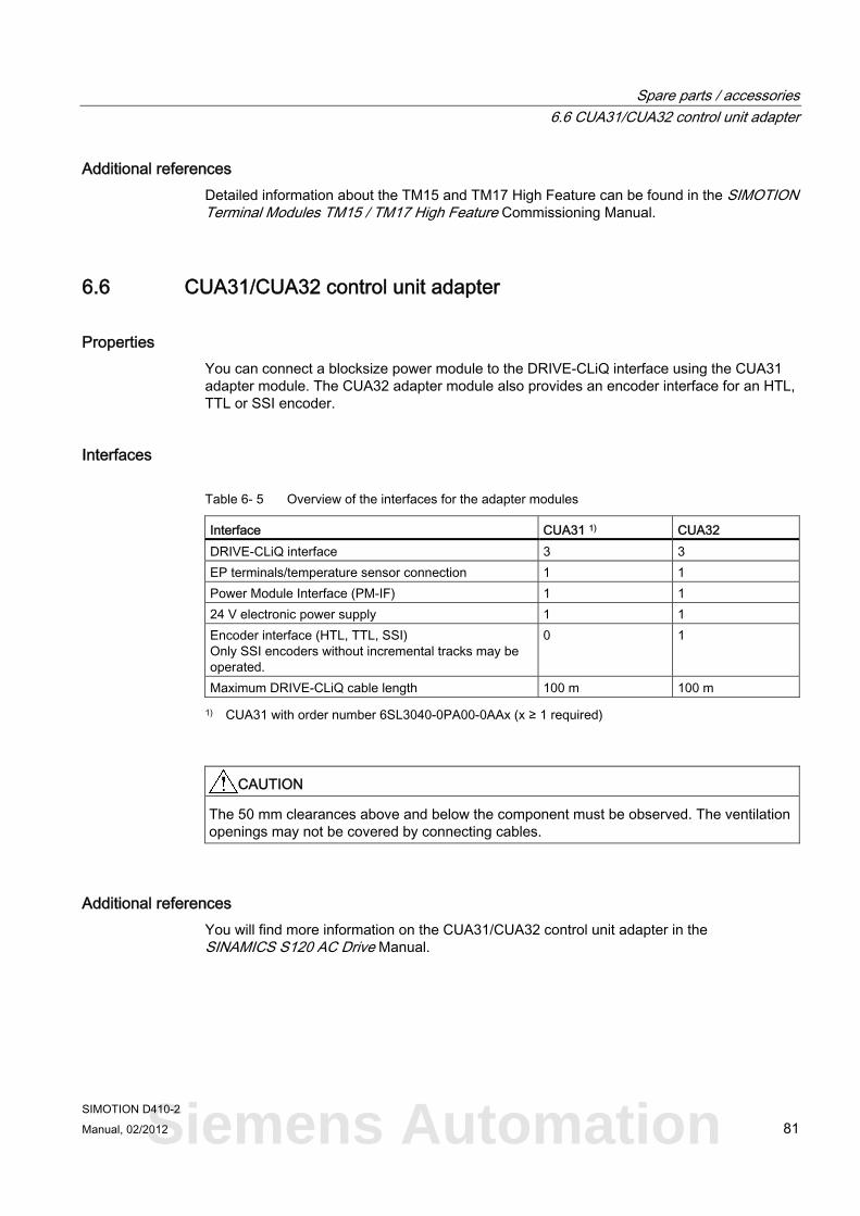
Spare parts / accessories 6.6 CUA31/CUA32 control unit adapter
SIMOTION D410-2 Manual, 02/2012 81
Additional references Detailed information about the TM15 and TM17 High Feature can be found in the SIMOTION Terminal Modules TM15 / TM17 High Feature Commissioning Manual.
6.6 CUA31/CUA32 control unit adapter
Properties You can connect a blocksize power module to the DRIVE-CLiQ interface using the CUA31 adapter module. The CUA32 adapter module also provides an encoder interface for an HTL, TTL or SSI encoder.
Interfaces
Table 6- 5 Overview of the interfaces for the adapter modules
Interface CUA31 1) CUA32 DRIVE-CLiQ interface 3 3 EP terminals/temperature sensor connection 1 1 Power Module Interface (PM-IF) 1 1 24 V electronic power supply 1 1 Encoder interface (HTL, TTL, SSI) Only SSI encoders without incremental tracks may be operated.
0 1
Maximum DRIVE-CLiQ cable length 100 m 100 m
1) CUA31 with order number 6SL3040-0PA00-0AAx (x ≥ 1 required)
CAUTION The 50 mm clearances above and below the component must be observed. The ventilation openings may not be covered by connecting cables.
Additional references You will find more information on the CUA31/CUA32 control unit adapter in the SINAMICS S120 AC Drive Manual.
Siemens Automation
Spare parts / accessories 6.7 DMC20/DME20 DRIVE-CLiQ hub
SIMOTION D410-2 82 Manual, 02/2012
6.7 DMC20/DME20 DRIVE-CLiQ hub
Properties The DMC20 and DME20 DRIVE-CLiQ hub modules are used to implement point-to-point distribution of a DRIVE-CLiQ line.
● DMC20 is the hub for the control cabinet configuration
● DME20 is the hub for use without a control cabinet (IP67 degree of protection).
The modules are particularly well suited to applications that require DRIVE-CLiQ link nodes to be removed in groups without interrupting the DRIVE-CLiQ link and therefore the data exchange.
The DMC20/DME20 is also used with a SIMOTION D410-2 DP when a second encoder is required. As an SMx sensor module and a motor with DRIVE-CLiQ interface only have one DRIVE-CLiQ interface, a DMC20/DME20 must be used for a second encoder via DRIVE-CLiQ. If a CUA31/CUA32 is used, the DMC20/DME20 is not required. Alternatively, a second encoder can also be connected via the X23 interface on the SIMOTION D410-2 DP.
CAUTION The 50 mm clearances above and below the components must be observed.
Additional references You will find detailed information about the DMC20/DME20 in the SINAMICS S120 Control Units and Additional System Components Manual.
SIMOTION D410-2 Manual, 02/2012 83
Standards and approvals AA.1 General rules
CE marking
Our products satisfy the requirements and protection objectives of the EC Directives and comply with the harmonized European standards (EN).
Electromagnetic compatibility Standards for EMC are satisfied, if the EMC Installation Guideline is observed.
SIMOTION products are designed for industrial use in accordance with product standard DIN EN 61800-3, Category C2.
cULus Approval
Listed component mark for United States and the Canada Underwriters Laboratories (UL) according to Standard UL 508, File E164110, File E115352, File E85972.
EMC USA Federal Communications Commission Radio Frequency Interference Statement
This equipment has been tested and found to comply with the limits for a Class A digital device, pursuant to Part 15 of the FCC Rules. These limits are designed to provide reasonable protection against harmful interference when the equipment is operated in a commercial environment. This equipment generates, uses, and can radiate radio frequency energy and, if not installed and used in accordance with the instruction manual, may cause harmful interference to radio communications. Operation of this equipment in a residential area is likely to cause harmful interference in which case the user will be required to correct the interference at his own expense.
Shielded Cables Shielded cables must be used with this equipment to maintain compliance with FCC regulations.
Siemens Automation
Standards and approvals A.1 General rules
SIMOTION D410-2 84 Manual, 02/2012
USA Modifications Changes or modifications not expressly approved by the manufacturer could
void the user’s authority to operate the equipment. Conditions of Operations
This device complies with Part 15 of the FCC Rules. Operation is subject to the following two conditions: (1) this device may not cause harmful interference, and (2) this device must accept any interference received, including interference that may cause undesired operation.
CANADA Canadian Notice This Class B digital apparatus complies with Canadian ICES-003. Avis Canadien Cet appareil numérique de la classe B est conforme à la norme NMB-003 du
Canada.
SOUTH KOREA
For sellers or other user, please keep in mind that this device in an A-grade electromagnetic wave device. This device is intended to be used in areas other than home. The EMC limit values to be observed for Korea correspond to the limit values of the EMC product standard for variable-speed electric drives EN 61800-3 of category C2 or the limit value class A, Group 1 to EN55011. By implementing appropriate additional measures, the limit values according to category C2 or limit value class A, Group 1, are observed. For this purpose, additional measures, such as the use of an additional RFI suppression filter (EMC filter) may be necessary. In addition, measures for EMC-compliant configuration of the plant are described in this Manual and/or the Configuration Manual "EMC Installation Guideline". Please note that ultimately it is always the label on the device that provides the decisive information on the compliance with standards.
Declaration of conformity The current Declaration of conformity is available on the Internet at Declaration of conformity (http://support.automation.siemens.com/WW/view/en/10805446/134200).
General warning information
CAUTION There is a risk of injury or of damage to assets. In hazardous areas, personal injury or damage to assets can occur if plug-in connections are disconnected during operation. Make sure that your system is always de-energized before disconnecting plug-in connections in hazardous areas.
Standards and approvals A.2 Device-specific information
SIMOTION D410-2 Manual, 02/2012 85
A.2 Device-specific information
Note regarding SIMOTION D
Note
The product standard EN 61800-3 describes the EMC requirements placed on "Variable-speed drive systems". As such, it defines different limits depending on the location of the drive system.
SINAMICS S120 power units are designed for use in the second environment. The term second environment refers to all locations outside residential areas. These are basically industrial areas which are supplied from the medium-voltage line supply via their own transformers.
It is essential to follow the installation instructions in the SINAMICS S120 Manuals in order to ensure compliance with emitted interference and immunity values.
The same installation instructions apply for the SIMOTION D410-2 control unit as for the SINAMICS S120 CU310-2 control unit with regard to EMC.
For more information on this topic also refer to Catalog PM21 as well as the SINAMICS Function Manuals.
A.3 Safety of electronic controllers
Introduction The following remarks relate to fundamental criteria and apply irrespective of the type of controller and the manufacturer.
Risk A higher degree of safety standard applies to all applications and situations where there is a risk of material damage or injury to persons if there is a failure. Special regulations specific to the system apply to such applications. These must be taken into account for configuration of the controller (e.g. VDE 0116 for furnaces).
For electronic controllers with safety responsibility, the measures required for preventing or controlling faults depend on the hazard inherent in the plant. In this respect, the basic measures listed above are no longer adequate once the hazard exceeds a certain potential. Additional measures (e.g. double redundancy, tests, checksums, etc.) for the controller must implemented and certified (DIN VDE 0801).
Siemens Automation
Standards and approvals A.3 Safety of electronic controllers
SIMOTION D410-2 86 Manual, 02/2012
The residual risk When assessing his machine's risk in accordance with the EC Machinery Directive, the machine manufacturer must take into account the following residual risks emanating from the control and drive components:
1. Unintentional movements of driven machine components during commissioning, operation, maintenance, and repairs caused by, for example:
– Hardware defects and/or software errors in the sensors, controllers, actuators, and connection technology
– Response times of the controller and drive
– Operating and/or ambient conditions not within the scope of the specification
– Parameterization, programming, cabling, and installation errors
– Use of radio devices / cellular phones in the immediate vicinity of the controller
– External influences / damage
2. Exceptional temperatures as well as emissions of light, noise, particles, or gas caused by, for example:
– Component malfunctions
– Software errors
– Operating and/or ambient conditions not within the scope of the specification
– External influences / damage
3. Hazardous shock voltages caused by, for example:
– Component malfunctions
– Influence of electrostatic charging
– Induction of voltages in moving motors
– Operating and/or ambient conditions not within the scope of the specification
– Condensation / conductive contamination
– External influences / damage
4. Electrical, magnetic and electromagnetic fields generated in operation that can pose a risk to people with a pacemaker, implants or metal replacement joints, etc. if they are too close
5. Release of environmental pollutants or emissions as a result of improper operation of the system and/or failure to dispose of components safely and correctly
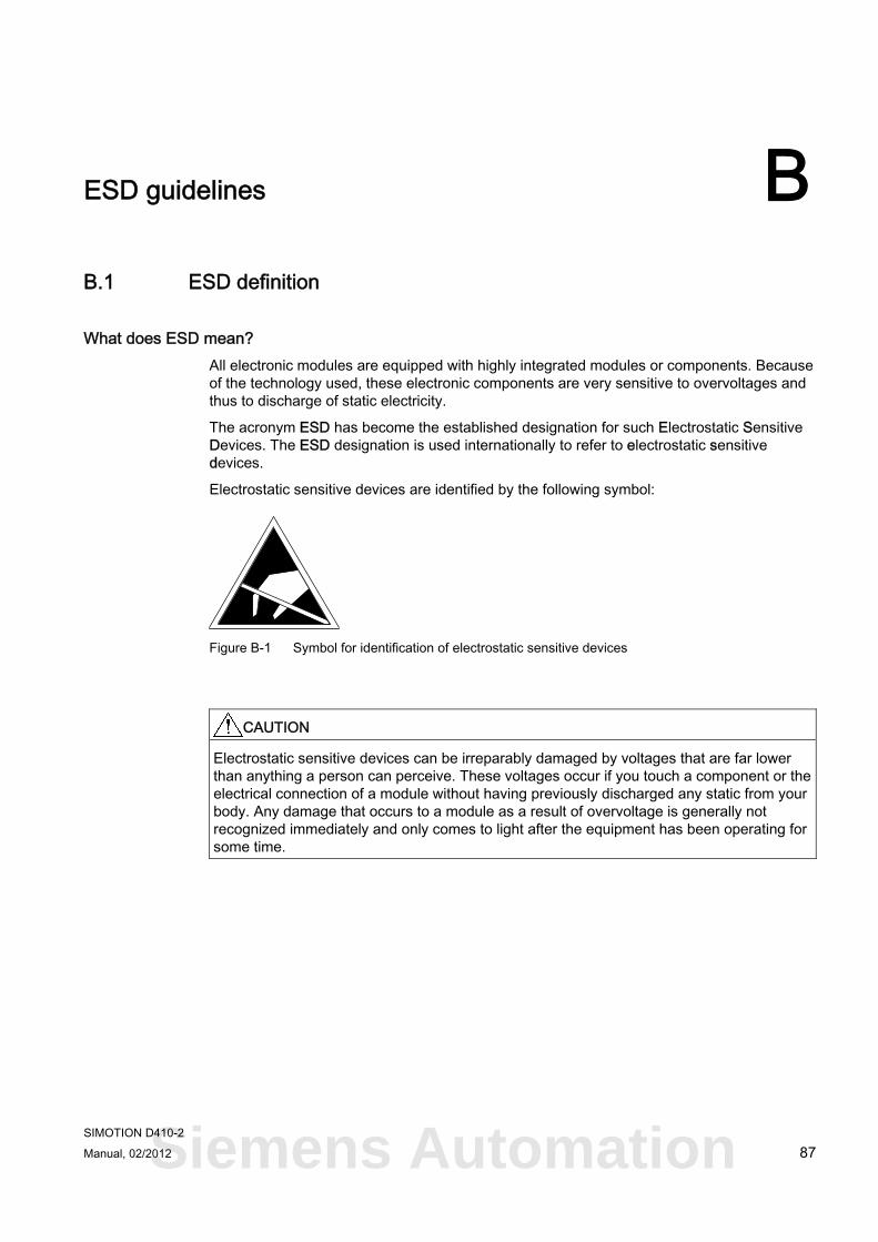
SIMOTION D410-2 Manual, 02/2012 87
ESD guidelines BB.1 ESD definition
What does ESD mean? All electronic modules are equipped with highly integrated modules or components. Because of the technology used, these electronic components are very sensitive to overvoltages and thus to discharge of static electricity.
The acronym ESD has become the established designation for such Electrostatic Sensitive Devices. The ESD designation is used internationally to refer to electrostatic sensitive devices.
Electrostatic sensitive devices are identified by the following symbol:
Figure B-1 Symbol for identification of electrostatic sensitive devices
CAUTION Electrostatic sensitive devices can be irreparably damaged by voltages that are far lower than anything a person can perceive. These voltages occur if you touch a component or the electrical connection of a module without having previously discharged any static from your body. Any damage that occurs to a module as a result of overvoltage is generally not recognized immediately and only comes to light after the equipment has been operating for some time.
Siemens Automation
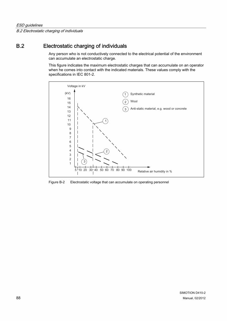
ESD guidelines B.2 Electrostatic charging of individuals
SIMOTION D410-2 88 Manual, 02/2012
B.2 Electrostatic charging of individuals Any person who is not conductively connected to the electrical potential of the environment can accumulate an electrostatic charge.
This figure indicates the maximum electrostatic charges that can accumulate on an operator when he comes into contact with the indicated materials. These values comply with the specifications in IEC 801-2.
Figure B-2 Electrostatic voltage that can accumulate on operating personnel
ESD guidelines B.3 Basic measures for protection against discharge of static electricity
SIMOTION D410-2 Manual, 02/2012 89
B.3 Basic measures for protection against discharge of static electricity
Ensure sufficient grounding When working with electrostatic sensitive devices, make sure that the you, your workstation, and the packaging are properly grounded. This prevents the accumulation of static electricity.
Avoid direct contact You should only touch ESD components if unavoidable (for example, during maintenance work). When you touch modules, make sure that you do not touch either the pins on the modules or the printed conductors. If you follow these instructions, electrostatic discharge cannot reach or damage sensitive components.
If you have to take measurements on a module, make sure that you first discharge any static that may have accumulated in your body. To do this, touch a grounded metal object. Only use grounded measuring instruments.
Siemens Automation

ESD guidelines B.3 Basic measures for protection against discharge of static electricity
SIMOTION D410-2 90 Manual, 02/2012
SIMOTION D410-2 Manual, 02/2012 91
Index
A Accessories, 75
CUA31/CUA32, 81 DMC20 DRIVE-CLiQ hub module, 82 DME20 DRIVE-CLiQ hub module, 82 TM15, 80 TM15 DI/DO, 80 TM17 High Feature, 80 TM31, 77 TM41, 78 TM54F, 78
Address space, 64 Ambient conditions
Climatic, 60 Mechanical, 60
Analog input, 41
B Backup
Non-volatile data, 62
C CAD data, 73 CE marking, 83 Circuit-diagram macro, 73 Clock, 68 CompactFlash card, 21
Data matrix code, 22 Licenses, 21 Properties, 20 Slot, 31 Technical data, 63 Type plate, 21
Component on DRIVE-CLiQ, 16
Conditions of use, 60 Connection examples
with Safety Integrated extended functions, 52 Without safety function, 49
cULus Approval, 83
D Declaration of conformity, 84 DIAG button, 29 Diagnostic buffer, 62 Digital I/Os, 41
Bidirectional, 48 Connection examples, 49 Fail-safe, 47 Technical data, 65
Dimension drawing, 73 Mounting plate, 72 SIMOTION D410-2 DP, 71
Dimensions, 62 Display elements, 25 DMC20
Properties, 82 DMC20 (hub)
Properties, 82 DME20
Properties, 82 DME20 hub
Properties, 82 DRIVE-CLiQ
Connectable devices, 35 Interface, 34 Interface assignment, 34 Interface characteristics, 34
E Electrical connection values, 62 Electromagnetic compatibility, 83 EMC directives, 83 Encoder interface, 38
Interface assignment, 39 Interface characteristics, 38
ESD guideline, 87 Ethernet
Connectable devices, 55 Interface, 55
G Guideline
ESD, 87
Siemens Automation
Index
SIMOTION D410-2 92 Manual, 02/2012
I Interface assignment
X120, 42 X121, 44 X130, 45 X131, 46
Interfaces Analog input (X131), 41 Digital I/Os, 41 DRIVE-CLiQ (X100), 34 Encoder interface (X23), 38 Ethernet (X127), 55 Measuring socket, 57 Power Module Interface, 58 Power supply, 54 PROFIBUS DP, 36 SIMOTION D410-2 DP, 33 Temperature sensor connection (X120), 43
L LED displays, 32 Licenses
Runtime, 21 Licensing, 23
M MAC address, 20 Measuring socket, 57 Memory
SIMOTION D410-2, 62 Mode selector switch, 27 Mounting plate
Data, 63
O Operator controls, 25
DIAG button, 29 Mode selector switch, 27 RESET button, 30 Service selector switch, 26 Switch S5.0, 30
P Performance
Motion Control, 63 PLC, 63
PLC and motion control SIMOTION D410-2 DP performance, 63
PROFIBUS DP interface Assignment, 37
R Real-time clock, 68 References, 4 Reliability
Risk, 85 RESET button, 30 Residual risk, 86 Runtime licenses, 21
S Safety information, 24 Safety of electronic controllers, 85 Service selector switch, 26 Shipping conditions, 59 SIMOTION D410-2
Hardware components, 12 Possible applications, 12 Software components, 13
SIMOTION D410-2 DP Interfaces, 33
Spare parts, 75 Storage conditions, 59
T Technical data
Address space, 64 Analog input, 67 Clock, 68 Communication, 64 CompactFlash card, 63 Digital I/Os, 65 Encoder interface, 67 Mounting plate, 63 SIMOTION D410-2 memory, 62
Temperature sensor connection, 43 Terminal module
TM15, 80 TM15 DI/DO, 80 TM17 High Feature, 80 TM31, 77 TM41, 78 TM54F, 78
Type plate
Index
SIMOTION D410-2 Manual, 02/2012 93
CompactFlash card, 21 SIMOTION D410-2, 19
U UL certification, 83
W Weight, 62
Siemens Automation

Index
SIMOTION D410-2 94 Manual, 02/2012